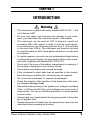
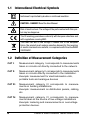
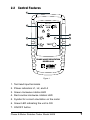
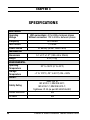
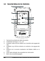
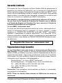
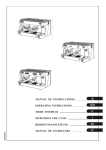
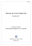
1
PHASE & MOTOR ROTATION METER PROBADOR DE FASE & ROTACIÓN DE MOTOR 6609 600V CAT III 300V CAT IV L1/A L2/B L3/C M R L TEST PHASE & MOTOR ROTATION MODEL 6609 ENGLISH User Manual E S PA Ñ O L Manual de instrucciones Statement of Compliance Chauvin Arnoux®, Inc. d.b.a. AEMC® Instruments certifies that this instrument has been calibrated using standards and instruments traceable to international standards. We guarantee that at the time of shipping your instrument has met its published specifications. The recommended verification interval for this instrument is 12 months and begins on the date of receipt by the customer. For verification, please use our calibration services. Refer to our repair and calibration section at www.aemc.com. Serial #: _ ____________________________ Catalog #: 2121.11 Model #: 6609 Please fill in the appropriate date as indicated: Date Received: _________________________ Date Verification Due: ______________________ Chauvin Arnoux®, Inc. d.b.a AEMC® Instruments www.aemc.com Table of Contents 1. INTRODUCTION...................................................... 3 1.1 International Electrical Symbols......................................4 1.2 Definition of Measurement Categories............................4 1.3 Receiving Your Shipment................................................5 1.4 Ordering Information.......................................................5 1.4.1 Accessories and Replacement Parts..............5 2. PRODUCT FEATURES............................................. 6 2.1 Description......................................................................6 2.2 Control Features.............................................................7 3. SPECIFICATIONS.................................................... 8 4. OPERATION............................................................ 9 4.1 Phase Rotation Direction................................................9 4.2 Indication of Direction of the Rotating Field, or Direction of Rotation without Connecting Test Leads....10 4.3 Determining the Direction of Connection of the Phase Wires to a Motor................................................11 4.4 Solenoid Valve Activation Indication.............................. 11 5. MAINTENANCE..................................................... 12 5.1 Battery Replacement.....................................................12 5.2 Cleaning and Storage...................................................12 Repair and Calibration...................................................................13 Technical and Sales Assistance....................................................13 Limited Warranty...........................................................................14 Warranty Repairs...........................................................................14 CHAPTER 1 INTRODUCTION Warning • This instrument complies with safety standard IEC 61010 - 1, Ed 2 of February 2001. • For your own safety, and to prevent any damage to your instrument, you must follow the instructions given in this manual. • This instrument can be used on CAT III electrical circuits not exceeding 600V with respect to earth. It must be used indoors, in an environment not exceeding pollution level 2, at an altitude of not more than 2000m. The instrument can therefore be used in complete safety on 400V three-phase networks in an industrial environment. • For safety reasons, you must use only measurement leads having a voltage rating and category at least equal to those of the instrument and compliant with standard IEC 61010-031. • Do not use if the cover of the battery compartment is missing or if the housing is damaged or not correctly closed. • Do not place your fingers near unused terminals. • If the instrument is used other than as specified in this manual, the protection provided by the instrument may be impaired. • Do not use this instrument if it seems to be damaged. • Check the integrity of the insulation of the leads and of the housing. Replace damaged leads. • Be prudent when working in the presence of voltages exceeding 70Vdc or 33Vrms and 46.7Vpp; such voltages can cause a risk of electrocution. The use of individual protections is recommended in some cases. • Always keep your hands behind the physical guards of the probe tips or alligator clips. • Always disconnect all leads from the measurement and from the instrument before opening the housing. Phase & Motor Rotation Tester Model 6609 3 1.1 International Electrical Symbols Instrument is protected by double or reinforced insulation. CAUTION - DANGER! Read the User Manual. Risk of electric shock. The voltage at the parts marked with this symbol may be dangerous. The CE marking guarantees conformity with European directives and with regulations covering EMC. The trash can with a line through it means that in the European Union, the product must undergo selective disposal for the recycling of electric and electronic material, in compliance with Directive WEEE 2002/96/EC. 1.2 Definition of Measurement Categories CAT I: Measurement category I corresponds to measurements taken on circuits not directly connected to the network. CAT II: Measurement category II corresponds to measurements taken on circuits directly connected to the installation. Example: measurement for electrodomestic units, portable tools and analogue devices CAT III: CAT IV: 4 Measurement category III corresponds to measurements on building installations. Example: measurement on distribution panels, cabling, etc. Measurement category IV corresponds to measurements taken at the source of low-voltage installations Example: metering and measurements on overvoltage protection devices. Phase & Motor Rotation Tester Model 6609 1.3 Receiving Your Shipment Upon receiving your shipment, make sure that the contents are consistent with the packing list. Notify your distributor of any missing items. If the equipment appears to be damaged, file a claim immediately with the carrier and notify your distributor at once, giving a detailed description of any damage. Save the damaged packing container to substantiate your claim. 1.4 Ordering Information Phase and Motor Rotation Meter Model 6609........Cat. #2121.11 Includes meter, three color-coded test leads (red, black, blue), three alligator clips (black), one 9V battery, soft carrying case and a user manual. 1.4.1 Accessories and Replacement Parts Soft carrying case...................................................... Cat. #2121.54 Set of 3 color-coded leads with black alligator clips CAT III 1000V 10A...................... Cat. #2121.55 Phase & Motor Rotation Tester Model 6609 5 CHAPTER 2 PRODUCT FEATURES 2.1 Description This three-in-one test tool is a must for any plant maintenance staff and will identify proper sequencing for three phase power very quickly and easily. This is also an ideal tool for measuring the proper rotation of motors, conveyors, pumps and other electrical devices interconnected on the power line system before installation. This meter provides the following functions: • Determination of the direction of phase rotation • Presence or absence of phase • Determination of the direction of rotation of a motor with or without connection • Determination of the activation of a solenoid valve without connection 6 Phase & Motor Rotation Tester Model 6609 2.2 Control Features 1 600V CAT III 300V CAT IV 2 L1/A L2/B L3/C M 3 R 4 L 5 6 TEST 7 PHASE & MOTOR ROTATION MODEL 6609 Figure 1 1. Test lead input terminals 2. Phase indicators L1, L2, and L3 3. Green clockwise rotation LED 4. Red counter-clockwise rotation LED 5. Symbol for correct orientation on the motor 6. Green LED indicating the unit is ON 7. ON/OFF button Phase & Motor Rotation Tester Model 6609 7 CHAPTER 3 SPECIFICATIONS ELECTRICAL Operating Voltage With connections: 40 to 600Vac between phases Without connection: 120 to 400Vac between phases Frequency 15 to 400Hz Test Current Power Source MECHANICAL Dimensions Weight ENVIRONMENTAL Operating Temperature Storage Temperature SAFETY Safety Rating < 3.5mA 9V battery (6LR61, NEDA 1604) 5.1 x 2.7 x 1.3" (130 x 69 x 32mm) 6 oz (170g) 32° to 104°F (0° to 40°C) -4° to 122°F (-20° to 50°C); RH < 80% 600V CAT III IEC 61010-1, DIN VDE 0411; IEC 61557-7, DIN VDE 0413-7; Tightness : IP 40 (as per IEC 60529 Ed.92) Double Insulation Yes CE Mark Yes 8 Phase & Motor Rotation Tester Model 6609 CHAPTER 4 OPERATION WARNING: NEVER USE ON ENERGIZED MOTORS! 4.1 Phase Rotation Direction On a three-phase electrical network: 1. Connect the three leads to the instrument, matching the markings. 2. Connect the three alligator clips to the 3 phases of the network to be tested. 3. Press the ON (TEST) button. The Green LED indicates that the instrument is in operation. 4. When the indicators of all three phases are lit, the clockwise (or counter-clockwise) rotation indicator indicates the direction of phase rotation. Warning: The wrong direction of rotation may be displayed if a lead is connected in error to the neutral conductor. Refer to the instrument’s back label for a summary of the various display possibilities. Phase & Motor Rotation Tester Model 6609 9 4.2 Indication of Direction of the Rotating Field, or Direction of Rotation without Connecting Test Leads 1. Do not connect any test leads to the instrument. 2. Position the instrument on the motor, within 2.5 cm, parallel to the shaft in the direction indicated by the symbol on the front panel. 3. Press the ON (TEST) button. The Green LED indicator indicates that the instrument is in operation. 4. The clockwise or counter-clockwise rotation indicator lights to indicate the direction of the rotating field. Note: The instrument does not work on motors controlled by frequency converters. R The table below summarizes the conditions necessary to obtaining a reliable test result. Number of rotations of the Number of rotating field (per minute) as a function of frequency (Hz) pairs of poles 16 2/3 50 60 1 1000 3000 3600 2 500 1500 1800 3 333 1000 1200 4 250 750 900 5 200 600 720 6 167 500 600 8 125 375 450 10 100 300 360 12 83 250 300 16 62 188 225 10 Angle between poles 0 60 30 20 15 12 10 7.5 6 5 3.75 Minimum Ø of the motor casing cm 5.3 10.7 16.0 21.4 26.7 32.1 42.8 53.5 64.2 85.6 Phase & Motor Rotation Tester Model 6609 4.3 Determining the Direction of Connection of the Phase Wires to a Motor .1. Connect the three leads to the instrument, matching the markings. 2. Connect the three alligator clips to the three phase connections on the motor being tested. 3. Press the ON (TEST) button. The Green LED indicator indicates that the instrument is in operation. 4. Turn the motor shaft a half-turn to the right. 5. The clockwise or counter-clockwise rotation indicator lights, indicating whether or not the order of connection of the phase wires is correct. 4.4 Solenoid Valve Activation Indication 1. Do not connect any test leads to the instrument 2. Place the instrument as close as possible to the solenoid valve. 3. Press the ON button. The Green LED indicator indicates that the instrument is in operation. 4. The clockwise or counter-clockwise rotation indicator lights, indicating the presence of the field generated during the activation. Phase & Motor Rotation Tester Model 6609 11 CHAPTER 5 MAINTENANCE 5.1 Battery Replacement WARNING: Always disconnect all leads before replacing a battery or fuse. To replace the battery, proceed as follows: • Remove the screw on the bottom back of the instrument. • Remove the back cover. • Take out the battery and replace with a new 9V battery. (Type NEDA 1604, 6LF22, 6LR61) • Replace the back cover on the case. 5.2 Cleaning and Storage To avoid electrical shock or damage to the meter, do not get water inside the case. • Periodically wipe the case with a damp cloth and mild detergent • Dry completely before using again. • Do not use abrasives or solvents. • If the meter is not to be used for a period of longer then 60 days, remove the battery and store them separately. 12 Phase & Motor Rotation Tester Model 6609 Repair and Calibration To ensure that your instrument meets factory specifications, we recommend that it be submitted to our factory Service Center at one-year intervals for inspection, or as required by other standards or internal procedures. For instrument repair and calibration: You must contact our Service Center for a Customer Service Authorization Number (CSA#). This will ensure that when your instrument arrives, it will be tracked and processed promptly. Please write the CSA# on the outside of the shipping container. Ship To: Chauvin Arnoux®, Inc. d.b.a. AEMC® Instruments 15 Faraday Drive • Dover, NH 03820 USA Tel: (800) 945-2362 or (603) 749-6434 (Ext. 360) Fax: (603) 742-2346 or (603) 749-6309 [email protected] (Or contact your authorized distributor) NOTE: You must obtain a CSA# before returning any instrument. Technical and Sales Assistance If you are experiencing any technical problems, or require any assistance with the proper operation or application of your instrument, please call, mail, fax or e-mail our technical support hotline: Chauvin Arnoux®, Inc. d.b.a. AEMC® Instruments 200 Foxborough Boulevard • Foxborough, MA 02035, USA Phone: (800) 343-1391 or (508) 698-2115 Fax: (508) 698-2118 [email protected] www.aemc.com NOTE: Do not ship Instruments to our Foxborough, MA address. Phase & Motor Rotation Tester Model 6609 13 Limited Warranty The Model 6609 is warranted to the owner for a period of one year from the date of original purchase against defects in manufacture. This limited warranty is given by AEMC® Instruments, not by the distributor from whom it was purchased. This warranty is void if the unit has been tampered with, abused or if the defect is related to service not performed by AEMC® Instruments. For full and detailed warranty coverage, please read the Warranty Coverage Information, which is attached to the Warranty Registration Card (if enclosed) or is available at www.aemc.com. Please keep the Warranty Coverage Information with your records. What AEMC® Instruments will do: If a malfunction occurs within the oneyear period, you may return the instrument to us for repair, provided we have your warranty registration information or a proof of purchase. AEMC® Instruments will, at its option, repair or replace the faulty material. REGISTER ONLINE AT: www.aemc.com Warranty Repairs What you must do to return an Instrument for Warranty Repair: First, request a Customer Service Authorization Number (CSA#) by phone or by fax from our Service Department (see address below), then return the instrument along with the signed CSA Form. Please write the CSA# on the outside of the shipping container. Return the instrument, postage or shipment pre-paid to: Chauvin Arnoux®, Inc. d.b.a. AEMC® Instruments Service Department • 15 Faraday Drive • Dover, NH 03820 USA Tel: (800) 945-2362 or (603) 749-6434 (Ext. 360) Fax: (603) 742-2346 or (603) 749-6309 [email protected] Caution: To protect yourself against in-transit loss, we recommend you insure your returned material. NOTE: You must obtain a CSA# before returning any instrument. 14 Phase & Motor Rotation Tester Model 6609 Tabla de Contenidos 1. INTRODUCCIÓN................................................... 16 1.1 Símbolos Eléctricos Internacionales.............................17 1.2 Definición de las Categorías de Medición.....................17 1.3 Recibiendo su Pedido...................................................18 1.4 Información de Pedidos................................................18 1.4.1 Accesorios y repuestos......................................18 2. CARACTERÍSTICAS DEL PRODUCTO................... 19 2.1 Descripción...................................................................19 2.2 Características de los Controles...................................20 3. ESPECIFICACIONES............................................. 21 4. OPERACIÓN.......................................................... 22 4.1 Sentido de rotación de fases.........................................22 4.2 Indicación del sentido del campo rotativo o sentido de rotación sin conexión........................................23 4.3 Determinación del sentido de conexión de los cables de las fases en un motor.........................................24 4.4 Indicación de la Activación de una válvula de solenoide..................................................................24 5. MANTENIMIENTO................................................. 25 5.1 Cambio de pila..............................................................25 5.2 Limpieza........................................................................25 Reparación y Calibración..............................................................26 Asistencia Técnica y de Ventas.....................................................26 Garantía Limitada..........................................................................27 Reparaciones bajo Garantía.........................................................27 Probador de Fase & Rotación de Motor Modelo 6609 15 CAPÍTULO 1 INTRODUCCIÓN PRECAUCIONES • Este instrumento cumple con la norma de seguridad IEC 61010 – 1 Ed 2 de febrero de 2001. • Para su propia seguridad y para prevenir cualquier daño en este instrumento, debe seguir las instrucciones indicadas en este manual. • Este instrumento se puede utilizar en circuitos eléctricos de categoría III que no supere los 600V respecto de la tierra. El instrumento debe utilizarse en interiores, en un entorno con un grado de contaminación inferior a 2 y a una altitud inferior a 2.000m. El instrumento se puede utilizar con toda seguridad en redes trifásicas de 400V en aplicaciones industriales. • Por razones de seguridad, debe utilizar únicamente cables de medida, de tensión y categoría al menos iguales a los del instrumento y que cumplan con la norma IEC 61010-031. • No utilice el instrumento si la carcasa está dañada o mal cerrada. • No ponga los dedos a proximidad de los terminales que no se utilizan. • Si el instrumento se utiliza de una forma no especificada en el presente manual, la protección proporcionada por el instrumento puede verse alterada. • No utilice este aparato si parece estar dañado. • Controle que el aislamiento de los cables y la carcasa estén en perfecto estado. Cambie los cables que estén dañados. • Tenga cuidado cuando trabaje con tensiones superiores a 70Vdc o 33Vrms y 46,7Vpp, estas tensiones pueden producir electrocución. Dependiendo de las condiciones, se recomienda el uso de protecciones individuales. • Mantenga siempre sus manos detrás de las protecciones de las puntas de prueba o los clipes de cocodrilo • Desconecte siempre las puntas de prueba de los puntos de medida y del instrumento antes de abrir la carcasa. 16 Probador de Fase & Rotación de Motor Modelo 6609 1.1 Símbolos Eléctricos Internacionales Instrumento protegido por un doble aislamiento. Atención, riesgo de peligro. Remítase al manual de instrucciones. ¡Peligro! Riesgo de shock eléctrico. La tensión en la parte marcada con este símbolo puede ser peligroso La marca CE garantiza la conformidad con las directivas europeas así como con la normativa en materia de CEM. Separación de los residuos para el reciclado de los aparatos eléctricos y electrónicos dentro de la Unión Europea. De conformidad con la directiva WEEE 2002/96/EC: este aparato no se debe tratar como un residuo doméstico. 1.2 Definición de las Categorías de Medición CAT I : Medición de la categoría I corresponde a las mediciones adoptadas en relación con los circuitos que no estén directamente conectados. Ejemplo: circuitos electrónicos protegidos. CAT II : Medición de la categoría II corresponde a las mediciones adoptadas en relación con los circuitos conectados directamente a la instalación. Ejemplo: alimentación de aparatos electrodomésticos y de herramientas portátiles. CAT III : Medición de la categoría III corresponde a las mediciones en las instalaciones en edificios. Ejemplo: cuadro de distribución, disyuntores, máquinas o aparatos industriales fijos. CAT IV : Medición de la categoría IV corresponde a las mediciones adoptadas en instalaciones de baja tensión. Ejemplo: entradas de energía, contadores y dispositivos de protección. Probador de Fase & Rotación de Motor Modelo 6609 17 1.3 Recibiendo su Pedido Al recibir su pedido, asegúrese que el contenido corresponde a la lista del pedido solicitado. Avise a su distribuidor en el caso que falte cualquier articulo. Si el equipo llega dañado, presente inmediatamente un reclamo a la empresa de transporte y avise inmediatamente a su distribuidor dando una descripción detallada de cualquier daño. 1.4 Información de Pedidos Indicador de fases y de rotación modelo 6609........Cat. N° 2121.11 Incluye medidor con tres cables de prueba (rojo, negro y azul), tres clips tipo cocodrilo, una batería de 9V, un maletín de transporte blando y manual del usuario. 1.4.1 Accesorios y repuestos Maletín de transporte blando.................................. Cat. N° 2121.54 Conjunto de 3 cables con código de color con clips tipo cocodrilo negros CAT III 1000V 10A........ Cat. N° 2121.55 18 Probador de Fase & Rotación de Motor Modelo 6609 CAPÍTULO 2 CARACTERÍSTICAS DEL PRODUCTO 2.1 Descripción El Modelo 6609 es un instrumento destinado a facilitar la realización de redes de alimentación eléctrica trifásica y reúne en un único instrumento las funciones siguientes: • Determinación del sentido de rotación de fases • Presencia o ausencia de fase • Determinación del sentido de rotación de un motor con o sin conexión ; • Determinación de la activación de la válvula de solenoide sin conexión. Probador de Fase & Rotación de Motor Modelo 6609 19 2.2 Características de los Controles 1 600V CAT III 300V CAT IV 2 L1/A L2/B L3/C M 3 R 4 L 5 6 TEST 7 PHASE & MOTOR ROTATION MODEL 6609 1. Terminal de entrada del cable de prueba 2. Indicadores de fase L1, L2, y L3 3. Indicador verde LCD de rotación en el sentido a las agujas del reloj 4. Indicador rojo LCD de rotación en contrario a las agujas del reloj 5. Símbolo de la correcta orientación del Modelo 6609 en el motor 6. LCD verde indicador de encendido del instrumento 7. Botón de encendido/apagado 20 Probador de Fase & Rotación de Motor Modelo 6609 CAPÍTULO 3 ESPECIFICACIONES ELECTRICAS VOLTAJE Frecuencia Corriente de Prueba Con conexiones: 40 hasta 600VCA entre fases Sin conexiones: 120 hasta 400VCA entre fases 15 hasta 400Hz < 3.5mA Alimentación MECANICAS Batería 9V (6LR61, NEDA 1604) Dimensiones 5.1 x 2.7 x 1.3" (130 x 69 x 32mm) Peso MEDIO AMBIENTE Temperatura de Funcionamiento Temperatura de Almacenamiento SEGURIDAD Calificación de Seguridad 6 oz (170g) 32° hasta 104°F (0° hasta 40°C) -4° hasta 122°F (-20° hasta 50°C); RH < 80% 600V CAT III IEC 61010-1, DIN VDE 0411; IEC 61557-7, DIN VDE 0413-7; Hermeticidad : IP 40 (según IEC 60529 Ed.92) Doble Aislamiento Si Marca CE Si Probador de Fase & Rotación de Motor Modelo 6609 21 CAPÍTULO 4 OPERACIÓN ADVERTENCIA: NUNCA LO UTILICE EN MOTORES CON ENERGIA! 4.1 Sentido de rotación de fases En una red eléctrica trifásica: 1. Conecte los 3 cables al instrumento de forma que correspondan a las marcas. 2. Conecte las 3 pinzas cocodrilo a las 3 fases de la red a probar. 3. Pulse el botón TEST. El indicador luminoso verde indica que el instrumento está funcionando. 4. Cuando los 3 indicadores de fases están encendidos, el indicador de de rotación en el sentido horario (o en el sentido contrario) indica el sentido de rotación de fases. Atención: se puede visualizar un sentido de rotación incorrecto si un cable se ha conectado, por error, al neutro de la red. Consulte la etiqueta del instrumento para obtener un resumen de los diversos posibilidades de visualización. 22 Probador de Fase & Rotación de Motor Modelo 6609 4.2 Indicación del sentido del campo rotativo o sentido de rotación sin conexión 1. Ningún cable debe estar conectado al instrumento; 2. Posicione el instrumento sobre el motor, a menos de 2,5 cm, paralelamente al eje según el sentido del símbolo del frontal. 3. Pulse el botón TEST. El indicador luminoso verde indica que el instrumento está funcionando. 4. El indicador de rotación en el sentido horario o en sentido contrario se enciende para indicar el sentido del campo rotativo. Atención: el instrumento no sirve para motores controlados por convertidores de frecuencia. R La tabla a continuación resume las condiciones requeridas para obtener un resultado de prueba fiable. Número de pares de polos 1 2 3 4 5 6 8 10 12 16 Número de rotaciones del Ángulo entre campo rotativo (1/min) según los polos la frecuencia (Hz) 16 2/3 50 60 0 1000 3000 3600 60 500 1500 1800 30 333 1000 1200 20 250 750 900 15 200 600 720 12 167 500 600 10 125 375 450 7.5 100 300 360 6 83 250 300 5 62 188 225 3.75 Diám. Mínimo de la cubierta del motor Probador de Fase & Rotación de Motor Modelo 6609 cm 5.3 10.7 16.0 21.4 26.7 32.1 42.8 53.5 64.2 85.6 23 4.3 Determinación del sentido de conexión de los cables de las fases en un motor . 1. Conecte los 3 cables al instrumento de forma que correspondan a las marcas; 2. Conecte las 3 pinzas cocodrilo a las 3 conexiones de fase del conector del motor a probar; 3. Pulse el botón TEST. El indicador luminoso verde indica que el instrumento está funcionando; 4. Gire de media vuelta hacia la derecha el eje del motor; 5. El indicador de rotación en el sentido horario o en el sentido contrario se enciende para indicar si se ha respetado o no el orden de conexión de los cables de las fases. 4.4 Indicación de la Activación de una válvula de solenoide 1. Ningún cable debe estar conectado al instrumento. 2. Posicione el instrumento lo más cerca posible de la válvula de solenoide. 3. Pulse el botón TEST. El indicador luminoso verde indica que el instrumento está funcionando. 4. El indicador de rotación en el sentido horario o en el sentido contrario se enciende para indicar la presencia del campo generado durante la activación. 24 Probador de Fase & Rotación de Motor Modelo 6609 CAPÍTULO 5 MANTENIMIENTO 5.1 Cambio de pila Para cambiar la pila, efectúe lo siguiente : 1. Desconecte los cables de la fuente de medida y a nivel del instrumento; 2. Afloje el tornillo en la parte posterior abajo del instrumento; 3. Quite la tapa del alojamiento de la pila; 4. Cambie la pila de 9V (tipo NEDA 1604, 6LF22, 6LR61) y vuelva a fijar la tapa mediante el tornillo. ADVERTENCIA: Desconecte siempre todas las pinzas de prueba antes de reemplazar la batería o el fusible. 5.2 Limpieza 1. Periódicamente limpie la carcasa con un trapo mojado con detergente. 2. Séquelo completamente antes de utilizarlo 3. No utilice productos abrasivos 4. Si el instrumento no es utilizado por un periodo superior a 60 días, desconecte la batería. ADVERTENCIA: Para evitar cortocircuitos o dañar el instrumento, no introduzca agua dentro de la carcasa. Probador de Fase & Rotación de Motor Modelo 6609 25 Reparación y Calibración Para asegurar que su instrumento cumple con las especificaciones de fábrica, recomendamos que lo envíe a nuestro Centro de Servicio para inspección, anualmente o según lo requieran otros estándares o procedimientos internos. Para reparación y calibración del instrumento: Debe contactar nuestro Centro de Servicio para solicitar un Número de Autorización de Servicio al Cliente (CSA#). Esto asegurará que cuando llegue, el instrumento será ingresado y procesado con prontitud. Por favor escriba el CSA# en el exterior del envase. Chauvin Arnoux®, Inc. d.b.a. AEMC® Instruments 15 Faraday Drive, Dover, NH 03820 USA Tel: (800) 945-2362 (Ext. 360) (603) 749-6434 (Ext. 360) Fax: (603) 742-2346 or (603) 749-6309 [email protected] NOTA: Todos los clientes deben obtener un a CSA# antes de enviar cualquier instrumento. Asistencia Técnica y de Ventas Si tiene cualquier problema técnico o necesita ayuda para la correcta operación o aplicación de su instrumento por favor llame, escriba, envíe un fax o e-mail a nuestro soporte técnico: Chauvin Arnoux®, Inc. d.b.a. AEMC® Instruments 200 Foxborough Boulevard • Foxborough, MA 02035, USA Phone: (800) 343-1391 or (508) 698-2115 Fax: (508) 698-2118 [email protected] www.aemc.com NOTA: No envíe instrumentos a nuestra dirección en Foxborough, MA. 26 Probador de Fase & Rotación de Motor Modelo 6609 Garantía Limitada El Probador de Fase & Rotación de Motor Modelo 6609 es garantizados al propietario por defectos de fabricación, por un período de un año desde la fecha original de compra. Esta garantía limitada es dada por AEMC® Instruments, no por el distribuidor a quien se compró el instrumento. Esta garantía queda viciada si la unidad ha sido intervenida, abusada o si la falla se relaciona con un servicio no realizado por AEMC® Instruments. Para detalles y una descripción completa de la cobertura de la garantía, por favor lea la Tarjeta de Cobertura de Garantía, que se adjunta a la Tarjeta de Registro de Garantía. Por favor conserve la Tarjeta de Cobertura de Garantía con sus registros. Lo que AEMC® Instruments hará: Si ocurre una falla de funcionamiento dentro de un año, usted puede devolvernos el instrumento para su reparación sin cargo, siempre y cuando tengamos su TARJETA DE REGISTRO archivada. AEMC® Instruments reparará o reemplazará el material defectuosos, a su discreción. Si no tenemos archivada su tarjeta de registro, le pediremos un comprobante de compra fechado, como también su TARJETA DE REGISTRO junto al material defectuoso. Registro En línea en: www.aemc.com Reparaciones bajo Garantía Lo que Usted debe hacer para enviar un Instrumento para Reparación bajo Garantía: Primero, solicite un Número de Autorización de Servicio al Cliente (CSA#) por teléfono o por fax a nuestro Departamento de Servicio (vea la dirección abajo), luego envíe el instrumento junto con el formulario CSA firmado. Por favor escriba el CSA# en el exterior del envase. Envíe el instrumento con el franqueo o flete prepagado a: Chauvin Arnoux®, Inc. d.b.a. AEMC® Instruments Service Department • 15 Faraday Drive • Dover, NH 03820 USA Tel: (800) 945-2362 or (603) 749-6434 (Ext. 360) Fax: (603) 742-2346 or (603) 749-6309 [email protected] Precaución: Para protegerse contra pérdidas en tránsito, le recomendamos asegurar su mercadería. NOTA: Todos los clientes deben obtener un CSA# antes de enviar un instrument Probador de Fase & Rotación de Motor Modelo 6609 27 11/09 99-MAN 100337 v2 Chauvin Arnoux®, Inc. d.b.a. AEMC® Instruments 15 Faraday Drive • Dover, NH 03820 USA www.aemc.com