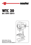
1
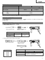
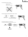
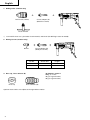
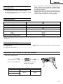
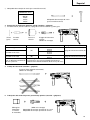
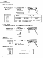
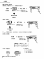
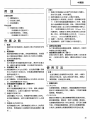
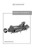
2
1
3
1
4
5
2
3
4
6
7
6
5
8
8
7
3
8
9
1
2
0
4
9
10
B
F
C
E
3
D
4
D
11
12
4
1
G
G
H
3
I
13
14
15
N
J
M
O
L
K
16
J
17
K
2
18
19
P
U
T
a
12 mm
3
Q
V
a
Q
R
5mm
41
S
–
72
W
English
GENERAL OPERATIONAL PRECAUTIONS
1.
2.
3.
4.
5.
6.
7.
8.
9.
10.
11.
12.
13.
14.
15.
16.
17.
18.
19.
5
Keep work area clean. Cluttered areas and benches
invite injuries.
Consider work area environment. Don’t expose
power tools to rain. Don’t use power tools in
damp or wet locations. Keep work area well lit.
Don’t use tool in presence of flammable liquids
or gases.
Power tools produce sparks during operation.
They also spark when switching ON/OFF. Never
use power tools in dangerous sites containing
lacquer, paint, benzine, thinner, gasoline, gases,
adhesive agents, and other materials which are
combustible or explosive.
Guard against electric shock. Prevent body contact
with grounded surfaces. For example; pipes, radiators, ranges, refrigerator enclosures.
Keep children away. Do not let visitors contact
tool or extension cord. All visitors should be kept
away from work area.
Store idle tools. When not in use, tools should
be stored in dry and high or locked-up place—
out of reach of children.
Don’t force tool. It will do the job better and safer
at the rate for which it was intended.
Use right tool. Don’t force small tool or attachment to do the job of a heavy-duty tool. Don’t
use tool for purpose not intended —for example
—don’t use circular saw for cutting tree limbs
or logs.
Dress properly. Do not wear loose clothing or
jewelry. They can be caught in moving parts.
Rubber gloves and non-skid footwear are recommended when working outdoors. Wear protective
hair covering to contain long hair.
Use eye protection. Also use face or dust mask
if cutting operation is dusty.
Don’t abuse cord. Never carry tool by cord or yank
it to disconnect from receptacle. Keep cord from
heat, oil and sharp edges.
Secure work. Use clamps or a vise to hold work.
It’s safer than using your hand and it frees both
hands to operate tool.
Don’t overreach. Keep proper footing and balance
at all times.
Maintain tools with care. Keep tools sharp and
clean for better and safer performance. Follow
instructions for lubricating and changing accessories. Inspect tool cords periodically and if damaged, have repaired by authorized service center.
Inspect extension cords periodically and replace
if damaged. Keep handles dry, clean, and free
from oil and grease.
Disconnect tools. When not in use, before servicing, and when changing accessories, such as
blades, bits, cutters.
Remove adjusting keys and wrenches. Form habit
of checking to see that keys and adjusting wrenches
are removed from tool before turning it on.
Avoid unintentional starting. Don’t carry pluggedin tool with finger on switch. Be sure switch is
off when plugging in.
Outdoor use extension cords. When tool is used
outdoors, use only extension cords intended for
use outdoors and so marked.
Stay alert. Watch what you are doing. Use common sense. Do not operate tool when you are tired.
Check damaged parts. Before further use of the
tool, a guard or other part that is damaged should
be carefully checked to determine that it will
operate properly and perform its intended function. Check for alignment of moving parts, binding
of moving parts, breakage of parts, mounting, and
20.
21.
22.
23.
24.
25.
26.
27.
28.
29.
any other conditions that may affect its operation.
A guard or other part that is damaged should be
properly repaired or replaced by an authorized
service center unless otherwise indicated else
where in this handling instructions. Have defective
switches replaced by authorized service center. Do
not use tool if switch does not turn it on and off.
Use the power tools only for applications specified
in the Handling Instructions.
To avoid personal injury, use only the accessories
or attachment recommended in these handling
instructions or in the HITACHI catalog.
Let only the authorized service center do the
repairing.
The manufacturer will not be responsible for any
damages or injuries caused by repair by unauthorized persons or by mishandling of the tool.
To ensure the designed operational integrity of
power tools, do not remove installed covers or
screws.
Do not touch movable parts or accessories unless
the power source has been disconnected.
Use your tool at lower input than specified on the
nameplate; otherwise, the finish may be spoiled
and working efficiency reduced by motor overload.
Do not wipe plastic parts with solvent. Solvents
such as gasoline, thinner, benzine, carbon tetrachloride, alcohol, ammonia and oil containing
chloric annex may damage and crack plastic parts.
Do not wipe them with such solvent. Wipe plastic
parts with a soft cloth lightly dampened with soapy
water.
Use only genuine HITACHI replacement parts.
Disassemble this tool only for replacement of
carbon brushes.
Use the exploded assembly drawing on this handling instructions only for authorized servicing.
PRECAUTIONS ON USING HAMMER DRILL
1. Wear earplugs to protect your ears during operation.
2. Do not touch the bit during or immediately after
operation. The bit becomes very hot during
operation and could cause serious burns.
3. Before starting to break, chip or drill into a wall,
floor or ceiling, thoroughly confirm that such items
as electric cables or conduits are not buried inside.
4. Always hold the body handle and side handle of
the power tool firmly. Otherwise the counterforce
produced may result in inaccurate and even
dangerous operation.
English
SPECIFICATIONS
Model
DH24PA
Voltage (by areas)*
Power Input
DH24PB
(110V, 115V, 120V, 127V, 220V, 230V, 240V)
620W*
No-load speed
Full-load impact rate
Capacity: concrete
steel
wood
Weight (without cord and side handle)
1050/min.
0 – 1050/min.
4400/min.
3.4 – 24 mm
13 mm
32 mm
2.3 kg
*Be sure to check the nameplate on product as it is subject to change by areas.
STANDARD ACCESSORIES
(1) Case (Molded plastic) ................................................. 1
(2) Side handle ................................................................. 1
(3) Depth gauge ............................................................... 1
Standard accessories are subject to change without
notice.
OPTIONAL ACCESSORIES (sold separately)
1. Drilling anchor holes (rotation + striking)
䡬 Drill bit (Slender shaft)
Drill bit (Slender shaft)
Outer diameter
3.4 mm
3.5 mm
Adapter for slender shaft
(SDS-plus shank)
Drill bit (slender shaft)
Effective length
Overall length
45 mm
90 mm
䡬 Drill bit (Taper shank) and taper shank adapter
Drill bit (Taper shank)
Taper shank adapter
(SDS-plus shank)
Cotter
Outer diameter
11.0 mm
12.3 mm
12.7 mm
14.3 mm
14.5 mm
17.5 mm
21.5 mm
Taper mode
Applicable drill bit
Morse taper (No.1)
Morse taper (No.2)
A-taper
Drill bit (taper shank)
11.0 ~ 17.5 mm
Drill bit (taper shank)
21.5 mm
Taper shank adapter formed A-taper or B-taper
is provided as an optional accessory, but the
drill bit for it is not provided.
B-taper
6
English
䡬 13 mm Hammer drill chuck
For drilling operations when using a straight shank bit for impact drilling with a hammer drill.
shank bit
( Straight
)
for impact drill
13 mm Hammer drill chuck
(SDS-plus shank)
Chuck wrench
2. Anchor setting
䡬 Anchor setting adapter (for electric hammer drill)
Anchor setting adapter (SDS-plus shank)
(for electric hammer drill)
Overall length: 160, 260 mm
Anchor size
W1/4”
W5/16”
W3/8”
䡬 Anchor setting adapter (for manual hammer)
Anchor size
W1/4”
W5/16”
W3/8”
W1/2”
W5/8”
Anchor setting adapter
(for manual Hammer)
3. Large hole boring (rotation + striking)
䡬 Center pin, core bit, core bit shank and guide plate.
(Guide plate) Center pin
Center pin
–
Center pin (A)
Center pin (B)
Do not use core bits with
outer diameter of 25 mm
and 29 mm.
7
Core bit
Core bit shank
(SDS-plus shank)
Core bit (outer diameter)
25 mm
29 mm
(A)
32 mm
35 mm
38 mm
45 mm
(B)
50 mm
with guide plate
(The guide plate is not equipped with core bits
with outer diameter of 25 mm and 29 mm.)
Core bit shank
Core bit shank (A)
Core bit shank (B)
English
4. Crushing operation (rotation + striking)
Bull point (Round type only)
(SDS-plus shank)
5. Bolt placing operation with Chemical Anchor. (rotation + striking)
socket
(Standard
on the market )
(SDS-plus shank)
12.7 mm Chemical Anchor Adapter
19 mm Chemical Anchor Adapter
6. Drilling holes and driving screws (rotation only)
䡬 Drill chuck, chuck adapter (G), special screw and chuck wrench
Special screw
Drill chuck (13 VLR)
Chuck adapter (G)
(SDS-plus shank)
Chuck wrench
8
English
7. Drilling holes (rotation only)
Drill chuck (13VLA)
Chuck adapter (D)
(SDS Plus shank)
Chuck wrench
䡬 13 mm drill chuck ass’y (includes chuck wrench) and chuck (for drilling in steel or wood).
8. Driving Screws (rotation only)
Chuck adapter (D)
(SDS-plus shank)
Bit No.
Bit No.
Screw Size
Length
No. 2
3 – 5 mm
25 mm
No. 3
6 – 8 mm
25 mm
9. Dust cup, Dust collector (B)
Dust cup
10. Hammer grease A
500 g (in a can)
70 g (in a green tube)
30 g (in a green tube)
Dust collector (B)
Optional accessories are subject to change without notice.
9
English
APPLICATIONS
Rotation and striking function
䡬 Drilling anchor holes
䡬 Drilling holes in concrete
䡬 Drilling holes in tile
Rotation only function
䡬 Drilling in steel or wood
(with optional accessories)
䡬 Tightening machine screws, wood screws
(with optional accessories)
PRIOR TO OPERATION
1. Power source
Ensure that the power source to be utilized conforms
to the power requirements specified on the product
nameplate.
2. Power switch
Ensure that the power switch is in the OFF position. If
the plug is connected to a power receptacle while the
power switch is in the ON position, the power tool will
start operating immediately, which could cause a
serious accident.
3. Extension cord
When the work area is removed from the power
source, use an extension cord of sufficient thickness
and rated capacity. The extension cord should be kept
as short as practicable.
4. Mounting the drill bit (Fig. 1)
(1) To attach a drill bit (SDS-plus shank), fully pull the grip
in the direction of the arrow as shown in Fig. 1 and
insert the drill bit as far as it will go while manually
turning.
(2) By releasing the grip, the drill bit will be secured.
(3) To remove the drill bit, fully pull the grip in the
direction of the arrow and pull out the drill bit.
5. Installation of dust cup or dust collector (B)
(Optional accessories) (Fig. 2, Fig. 3)
When using a hammer drill for upward drilling
operations attach a dust cup or dust collector (B) to
collect dust or particles for easy operation.
䡬 Installing the dust cup
Use the dust cup by attaching to the drill bit as shown
in Fig. 2.
When using a bit which has big diameter, enlarge the
center hole of the dust cup with this hammer dirll.
䡬 Installing dust collector (B)
When using dust collector (B), insert dust collector (B)
from the tip of the bit by aligning it to the groove on the
grip. (Fig. 3)
CAUTION:
䡬 The dust cup and dust collector (B) are for exclusive
use of concrete drilling work. Do not use them for
wood or metal drilling work.
䡬 Insert dust collector (B) completely into the chuck part
of the main unit.
䡬 When turning the hammer drill on while dust collector
(B) is detached from a concrete surface, dust collector
(B) will rotate together with the drill bit. Make sure to
turn on the switch after pressing the dust cup on the
concrete surface. (When using dust collector (B)
attached to a drill bit that has more than 190 mm of
overall length, dust collector (B) cannot touch the
concrete surface and will rotate. Therefore please use
䡬
䡬
6.
7.
dust collector (B) by attaching to drill bits which have
166 mm, 160 mm, and 110 mm overall length.
Dump particles after every two or three holes when
drilling.
Please replace the drill bit after removing dust collector
(B).
Selecting the driver bit
Screw heads or bits will be damaged unless a bit
appropriate for the screw diameter is employed to
drive in the screws.
Confirm the direction of bit rotation (Fig. 4)
The bit rotates clociwise (viewed from the rear side) by
pushing the R-side of the reversing switch lever. The
L-side of the lever is pushed to turn the bit
counterclockwise.
HOW TO USE
CAUTION:
To prevent accidents, make sure to turn the switch off and
disconnect the plug from the receptacle when the drill pits
and other various parts are installed or removed. The
power switch should also be turned off during a work
break and after work.
1. Switch operation
(1) DH24PA
By pulling the trigger switch and depressing the
stopper, the switch is held in the ON position for
continuous operation. To turn the drill OFF, pull the
trigger switch again and release.
(2) DH24PB
The rotation speed of the drill bit can be controlled
steplessly by varying the amount that the trigger
switch is pulled. Speed is low when the trigger switch
is pulled slightly and increases as the switch is pulled
more. Continuous operation may be attained by
pulling the trigger switch and depressing the stopper.
To turn the switch OFF, pull the trigger switch again
to disengage the stopper, and release the trigger
switch to its original position.
2. Rotation + striking
This hammer drill can be set to rotation and striking
mode by turning the change lever fully countermark. (Fig. 5)
clockwise to the
(1) Mount the drill bit.
(2) Pull the trigger switch after applying the drill bit tip to
the drilling position. (Fig. 6)
(3) Pushing the hammer drill forcibly is not necessary at
all. Pushing slightly so that drill dust comes out
gradually is sufficient.
CAUTION:
When the drill bit touches construction iron bar, the bit
will stop immediately and the hammer drill will react
to revolve. Therefore grip the side handle and handle
tightly as shown in Fig. 6.
3. Rotation only
The hammer drill can be set to rotation only mode by
rotating the change lever fully clockwise to the
mark. (Fig. 7)
To drill wood or metal material using the drill chuck
and chuck adapter (optional accessories), proceed as
follows.
Installing drill chuck and chuck adapter: (Fig. 8)
10
English
(1) Attach the drill chuck to the chuck adapter.
(2) The part of the SDS-plus shank is the same as the drill
bit. Therefore, refer to the item of “Mounting the drill
bit” for attaching it.
CAUTIONS:
䡬 Application of force more than necessary will not only
expedite the work, but will deteriorate the tip edge of
the drill bit and reduce the service life of the hammer
drill in addition.
䡬 Drill bits may snap off while withdrawing the hammer
drill from the drilled hole. For withdrawing, it is
important to use a pushing motion.
䡬 Do not attempt to drill anchor holes or holes in concrete
with the machine set in the rotation only function.
䡬 Do not attempt to use the hammer drill in the rotation
and striking function with the drill chuck and chuck
adapter attached. This would seriously shorten the
service life of every component of the machine.
4. When driving machine screws (Fig. 9)
First, insert the bit into the socket in the end of chuck
adapter (D).
Next, mount chuck adapter (D) on the main unit using
procedures described in 4 (1), (2), (3), put the tip of the
bit in the slots in the head of the screw, grasp the main
unit and tighten the screw.
CAUTIONS:
䡬 Exercise care not to excessively prolong driving time,
otherwise, the screws may be damaged by excessive
force.
䡬 Apply the hammer drill perpendicularly to the screw
head when driving the screw; otherwise, the screw
head or bit will be damaged, or driving force will not
be fully transferred to the screw.
䡬 Do not attempt to use the hammer drill in the rotation
and striking function with the chuck adapter and bit
attached.
5. When driving wood screws (Fig. 9)
(1) Selecting a suitable driver bit
Employ plus-head screws, if possible, since the driver
bit easily slips off the heads of minus-head screws.
(2) Driving in wood screws
䡬 Prior to driving in wood screws, make pilot holes
suitable for them in the wooden board. Apply the bit
to the screw head grooves and gently drive the screws
into the holes.
䡬 After rotating the hammer drill at low speed for a while
until the wood screw is partly driven into the wood,
squeeze the trigger more strongly to obtain the
optimum driving force.
CAUTION:
Exercise care in preparing a pilot hole suitable for the
wood screw taking the hardness of the wood into
consideration. Should the hole be excessively small
or shallow, requiring much power to drive the screw
into it, the thread of the wood screw may sometimes
be damaged.
6. Using depth gauge (Fig. 10)
(1) Loosen the knob on the side handle, and insert the
depth gauge into the mounting hole on the side
handle.
(2) Adjust the depth gauge position according to the
depth of the hole and thighten the knob securely.
7. How to use the drill bit (taper shank) and the taper
shank adapter
(1) Mount the taper shank adapter to the hammer drill.
(Fig. 11)
11
(2) Mount the drill bit (taper shank) to the taper shank
adapter. (Fig. 11)
(3) Turn the switch ON, and drill a hole in prescribed
depth.
(4) To remove the drill bit (taper shank), insert the cotter
into the slot of the taper shank adapter and strike the
head of the cotter with a hammer supporting on a
rests. (Fig. 12)
HOW TO USE THE CORE BIT
(FOR LIGHT LOAD)
When boring penerating large holes use the core bit (for
light loads). At that time use with the center pin and the
core bit shank provided as optional accessories.
1. Mounting
CAUTION
Be sure to turn power OFF and disconnect the plug
from the receptacle.
(1) Mount the core bit to the core bit shank. (Fig. 13).
Lubricate the thread of the core bit shank to facilitate
disassembly.
(2) Mount the core bit to the hammer drill (Fig. 14).
(3) Insert the center pin into the guide plate until it stops.
(4) Engage the guide plate with the core bit, and turn the
guide plate to the left or the right so that it does not fall
even if it faces downward. (Fig. 15).
2. How to bore (Fig. 16)
(1) Connect the plug to the power source.
(2) A spring is installed in the center pin.
Push it lightly to the wall or the floor straight.
Connect the core bit tip flush to the surface and start
operating.
(3) When boring about 5 mm in depth the position of the
hole will be established. Bore after that removing the
center pin and the guide plate from core bit.
(4) Application of excessive force will not only expedite
the work, but will deteriorate the tip edge of the drill
bit, resulting in reduced service life of the hammer
drill.
CAUTION
When removing the center pin and the guide plate,
turn OFF the switch and disconnect the plug from the
receptacle.
3. Dismounting (Fig. 17)
Remove the core bit shank from the hammer drill and
strike the head of the core bit shank strongly two or
three times with a hammer holding the core bit, then
the thread becomes loose and the core bit can be
removed.
LUBRICATION
Low viscosity grease is applied to this hammer drill so
that it can be used for a long period without replacing the
grease. Please contact the nearest service center for
grease replacement when any grease is leaking form
loosened screw.
Further use of the hammer drill with lock off grease will
cause the machine to seize up reduce the service life.
CAUTION:
A special grease is used with this machine, therefore, the
normal performance of the machine may be badly affected
by use of other grease. Please be sure to let one of our
service agents undertake replacement of the grease.
English
MAINTENANCE AND INSPECTION
1. Inspecting the drill bits
Since use of a dull tool will cause motor
malfunctioning and degraded efficiency, replace the
drill bit with new ones or resharpen them without
delay when abrasion is noted.
2. Inspecting the mounting screws:
Regularly inspect all mounting screws and ensure that
they are properly tightened. Should any of the screws
be loose, retighten them immediately. Failure to do so
could result in serious hazard.
3. Maintenance of the motor
The motor unit winding is the very heart” of the power
tool. Exercise due care to ensure the winding does not
become damaged and/or wet with oil or water.
4. Inspecting the carbon brushes (Fig. 18)
The motor employs carbon brushes which are
consumable parts. When they become worn to or near
“wear limit”, it could result in motor trouble. When an
auto-stop carbon brush is equipped, the motor will
stop automatically.
At that time, replace both carbon brushes with new
ones which have the same carbon brush numbers
shown in Fig. 18.
In addition, always keep carbon brushes clean and
ensure that they slide freely within the brush holders.
5. Replacing a carbon brush (Fig. 19)
䡬 Disassembling
(1) Loosen the three screws on the handle cover, and
remove the handle cover.
(2) Lift out the brush holder together with the carbon
brush, while being very careful not to forcibly pull the
lead wires within the brush holder.
(3) Withdraw the brush terminal, and remove the carbon
brush from the brush holder.
䡬 Reassembling
(1) Place a new carbon brush into the brush holder, and
connect the brush terminal to the carbon brush.
(2) Return the brush holder and other parts to their original
positions, as illustrated in Fig. 19.
(3) Place the lead wire in the specified position. Be very
careful not to allow the lead wire to contact the
armature or rotating parts of the motor.
(4) Replace the handle cover, while being careful to ensure
it does not pinch the lead wire, and secure it firmly
with the three screws.
CAUTION
Should the lead wire be pinched by the handle cover
or come in contact with the armature or rotating parts
of the motor, a serious danger of electric shock to the
operator will be created. Excercise extreme caution in
disassembling and reassembling the motor, following
the above procedures exactly.
Do not attempt to disassemble any parts other than
those necessary to effect replacement of the carbon
brush.
NOTE:
Due to HITACHI’s continuing program of research and
development, the specifications herein are subject to
change without prior notice.
12
Españal
PRECAUCION GENERAL POR OPERACION
1.
2.
3.
4.
5.
6.
7.
8.
9.
10.
11.
12.
13.
13
Mantener el área de trabajo limpia, áreas y
bancos de trabajo desordenados son causa de
da ños personales.
Considerar el medio ambiente del área de trabajo.
No exponer las herramientas eléctricas a la lluvia.
No usar herramientas eléctricas en lugares moja
dos o húmedos. Mantener el área de trabajo
bien iluminada.
No usar las herramientas eléctricas en lugares
donde existan líquidos inflamables o gases.
Las herramientas eléctricas producen chispas
durante la operación y también durante el encendido y el apagado. No utilizar nunca herramientas
eléctricas en lugares peligrosos que contengan
laca, pintura, bencina, disolventes, gasolina,
gases, agentes adhesivos y otros materiales que
sean combustibles o que pudiesen explotar.
Protegerse contra descargas eléctricas. Evitar el
contacto del cuerpo con las superficies puestas
a tierra. Por ejemplo; tubos, radiadores, cocinas
eléctricas, refrigeradores.
Mantener a los ni ños alejados. No dejar que los
visitantes toquen las herramientas ni los cables
de extensión. Todos los visitantes deberán mantenerse alejados del área de trabajo.
Guardar las herramientas que no se usen y
ponerlos en lugares secos, altos o cerrados,
fuera del alcance de los ni ños.
No forzar las herramientas, éstas trabajarán más
y con mayor seguridad cuando cumplan con las
especificaciones para las cuales fueron
dise ñadas.
Usar las herramientas apropiadas. No forzar pequeñas herramientas o accesorios a realizar el trabajo
de herramientas de mayor potencia. No utilizar
herramientas para otros propósitos para los cuales
no fueron dise ñadas, por ejemplo, no utilizar
sierras circulares para cortar ramas de árboles o
troncos.
Vestir apropiadamente. No ponerse ropas que queden flojas ni tampoco joyas. Estas podrían quedar
atrapadas en las partes móviles de las herramientas.
Cuando se trabaje en exteriores, se recomienda
el uso de guantes de goma y calzado que no resbale.
Usar gafas de protección. Usar también
mascarillas contra el polvo si las condiciones de
corte fuesen polvorientas.
Cuidar del cable. Nunca lleve las herramientas
colgando del cable, tampoco tire del cable para
efectuar la desconexión de las herramientas.
Mantener el cable alejado del calor, aceite y
bordes agudos.
Asegurar la pieza de trabajo usando para ello
abrazaderas o un tornillo. Esto es más seguro
que usar las manos, ademas, ambas manos
quedan libres para operar la herramienta.
No extenderse excesivamente para efectuar un
trabajo. Mantener en todo momento un buen
balance y base de apoyo.
Mantener cuidadosamente las herramientas. Tener
las siempre limpias y afiladas para obtener un
mejor rendimiento y un funcionamiento más
seguro.
Seguir siempre las instrucciones para la lubricación
y el cambio de accesorios. Inspeccionar periódicamente los cables de las herramientas y si estuviesen da ñados, hacer que los reparen técnicos
ó expertos. Inspeccionar periodicamente los cables de extensión y cambiarlos si estuviesen
da ñados. Mantener los mangos secos, limpios, y
libres de aceite y grasa.
14.
15.
16.
17.
18.
19.
20.
21.
22.
23.
24.
25.
26.
27.
28.
29.
Desconectar las herramientas cuando no se usen,
antes de repararlas, y cuando se cambien accesorios como por ejemplo, cuchillas, brocas,
cortadores, etc.
Quitar las cuñas y las llaves de tuercas. Acostumbrarse a comprobar si se han quitado las cu ñas
y las llaves de tuercas antes de poner las
herramientas en funcionamiento.
Evitar puestas en funcionamiento sin fin alguno.
No llevar las herramientas con los dedos en los
interruptores mientras que éstas cstán conectadas.
Cuando se conecten las herramientas, cerciorarse
de que los interruptores esten en la posición de
desconectados.
Para usos en exteriores usar cables de extensión.
Cuando las herramientas vayan a ser usadas en
exteriores, usar solamente cables de extensión
diseñados para tal propósito.
Estar siempre alerta y poner atención a lo que se
está haciendo, usar el sentido común y no operar
con la herramienta cuando se esté cansado.
Comprobar las piezas dañadas. Antes de seguir
con el funcionamiento de las herramientas, las
piezas que estén dañadas deberán comprobarse
cuidadosamente para determinar si pueden funcionar apropiadamente y cumplir con la función
para las que fueron dise ñadas. Comprobar el
alineamiento y agarrotamiento de piezas móviles,
rotura de piezas, montura, y cualquier otra anomalia
que pudiese afectar al rendimiento de la
herramienta. Cualquier pieza que estuviese da ñada
deberá repararse apropiadamente o cambiarse en
un centro de reparaciones autorizado, al menos
que se indique, lo contrario en este manual de
instrucciones. Procurar que los interruptores
defectuosos los cambie un centro de reparaciones
autorizado.
No usar las herramientas si sus interruptores no
funcionasen apropiadamente.
No usar herramientas eléctricas para otras aplicaciones que no sean las especificadas en las
Instrucciones de Manejo.
El uso de cualquier recambio o accesorio que no
venga recomendado en el manual de instrucciones
o catálogo HITACHI puede ocasionar el da ño de
la máquina.
La reparación de cualquier máquina debe ser
efectuada por un servicio autorizado.
El fabricante no es responsable de ningun daño
causado por la reparación que una persona no
autorizada hubiese realizado, ni tampoco del
maltrato de la máquina.
Para asegurar la integridad operacional de las
herramientas eléctricas, no quitar las cubiertas ni
los tornillos instalados.
No tocar piezas móviles ni accesorios a menos que
la alimentación haya sido desconectada.
Utilizar las herramientas eléctricas con una corriente de entrada inferior a la especificada en la
placa de identificación, de otra forma, el acabado
se estropearia y la eficiencia de trabajo se reduciría
debido a la sobrecarga del motor.
No limpiar las partes de plásticos con disolventes,
como gasolina, diluyente de bencina, tetracloruro
de carbono, alcohol, amoníaco y aceite porque
contienen aditamentos clóricos que pueden agrietar las partes del plastico.
No limpiarlas con tales disolventes.
Limpiar las partes de plástico con un pa ño suave
ligeramente humedecido en agua jabonosa.
Usar solamente piezas de repuesto HITACHI.
Esta herramienta deberá desmontarse solamente
para cambiar las escobillas de carbón.
El despiece presentado en el manual de instrucciones solo debe ser utilizado por un servicio
autorizado.
Español
PRECAUCIONES AL USAR EL MARTILLO
ROTO-PERCUTOR
1. Usar protectores de oídos durante el trabajo.
2. No tocar la broca durante ni inmediatamente después
de trabajar, puesto que se pone ardiente y puede
causar quemaduras serias.
3. Antes de empezar a romper, picar o perforar en una
pared, suelo o techo, comprobar cuidadosamente
que no hayan objetos empotrados, tales como cables
o conductos eléctricos.
4. Sujetar siempre firmemente el asidero del cuerpo y el
asidero lateral de la herramienta. De lo contrario, la
contrafuerza producida podría causar un
funcionamiento impreciso e incluso peligroso.
ESPECIFICACIONES
Model
DH24PA
Voltaje (por áreas)*
DH24PB
(110V, 115V, 120V, 127V, 220V, 230V, 240V)
Acometida
620W*
Velocidad sin carga
1050/min.
Velocidad de percusión a carga plena
0 – 1050/min.
4400/min
Capacidad: hormigón
acero
madera
3,4 – 24 mm
13 mm
32 mm
Peso (sin cable ni mango lateral)
2,3 kg
* Verificar indefectiblemente los datos de la placa de características de la máquina, pues varían de acuerdo con el país
de destino.
ACCESORIOS ESTANDAR
(1) Caja (Plástica) ............................................................. 1
(2) Mango lateral .............................................................. 1
(3) Calibre de profundidad .............................................. 1
Los accesorios estándar están sujetos a cambio sin previo
aviso.
ACCESORIOS FACULTATIVOS (de venta por separado)
1. Taladrar orificios de anclaje (rotación + golpeteo)
䡬 Broca de taladro (Eje fino)
Broca de taladro (Eje fino)
Adaptador para eje fino
(SDS más vástago)
Broca de taladro (Eje fino)
Diámetro externo
3,4 mm
Longitud efectiva
Longitud total
45 mm
90 mm
3,5 mm
14
Españal
䡬 Broca de taladro (vástago cónico) y adaptador cónico
Broca de taladro (Vástago cónico)
Adaptador cónico
(SDS más vástago)
Chaveta
Diámetro externo
11,0 mm
12,3 mm
12,7 mm
14,3 mm
14,5 mm
17,5 mm
21,5 mm
Modo cónico
Broca de taladro aplicable
Cono Morse (No.1)
Broca de taradro
(vástago cónico)
Cono Morse (No.2)
Broca de taradro
(vástago cónico)
Cono A
Cono B
11,0 ~ 17,5 mm
21,5 mm
El cono A o B troquelado del adaptador cónico as
suministra como accesorio facultativo pero la
broca para el mismo no se suministra.
䡬 Portabrocas del martillo roto-percutor de 13 mm
Para la operación de taladrado cuando emplee una broca de vástago recto para taladrar con un martillo rotopercutor.
Broca de vástago recto
( para martillo roto-percutor )
Portabrocas del martillo
roto-percutor de 13 mm
(SDS más vástago)
Llave de portabrocas
2. Montaje de ancla
䡬 Adaptador de montaje de ancla (para martillo roto-percutor)
Adaptador de montaje de ancla (SDS más vástago)
(para martillo roto-percutor)
Longitud total: 160 mm 260 mm
Medida de ancla
W1/4”
W5/16”
W3/8”
15
Español
䡬 Adaptador de montaje de ancla (para martillo manual)
Medida de ancla
W1/4”
W5/16”
W3/8”
W1/2”
W5/8”
Adaptador de montaje de ancla
(para martillo manual)
3. Pertoración de orificio de diámetro grande (rotation + golpeteo)
䡬 Pasador central, barrena tubular, espiga de la barrena tubular y placa guía.
(Placa
guia)
Pasador
central
Barrena
tubular
Espiga de la barrena
tubular
(SDS más vástago)
Pasador central
Barrent tubular (diámetro externo)
Espiga de la barrena tubular
25
mm
–
29 mm
(A)
32 mm
Espiga de la barrena tubular (A)
Pasador central (A)
35 mm
38 mm
45 mm
Pasador central (B)
(B)
Espiga de la barrena tubular (B)
50 mm
No usar barrenas tubulares Con placa guía
con un diámetro externo de (La placa guía no se ha equipado con barrenas
25 mm y 29 mm.
tubulares con diámetro externo de 25 mm y 29 mm.)
4. Travajo de roturación (rotation + golpeteo)
Puntero (Tipo redondo solamente)
(SDS más vástago)
5. Trabajo de colocación de pernos para anclaje químico (rotación + golpeteo)
(Manguito
adaptador
a la venta
el mercado)
(SDS más vástago)
Adaptador de anclaje químico de 12,7 mm
Adaptador de anclaje químico de 19 mm
16
Españal
6. Perforación (rotación solamente)
䡬 Portabrocas, adaptador (G) del portabrocas, tornillo especál y llave de portabrocas
Tornillo especial
Porabrocas
(13 VLR)
Adaptador (G) de portabrocas
(SDS más vástago)
Llave de portabrocas
7. Perforación (rotación solamente)
Portabrocas (13 VLA)
Adaptador (D) del portabrocas
(SDS más vástago)
Liave de portabrocas
䡬 Conjunto de portabrocas 13 mm (con llave de portabrocas) y portabrocas (para perforación de orificios en
hormigón o madera.)
8. Colocación de tornillos (rotación solamente)
No. de broca
Adaptador (D) del portabrocas
(SDS más vástago)
No. de broca
Tamaño del tornillo
Longitud
No.2
3 – 5 mm
25 mm
No.3
6 – 8 mm
25 mm
9. Copa de polvo, Colector de polvo (B)
Copa de polvo
10. Grasa A para martillo
500 g (en una lata)
70 g (en un tubo naranja)
30 g (en un tubo naranja)
Colector de polvo (B)
Los accesorios de norma están sujetos a cambio sin previo aviso.
17
Español
APPLICACION
Acción combinada de rotación y golpeteo
䡬 Perforación de orificios de anclaje
䡬 Perforación de orificios de hormigón
䡬 Perforación de orificios de baldosa
Rotación solamente
䡬 Perforación de orificios en hormigón o madera (con
accesorios facultativos)
䡬 Apretar tornillos en metal o madera.
(con accesorios facultativos)
ANTES DE LA PUESTA EN MARCHA
1. Alimentación
Asegurarse de que la alimentación de red que ha de
ser utilizada responda a las exigencias de corriente
especificadas en la placa de características del
producto.
2. Conmutador de alimentación
Asegurarse de que el conmutador de alimentación
esté en la posición OFF (desconectado). Si la clavija
está conectada en la caja del enchufe mientras el
conmutador de alimentación esté en posición ON
(conectado) las herramientas eléctricas empezarán a
trabajar inmediatamente, provocando un serio
accidente.
3. Cable de prolongación
Cuando está alejada el área de trabajo de la red de
alimentación, usar un cable de prolongación de un
grosor y potencia nominal suficiente. El cable de
prolongación debe ser mantenido lo más corto posible.
4. Montaje de la broca (Fig. 1)
(1) Para colocar una broca (SDS más vástago), tire
completamente de la empuñadura en el sentido de la
flecha como se muestra en la Fig. 1 en inserte
profundamente la froca girándola.
(2) Al soltar la empuñadura, la broca quadará asegurada.
(3) Para extraer la broca, tire completamente de la
empuñadura en el sentido de la flecha y tire hacia
afuera de la broca.
5. Cuando instale la copa de polvo o el lector de polvo (B)
(Accesorios facultativos)(Fig. 2, Fig. 3)
Cuando emplee un martillo roto-percutor para trabajos
de taladrado hacia arriba, extraiga el adaptador de
recolección de polvo e instale una copa de polvo o un
colector de polvo (B) para recolectar las partículas a fin
de facilitar la operación.
䡬 Instalación de la copa de polvo
Emplee la copa de polvo instalando la broca como se
muestra en la Fig. 2.
Cuando emplee una broca de gran diámetro, agrande
el orificio central de la copa de polvo con este martillo
roto-percutor.
䡬 Instalacion del colector de polvo (B)
Para emplear el colector de polvo (B), Insértelo desde
la punta de la broca alineándolo con la ranura de la
empuñadura. (Fig. 3)
PRECAUCION:
䡬 La copa de polvo y el colector de polvo (B) son para
emplearse exclusvamente en trabajos de perforación
de hormigón. No los emplee para trabajar con madera
o metal.
䡬 Inserte completamente el colector de polvo (B) en la
parte del portabrocas de la unidad principal.
䡬 Cuando ponga en funcionamiento del martillo
rotopercutor meintras el colector de polvo (B) esté
separado de la superficie de hormigón, dicho colector
girará junto con la broca. Cerciórese de apretar el
gatillo interruptor después de haber presionado la
copa de polvo sobre la superficie de hormigón. (Cuando
emplee la copa de polvo con una broca de no más de
190 mm de longitud total, el colector de polvo (B) no
podrá tocar la superficie de hormigón girará.
Por lo tanto, emplee el colector de polvo (B) con
brocas de 166, 160, y 110 mm de longitud total.)
䡬 Vacíe las partículas del colector de polvo (B) después
de haber taladrado dos o tres orificios.
䡬 Después de haber extraído el colector de polvo (B),
vuelva a colocar a broca.
6. Selección de la broca destornillador
Puede dañarse las cabezas de tornillos y las brocas de
atornillar menos que se emplee la broca apropiada
según sea el diámetro del tornillo.
7. Confirmar la dirección de rotación de la broca (Fig. 4)
La broca rota hacia la derecha (mirándola desde atrás)
al oprimir el lado R (der.) de la palanca interruptora de
inversión.
El lado L (izp.) de la palanca se us para hacer girar la
broca a la izquierda.
COMO SE USA
PRECAUCION:
Para evitar accidentes, cerciórese de poner este
interruptor en OFF y de desconectar el enchufe del
tomacorriente cuando instale o extraiga brocas y
otras piezas. El interruptor de alimentación también
deberá ponerse en OFF durante un descanso en el
trabajo y después de haber finalizado dichotrabajo.
1. Operación del conmutador
(1) DH24PA
Apretando el pulsador y apretando hacia abajo el
dispositivo de ajuste, el pulsador se mantiene en
posición ON (conectado) para la operación continua.
Para desconectar en OFF el taladrador, volver a apretar
el pulsador y soltarlo.
(2) DH24PB
La velocidad rotatoria de la broca de taladro puede ser
controlad variando la fuerza con la que se aprieta el
pulsador. La velocidad está baja cuando se aprieta
ligeramente el pulsador y se aumenta al apretar más
el pulsador. La operación contínua puede ser alcanzada
apretando el pulsador y apretando hacia abajo el
dispositivo de ajuste. Para ponel el pulsador en OFF
(desconectado) volver a apretar el pulsador para
desconectar el dispositivo de ajuste, y soltar el pulsador
a su posición normal.
2. Rotación + golpeteo
Este martillo roto-percutor puede usarse en el modo
de rotación y golpeteo girando la palanca selectora
completamente hacia la izquierda, hacia la marca .
(Fig. 5)
(1) Montar la broca
(2) Presionar el interruptor de gatillo después de poner la
punta de la broca en la posición para taladrar. (Fig. 6)
(3) No es necesario presionar con fuerza la broca.
Presionar ligeramente la broca de forma que el polvo
producido al taladrar salga al exterior gradualmente.
18
Españal
PRECAUCION:
Cuando la broca toque una barra de hierro de
construción se detendrá inmediatamente y el martillo
roto-percutor tenderá a girar. Por lo tanto, sujetar el
mango lateral y sostenerlo firmemente como se ilustra
en la Fig. 6.
3. Rotación solamente
El martillo roto-percutor puede usarse en el modo de
rotación solamente girando la palanca selectora
completamente hacia la derecha, hacia la marca .
(Fig. 7)
Para perforar madera o metal empleando el
portabrocas y el adaptador del portabrocas (accesorio
facultativo), proceder como sigue.
Instalación del portabrocas y adaptador del
portabrocas: (Fig. 8)
(1) Instale la broca en el adaptador del portabrocas.
(2) La parte del SDS más vástago es igual que una broca.
Por lo tanto, para instalarla, consulte ”Montaje de la
broca”.
PRECAUCION:
䡬 La aplicación de fuerza excesiva acelerará el trabajo
pero dañará la punta de la broca y reducirá la vida útil
del martillo roto-percutor.
䡬 La broca puede salirse al quitar el martillo rotopercutor
del orificio perforado. Para extraer esta herramienta
es importante empujar hacia de lante.
䡬 No intentar perforar orificios de anclaje o perforar el
concreto con la máquina puesta en la función de
rotación solamente.
䡬 No intentar usar el martillo roto-percutor en la función
de rotación y golpeteo con el portabrocas y el adaptador
del portabrocas instalados. Esto reducirá
considerablemente la vida útil de cada componente
de la máquina.
4. Cuando coloque tornillos para metal (Fig. 9)
En primer lugar, inserte la broca en el cubo del extremo
del adaptador (D) de portabroca.
A continuación, monte el adaptador (D) de portabroca
en la unidad principal empleando los procedimientos
descritos en 4 (1), (2), y (3), coloque la punta de la
broca en las ranuras de la cabeza del tornillo, sujete la
unidad principal, y apriete el tornillo.
PRECAUCIONES:
䡬 Tener cuidado en no prolongar excesivamente el
accionamiento de la herramienta, ya que de lo
contrario, pueden dañarse los tornillos por el exceso
de fuerza.
䡬 Colocar el martillo roto-percutor en forma
perpendicular sobre la cabeza del tornillo al atornillarlo,
ya que en caso contrario, puede dañarse la cabeza del
tornillo o la broca, e incluso, la fuerza de accionamiento
puede que no se transfiera por completo al tornillo.
䡬 No intente emplear la perforadora de percusión en la
función de rotación y golpeteo con el adaptador de
portabroca y la broca instalados.
5. Atornillando tornillos para madera (Fig. 9)
(1) Escoger una broca destornillador apropiada y emplear
tornillos con cabeza +, en lo posible, debido a que los
tornillos con cabeza – hacen que se zafe fácilmente el
destornillador.
(2) Atornillado
䡬 Antes de atornillar los tornillos para madera, hay que
hacer orificios apropiados en la madera, aplicando
luego la broca destornillador en la cabeza del tornillo
y colocar asi éste en los orificios.
19
䡬 Luego de hacer rotar la herramienta lentamente hasta
que el tornillo quede parcialmente metido en la madera,
apretar más el gatillo para obtener la fuerza óptima de
atornillado.
PRECAUCION:
Tener cuidado al preparar el orificio para que sea
apropiado para el tornillo, teniendo en cuenta la dureza
de la madera. Si el orificio es excesivamente pequeño
o estrecho, se requiere mucha fuerza para atornillar y
a veces puede dañarse la rosca.
6. Modo de usar el tope (Fig. 10)
(1) Afloje el perno de perilla del asa lateral, e inserte el
retenedor en el surco en U de dicha asa lateral.
(2) Ajustar la posición del retenedor de acuerdo a la
profundidad del agujero, y apretar firmemente el
perno de perilla.
7. Modo de usar la broca (espiga ahusada) y el adaptador
de la espiga ahusada
(1) Montar el adaptador de la espiga ahusada en el martillo
roto-percutor (Fig. 11).
(2) Montar la broca (espiga ahusada) en el adaptador de
la espiga ahusada (Fig. 11)
(3) Poner el interruptor en la posición de encendido (ON),
y taladrar un agujero de la profundidad especificada.
(4) Para quitar la broca (espiga ahusada), insertar la
chaveta en la ranura del adaptador de la espiga ahusada
y golpear la cabeza de la chaveta con un martillo. Usar
apoyos como se muestra en la Fig. 12.
MODO DE USAR LA BARRENA TUBULAR
(PARA CARGAS LIGERAS)
Cuando se tengan que taladrar agujeros grandes, usar la
barrena tubular (para cargas ligeras).
Usar también el pasador central y la espiga de la barrena
tubular provistos como accesorios opcionales.
1. Montaje
PRECAUCION
Cerciorarse de poner el interruptor de la alimentación
en la posición de apagado (OFF) y de desconectar el
enchufe de la toma de alimentación.
(1) Montar la barrena tubular en su espiga. (Fig. 13)
Lubricar la rosca de la espiga de la barrena tubular
para facilitar el desmontaje.
(2) Montar la espiga de la barrena tubular en el martillo
roto-percutor. (Fig. 14)
(3) Insertar el pasador central en la placa guía hasta que
se pare.
(4) Unir la placa guía con la barrena tubular y girar la placa
guía hacia la izquierda o hacia la derecha de forma que
no se caiga a pesar de estar indicando hacia abajo.
(Fig. 15)
2. Modo de taladrar (Fig. 16)
(1) Conectar el enchufe a la toma de alimentación.
(2) El pasador central se ha instalado un resorte.
Presionar ligeramente y sin torcerse hacia la pared o
hacia el pared o hacia el suelo. Procurar que toda la
punta de la barrena tubular esté en contacto con la
superficie a taladrar y luego, empezar la operación.
(3) Al taladrar aproximadamente 5 mm en profundidad,
la posición del agujero queda ya establecida. Quitar el
pasador central y la placa guía de la barrena tubular y
seguir taladrando.
Español
(4) La aplicación de una fuerza excesiva acelerará el
cumplimiento del trabajo, pero deteriorará la punta de
la broca reduciendo la duración del martillo rotopercutor.
PRECAUCION
Cuando se quite el pasador central y la placa guía,
poner el interruptor en la posición de apagado (OFF)
y desconectar el enchufe de la toma de alimentación.
3. Desmontaje (Fig. 17)
Como otro método, quitar la espiga de la barrena
tubular del martillo roto-percutor y golpear
fuertemente la cabeza de la espiga de la barrena
tubular dos o tres veces con un martillo sujetanto la
punta de la barrena. La parte roscada se aflojará y la
barrena tubular podrá quitarse.
5.
䡬
(1)
(2)
(3)
䡬
(1)
(2)
LUBRICACION
A este martillo roto-percutor deberá aplicársele grasa de
baja viscosidad,de esta forma, el martillo podrá usarse
durante un largo período de tiempo sin cambiar de grasa.
Ponerse por favor en contacto con el agente de
reparaciones más cercano para cambiar la grasa si ésta se
escapase a través de los tornillos flojos.
La falta de grasa hará que el martillo roto-percutor se
agarrote disminuyendo por lo tanto su duración.
PRECAUCION:
En esta herramienta deberá usarse la grasa especificada.
El uso de otras grasas podría afectar negativamente al
rendimiento. Cerciórese de preguntar a sus agentes de
servicio por la grasa de repuesto.
MANTENIMENTO E INSPECCION
1. Inspeccionar la broca de taladro
Debido a que el uso de brocs desafiladas pueden
causar mal funcionamiento del motor y desmejorar la
eficacia del taladro, hay que reemplazar las brocas en
malas condiciones por nuevas o afilarlas de inmediato
al advertir abrasión.
2. Inspeccionar los tornillos de montaje:
Regularmente inspeccionar todos los tornillos de
montaje y asegurarse de que estén apretados
firmemente. Si cualquier tornillo estuviera suelto,
volver a apretarlo inmediatamente. El no hacer esto
provocaría un riesgo serio.
3. Mantenimiento de motor:
La unidad de bobinado del motor es el verdadero
corazón” de las herramientas eléctricas. Prestar el
mayor cuidado y asegurarse de que el bobinado no se
dañe y/o se humedezca con aceite o agua.
4. Inspección de escobillas de carbón (Fig. 18)
El motor emplea escobillas de carbón que son partes
consumibles. Cuando se gastan o están cerca del
“limite de desgaste”, pueden causar problemas al
motor.
Al equiparse la escobilla de carbón de autoparada, el
motor se detiene automáticamente.
En ese momento hay que proceder a cambiar las
escobillas de carbón por las nuevas, que tienen los
mismos números de escobillas de carbón que se
muestran en la Fig. 18.
Además, siempre hay que mantener las escobi-llas de
(3)
(4)
carbón limpias y asegurar que se mueven libremente
en sus portaescobillas.
Reemplazo de la escobilla de carbón (Fig. 19)
Desmontaje
Aflojar los tres tornillos de la cubierta del mango y
quitar la misma.
Alzar el portaescobilla junto con la escobilla de carbón
mientras se evita cuidadosamente de tirar
forzadamente los conductores que se hallan dentro
del portaescobilla.
Sacar el terminal de la escobilla y quitar ésta del
portaescobilla.
Remontaje
Instalar una escobilla de carbón nueva en el
portaescobilla y conectar el terminal a la misma.
Retornar el portaescobilla y otras piezas a sus
posiciones originales, como se ilustra en la Fig. 19.
Poner el conductor en la posición especificada. Evitar
que el conductor tome contacto con el inducido o las
piezas móviles del motor.
Reinstalar la cubierta del mango, cuidando que no
apriete al conductor, y asegurarla firmemente con los
tres tornillos.
PRECAUCION
Si el conductor fuera apretado por la cubierta del
mango o tomara contacto con el inducido o las piezas
móviles del motor, el operador se hallará en serio
peligro de electrochoque. Proceder con extremo
cuidado al desmontar y remontar el motor, siguiendo
los procedimientos anteriores exactamente. No
desmontar otras piezas más que las necesarias para
realizar el reemplazo de la escobilla de carbón.
OBSERVACION
Debido al programa continuo de investigación y desarrollo
de HITACHI estas especificaciones están sujetas a cambio
sin previo aviso.
20
29
30
31
32
707
Code No. C99082731
Printed in Japan
N