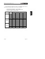
1
MO-170
MODULADOR COFDM DVB-T
DVB-T COFDM MODULATOR
- 0 MI1469 -
NOTAS SOBRE SEGURIDAD
Antes de manipular el equipo leer el manual de instrucciones y muy
especialmente el apartado PRESCRIPCIONES DE SEGURIDAD.
sobre el equipo significa "CONSULTAR EL MANUAL DE
El símbolo
INSTRUCCIONES". En este manual puede aparecer también como símbolo de
advertencia o precaución.
Recuadros de ADVERTENCIAS Y PRECAUCIONES pueden aparecer a lo largo de
este manual para evitar riesgos de accidentes a personas o daños al equipo u
otras propiedades.
SAFETY NOTES
Read the user’s manual before using the equipment, mainly " SAFETY RULES "
paragraph.
The symbol
on the equipment means "SEE USER’S MANUAL". In this
manual may also appear as a Caution or Warning symbol.
Warning and Caution statements may appear in this manual to avoid injury
hazard or damage to this product or other property.
SUMARIO
CONTENTS
English manual .............................................................
English
Manual español.............................................................
MANUAL DE INSTRUCCIONES. MO-170
Í N D I C E
1
GENERALIDADES .................................................................................................... 1
1.1 Descripción general............................................................................................. 1
1.2 Descripción funcional .......................................................................................... 2
1.3 Especificaciones.................................................................................................. 4
2
PRESCRIPCIONES DE SEGURIDAD ...................................................................... 7
2.1 Generales............................................................................................................ 7
2.2 Ejemplos Descriptivos de las Categorías de Sobretensión ................................ 9
3
INSTALACIÓN......................................................................................................... 11
3.1 Alimentación...................................................................................................... 11
3.1.1 Funcionamiento mediante conexión a la red eléctrica................................ 11
3.2 Instalación y Puesta en Marcha ........................................................................ 11
4
INSTRUCCIONES DE UTILIZACIÓN...................................................................... 13
4.1 Descripción del Panel Frontal ........................................................................... 13
4.2 Descripción del Panel Posterior ........................................................................ 14
4.3 Funciones del menú. ......................................................................................... 15
4.4 Funciones del MODULADOR............................................................................ 16
4.5 Funciones RF .................................................................................................... 20
4.6 Funciones de NIVEL ......................................................................................... 21
4.7 Funciones de TEST........................................................................................... 22
4.8 Funciones de CONFIGURACIÓN ..................................................................... 23
4.9 Control REMOTO vía interfaz RS-232 .............................................................. 25
4.10 Velocidades binarias útiles del estándar DVB-T ............................................... 30
4.11 Información sobre errores ................................................................................. 32
4.11.1 Tipos de errores .......................................................................................... 33
4.11.2 Codificación de los errores ......................................................................... 33
5 MANTENIMIENTO ..................................................................................................... 37
5.1 Sustitución del fusible........................................................................................ 37
5.2 Recomendaciones de Limpieza ........................................................................ 37
APÉNDICE A: Tablas de canales
MANUAL DE INSTRUCCIONES. MO-170
MANUAL DE INSTRUCCIONES. MO-170
MODULADOR COFDM DVB-T
MO-170
1
1 GENERALIDADES
1.1 Descripción general
El MO-170 es un modulador DVB-T de total compatibilidad con el estándar ETSI
EN 300 744 v1.5.1. La entrada del modulador es una trama de transporte MPEG-2 (TS)
en formato DVB-SPI ó DVB-ASI. Las salidas del equipo corresponden a señales
DVB-T moduladas en COFDM y convertidas a frecuencias FI y RF.
El MO-170 soporta los modos 2k y 8k, así como la transmisión jerárquica, y
puede ser utilizado en redes multifrecuencia (MFN). Tanto la codificación digital como
el proceso de modulación han sido implementados mediante dispositivos lógicos
programables basados en la propia tecnología de PROMAX. Esto le confiere un diseño
muy flexible, para adaptarse a cualquier aplicación en particular y ofrecer una gama
amplia de funciones a bajo coste.
Entre sus principales prestaciones destacan:
•
Operación en modo 2k y 8k
•
Soporta modos Jerárquicos
•
Funcionamiento en modo Master (maestro) y Slave (esclavo)
•
Anchos de banda de canal de 6, 7 y 8 MHz (seleccionable por el usuario)
•
Resolución alta en frecuencia (en pasos de 1 Hz)
•
MER elevado
1
12/2006
Trade Mark of the DVB Digital Video Broadcasting Project (4027).
Página 1
MANUAL DE INSTRUCCIONES. MO-170
1.2 Descripción funcional
El MO-170 es un modulador DVB-T de propósito general para montaje en rack
de 19 pulgadas. El equipo dispone de tres entradas TS MPEG-2 seleccionables (dos
entradas serie ASI y una entrada paralelo SPI). Cualquiera de estas entradas puede
ser utilizada para modular la señal COFDM tanto en modo jerárquico (una entrada TS)
como no jerárquico (dos entradas TS). El equipo permite generar internamente una
señal TS adicional para generar señales DVB-T incluso en ausencia de una entrada TS
válida.
En el modo esclavo (slave), la velocidad binaria de la trama de transporte (TS) de
entrada al modulador COFDM debe estar especificada en la norma ETSI EN 300 744
para cada configuración de parámetros de transmisión DVB-T. De esta forma, el
modulador podrá sincronizar automáticamente su reloj interno a la velocidad binaria del
TS de entrada. El modo esclavo permite utilizar una entrada de TS a velocidad binaria
constante en modo no jerárquico. Cuando utilice jerarquía, el usuario deberá escoger la
trama de transporte TS (HP ó LP) de la entrada que va a ser “mapeada”, y en
consecuencia, sincronizada por el modulador. La otra trama de transporte, se generará
internamente como un secuencia binaria pseudoaleatoria (PRBS).
La velocidad binaria de entrada en modo esclavo debe pertenecer a un margen
de valores del 0.1l respecto a los especificados por el estándar DVB-T (Ver apartado
“4.10 Velocidades binarias útiles del estándar DVB-T”) y aproximadamente constante.
Este modo de operación es especialmente útil cuando se remodula una señal DVB-T
sin transmitir, utilizando los mismos parámetros sin que sea necesidad de
demultiplexar y volver a multiplexar el flujo de transporte (como sería el caso del modo
maestro).
El margen de enganche para el MO-170 respecto a la velocidad del TS es mayor
a la de un demodulador COFDM. Esto es debido a que el modulador sincroniza
perfectamente en modo esclavo, mientras que un receptor DVB-T típico no es capaz
de adquirir el sincronismo.
En el modo maestro (master), el MO-170 es capaz de trabajar con cualquier
velocidad binaria de entrada que sea estrictamente menor que la velocidad binaria útil
especificada en el estándar DVB-T para la configuración DVB-T utilizada (Ver apartado
‘4.10 Velocidades binarias útiles del estándar DVB-T’). Es el propio modulador el que
se encarga de adaptar la velocidad binaria de entrada a la requerida por el modo
DVB-T en uso (bit rate adaptation). Para ello se añaden paquetes de relleno (packet
stuffing) a la trama de transporte MPEG-2. Con el fin de preservar la integridad de la
trama MPEG-2, los valores de los relojes de programa embebidos en la trama son
automáticamente re-estampados a su paso por el modulador (PCR restamping). En los
modos con jerarquía, el MO-170 en modo maestro presenta la ventaja sobre el modo
esclavo de poder utilizar cualquiera de las tres entradas TS como entrada de tramas de
alta prioridad (HP) o baja prioridad (LP) o ambas simultáneamente.
Página 2
12/2006
MANUAL DE INSTRUCCIONES. MO-170
El modulador puede ser configurado para generar cualquier modo de transmisión
incluido en las especificaciones DVB-T. En los modos jerárquicos, las tramas de
transporte HP y LP pueden ser codificadas convolucionalmente a diferente velocidad
binaria.
El ancho de banda es seleccionado por el usuario entre 6, 7 ó 8 MHz según
requiera la aplicación. El MO-170 ofrece varios modos de prueba (supresión de
portadoras, salida de un único tono, generación de patrones TS, inyección de CBER y
VBER).
El modulador es flexible en frecuencia. El usuario puede seleccionar una
frecuencia de salida entre 45 y 875 MHz por pasos de 1 Hz. Durante el funcionamiento
normal, la frecuencia de salida FI es ajustada internamente por el modulador, pudiendo
variar entre 31 y 36 MHz dependiendo de la frecuencia RF seleccionada. La salida RF
puede ser desconectada, en tal caso la frecuencia FI se fija a 36 MHz. La polaridad del
espectro FI/RF (invertido o no invertido) puede ser seleccionado por el usuario.
El MO-170 ha sido diseñado para trabajar con redes Multifrecuencia (MFN). La
operación en redes de Frecuencia Única (SFN) no está soportada actualmente. La
calidad de la salida de señal ha sido optimizada para los canales de 8 MHz. El MER
medido a FI, en este caso, es de aproximadamente 40 dB en modo maestro.
La supervisión y control del MO-170 se realiza a través de la pantalla LCD
situada en el panel frontal. El modulador se configura fácilmente mediante un conjunto
de menús de navegación muy intuitiva. Un par de indicadores luminosos situados en el
panel frontal señalan la existencia de errores en el modulador o si el equipo está
correctamente alimentado.
12/2006
Página 3
MANUAL DE INSTRUCCIONES. MO-170
1.3 Especificaciones
ENTRADAS
Trama de transporte MPEG-2
Modos de operación
Maestro
Esclavo
SALIDA FI
Tipo
Margen de frecuencia
Polaridad del espectro
Nivel de potencia (media)
Rizado de amplitud en la banda
Rizado retardo de grupo en banda
Estabilidad en frecuencia
Característica espectral
fuera de banda1
@ ± 3,805 MHz
@ ± 4,25 MHz
@ ± 5,25 MHz
Nivel de armónicos y espurios
MER2
Dos entradas DVB-ASI, 75 Ω BNC hembra
Una entrada DVB-SPI, LVDS DB-25
Paquetes TS de 188 ó
204 bytes de longitud (detección automática).
Soporta modo burst y paquetes continuos
Velocidad binaria TS estrictamente por debajo
de la norma DVB-T
Adaptación automática velocidad (Packetstuffing y PCR-stamping)
Velocidad binaria TS constante según norma
DVB-T, con tolerancia ±0,1‰
Conector 50 Ω BNC hembra
Ajustable entre 31 - 36 MHz por pasos de 1 Hz
Fija a 36 MHz con salida RF mute activada.
Seleccionable mediante controles del panel frontal
0 dBm (107 dBµV) fija
< 0,5 dB
< 10 ns
20 ppm
0 dBc
-39 dBc (2k), -47 dBc (8k)
-52 dBc
≤ -50 dBc
> 40 dB
1
Las frecuencias son relativas a la frecuencia central para un canal de 8 MHz. Los niveles de pico medidos
utilizando un ancho de banda de 10 kHz se refieren a las portadoras situadas en cualquier banda del espectro. Los
valores indicados son para el peor caso y corresponden a intervalos de guarda de 1/32.
2
Valor medido en modo maestro. En modo esclavo, el MER es mayor de 38 dB para canales de 8 MHz. Para
canales de 7 y 6 MHz el MER es de 35 dB aproximadamente.
Página 4
12/2006
MANUAL DE INSTRUCCIONES. MO-170
SALIDA RF
Tipo
Margen de frecuencia
Polaridad espectro
Nivel de potencia (media)
Estabilidad en frequencia
MER
Fase del ruido SSB
PARÁMETROS DVB-T
Tamaño IFFT
Intervalos de guarda
Tasa de código
Constelaciones
Modos jerárquicos
Operación MFN
Ancho de banda
MODOS DE TEST
Suprimir portadoras
Portadoras piloto
Portadora única
Paquetes test del TS
Secuencias PRBS
12/2006
Conector 50 Ω Tipo-N hembra
Ajustable entre 45 y 875 MHz por pasos de 1 Hz
Seleccionable mediante los controles del panel
frontal
Aproximadamente 80 dBµV sin atenuación.
Atenuación variable de 0 a 60dB en pasos de 1
dB
20 ppm
> 32 dB
≤ -87 dBc/Hz @ 2 kHz
2k, 8k
1/4, 1/8, 1/16, 1/32
1/2, 2/3, 3/4, 5/6, 7/8
QPSK, 16QAM, 64QAM
16QAM y 64QAM constelaciones con proporciones
de constelación α= 1, 2 ó 4
Disponible
6, 7 y 8 MHz (seleccionable por el usuario)
Suprime un número de portadoras (desde un
índice inicial a un índice final) del conjunto
COFDM. Permite medir el ruido de
intermodulación y de cuantificación de la banda
Genera únicamente las portadoras piloto
(continuas y TPS)
Genera una única portadora en la frecuencia
central cuyo nivel equivale a la potencia media
de salida COFDM o bien se fija en el máximo
disponible
Permite la calibración del nivel de señal
Genera internamente TS de test mediante
secuencias PRBS de longitud 15 ó 23 bits
integrados en paquetes NULL según norma
ETSI TR 101 290
Mapeado de una secuencia PRBS en los
puntos de constelación según norma
ETSI TR 101 290
Página 5
MANUAL DE INSTRUCCIONES. MO-170
Inyección de bits erróneos
Inyecta bits erróneos en la entrada del
mapeador de la constelación seleccionada
(produce un CBER <> 0 después del
descodificador de Viterbi) o en la entrada del
codificador de convolución (produce un VBER
<> 0 después del descodificador de Viterbi)
INTERFAZ RS-232C
ALIMENTACIÓN
Tensión
Frecuencia
Consumo
90 — 250 VAC
50 - 60 Hz
20 W
CONDICIONES AMBIENTALES DE FUNCIONAMIENTO
Uso en interiores
Altitud
Hasta 2000 mts
Margen de temperaturas
De 5° a 40°C
Humedad relativa máx.
80% (hasta 31° C), decreciendo linealmente
hasta el 50% a 40° C
CARACTERÍSTICAS MECÁNICAS
Dimensiones
Peso
482,6 (An.) x 44,4 (Al.) x 381 (Pr.) mm
6,3 kg
OPCIONES
OP-170-E
Generador de ruido blanco para comprobación del C/N. Simulación
de canales fijos y móviles en redes SFN/MFN.
OP-170-P
Amplificador de 10 dBm.
Página 6
12/2006
MANUAL DE INSTRUCCIONES. MO-170
2 PRESCRIPCIONES DE SEGURIDAD
2.1 Generales
*
*
*
*
Utilizar el equipo solamente en sistemas con el negativo de medida conectado
al potencial de tierra.
Este es un equipo de clase I, por razones de seguridad debe conectarse a lineas
de suministro con la correspondiente toma de tierra.
Este equipo puede ser utilizado en instalaciones con Categoría de Sobretensión II
y ambientes con Grado de Polución 1.
Al emplear cualquiera de los siguientes accesorios debe hacerse sólo con los tipos
especificados a fin de preservar la seguridad:
Cable de red
*
*
*
*
CA005
Tener siempre en cuenta los márgenes especificados tanto para la alimentación
como para la medida.
Recuerde que las tensiones superiores a 60 V DC o 30 V AC rms son
potencialmente peligrosas.
Observar en todo momento
especificadas para el aparato.
las
condiciones
ambientales
máximas
Operador solo está autorizado a intervenir en:
Cambio de fusibles que deberán ser del tipo y valor indicados.
En el apartado Mantenimiento se dan instrucciones específicas para estas
intervenciones.
Cualquier otro cambio en el equipo deberá ser efectuado exclusivamente por
personal especializado.
*
El negativo de señal se halla al potencial de tierra.
*
No obstruir el sistema de ventilación del equipo.
*
*
Utilizar para las entradas / salidas de señal, especialmente al manejar niveles altos,
cables apropiados de bajo nivel de radiación.
Seguir estrictamente las recomendaciones de limpieza que se describen en el
apartado Mantenimiento.
12/2006
Página 7
MANUAL DE INSTRUCCIONES. MO-170
*
Símbolos relacionados con la seguridad
CORRIENTE CONTINUA
CORRIENTE ALTERNA
ALTERNA Y CONTINUA
TERMINAL DE TIERRA
TERMINAL DE PROTECCIÓN
TERMINAL A CARCASA
EQUIPOTENCIALIDAD
MARCHA
PARO
DOBLE AISLAMIENTO
(Protección CLASE II)
PRECAUCIÓN
(Riesgo de choque eléctrico)
PRECAUCIÓN VER MANUAL
FUSIBLE
Página 8
12/2006
MANUAL DE INSTRUCCIONES. MO-170
2.2 Ejemplos Descriptivos de las Categorías de Sobretensión
Cat I
Instalaciones de baja tensión separadas de la red.
Cat II
Instalaciones domésticas móviles.
Cat III
Instalaciones domésticas fijas.
Cat IV
Instalaciones industriales.
12/2006
Página 9
MANUAL DE INSTRUCCIONES. MO-170
Página 10
12/2006
MANUAL DE INSTRUCCIONES. MO-170
3 INSTALACIÓN
3.1 Alimentación
El MO-170 es un equipo alimentado a través de la red eléctrica para su
operación.
3.1.1 Funcionamiento mediante conexión a la red eléctrica
Conectar el equipo a la red eléctrica a través del conector de tensión AC [12]
situado en el panel posterior del MO-170.
Verificar que la tensión eléctrica suministrada por la red es conforme a las
especificaciones del equipo.
3.2 Instalación y Puesta en Marcha
El modulador MO-170 está diseñado para su utilización como equipo de montaje
en Rack de 19” (chasis 1U)
Conmutar a la posición I (Encendido) el interruptor principal [13] situado en el
panel posterior. Tras una puesta en marcha con éxito, el equipo emite cuatro tonos
acústicos que indican que está preparado para iniciar la operación. Cuando el equipo
está conectado a la red, el indicador luminoso LINE [3] permanece encendido.
12/2006
Página 11
MANUAL DE INSTRUCCIONES. MO-170
Página 12
12/2006
MANUAL DE INSTRUCCIONES. MO-170
4 INSTRUCCIONES DE UTILIZACIÓN
ADVERTENCIA:
Las funciones que se describen a continuación podrían ser modificadas en función de
actualizaciones del software del equipo, realizadas con posterioridad a su fabricación y
a la publicación de este manual.
4.1 Descripción del Panel Frontal
1
2
3
4
5
Figura 1.- Panel frontal.
[1]
Pantalla LCD.
Con 2x40 caracteres de lectura fácil gracias a la retroiluminación a LEDs.
[2]
ERROR
LED ROJO realiza dos funciones. Durante cada segundo de funcionamiento, las
primeras décimas de segundo indica si el sistema está enganchado (OFF) o
desenganchado (ON).
Las restantes nueve décimas de segundo, el indicador luminoso en color rojo
muestra si se han detectado errores durante más de 5 segundos (ON) (desde la
última vez que el contador de errores fue reinicializado).
[3]
LINE
LED VERDE indicador que señala cuando la alimentación está ON.
[4]
MENU
La tecla de MENU permite al usuario entrar y salir de las funciones del menú, así
como modificar los parámetros funcionales del equipo (parámetros de
modulación, nivel y frecuencia de salida, y otras funciones de configuración).
12/2006
Página 13
MANUAL DE INSTRUCCIONES. MO-170
[5]
Selector rotativo y pulsador.
Posee múltiples funciones: Desplazamiento por los diferentes menús y submenús
que aparecen en el monitor y validación de las distintas opciones.
Cuando se pulsa el selector rotativo, y estamos modificando alguna función del
equipo, la opción que en ese momento visualice la pantalla LCD será
seleccionada. Girando el selector rotativo en sentido horario (CW) o antihorario
(CCW) permite navegar a través de las opciones disponibles en cada menú de
funciones del MO-170.
4.2 Descripción del Panel Posterior
El panel posterior muestra, de derecha a izquierda, el conector para la tensión
AC de red, la rejilla del ventilador, un conector DB-9 para control remoto vía puerto
COM RS-232C, una entrada de TS paralela, dos entradas DVB-ASI TS para
suministrar el TS en formato serie, una salida de señal FI de test (valor nominal 36
MHz) y la salida principal de RF, con el nivel y la frecuencia establecida por el usuario.
6
7
8
9
10
11
12 13
Figura 2.- Vista panel posterior.
[6]
Salida RF, 50Ω, conector Tipo-N hembra.
[7]
Salida FI, 50Ω, BNC hembra
[8]
Entrada ASI1, 75Ω, BNC hembra
Entrada número 1 DVB-ASI.
[9]
Entrada ASI2, 75Ω, BNC hembra.
Entrada número 2 DVB-ASI.
[10] Entrada TS paralela DB-25.
Entrada DVB-SPI.
[11] Conector RS-232C, DB-9
Conector DB-9 para control remoto vía puerto COM RS-232C
Página 14
12/2006
MANUAL DE INSTRUCCIONES. MO-170
[12] Conector Tensión AC
Permite la alimentación del equipo a través de la red eléctrica.
[13] Interruptor principal
Conecta o desconecta la alimentación principal del equipo.
NOTA:
El valor real de la frecuencia FI puede variar entre 31 y 36 MHz, de acuerdo
con el valor de la frecuencia RF. Cuando se precisa de una valor fijo de 36
MHz, el modulador debe configurarse para inhibir la salida RF, en el menú
RF.
4.3 Funciones del menú.
Tras la puesta en marcha, en la pantalla del panel frontal del equipo aparece
información relativa a los principales parámetros de funcionamiento, tal como se
muestra en el siguiente ejemplo:
FREQ: 650000000 Hz ATT: 10 dB
FFT:8K CONST:64QAM BW:8 MHz GUARD:1/4
FREQ: 650000000 Hz ATT: 10 dB
TEST: NONE TS: Master (204)
Aquí la frecuencia RF es de 650 MHz, el atenuador RF por pasos de 1 dB ha sido
ajustado a incrementos de 10 dB, la señal DVB-T contiene 8K portadoras, ocupa 8
MHz y utiliza una constelación 64 QAM con intervalo de guarda de 1/4. No ha sido
seleccionado ningún modo de test (NONE) y el modo de operación establecido es el
modo maestro. Se han detectado paquetes de longitud 204 bytes en la entrada TS
seleccionada por el usuario.
Después de unos segundos, la pantalla cambia su contenido para mostrar el
tiempo de funcionamiento y la información relativa al cómputo de errores como se
muestra a continuación:
MO-170 PROMAX ELECTRONICA, S.A.
Working: 01:13:55 ERR: 0
El texto de línea de superior (nombre de la compañía por ejemplo) puede ser
modificada vía puerto RS-232 según las necesidades de cada usuario, permitiendo
fácilmente una identificación o aviso del equipo.
12/2006
Página 15
MANUAL DE INSTRUCCIONES. MO-170
Pulsando la tecla MENU, permite acceder al nivel principal del menú. Pulsar
MENU de nuevo para acceder a la pantalla principal de estado. Este nivel principal del
menú utiliza la primera línea de texto para proporcionar algunos avisos a cerca de las
operaciones asignadas a cada control, y la segunda línea de la pantalla sobre las
opciones y funciones seleccionables.
MENU: back PUSH: select TURN: next/prev.
MODULATOR
Al girar el selector rotativo CW o CCW, cambia el título del submenú entre:
1.
MODULADOR
2.
RF
3.
NIVEL
4.
TEST
5.
CONFIGURACIÓN
4.4 Funciones del MODULADOR
En este nivel del menú, los parámetros del modulador pueden ser modificados y
ajustados según los requisitos del usuario. Al modificar cualquier parámetro de
modulación, los cambios se activan sólo cuando se confirman pulsando el selector
rotativo. Por el contrario, pulsando la tecla de MENU, se cancela el cambio de la
opción. A continuación se comenta cada función:
TS HP Input: Permite seleccionar la entrada utilizada para suministrar el Transport
Stream (TS) de alta prioridad al modulador COFDM. Las opciones son:
ASI1:
Utiliza el TS suministrado por el conector de entrada ASI1 (panel
posterior).
ASI2:
Utiliza el TS suministrado por el conector de entrada ASI2 (panel
posterior).
SPI:
Utiliza el TS paralelo suministrado por el conector SPI (panel posterior).
PRBS:
Utiliza datos aleatorios generados internamente (PRBS) para generar paquetes
TS de prueba.
TS LP Input: Permite seleccionar la entrada utilizada para suministrar el Transport
Stream (TS) de baja prioridad al modulador COFDM. Las opciones son:
ASI1:
Utiliza el TS suministrado por el conector de entrada ASI1 (panel
posterior).
ASI2:
Utiliza el TS suministrado por el conector de entrada ASI2 (panel
posterior).
Página 16
12/2006
MANUAL DE INSTRUCCIONES. MO-170
SPI:
Utiliza el TS paralelo suministrado por el conector SPI (panel posterior).
PRBS:
Utiliza datos aleatorios generados internamente (PRBS) para generar
paquetes TS de prueba.
BW: Esta opción habilita la selección del ancho de banda. La señal COFDM puede
ser generada con un ancho de banda de 6 MHz, 7 MHz ó 8 MHz.
8 MHz:
Selecciona el ancho de banda de 8 MHz.
7 MHz:
Selecciona el ancho de banda de 7 MHz.
6 MHz:
Para un ancho de banda de 6 MHz.
Hierarchy: Utilizando esta función el modulador COFDM conmuta entre modo
jerárquico, con diferentes ratios de constelación alfa, y el modo de funcionamiento
no jerárquico. Las opciones disponibles son:
OFF:
Funcionamiento no jerárquico.
a=1:
Modo jerárquico con alfa = 1
a=2:
Modo jerárquico con alfa = 2
a=4:
Modo jerárquico con alfa = 4
HP Code Rate: Utilizando esta función, el usuario puede modificar la tasa de
código de modulación para los flujos de datos (TS) de alta prioridad (HP). Las
opciones disponibles son las siguientes:
• 1/2
• 2/3
• 3/4
• 5/6
• 7/8
LP Code Rate: Utilizando esta función, el usuario puede modificar la tasa de
código de modulación para los flujos de datos (TS) de baja prioridad (LP). Las
opciones disponibles son las siguientes:
• 1/2
• 2/3
• 3/4
• 5/6
• 7/8
12/2006
Página 17
MANUAL DE INSTRUCCIONES. MO-170
Constellation: Aquí el menú permite seleccionar una de las constelaciones de
modulación disponibles. Las opciones son:
• QPSK
• 16QAM
• 64QAM
Guard Interval: Esta función se utiliza para seleccionar el intervalo de guarda
requerido de la señal COFDM. Los valores disponibles son:
• 1/4
• 1/8
• 1/16
• 1/32
FFT Mode: Selección del valor FFT requerido (número de portadoras en el
conjunto COFDM). El modulador tiene las siguientes opciones:
• 2K
• 8K
Spectral Inversion: Esta función permite realizar la inversión del espectro
generado tanto para la FI como en RF. Dado que el espectro FI está invertido en
comparación con la salida RF, el concepto de inversión se refiere a la salida RF.
Las opciones posibles son:
• OFF:
Las portadoras con los índices menores ocupan las frecuencias más
bajas del canal RF.
• ON:
Las portadoras con los índices mayores ocupan las frecuencias más
bajas del canal RF.
PRBS bits: Selección de la longitud en bits de la secuencia pseudoaleatoria que
genera internamente:
• 23:
Secuencia PRBS de longitud 2²³-1 como se documenta en el TR 101
290.
• 15:
Secuencia PRBS de longitud 2¹⁵-1 como se documenta en el TR 101
290.
Página 18
12/2006
MANUAL DE INSTRUCCIONES. MO-170
TS sync mode: Selecciona el modo de operación del modulador respecto al TS de
entrada (Ver el apartado 1.2 para más detalles):
• Master
• Slave
Slave mode TS lock: En modo esclavo, selecciona la entrada TS respecto a la que
el modulador sincroniza su reloj interno. Las opciones posibles son:
• HP:
El modulador está sincronizado con el TS HP.
• LP:
El modulador está sincronizado con el TS LP (sólo modos jerárquicos).
Test Opt: Selecciona el test a realizar. Las opciones disponibles son:
NONE: Salida COFDM normal.
CBER: Inyecta bits de error en el canal para obtener un BER diferente de cero
antes del decodificador de Viterbi (Channel BER).
VBER: Inyecta bits de error para obtener un BER después del decodificador de
Viterbi (Viterbi BER o simplemente BER) diferente de cero.
Blank carriers: Inicia la supresión de portadoras en el índice de portadora
inicial (Start Carrier) y la finaliza en el de portadora final (Stop Carrier) (Ver
apartado “4.7 Parámetros de Test”).
Pilots only: Genera una señal DVB-T que contiene sólo portadoras piloto
(continua y TPS).
PRBS/TR 290: Sustituye la entrada al mapeador de la constelación por una
secuencia pseudoaleatoria (PRBS) de longitud 2¹⁵ -1 ó 2²³-1 (Consultar la
función Bits PBRS comentada anteriormente) tal como se especifica en el
documento ETSI TR 101 290.
12/2006
Página 19
MANUAL DE INSTRUCCIONES. MO-170
4.5 Funciones RF
La selección de este ítem permite acceder a las funciones relativas a la salida
RF. A continuación se repasan las opciones disponibles:
Frecuencia: Esta función permite la selección de la frecuencia RF. Los cambios
realizados mediante el selector rotativo se aplican directamente a la salida,
permitiendo una sintonización precisa de la frecuencia de salida deseada.
Al acceder a la función, la pantalla muestra la frecuencia actual y la variación que
se introduce al modificarla cuando se gira el selector rotativo. Los pasos de frecuencia
son increméntales al girar el selector rotativo en sentido horario y decrementales al
girarlo en sentido antihorario.
MENU: back PUSH: select TURN: next/prev.
RF Frequency: 650000000 Hz <10MHz>
En este caso, la frecuencia de salida actual es de 650 MHz y girando un paso en
sentido horario (cada paso se señala mediante un tono acústico) cambiará el valor a
660 MHz.
En esta situación, cada vez que se pulse el selector rotativo, el paso de variación
de frecuencia se modificará de 1 MHz, 100 kHz, 10 kHz, 1 kHz, 100 Hz, 10 Hz, 1 Hz y
otra vez 10 MHz, de forma cíclica permitiendo la selección del valor deseado.
Para abandonar esta función, se debe pulsar la tecla MENU.
Canal: Una sintonización rápida de la frecuencia de salida puede realizarse
utilizando el conjunto de listas de canales incluidas en el MO-170. Esto permite la
selección directa de las frecuencias estándar utilizadas en la mayoría de países.
Al acceder a esta función, se visualiza secuencialmente la lista de todos los
canales disponibles. Girando el selector rotativo se puede seleccionar el que se desee.
Pulsar el selector para abandonar la función.
La lista de canales se seleccionan a partir del conjunto de listas de canales ya
incluidas en el equipo. Las listas de canales disponibles se visualizan y seleccionan
desde el menú CONFIGURACIÓN, como se verá más adelante.
También en este caso, los cambios de frecuencia se aplican inmediatamente a la
etapa RF, permitiendo un ajuste interactivo de la frecuencia.
Esta lista de planes de canales puede ser consultada en el apéndice A.
Página 20
12/2006
MANUAL DE INSTRUCCIONES. MO-170
Deshabilitar: Esta opción permite deshabilitar la salida de RF. Esto se consigue
introduciendo una fuerte atenuación (aproximadamente 80 dB) en la señal RF.
Simultáneamente, la frecuencia FI se sintoniza al valor nominal de 36 MHz. Los
valores seleccionables son:
• NO
• YES
4.6 Funciones de NIVEL
Esta opción del menú principal incluye las funciones relativas al ajuste del nivel
de RF. El MO-170 cuenta con un atenuador programable integrado de 60 dB en pasos
de 1 dB. Simultáneamente el nivel de RF nominal puede ser ajustado con detalle
mediante el control de ganancia del amplificador RF, aplicando los incrementos de 1 dB
de la atenuación a partir del valor de referencia.
La estructura de ganancia RF puede ser controlada mediante las siguientes
funciones.
Atenuación: Esta función permite seleccionar el nivel de salida RF aplicando
pasos de atenuación de 1 dB, desde 0 dB hasta 60 dB. Girando el selector rotativo
en sentido horario se incrementa la atenuación, reduciendo el nivel de salida.
Girando en sentido antihorario produce el efecto contrario.
Los cambios son aplicados de forma inmediata a la salida RF para facilitar un
ajuste sencillo y preciso de la salida RF. Pulsar el selector rotativo o la tecla MENU
para abandonar esta función.
Ajuste fino de ganancia RF: Seleccionar esta función para programar la salida de
nivel de referencia RF máximo. Para una correcta referencia, ajustar la atenuación
de salida a 0 dB, antes de modificar este ajuste.
Los cambios también se aplican en tiempo real. Girar el selector rotativo en
sentido horario para incrementar el nivel de salida. Girar en sentido antihorario para
disminuir el nivel.
Los caracteres visualizados son números enteros. El margen oscila entre un valor
máximo de atenuación de —31 hasta un valor mínimo de +31 (es decir, desde 0 hasta
63 pasos de atenuación).
Para salir de esta función, pulsar la tecla de MENU o el selector rotativo.
12/2006
Página 21
MANUAL DE INSTRUCCIONES. MO-170
4.7 Funciones de TEST
Este menú contiene una serie de parámetros a definir para realizar correctamente
las diferentes pruebas de transmisión mediante el modulador MO-170.
MODO: Selecciona el test a realizar. Las opciones disponibles son:
NONE: Salida COFDM normal.
CBER: Inyecta bits de error en el canal para obtener un BER diferente de
cero antes del decodificador de Viterbi (Channel BER).
VBER: Inyecta bits de error para obtener un BER después del
decodificador de Viterbi (Viterbi VER o simplemente VER) diferente de
cero.
Blank carriers: Inicia la supresión de portadoras en el índice de portadora
inicial (Start Carrier) y la finaliza en el de portadora final (Stop Carrier) (Ver
siguiente parágrafo).
Pilots only: Genera una señal DVB-T que contiene sólo portadoras piloto
(continua y TPS).
PRBS/TR 290: Sustituye la entrada al mapeador de la constelación por una
secuencia pseudoaleatoria (PRBS) de longitud 2²³ -1 ó 2²³-1 (Consultar la
función Bits PBRS comentada anteriormente) tal como se especifica en el
documento ETSI TR 101 290.
Los siguientes dos parámetros seleccionan el intervalo de portadoras a suprimir,
con el fin de realizar las medidas del ruido de intermodulación y/o cuantificación dentro
del canal.
Portadora inicial: Establece el índice inicial (de 0 a 1704 en 2k, 0 a 6816 en
8k) de la primera portadora a suprimir del conjunto de portadoras COFDM.
Portadora final: Establece el índice final (de 0 a 1704 en 2k, 0 a 6816 en 8k)
de la última portadora a suprimir del conjunto de portadoras COFDM.
Estos dos parámetros siguientes permiten seleccionar el intervalo de portadoras
que se desean suprimir para realizar las medidas del ruido de intermodulación o
cuantificación en la banda.
Valor del CBER: Proporción de bits erróneos a inyectar en la entrada del
mapeador de puntos de la constelación. Esto provoca un CBER <> 0 después
del descodificador de Viterbi (valores entre 7,6E-6 y 1,2E-1).
Valor del VBER: Proporción de bits erróneos a inyectar en la entrada del
codificador de convolución. Esto provoca VBER <> 0 después del decodificador
de Viterbi (valores entre 3,7E-9 y 6,2E-2).
Página 22
12/2006
MANUAL DE INSTRUCCIONES. MO-170
4.8 Funciones de CONFIGURACIÓN
En este menú contiene un conjunto de funciones relativas a la configuración y
ajuste del instrumento completo.
Guardar en memoria: El MO-170 incorpora una serie de memorias de
configuración que permiten almacenar tanto los parámetros del modulador como
los valores del nivel y la frecuencia RF.
Para guardar la configuración actual, girar el selector rotativo y seleccionar la
posición de memoria deseada (de la 0 a la 10). Pulsar el selector rotativo para
confirmar la acción de guardar. Pulsar la tecla MENU para cancelar la acción.
Esta función, al igual que la de recuperación de datos, incrementa
automáticamente la posición de memoria, para permitir guardar y recuperar más
fácilmente las posiciones de memoria consecutivas.
Carga de la memoria: Esta es la función dual respecto a la anterior.
Seleccionando la posición de memoria deseada, permite cargar una configuración
completa del equipo.
Lista de canales: Utilizar esta función para escoger entre las diferentes tablas de
canales incluidas en el MO-170. Las tablas de canales disponibles (una lista
ordenada de frecuencias de canales) proceden de las listas de canales analógicos
estándar. También se incluye una lista de todos los canales existentes al final de
este documento. (Ver apéndice A)
Las selecciones visualizadas por medio del selector rotativo son:
CCIR
(principal estándar de Europa Occidental)
STD L
(estándar francés)
OIRT
(estándar Europa oriental)
UHF
(sólo la parte UHF de la CCIR, para selección rápida)
Modo FI: Utilizando esta función, el usuario puede seleccionar generar una señal
COFDM o un único tono. Un único tono puede ser útil para una alineación precisa o
la comprobación de componentes externos. Las opciones disponibles son:
• COFDM:
Genera una señal DVB-T COFDM.
• TONE MAX
Genera un único tono con el nivel máximo disponible para el
MO-170.
• TONE RMS
Genera un único tono con el nivel medio equivalente a la potencia
RMS de la señal modulada en COFDM.
12/2006
Página 23
MANUAL DE INSTRUCCIONES. MO-170
Lista de errores: Durante el funcionamiento continuo del MO-170, los primeros 16
errores detectados son guardados como una referencia para identificar las causas
del problema. Habitualmente, no se producen errores y en la pantalla aparece:
MENU: back PUSH: select TURN: next/prev.
NO ERRORS
Pero, durante el funcionamiento pueden producirse, fundamentalmente, dos tipos
de errores (Ver apartado ‘4.11 Información sobre errores’):
• Errores generados cuando se detecta el estado desenganchado del modulador
respecto a la entrada TS seleccionada.
Estos son habitualmente errores temporales relativos a las transiciones del flujo
de datos de entrada o una velocidad binaria del TS no válida.
• Errores generados debido a un fallo del circuito. Cuando este tipo de errores
persiste, los instrumentos deben ser remitidos a un centro oficial PROMAX.
Ver el apartado 4.11 para una explicación en detalle del formato utilizado para
mostrar los errores.
Borrar Errores: Seleccionar esta función para borrar el contador de errores
internos y la lista de errores descrita anteriormente.
• NO
• Sí
Firmware: Indica la versión del firmware incluida en el equipo. A continuación se
muestra un ejemplo de esta pantalla:
MENU: back PUSH: select TURN: next/prev.
CONFIGURATION Firmware: v1.0.02 - 84.00
Página 24
12/2006
MANUAL DE INSTRUCCIONES. MO-170
4.9 Control REMOTO vía interfaz RS-232
El MO-170 dispone de un puerto serie compatible RS-232C para el control
remoto a través de un ordenador. Un conjunto adecuado de comandos de control
permiten averiguar y modificar cualquier parámetro funcional.
Detalles de la comunicación: Hay un protocolo de control para sincronizar la
recepción de comandos y su validación. Debe enviarse un comando cada vez que un
carácter XON (código 0x11: valor hexadecimal 11 o 17 en decimal) se recibe del
instrumento. Cuando el instrumento detecta un comando completo, envía un código
XOFF (0x13) y, una vez validado y ejecutado, un código ACK (0x06) o NAK (0x15) es
enviado al controlador remoto.
Para asegurar una comunicación libre de errores entre los dos dispositivos,
deben ser introducidos los siguientes parámetros de comunicación en el controlador
remoto del puerto serie:
Rate: 19200 bauds Data bits: 8 bits Parity: None Stop bits: 1
El MO-170 acepta comandos remotos en cualquier momento, cuando el
instrumento se enciende. No es necesario poner el equipo en un modo especial de
control remoto. La comunicación se realiza utilizando las líneas de datos del transmisor
y receptor en el puerto serie. También las señales de control CTS y RTS deben ser
conectadas.
Un cable de conexión serie NULL MODEM DB9 a DB9 para ordenadores PC
estándar.
El protocolo de comunicación es el siguiente:
1) MO-170 transmite un código XON (11H) cada segundo. El objetivo es indicar a
cualquier posible dispositivo remoto que los equipos están preparados para recibir
datos.
2) En este momento, el flujo de datos puede ser enviado. Cada flujo de datos se
compone de:
• Carácter inicial ‘∗’ (código 0x2A)
• Conjunto de caracteres que describen el mensaje de datos.
• Carácter final CR (retorno del carro, código 0x 0D)
3) Una vez el flujo de datos ha sido enviado, se recibirá un XOFF, indicando que la
transmisión de cualquier nuevo comando deberá esperar hasta completar el actual.
4) A continuación, si el formato del mensaje es correcto y su ejecución no tiene
errores, debe esperarse un ACK (acknowledge).
12/2006
Página 25
MANUAL DE INSTRUCCIONES. MO-170
5) Si el mensaje requiere una respuesta, será enviada en este momento.
6) Una vez finalizado el procesamiento del mensaje, el MO-170 enviará un XON
indicando que está preparado para recibir un nuevo comando.
Un cronograma típico de comunicación se describe a continuación:
PC
1) ⇐ XON
2)*?NA<cr> ⇒
3) ⇐ XOFF
4) ⇐ ACK
5) wait ...
6) ⇐ *NAMO-170<cr>
7) wait ...
8) ⇐ XON
MO-170
(equipo preparado para recibir comandos)
(comando transmitido por el controlador)
(indicación de comando recibido)
(comando aceptado / entendido)
(retardo de ejecución)
(enviar respuesta)
(habitualmente un pequeño retardo)
(equipo preparado para transmitir comandos)
(Todos los caracteres se transmiten en código ASCII)
Los comandos deben ser enviados siempre en letras mayúsculas y no pueden
ser editados en línea, por ejemplo, cuando un carácter se recibe es almacenado en el
búfer del MO-170 y no puede ser rectificado enviando un código de borrado.
En el modo de comunicación idle (el MO-170 espera recibir comandos) el equipo
enviará un código XON en intervalos de un segundo, para permitir la sincronización.
Lista de comandos: Los comandos se clasifican entre comandos de control y de
interrogación. Se inician enviando un carácter “*”, tienen formato de texto ASCII y
siempre comparten la misma estructura. Por ejemplo, el nombre del modelo del equipo
puede ser interrogado enviando “*?NA<cr>” y la respuesta será “*NAMO-170” (siempre
sin comillas) Se puede realizar un análisis de la respuesta para recuperar los datos
deseados del texto (en este caso “MO-170”).
Página 26
12/2006
MANUAL DE INSTRUCCIONES. MO-170
A continuación se muestra una tabla con todos los comandos disponibles.
Nombre Mensaje
Respuesta
Descripción y Formato
NAM
VER
BEP
*?NAM<cr>⇒
*?VER<cr>⇒
*BEP<cr>
*USRtext<cr>
⇐*NAMMO-170<cr>
⇐*VERv0.7.10<cr>
*?USR<cr>
*STOnn<cr>
*USRtext<cr>
STO
RCL
*RCLnn<cr>
Recupera el modelo del equipo
Recupera la versión del SW
Indicación acústica
Fija un nuevo texto de USUARIO para ser
visualizado en el panel LCD.
‘text’ es un texto ASCII con un máximo de 32
caracteres
Devuelve el texto USUARIO actual
Guarda la configuración actual en memoria.
´nn´ es un valor decimal de 00 a 10
Recupera una configuración desde memoria.
´nn´ es un valor decimal de 00 a 10.
Modifica la frecuencia RF del equipo.
´nn…n´ es el valor de frecuencia en Hz.
Expresado con 9 dígitos, desde 45 a 875MHz.
Devuelve la frecuencia actual RF en Hz y con 9
dígitos (rellenando con ‘0’ a la izquierda).
Cambia la atenuación de la salida RF.
‘nn’ es el nuevo valor decimal de atenuación en
dB.
Recupera el valor de atenuación RF actual.
valor ‘nn’ utilizando 2 dígitos decimales.
(rellenando con ‘0’ a la izquierda).
Recupera el contador de errores internos.
‘nn…n’ valor utilizando 8 dígitos decimales.
(rellenando con ‘0’ a la izquierda)
Borra el contador de errores interno.
USR
*FRQnn…n<cr>
FRQ
*?FRQ<cr>
*FRQnn…n<cr>
*ATTnn<cr>
ATT
*?ATT<cr>
*ATTnn<cr>
*?ERN<cr>
*ERNnn…n<cr>
ERN
ERC
*ERC<cr>
ERL
*?ERLnn<cr>
*ERLtext<cr>
LCK
*?LCK<cr>
*LCKchh<cr>
*MIHd<cr>
MIH
*?MIH<cr>
*MIHd<cr>
*MILd<cr>
MIL
*?MIL<cr>
*MILd<cr>
*MBWd<cr>
MBW
12/2006
*?MBW<cr>
*MBWd<cr>
Recupera un mensaje de error.
‘nn’ es el índice de error en valor decimal.
‘text’ es la cadena de texto en formato ASCII.
Recupera un mensaje de error.
‘c’ es el resultado del test de enganche: ‘L’ para
enganchado, ‘U’ para desenganchado ‘hhhh’
es un valor hexadecimal correspondiente al
código de estado (Ver apartado 4.11 para
códigos de error)
Fija la entrada del TS HP del modulador
al dígito decimal ‘d’
0:ASI1 1:ASI2 2:SPI 3:TEST
Pregunta por la entrada de TS HP actual del
modulador .
‘d’ como antes.
Fija la entrada del LP TS del modulador
al dígito decimal ‘d’
0:ASI1 1:ASI2 2:SPI 3:TEST
Pregunta por la entrada de TS HP actual del
modulador
Fija la salida BW del modulador al dígito
decimal ‘d’
0: 8MHz, 1: 7MHz, 2: 6MHz.
Pregunta por la salida BW del modulador
actual.
‘d’ como antes..
Página 27
MANUAL DE INSTRUCCIONES. MO-170
Nombre Mensaje
Respuesta
*MHId<cr>
MHI
*?MHI<cr>
*MHId<cr>
*MTPd<cr>
MTP
*?MTP<cr>
*MTPd<cr>
*HCRd<cr>
HCR
*?HCR<cr>
*HCRd<cr>
*LCRd<cr>
LCR
*?LCR<cr>
*LCRd<cr>
*MCOd<cr>
MCO
*?MCO<cr>
*MCOd<cr>
*MGUd<cr>
MGU
*?MGU<cr>
*MGUd<cr>
*FFTd<cr>
FFT
*?FFT<cr>
*FFTd<cr>
*INVd<cr>
INV
*?INV<cr>
*INVd<cr>
*MODd<cr>
MOD
*?MOD<cr>
*MODd<cr>
*FIFnn…n<cr>
FIF
*?FIF<cr>
*FIFnn…n<cr>
*DISd<cr>
DIS
Página 28
*?DIS<cr>
*DISd<cr>
Descripción y Formato
Fija el modo de jerarquía del modulador. ‘d’
dígito decimal 0: NO, 1: α=1, 2: α=2, 3: α=4
Pregunta por actual modo de jerarquía del
modulador. ‘d’ como antes.
Configura el modo de test del modulador.
‘d’ dígito decimal 0: NINGUNO, 1: CBER,
2: VBER, 3: BlkCar, 4: PILOTS, 5:PRBS
Pregunta por el actual modo de test.
‘d’ como antes.
Establece la velocidad de transmisión de
prioridad alta del TS del modulador.
‘d’ dígito decimal 0:1/2 1:2/3, 2:3/4, 3:5/6, 4:7/8
Pregunta sobre el CR actual del TS de alta
prioridad.
‘d’ como antes.
Establece la velocidad de transmisión de
prioridad baja del TS del modulador.
‘d’ dígito decimal 0:1/2 1:2/3, 2:3/4, 3:5/6, 4:7/8
Pregunta sobre el CR actual del TS de baja
prioridad.
‘d’ como antes.
Configura la constelación del modulador.
‘d’ dígito decimal 0:QPSK, 1:16QAM, 2:64QAM
Pregunta por la constelación actual del
modulador.
‘d’ como antes.
Configura el intervalo de guarda del modulador.
‘d’ dígito decimal 0:1/4, 1:1/8, 2:1/16, 3:1/32
Pregunta sobre el intervalo de guarda actual del
modulador. ‘d’como antes.
Configura el modo FFT del modulador.’d’ digito
decimal 0:2K, 1:8K.
Pregunta sobre el modo actual FFT del
modulador.
‘d’ como antes.
Configura el modo de inversión de espectro.
‘d’ dígito decimal 0:INV, 1:NO INV.
Pregunta sobre el modo actual de inversión de
espectro.
‘d’ como antes.
Configura el modo de salida FI del modulador.
‘d’ dígito decimal 0: COFDM, 1: TONO MAX,
2: TONO RMS
Pregunta sobre el modo de salida FI actual del
modulador. ‘d’ como antes.
Modifica la frecuencia FI del equipo.
´nn…n´ es el valor de frecuencia en Hz, escrito
con 8 dígitos, de 31 a 37 MHz.
Retorna la frecuencia FI actual en Hz y con 8
dígitos (rellenando con ‘0’ a la izquierda)
Deshabilita la salida RF. ‘d’ dígito decimal
0:HABILITA RF, 1:DESHABILITA RF
Pregunta sobre el estado deshabilitado del RRF
actual. ‘d’ como antes.
12/2006
MANUAL DE INSTRUCCIONES. MO-170
Nombre Mensaje
Respuesta
*MPRd<cr>
MPR
*?MPR<cr>
*MPRd<cr>
*MREd<cr>
MRE
*?MRE<cr>
*MREd<cr>
*MTSd<cr>
MTS
*?MTS<cr>
*MTSd<cr>
*MSSd<cr>
MSS
MPL
*?MSS<cr>
*MSSd<cr>
*?MPL<cr>
*MPLhhh/III<cr> ó
*MPLhhh<cr>
*MIIdddd<cr>
MII
*?MII<cr>
*MIIdddd<cr>
*MFIdddd<cr>
MFI
*?MFI<cr>
*MFFIdddd<cr>
*MCBddddddd<cr>
MCB
*?MCB<cr>
*MCBdddddddd<cr>
*MVBdddddddddd<cr>
MVB
*?MVB<cr>
12/2006
*MVBdddddddddd<cr>
Descripción y Formato
PRBS de 15 ó 23 bits
‘d’ dígito decimal 0: 15 bits PRBS, 1: 23 bits PRBS
Pregunta por la longitud PRBS actual con ‘d’
como antes.
Reestampado (modo maestro) del PCR
‘d’ dígito decimal 0: ON, 1: OFF
Pregunta por el estado de estampación actual
con ‘d’ como antes.
Modo Maestro ó Esclavo de enganche del TS
‘d’ dígito decimal 0: SLAVE, 1: MASTER
Pregunta por el modo de enganche actual con
‘d’ como antes.
TS activo en modo Esclavo
‘d’ dígito decimal 0: HP, 1: LP
Pregunta por el TS activo en modo esclavo
‘d’ como antes.
Pregunta por la longitud del paquete TS
detectado
‘hhh’ y ’III’ texto ASCII
hhh,III: 188 ó 204 bytes para TS HP/LP (LP
sólo en modo jerárquico)
Índice de la portadora inicial para el modo de
prueba de supresión de portadoras.
‘dddd’ dígitos decimales (0000 a 6816 @ 8k,
1704 @ 2k)
Pregunta por el valor del índice de la portadora
inicial.
‘dddd’ como antes.
Índice de la portadora final para el modo de
prueba de supresión de portadoras.
‘dddd’ dígitos decimales (0000 a 6816 @ 8k,
1704 @ 2k)
Pregunta por el valor del índice de la portadora
final.
‘dddd’ como antes.
Valor CBER generado en modo de test
‘ddddddd’ dígitos decimales
ddddddd = CBER x 1E7
Pregunta por el valor actual del CBER
‘ddddddd’ como antes
Valor VBER generado en modo de test
‘dddddddddd’ dígitos decimales
dddddddddd = VBER x 1E10
Pregunta por el valor actual del VBER
‘dddddddddd’ como antes
Página 29
MANUAL DE INSTRUCCIONES. MO-170
4.10 Velocidades binarias útiles del estándar DVB-T
A continuación se describen las tasas binarias útiles (Mbits/s ó Mbps) para todas
las combinaciones de intervalo de guarda, constelación y tasa de código convolucional
en sistemas DVB-T y canales de 8, 7 y 6 MHz. La velocidad binaria útil nunca depende
del modo de transmisión (2k ó 8k).
Estas tablas son similares a las Tablas 17 (8 MHz), E.6 (7 MHz) y E.3 (6 MHz)
del estándar DVB-T ETSI EN 300 744 v1.5.1 (2004-11), pero con 7 decimales de
precisión en lugar de 2 ó 3. Esta precisión adicional es necesaria ya que la velocidad
binaria de las tramas de transporte de entrada al modulador en el modo de operación
esclavo debe desviarse como máximo un ±0,1‰ de los valores indicados a
continuación, para garantizar así, que el modulador se enganche. Por ejemplo, para
QPSK, tasa 1/2 e intervalo de guarda 1/4, la velocidad binara útil del sistema DVB-T
para canales de 8 MHz es de 4,9764706 Mbps, por lo que en el modo esclavo la
velocidad de entrada de la trama de transporte a la que debe engancharse el
modulador debe ser mayor que 4,975973 Mbps y menor que 4,976968 Mbps.
Constelación Código
conv.
QPSK
16QAM
64QAM
Intervalo de guarda
1/4
1/8
1/16
1/32
1/2
4,9764706
5,5294118
5,8546713
6,0320856
2/3
6,6352941
7,3725490
7,8062284
8,0427807
3/4
7,4647059
8,2941176
8,7820069
9,0481283
5/6
8,2941176
9,2156863
9,7577855
10,0534759
7/8
8,7088235
9,6764706
10,2456747 10,5561497
1/2
9,9529412
11,0588235 11,7093426 12,0641711
2/3
13,2705882 14,7450980 15,6124567 16,0855615
3/4
14,9294118 16,5882353 17,5640138 18,0962567
5/6
16,5882353 18,4313725 19,5155709 20,1069519
7/8
17,4176471 19,3529412 20,4913495 21,1122995
1/2
14,9294118 16,5882353 17,5640138 18,0962567
2/3
19,9058824 22,1176471 23,4186851 24,1283422
3/4
22,3941176 24,8823529 26,3460208 27,1443850
5/6
24,8823529 27,6470588 29,2733564 30,1604278
7/8
26,1264706 29,0294118 30,7370242 31,6684492
Tabla 1.- Velocidad binaria útil (Mbps) para modos DVB-T y canales de 8 MHz.
Página 30
12/2006
MANUAL DE INSTRUCCIONES. MO-170
Para modulaciones jerárquicas de 8 MHz, las velocidades binarias útiles se
pueden obtener a partir de la Tabla 1 como se indica a continuación:
-
Secuencia de alta prioridad (HP) : valores de QPSK
-
Secuencia de baja prioridad (LP), 16QAM : valores de QPSK
-
Secuencia LP, 64QAM : valores de 16QAM
Constelación Código
conv.
QPSK
16QAM
64QAM
Intervalo de guarda
1/4
1/8
1/16
1/32
1/2
4,3544118
4,8382353
5,1228374
5,2780749
2/3
5,8058824
6,4509804
6,8304498
7,0374332
3/4
6,5316176
7,2573529
7,6842561
7,9171123
5/6
7,2573529
8,0637255
8,5380623
8,7967914
9,2366310
7/8
7,6202206
8,4669118
8,9649654
1/2
8,7088235
9,6764706
10,2456747 10,5561497
2/3
11,6117647 12,9019608 13,6608997 14,0748663
3/4
13,0632353 14,5147059 15,3685121 15,8342246
5/6
14,5147059 16,1274510 17,0761246 17,5935829
7/8
15,2404412 16,9338235 17,9299308 18,4732620
1/2
13,0632353 14,5147059 15,3685121 15,8342246
2/3
17,4176471 19,3529412 20,4913495 21,1122995
3/4
19,5948529 21,7720588 23,0527682 23,7513369
5/6
21,7720588 24,1911765 25,6141869 26,3903743
7/8
22,8606618 25,4007353 26,8948962 27,7098930
Tabla 2.- Velocidad binaria útil (Mbps) para modos DVB-T y canales de 7 MHz.
12/2006
Página 31
MANUAL DE INSTRUCCIONES. MO-170
Para modulaciones jerárquicas, proceder como se indica a continuación de la Tabla 1.
Constelación Código
conv.
QPSK
16QAM
64QAM
Intervalo de guarda
1/4
1/8
1/16
1/32
1/2
3,7323529
4,1470588
4,3910035
4,5240642
2/3
4,9764706
5,5294118
5,8546713
6,0320856
3/4
5,5985294
6,2205882
6,5865052
6,7860963
5/6
6,2205882
6,9117647
7,3183391
7,5401070
7/8
6,5316176
7,2573529
7,6842561
7,9171123
1/2
7,4647059
8,2941176
8,7820069
9,0481283
2/3
9,9529412
11,0588235
11,7093426
12,0641711
3/4
11,1970588
12,4411765
13,1730104
13,5721925
5/6
12,4411765
13,8235294
14,6366782
15,0802139
7/8
13,0632353
14,5147059
15,3685121
15,8342246
1/2
11,1970588
12,4411765
13,1730104
13,5721925
2/3
14,9294118
16,5882353
17,5640138
18,0962567
3/4
16,7955882
18,6617647
19,7595156
20,3582888
5/6
18,6617647
20,7352941
21,9550173
22,6203209
7/8
19,5948529
21,7720588
23,0527682
23,7513369
Tabla 3.- Velocidad binaria útil (Mbps) para modos DVB-T y canales de 6 MHz.
4.11 Información sobre errores
Durante la operación del equipo se pueden producir errores tanto de
funcionamiento como relacionados con la pérdida de sincronismo en las tramas de
transporte MPEG-2 de entrada.
Los primeros 16 errores que se producen durante la operación del equipo quedan
registrados internamente y pueden ser consultados y borrados mediante las funciones
del menú CONFIGURATION.
Este apartado describe el formato de presentación de los errores listados y el
significado de los códigos que aparecen en cada caso para cada tipo de error.
Página 32
12/2006
MANUAL DE INSTRUCCIONES. MO-170
4.11.1 Tipos de errores
El programa de control del MO-170 puede detectar y presentar hasta 4 categorías
de error. Algunos de ellos corresponden a un funcionamiento incorrecto del equipo y
deben reportarse directamente a un Centro de Servicio al Cliente (CSC) de PROMAX.
Otros indican condiciones incorrectas sobre las señales de entrada al modulador.
1.
NAK: Un dispositivo interno conectado al bus I2C de control no responde a
los mensajes del procesador. Requiere atención del CSC.
2.
UNKN: Error desconocido. Por algún problema no atribuible a los casos
anteriores, el sistema de control I2C de los dispositivos que conforman el
modulador, no está accesible. Requiere atención del CSC.
3.
BUSY: El controlador del bus I2C está ocupado y no se ha podido recuperar
su operación. Requiere atención del CSC.
4.
MOD FAIL: Recopila todos los casos de error correspondientes a las
entradas de transporte MPEG-2 (TS) que se refieren a pérdidas de
sincronismo y/o velocidades binarias incorrectas.
4.11.2 Codificación de los errores
NAK, BUSY y UNKN son para uso interno de Promax. Si alguno de estos errores
se sucede repetidamente el equipo debería llevarlo a revisar a un servicio de asistencia
a PROMAX para su reparación.
MOD FAIL: El formato de presentación de este tipo de errores es como sigue:
ERR02 MOD FAIL STATUS: XXYY (CCC…C)
Cuando este tipo de error se produce, el MO-170 muestra en la pantalla LCD un
mensaje de error comenzando por la palabra STATUS y seguida por una explicación
del tipo de error (por ejemplo: HP TS SYNC LOST, LP TS BUFFER FULL, o bien
INVALID TS RATE). Recuerde que, en este escenario, el indicador luminoso ERROR
parpadeará durante 5 segundos, para a continuación permanecer encendido hasta que
el contador de errores sea reinicializado desde el menú de CONFIGURATION.
Los campos numéricos tienen el siguiente significado:
XX: Valor hexadecimal formado por diversos bits de información, que tienen
significado según la configuración del modulador. La estructura del dato está formada
por 8 bits. Cada bit marca una condición de error cuando su valor es ‘1’, excepto
cuando se indique lo contrario:
b7 b6 b5 b4 b3 b2 b1 b0
Los bits b7 y b6 son siempre ‘0’.
12/2006
Página 33
MANUAL DE INSTRUCCIONES. MO-170
Los bits b5 a b2 tienen significado si el equipo esta en modo MASTER. Indican las
condiciones de sincronización entre el modulador y los TS MPEG-2 (HP ó LP) de
entrada, según:
b5: HP TS buffer full. La velocidad de llegada de datos es superior a la que
puede procesarse. Debe reducirse la velocidad binaria del flujo de transporte.
Si está activado el modo jerárquico, el error se refiere al TS de alta prioridad
(HP TS).
b4: LP TS buffer full. La velocidad de llegada de datos es superior a la que
puede procesarse. Debe reducirse la velocidad binaria del flujo de transporte.
Sólo tiene sentido si está activado el modo jerárquico, el error se refiere al TS
de baja prioridad (LP TS).
b3: HP TS sync lost. Se ha perdido la sincronización con el TS de entrada.
La causa más probable es que no se disponga de un flujo de transporte a la
entrada o que éste haya sufrido una desconexión temporal. Si está activado
el modo jerárquico, el error se refiere al TS de alta prioridad (HP TS).
b2: LP TS sync lost. Se ha perdido la sincronización con el TS de entrada. La
causa más probable es que no se disponga de un flujo de transporte a la entrada
o que éste haya sufrido una desconexión temporal. Sólo tiene sentido si está
activado el modo jerárquico, el error se refiere al TS de baja prioridad (LP TS).
Los bits b1 a b0 tienen significado si el equipo esta en modo SLAVE. Si estamos
en modo jerárquico, la información se refiere al TS que hemos seleccionado para
sincronización (HP ó LP). Cuando estamos en modo no jerárquico, nos referimos al TS
principal. El significado de cada bit es como sigue:
b1: TS sync lost. Se ha perdido la sincronización con el TS de entrada. La
causa más probable es que no se disponga de un flujo de transporte a la
entrada o que éste haya sufrido una desconexión temporal.
b0: Valid TS rate. Este bit es erróneo cuando vale ‘0’. La velocidad binaria
de la entrada TS es demasiado alta o demasiado baja para le configuración
DVB-T utilizada. Recuerde que esta velocidad binaria debe estar en el
margen del ±0.1‰ de los valores mostrados en la Tablas de la sección 4.10.
De este modo, si el valor XX mostrado es, por ejemplo, 0x24 (valor hexadecimal) y
estamos en modo MASTER y con uno cualquiera de los modos jerárquicos activados,
debemos descomponer el código en binario y analizar cada bit, para determinar el tipo
de fallo:
HEX
24
Página 34
b7
0
b6
0
b5
1
b4
0
b3
0
b2
1
b1
0
b0
0
12/2006
MANUAL DE INSTRUCCIONES. MO-170
En este caso, se han activado los bits b5 y b2, indicando que hay dos tipos de
error:
b5
b2
Bit rate excesivo en la entrada HP TS seleccionada
Pérdida de sincronización con la entrada LP TS seleccionada
YY: Esta información complementaria está también expresada en hexadecimal. El
valor de cada bit indica una posible anomalía en el funcionamiento del circuito. En
todos los casos, una desviación respecto al valor de referencia indica un fallo en alguno
de los circuitos que forman parte del modulador. Ello implica la correspondiente
consulta a un servicio técnico (CSC) para proceder a la reparación del equipo.
El valor de referencia (todo correcto) es 1B, que corresponde al siguiente valor de
cada bit:
HEX
1B
b7
0
b6
0
b5
0
b4
1
b3
1
b2
0
b1
1
b0
1
Los bits b7 y b6 siempre son ‘0’. El bit b1 siempre es ‘1’.
Un cambio en los bits b5, b4 ó b3, indica un fallo en el circuito de generación de
frecuencia intermedia (conversor Digital a Analógico).
Un cambio en los bits b2 ó b0 implica una avería en el propio circuito de
modulación DVB-T (modulador COFDM).
CCC…C: Este parámetro es un contador global de errores. Corresponde al
número de errores en el instante en que se visualiza el mensaje de error. De este
modo, si se producen continuamente errores de cualquier tipo, este contador tendrá un
valor diferente cada vez que visualicemos alguno de los primeros 16 errores
detectados por el equipo.
En relación con este valor, debe considerarse que, para detectar un error, por
ejemplo la pérdida de sincronismo en la entrada de TS, el equipo espera a que se
mantenga esta situación durante más de 5 segundos. De este modo se impide que se
contabilicen errores en las transiciones entre diferentes funciones del modulador, o por
desconexiones momentáneas de las entradas de TS.
No obstante, el contador de errores totales (CCC…C) contabiliza cada incidencia,
finalice o no como un error de sincronismo.
12/2006
Página 35
MANUAL DE INSTRUCCIONES. MO-170
Página 36
12/2006
MANUAL DE INSTRUCCIONES. MO-170
5 MANTENIMIENTO
5.1 Sustitución del fusible
El portafusible está situado en el panel posterior del equipo.
ATENCIÓN: Antes de sustituir el fusible desconectar el cable de red.
Mediante un destornillador retire el portafusibles. Sustituya el fusible dañado por
uno nuevo adecuado y vuelva a colocar el portafusibles.
El fusible ha de ser 5x20 2A T 250V
EL INCUMPLIMIENTO DE ESTAS INSTRUCCIONES PODRÍA DAÑAR EL EQUIPO.
5.2 Recomendaciones de Limpieza
PRECAUCIÓN
Para limpiar la caja, asegurarse de que el equipo está desconectado.
PRECAUCIÓN
No se use para la limpieza hidrocarburos aromáticos o disolventes clorados. Estos
productos pueden atacar a los materiales utilizados en la construcción de la caja.
La caja se limpiará con una ligera solución de detergente con agua y aplicada
mediante un paño suave humedecido.
Secar completamente antes de volver a usar el equipo.
PRECAUCIÓN
No se use para la limpieza del panel frontal y en particular de los visores, alcohol o sus
derivados, estos productos pueden atacar las propiedades mecánicas de los materiales
y disminuir su tiempo de vida útil.
12/2006
Página 37
USER’S MANUAL. MO-170
1
GENERAL.................................................................................................................. 1
1.1 General description ............................................................................................. 1
1.2 Functional description ......................................................................................... 2
1.3 Specifications ...................................................................................................... 4
2
SAFETY RULES........................................................................................................ 7
2.1 General safety rules ............................................................................................ 7
2.2 Descriptive Examples of Over-Voltage Categories ............................................. 9
3
INSTALLATION ....................................................................................................... 11
3.1 Power Supply .................................................................................................... 11
3.1.1 Operation using the Mains .......................................................................... 11
3.2 Installation and Start-up .................................................................................... 11
4
OPERATING INSTRUCTIONS................................................................................ 13
4.1 Front panel description...................................................................................... 13
4.2 Rear panel description ...................................................................................... 14
4.3 Menu functions .................................................................................................. 15
4.4 MODULATOR functions. ................................................................................... 16
4.5 RF functions. ..................................................................................................... 19
4.6 LEVEL functions................................................................................................ 20
4.7 TEST functions.................................................................................................. 21
4.8 CONFIGURATION functions............................................................................. 22
4.9 REMOTE control through RS-232 interface ...................................................... 24
4.10 DVB-T useful bit rates ....................................................................................... 29
4.11 Error Information ............................................................................................... 31
4.11.1 Types of errors ............................................................................................ 32
4.11.2 Error Coding................................................................................................ 32
5
MAINTENANCE....................................................................................................... 35
5.1 Mains fuse replacement .................................................................................... 35
5.2 Cleaning Recommendations ............................................................................. 35
APPENDIX A: Channel Plans
English
T A B L E OF C O N T E N T S
USER’S MANUAL. MO-170
USER’S MANUAL. MO-170
DVB-T COFDM MODULATOR
MO-170
1
1 GENERAL
1.1 General description
The MO-170 supports 2k and 8k modes, as well as hierarchical transmission,
and it could be used in Multi Frequency Networks (MFN). Digital coding and
modulation are implemented by means of programmable logic devices using intellectual
property developed by PROMAX. This makes the design highly flexible, allowing to
tailor it to any particular application, and offering plenty of features at low cost.
Highlights of this product are:
•
2k and 8k mode operation
•
Hierarchical modes
•
Master and Slave mode operation
•
Channel bandwidth of 6, 7 and 8 MHz (user selectable)
•
High frequency resolution (in steps of 1 Hz)
•
High MER
1
12/2006
Trade Mark of the DVB Digital Video Broadcasting Project (4027).
Page 1
English
The MO-170 is a DVB-T modulator fully compliant with the standard ETSI EN 300
744 v1.5.1. The modulator input is an MPEG-2 transport stream (TS) in DVB-SPI or
DVB-ASI format. The outputs are DVB-T signals COFDM-modulated and up converted
to IF and RF.
USER’S MANUAL. MO-170
1.2 Functional description
The MO-170 is a general purpose DVB-T modulator contained in a 19" 1U
chassis. The unit has three selectable MPEG-2 TS inputs (two serial ASI inputs and
one parallel SPI input). Either of these inputs can be used to modulate the COFDM
signal in both hierarchical (one TS input) and non-hierarchical (two TS inputs) modes.
An additional test TS can be generated internally in the modulator. This allows to
generate compliant DVB-T signals even in the absence of a valid TS input.
In slave mode, the useful bit rate at the TS input to the COFDM modulator has to
be the one defined in ETSI EN 300 744 for each choice of DVB-T transmission
parameters. The modulator automatically synchronises its internal clock to the incoming
TS packet rate. The slave mode allows to use one TS input with constant bit rate in
non-hierarchical modes. When using hierarchy, the user has to choose which TS (HP or
LP) the selected TS input is mapped to. This is the stream the modulator actually
synchronises to. The other hierarchical TS is generated internally as a PRBS test
sequence.
The input bit rate in slave mode should be within 0.1l of the values specified in
the DVB-T standard (See section “4.10 DVB-T useful bit rates”) and approximately
constant. This operating mode is useful when re-modulating an off-air DVB-T signal
with the same parameters without the need to demultiplex and re-multiplex the transport
stream (as it would be the case in master mode).
The lock-in range of the MO-170 with respect to the TS rate is typically greater
than that of a COFDM demodulator. It’s thus possible that the modulator is perfectly
synchronised in slave mode and, however, a DVB-T receiver is unable to acquire sync.
In master mode, the MO-170 is able to work with any incoming bit rate as long as
this is strictly lower than the value given in the DVB-T specification for the modulation
parameters in use (See section ‘4.10 DVB-T useful code rates’). The input TS bit rate is
adapted (bit rate adaptation) to the useful bit rate required by the DVB-T signal by
stuffing the TS with NULL packets (packet stuffing). This stuffing process alters the
sequence of PCR values embedded in the TS. These values have to be re-stamped for
the resultant PCR jitter to remain within the limits specified by the DVB. In hierarchical
modes, operating the MO-170 as master has the added advantage over the slave mode
of being able to use any of the three TS inputs as the HP input, LP input or both.
Whenever possible, it is advised to use an input bit rate considerably lower than
the nominal value given in the DVB-T specification. Otherwise, an input rate too close to
the required value might eventually lead to overflow of the TS packet buffer
implemented in the modulator.
The modulator can be configured to generate any of the transmission modes
listed in the DVB-T specification. In hierarchical modes, the HP and LP streams can be
encoded with different convolution code rates. The channel bandwidth can be set by the
user to 6, 7 or 8 MHz as required by the application. Several test modes are available in
the MO-170 (blanking of carriers, single tone output, test TS generation, CBER and
VBER injection).
Page 2
12/2006
USER’S MANUAL. MO-170
The modulator is frequency agile. The user can select an RF output frequency
between 45 and 875 MHz in steps of 1 Hz. In normal operation, the IF output frequency
is internally set by the modulator and varies between 31 and 36 MHz depending on the
selected RF frequency. The RF output can be switched off, in which case the IF
frequency is fixed at 36 MHz. The polarity of the IF/RF spectrum (inverted or noninverted) can be selected by the user.
The MO-170 has been designed to work in Multi Frequency Networks (MFN).
Single Frequency Network (SFN) operation is not currently supported. The quality of the
output signal has been optimised for 8 MHz channels. The MER measured at IF in this
case is approximately 40 dB in master mode.
English
The operation of the MO-170 is done via the front panel LCD display and controls.
The modulator can be easily configured by navigating through a rather intuitive set of
menus. A couple of LEDs located on the front panel signal the existence of errors in the
modulator or whether the equipment is properly powered.
12/2006
Page 3
USER’S MANUAL. MO-170
1.3 Specifications
INPUTS
MPEG-2 Transport Stream
Operating modes
Master
Slave
IF OUTPUT
Type
Frequency range
Spectrum polarity
Power level (average)
In-band amplitude ripple
In-band group delay ripple
Frequency stability
Out-of-band spectral
characteristics1
@ ± 3.805 MHz
@ ± 4.25 MHz
@ ± 5.25 MHz
Level of harmonics and spurious
MER2
Two DVB-ASI inputs, 75 Ω female BNC
One DVB-SPI input, LVDS DB-25
TS packets of length 188 or 204 bytes
(automatic detection)
Support for burst and continuous packet mode
Input TS bit rate strictly below the value given in
the DVB-T specification
Packet stuffing for bit rate adaptation and PCR
re-stamping are carried out automatically
Input TS bit rate constant and equal to the
value given in the DVB-T document (no
stuffing). Tolerance ±0.1l
50 Ω BNC female connector
Variable between 31 and 36 MHz in steps of 1
Hz; fixed at 36 MHz when RF output is off
Selectable via front panel controls
0 dBm (107 dBµV) fixed
< 0.5 dB
<10 ns
20 ppm
0 dBc
-39 dBc (2k), -47 dBc (8k)
-52 dBc
≤ -50 dBc
> 40 dB
1
Frequencies are referred to the central frequency for an 8 MHz channel. Peak levels measured using a 10 kHz
bandwidth are referred to the carriers located on either side of the spectrum. Values shown are the worst case and
correspond to guard intervals of 1/32.
Value measured in master mode. In slave mode, the MER is greater than 38 dB for 8 MHz channels, and around 35
dB for 7 and 6 MHz.
2
Page 4
12/2006
USER’S MANUAL. MO-170
Spectrum polarity
Power level (average)
Frequency stability
MER
SSB phase noise
DVB-T PARAMETERS
IFFT size
Guard intervals
Code rates
Constellations
Hierarchical modes
MFN operation
Channel bandwidth
TEST MODES
Carrier blanking
Pilot carriers
Single carrier
TS packet generation
PRBS generation
Bit error injection
12/2006
50 Ω N-type female connector
Adjustable between 45 and 875 MHz in 1 Hz
steps
Selectable via front panel controls
Approximately 80 dBµV with no attenuation.
Variable attenuation of 0 to 60 dB in steps of 1
dB
20 ppm
> 32 dB
≤ -87 dBc/Hz @ 2 kHz
2k, 8k
1/4, 1/8, 1/16, 1/32
1/2, 2/3, 3/4, 5/6, 7/8
QPSK, 16QAM, 64QAM
16QAM and 64QAM constellations with
constellation ratio α= 1, 2 or 4
Available
6, 7 and 8 MHz (user selectable)
Blank a number of carriers (start index to stop
index) within the COFDM ensemble. This
allows to measure in-band intermodulation and
quantisation noise
Generate the pilot carriers only (continual and
TPS)
Generate a single carrier at the channel central
frequency whose level equals the average
COFDM output power or is set to the maximum
available. This is intended for signal level
alignment
Internal generation of test TS using PRBS
sequences of length 15 or 23 embedded within
NULL packets as specified in document ETSI
TR 101 290
Map a PRBS sequence into constellation
points following the guidelines of document
ETSI TR 101 290
Inject bit errors at the input to the constellation
mapper (results in a non-zero CBER before the
Viterbi decoder) or at the input to the
convolutional encoder (results in a non-zero
VBER after the Viterbi decoder).
Page 5
English
RF OUTPUT
Type
Frequency range
USER’S MANUAL. MO-170
RS-232C INTERFACE
POWER SUPPLY
Voltage
Frequency
Consumption
90 - 250 VAC
50 - 60 Hz
20W
OPERATING ENVIRONMENTAL CONDITIONS
Indoor use
Altitude
Up to 2000 m
Temperature range
From 5°C to 40°C
Max. relative humidity
80 % (up to 31°C),decreasing lineally up to
50% at 40 °C
MECHANICAL FEATURES
Dimensions
Weight
19" (W.) x 1.75" (H.) x 15" (D.)
6.3 kg
OPTIONS
OP-170-E
White noise generator for C/N testing. Fixed and portable channel
simulation in SFN/MFN networks.
OP-170-P
10 dBm amplifier.
Page 6
12/2006
USER’S MANUAL. MO-170
2 SAFETY RULES
2.1 General safety rules
*
*
*
Use this equipment connected only to systems with their negative of
measurement connected to ground potential.
Thi is a class I equipment, for safety reasons plug it to a supply line with the
corresponding ground terminal
This equipment can be used in Overvoltage Category II installations and
Pollution Degree 1 environments.
When using some of the following accessories use only the specified ones to
ensure safety.
Power cord
CA005
*
Observe all specified ratings both of supply and measurement.
*
Remember that voltages higher than 60 V DC or 30 V AC rms are dangerous.
*
Use this instrument under the specified environmental conditions.
*
The user is only authorized to carry out the following maintenance operations:
Replace the fuses of the specified type and value.
On the Maintenance paragraph the proper instructions are given.
Any other change on the equipment should be carried out by qualified personnel.
*
The negative of measurement is at ground potential.
*
Do not obstruct the ventilation system of the instrument.
*
*
Use for the signal inputs/outputs, specially when working with high levels,
appropriate low radiation cables.
Follow the cleaning instructions described in the Maintenance paragraph.
12/2006
Page 7
English
*
USER’S MANUAL. MO-170
*
Symbols related with safety:
DIRECT CURRENT
ALTERNATING CURRENT
DIRECT AND ALTERNATING
GROUND TERMINAL
PROTECTIVE CONDUCTOR
FRAME TERMINAL
EQUIPOTENTIALITY
ON (Supply)
OFF (Supply)
DOUBLE INSULATION
(Class II Protection)
CAUTION
(Risk of electric shock)
CAUTION REFER TO MANUAL
FUSE
Page 8
12/2006
USER’S MANUAL. MO-170
2.2 Descriptive Examples of Over-Voltage Categories
Low voltage installations isolated from the mains
Cat II
Portable domestic installations
Cat III
Fixed domestic installations
Cat IV
Industrial installations
English
Cat I
12/2006
Page 9
USER’S MANUAL. MO-170
Page 10
12/2006
USER’S MANUAL. MO-170
3 INSTALLATION
3.1 Power Supply
The MO-170 is an equipment powered through the mains for its operation.
3.1.1 Operation using the Mains
Connect the instrument to the mains through the AC voltage connector [12]
located on the MO-170 rear panel.
Check if the mains voltage is according to the equipment specifications.
3.2 Installation and Start-up
Switch the main switch [13] located in the rear panel to position I (power on). After
a successfully start up, the equipment emits four acoustic tones to indicate that it is
ready to begin operation. When the equipment is connected to the mains, the green
LED LINE [3] remains lit.
12/2006
Page 11
English
The MO-170 modulator is designed for use as a rack-mounted 19 inches device
(1U chassis).
USER’S MANUAL. MO-170
Page 12
12/2006
USER’S MANUAL. MO-170
4 OPERATING INSTRUCTIONS
WARNING:
The following described functions could be modified based on software updates of the
equipment, carried out after manufacturing and the publication of this manual.
4.1 Front panel description
2
3
4
5
English
1
Figure 1.- Front panel.
[1]
LCD display
With 2x40 characters crisply clear due to its white LED backlight.
[2]
ERROR
RED LED has a couple of functions. For each operating second, the first tenth of
that second indicates whether there are sync problems in the modulator (ON) or
not (OFF). Examples are loss of TS sync or invalid input bit rates.
The remaining nine tenths of a second, the RED LED shows whether errors
lasting more than 5 seconds (since the last time the error counter was cleared)
are detected (ON).
[3]
LINE
A GREEN LED indicator shows when the power supply is ON.
[4]
MENU
The MENU key allows the user to enter and exit the menu functions, and to
modify the equipment functional parameters (modulation parameters, output
frequency and level, and other configuration and setup functions).
12/2006
Page 13
USER’S MANUAL. MO-170
[5]
Rotary encoder button.
This has many different functions: Moving accross the different display menus
and sub-menus, and validating selected options.
When the rotary encoder is pressed, and we are modifying any equipment
function, the option currently being shown on the LCD panel is selected. Turning
the encoder clockwise (CW) or counter clockwise (CCW) allows us to navigate
through each menu function and option available in the MO-170.
4.2 Rear panel description
The rear panel shows, from right to left, the mains socket for AC voltage input, the
fan air outlet, a DB-9 connector for remote control via an RS-232C COM port, a parallel
DVB-SPI TS input, two DVB-ASI TS inputs, an IF (nominally 36 MHz) test output and
the main RF output, at the frequency and level chosen by the user.
6
7
8
9
10
11
12 13
Figure 2.- Rear panel view.
[6]
RF output, 50Ω, female N-type connector.
[7]
IF output, 50Ω, female BNC.
[8]
ASI1 input, 75Ω, female BNC.
DVB-ASI input number 1.
[9]
ASI2 input, 75Ω, female BNC.
DVB-ASI input number 2.
[10] Parallel TS input, DB-25
DVB-SPI input.
[11] RS-232C connector, DB-9
DB-9 connector for remote control via an RS-232C COM port.
Page 14
12/2006
USER’S MANUAL. MO-170
[12] AC voltage connector
Supplies power to the equipment.
[13] Mains switch
Switch on or off the power supply.
NOTE:
The actual IF frequency value varies between 31 and 36 MHz, depending on
the RF frequency. When a fixed 36 MHz is needed, the RF output of the
modulator has to be disabled in the RF menu.
4.3 Menu functions
After start up, the equipment display shows information regarding the main
operating conditions, as can be seen in the following example:
FREQ: 650000000 Hz ATT: 10 dB
TEST: NONE TS: Master (204)
Here the RF frequency is 650 MHz, the 1-dB step RF attenuator is set to 10 dB,
the DVB-T signal has 8K carriers, occupies 8 MHz and uses a 64 QAM constellation
with a guard interval of ¼. No test mode is selected (NONE) and the operation mode of
the MO-170 is set to master. Packets of length 204 bytes are currently being detected
on the TS input selected by the user.
After a few seconds, the display changes its contents to show the working time
and error count information, as follows:
MO-170 PROMAX ELECTRONICA, S.A.
Working: 01:13:55 ERR: 0
The text on the upper line (the name of the company, in the example above) could
be customised via the RS232 port to the user’s needs, allowing for an easy
identification of the equipment or for some piece of advice.
Pressing the MENU key, allows us to enter the main menu level. Pressing MENU
again, takes us to the main status display. This main menu level uses the first text line
to give some advice on the operation assigned to each control, and the second line to
display the selectable options and functions.
MENU: back PUSH: select TURN: next/prev.
MODULATOR
12/2006
Page 15
English
FREQ: 650000000 Hz ATT: 10 dB
FFT:8K CONST:64QAM BW:8 MHz GUARD:1/4
USER’S MANUAL. MO-170
Turning the encoder CW or CCW, cycles through the submenu titles:
1.
MODULATOR
2.
RF
3.
LEVEL
4.
TEST
5.
CONFIGURATION
4.4 MODULATOR functions.
At this menu level, the modulator parameters can be modified and customised to
the user’s needs. When modifying any modulation parameter, changes became active
only when confirmed by pressing the encoder function. Instead, pressing the MENU key
allows us to cancel the change of option. Let’s comment on each function.
HP TS Input: Selects the input used for providing a High Priority (HP) Transport
Stream (TS) to the COFDM modulator. Note that in non-hierarchical transmissions,
this is the only TS input to the modulator. Options are:
ASI1: Use TS provided at ASI1 input connector (rear panel).
ASI2: Use TS provided at ASI2 input connector (rear panel).
SPI: Use parallel TS provided by SPI connector (rear panel).
PRBS: Use internally generated PRBS data to generate TS test packets.
LP TS Input: Selects the input used for providing a Low Priority (LP) Transport
Stream (TS) to the COFDM modulator. Note that in non-hierarchical transmissions,
this input is not used. Options are:
ASI1: Use TS provided at ASI1 input connector (rear panel).
ASI2: Use TS provided at ASI2 input connector (rear panel).
SPI: Use parallel TS provided by SPI connector (rear panel).
PRBS: Use internally generated PRBS data to generate TS test packets.
Page 16
12/2006
USER’S MANUAL. MO-170
BW: This option enables output channel bandwidth selection. The COFDM signal
can be generated with a BW of 6 MHz, 7 MHz and 8 MHz.
8 MHz: selects an 8 MHz bandwidth
7 MHz: selects a 7 MHz bandwidth
6 MHz: selects a 6 MHz bandwidth
OFF:
non-hierarchical operation
a=1:
hierarchical mode with alpha = 1
a=2:
hierarchical mode with alpha = 2
a=4:
hierarchical mode with alpha = 4
HP Code Rate: Using this function, the user can modify the convolutional code
rate for the High Priority (HP) Transport Stream (TS). The available options are as
follows:
• 1/2
• 2/3
• 3/4
• 5/6
• 7/8
LP Code Rate: Using this function, the user can modify the convolutional code
rate for the Low Priority (LP) Transport Stream (TS). The available options are as
follows:
• 1/2
• 2/3
• 3/4
• 5/6
• 7/8
Constellation: Here the menu allows the selection of one of the available
constellations. The options are:
• QPSK
• 16QAM
• 64QAM
12/2006
Page 17
English
Hierarchy: Using this function the COFDM modulator is switched between
hierarchical mode, with different alpha constellation ratios, and non-hierarchical
mode operation. The options available are:
USER’S MANUAL. MO-170
Guard Interval: This function selects the required guard interval for the COFDM
signal. The available values are:
• 1/4
• 1/8
• 1/16
• 1/32
FFT Mode: Selection of the required FFT value (number of carriers in the COFDM
ensemble). The modulator has these options:
• 2K
• 8K
Spectral Inversion: This function allows inversion of the spectrum generated in IF
and RF. As the IF spectrum is by itself inverted compared to the RF output, the
inversion applied is related to the RF output. The possible options are:
• OFF: Carriers with lower indices occupy the lower frequencies of the RF
channel.
• ON:
Carriers with higher indices occupy the lower frequencies of the RF
channel.
PRBS bits: Selection of the length in bits of the internally generated
pseudorandom sequences:
• 23:
PRBS sequences of length 2²³-1 as documented in TR 101 290.
• 15:
PRBS sequences of length 2¹⁵-1 as documented in TR 101 290.
TS sync mode: Selects the mode of operation of the modulator with respect to the
incoming TS (see section 1.2 for further details):
• Master
• Slave
Slave mode TS lock: In slave mode, this selects the TS input to which the
modulator locks its internal clock. Options are:
• HP:
The modulator is synchronised with the HP TS.
• LP:
The modulator is synchronised with the LP TS (hierarchical modes only).
Page 18
12/2006
USER’S MANUAL. MO-170
Test Opt: Selects the test to be carried out. Available options are:
NONE: Normal COFDM output.
CBER: Inject channel bit errors to obtain a non-zero BER before the
Viterbi decoder (Channel BER).
VBER: Inject bit errors to obtain a non-zero BER after the Viterbi decoder
(Viterbi BER or simply BER).
Blank carriers: Blank carriers starting at index Start Carrier and ending at
index Stop Carrier (see section “4.7 TEST parameters”).
Pilots only: Generate a DVB-T signal containing pilot carriers only
(continual and TPS).
4.5 RF functions.
The selection of this item allows us to access those functions related to the RF
output. Let’s review each option.
Frequency: This function allows the selection of the RF frequency. Changes made
by turning the rotary encoder are applied directly to the output, allowing for a
smooth tuning of the output frequency.
When entering this function, the display shows the current frequency and the step
used to modify it, if the encoder is turned. Frequency increments are positive when
turning CW and negative if CCW. The LCD panel looks as follows:
MENU: back PUSH: select TURN: next/prev.
RF Frequency: 650000000 Hz <10MHz>
In this case, the current output frequency is 650 MHz and turning CW one notch
(each notch is marked by an audible tone) will change that value to 660 MHz.
In this situation, each time we press the encoder button, the frequency step will be
modified to 1 MHz, 100 kHz, 10 kHz, 1 kHz, 100 Hz, 10 Hz, 1 Hz and again to 10 MHz,
allowing a cyclic selection of the desired step value.
12/2006
Page 19
English
PRBS/TR 290: Replace the input to the constellation mapper with a PRBS
sequence of length 2¹⁵-1 or 2²³-1 (see PBRS bits entry above) as
specified in document ETSI TR 101 290.
USER’S MANUAL. MO-170
To quit this function, the MENU key must be pressed.
Channel: Using the set of channel tables included in the MO-170 makes the
output frequency tuning faster. This allows direct selection of standard frequencies
used in most countries.
Entering this function, a list of all available channels is displayed sequentially.
Turning the encoder will lead us to the desired one. Pushing the encoder selection key
will exit that function.
The channel list is taken from a set of channel plans loaded into the equipment.
The available channel plans are displayed and selected from the CONFIGURATION
menu, as we’ll see later.
Also in this case, frequency changes are applied immediately to the RF stage,
allowing an interactive frequency adjustment.
The list of channel plans can be found in Appendix A.
Disable: This option is to disable the RF output. This is performed by introducing a
strong attenuation (around 80 dB) to the RF signal. At the same time, the IF
frequency is tuned to a nominal value of 36 MHz. The selectable values are:
• NO
• YES
4.6 LEVEL functions
This menu item collects the functions related to RF level adjustment. The MO-170
has a built-in programmable attenuator of 60 dB, in 1 dB steps. At the same time, the
nominal RF level can be finely adjusted using a voltage controlled attenuator. This
allows to set a reference level using the voltage controlled attenuator, to then apply the
mentioned 1 dB attenuation steps to that reference value.
That RF gain structure can be controlled using the following functions.
Attenuation: this function allows to select the RF output level by applying 1 dB
attenuation steps, from 0 dB to 60 dB. Turning the encoder CW increases the
attenuation, reducing the output level. Turning CCW enables the opposite
behaviour.
Level changes are applied immediately to the RF output, to allow smooth and
easy adjustment of RF output conditions. Pressing the encoder or MENU key exits this
function.
Page 20
12/2006
USER’S MANUAL. MO-170
Fine Adjust: Select this function to program the RF output reference level. For a
correct reference, adjust the output attenuation to 0 dB, before the fine adjustment.
Changes are also applied in real time. Turning the knob CW increases the output
level. Turn it CCW decreases the level.
The displayed characters are integer numbers. The range goes from a maximum
attenuation of —31 to a minimum attennuation of +31 (i.e. 0 to 63 attenuation steps).
To exit this function, press the MENU or encoder keys.
4.7 TEST functions
This menu contains a series of parameters used to correctly carry out all types of
transmission tests using the MO-170 modulator.
MODE: Selects the test to be carried out. Available options are:
CBER: Inject channel bit errors to obtain a non-zero BER before the
Viterbi decoder (Channel BER).
VBER: Inject bit errors to obtain a non-zero BER after the Viterbi decoder
(Viterbi BER or simply BER).
Blank carriers: Blank carriers starting at index Start Carrier and ending
at index Stop Carrier (see below).
Pilots only: Generate a DVB-T signal containing pilot carriers only
(continual and TPS).
PRBS/TR 290: Replace the input to the constellation mapper with a
PRBS sequence of length 215-1 or 2²³-1(see PBRS bits entry above) as
specified in document ETSI TR 101 290.
The following two parameters select the carrier interval to blank, in order to make
measurements of intermodulation noise and/or quantisation noise within the channel.
Start Carrier: Selects the initial index (from 0 to 1704 in 2K, 0 to 6816 in 8k) of
the first carrier to blank within the COFDM ensemble.
Stop Carrier: Selects the final index (from 0 to 1704 in 2k, 0 to 6816 in 8k) of
the last carrier to blank within the COFDM ensemble.
12/2006
Page 21
English
NONE: Normal COFDM output.
USER’S MANUAL. MO-170
These following two parameters set the amount of errors we inject into the
modulator chain:
CBER Value: Channel Bit-Error Ratio to inject at the input of the mapper to
constellation points. This yields a non-zero BER before the Viterbi decoder
(values from 7.6E-6 to 1.2E-1).
VBER Value: Viterbi BER to inject at the input to the convolutional encoder so
that a non-zero BER is obtained at the output of the Viterbi decoder (values
from 3.7E-9 to 6.2E-2).
4.8 CONFIGURATION functions
Under this menu tree there is a collection of functions related to the configuration
and setup of the whole instrument.
Save to Memory: The MO-170 has a number of configuration memories that allow
to store the modulator parameters as well as the RF frequency and level.
To store the current configuration, turn the encoder to select the desired memory
number (from 0 to 10). Press the encoder key to confirm the storing action. Press the
MENU key to cancel the action.
This function, as well as the recall option explained hereafter, automatically
increments the memory number, to allow to easily store and recall the contents of
consecutive memories.
Load from Memory: This is the counterpart function of the previous one. Selecting
the desired memory number, a complete equipment configuration can be loaded.
Channel Plan: Use this function to choose among the channel plans included in
the MO-170. Currently, the available channel plans (an ordered list of channel
frequencies) have been translated from the standard analogue channel plans. A
complete list of all channel plans has been included at the end of this document
(see Appendix A).
The selections displayed using the rotary encoder are:
CCIR
(Main west European standard)
STD L
(French standard)
OIRT
(East European standard)
UHF
(Only the UHF part from CCIR, for faster selection)
Page 22
12/2006
USER’S MANUAL. MO-170
IF Mode: By using this function, the user can select generating a COFDM signal or
a single tone. A single tone can be useful for accurate alignment or testing of
external components. The available options are:
• COFDM:
Generate a COFDM DVB-T signal
• TONE MAX: Generate a single tone at the maximum level available from the
MO-170.
• TONE RMS: Generate a single tone at an RMS level equal to the RMS level of the
modulated COFDM signal.
Error List: During the continuous operation of the MO-170, the first 16 errors
detected are stored as a reference to identify problems. Usually, no errors are
generated, and the display should be as follows:
MENU: back PUSH: select TURN: next/prev.
NO ERRORS
• Errors generated when the modulator is not locked to the selected TS input.
These are usually temporary errors related to input transport stream transitions or
invalid TS bit rates.
• Errors generated due to a circuit failure. When this kind of errors persists, the
instrument must be serviced in a PROMAX official center.
See section 4.11 for an explanation of the format used to display the errors.
Clear Errors: select this function to clear the internal error counter and errors list
explained formerly. The possible selections are:
• NO
• YES
Firmware: Indicates the version firmware included in the equipment. A sample
screen looks as follows:
MENU: back PUSH: select TURN: next/prev.
CONFIGURATION Firmware: v1.0.02 - 84.00
12/2006
Page 23
English
But, during operation, two different kinds of errors are possible (See section “4.11
Error information”):
USER’S MANUAL. MO-170
4.9 REMOTE control through RS-232 interface
The MO-170 has an RS-232C compatible serial port to connect to a computer for
remote control. A suitable set of remote control commands allows enquiring and
changing any functional parameter.
Communication details: There is a control protocol to synchronize command
reception and validation. A command must be sent once an XON (coded 0x11:
hexadecimal value 11 or 17 in decimal) character is received from the instrument. When
the instrument detects a complete command, it sends an XOFF (0x13) code and, once
validated and executed, an ACK (0x06) or NAK (0x15) code is sent to the remote
controller.
To ensure error-free communication between the two devices, the communication
parameters for the serial port on the remote controller are as follows:
Rate: 19200 bauds, Data bits: 8 bits, Parity: None, Stop bits: 1
The MO-170 accepts remote commands at any time, when the instrument is on.
It’s not necessary to put the instrument in a special remote control mode. The
communication is carried out using the transmitter and receiver data lines on the serial
port. Also the control signals CTS and RTS must be connected.
A standard PC computer DB9F to DB9F NULL MODEM serial cable can be used
when connecting the instrument to an available COM port.
The communication protocol is as follows:
1) MO-170 transmits a XON code (0x11) every second. The aim is to indicate to any
possible remote device that the equipment is ready to receive data.
2) At this moment, data streams can be sent to it. Each data stream is made of:
• Initial character ‘∗’ (code 0x2A)
• Set of characters that describe data message.
• Final character CR (carry return, code 0x0D)
3) Once a data stream has been sent, an XOFF will be received, indicating that the
transmission of any new command must wait until completion of the current one.
4) Next, if the message format is correct and its execution has no errors, an ACK
(acknowledge) should be expected. Otherwise, an NAK (not acknowledge) will be
received.
5) If the sent message requires an answer, it will be sent at this point.
Page 24
12/2006
USER’S MANUAL. MO-170
6) Once completed the message processing, the MO-170 will send an XON
indicating that its ready for a new command.
A typical communication timing diagram would be as follows:
PC
1) ⇐ XON
2)*?NA<cr> ⇒
3) ⇐ XOFF
4) ⇐ ACK
5) wait ...
6) ⇐ *NAMO-170<cr>
7) wait ...
8) ⇐ XON
MO-170
(equipment ready for command)
(command issued by the controller)
(command received indication)
(command accepted / understood)
(execution delay)
(command answer sent)
(usually some small delay)
(equipment ready for command)
(All characters are transmitted in ASCII code)
When in communication idle mode (MO-170 waiting for a command) the
instrument will send an XON code at one second intervals, to allow synchronization.
Command list: Commands are classified between interrogative and control
commands. They are initiated by sending an ‘*’ character, and have ASCII text format
and always share a similar structure. For instance, the equipment model name can be
asked by sending “*?NA<cr>” and the answer is “*NAMO-170” (always without quotes)
Some amount of parsing must be applied, to recover the wanted data from the answer
text (in this case, “MO-170”)
12/2006
Page 25
English
Commands should always be sent in capital letter and cannot be edited online,
i.e., once a character is received it is stored in the MO-170 buffer and cannot be
rectified by sending an erase code.
USER’S MANUAL. MO-170
Here follows a table with all available commands.
Name
Message
Answer
Description and Format
NAM
VER
BEP
*?NAM<cr>⇒
*?VER<cr>⇒
*BEP<cr>
*USRtext<cr>
⇐*NAMMO-170<cr>
⇐*VERv0.7.10<cr>
*?USR<cr>
*STOnn<cr>
*USRtext<cr>
STO
RCL
*RCLnn<cr>
Retrieve equipment model
Retrieve SW version.
Acoustic indication
Set a new USER text to be displayed in the LCD
panel.
‘text’ is an ASCII text with a maximum of 32
characters
Returns the current USER text
Save the current configuration to a memory.
´nn´ is a decimal value from 00 to 10
Retrieve a configuration from a memory.
´nn´ is a decimal value from 00 to 10
Modify the equipment RF frequency.
´nn…n´ is the frequency value in Hz, expressed
with 9 digits, from 45 to 875 MHz
Returns the current RF frequency in Hz and with
9 digits (padding with ‘0’ on the left).
Change the RF output attenuation.
‘nn’ is the new decimal attenuation value in dB
Returns the current RF attenuation value.
‘nn’ value using 2 decimal digits
(padding with ‘0’ on the left)
Retrieve the internal error counter.
‘nn…n’ value using 8 decimal digits
(padding with ‘0’ on the left)
Clear the internal error counter.
Retrieve an error message
‘nn’ is the error index in decimal value ‘text’ is
the text string in ASCII format
Retrieve the locked status.
‘c’ is the lock test result: ‘L for locked, ‘U’ for
unlocked
‘hhhh’ is an hexadecimal value corresponding
to a status code (see section 4.11 for error
codes)
Sets the modulator HP TS Input
‘d’ decimal digit
0:ASI1 1:ASI2 2:SPI 3:TEST
Asks for the current modulator HP TS input. ‘d’
as before
Sets the modulator LP TS input
‘d’ decimal digit
0:ASI1 1:ASI2 2:SPI 3:TEST
Asks for the current modulator HP TS input. ‘d’
as before
Sets the modulator output BW
‘d’ decimal digit
0: 8MHz, 1: 7MHz, 2: 6MHz
Asks for the current modulator output BW. ‘d’ as
before
USR
*FRQnn…n<cr>
FRQ
*?FRQ<cr>
*FRQnn…n<cr>
*ATTnn<cr>
ATT
*?ATT<cr>
*ATTnn<cr>
ERN
*?ERN<cr>
*ERNnn…n<cr>
ERC
*ERC<cr>
*?ERLnn<cr>
*ERLtext<cr>
*?LCK<cr>
* LCKchhhh <cr>
ERL
LCK
*MIHd<cr>
MIH
*?MIH<cr>
*MIHd<cr>
*MILd<cr>
MIL
*?MIL<cr>
*MILd<cr>
*MBWd<cr>
MBW
*?MBW<cr>
Page 26
*MBWd<cr>
12/2006
USER’S MANUAL. MO-170
Message
Answer
*MHId<cr>
MHI
*?MHI<cr>
*MHId<cr>
*MTPd<cr>
MTP
*?MTP<cr>
*MTPd<cr>
*HCRd<cr>
HCR
*?HCR<cr>
*HCRd<cr>
*LCRd<cr>
LCR
*?LCR<cr>
*LCRd<cr>
*MCOd<cr>
MCO
*?MCO<cr>
*MCOd<cr>
*MGUd<cr>
MGU
*?MGU<cr>
*MGUd<cr>
*FFTd<cr>
FFT
*?FFT<cr>
*FFTd<cr>
*INVd<cr>
INV
*?INV<cr>
*INVd<cr>
*MODd<cr>
MOD
*?MOD<cr>
*MODd<cr>
*FIFnn…n<cr>
FIF
*?FIF<cr>
*FIFnn…n<cr>
*DISd<cr>
DIS
*?DIS<cr>
*DISd<cr>
*MPRd<cr>
MPR
*?MPR<cr>
12/2006
*MPRd<cr>
Description and Format
Sets the modulator hierarchy mode.
‘d’ decimal digit
0: NO, 1: α=1, 2: α=2, 3: α=4
Asks for the current hierarchy mode.‘d’ as
before
Sets the modulator test mode.
‘d’ decimal digit
0:NONE,
1:CBER,
2:VBER,
3:BlkCar,
4:PILOTS, 5:PRBS
Asks for the current test mode.
‘d’ as before
Sets the modulator TS high priority code rate.
‘d’ decimal digit
0:1/2 1:2/3, 2:3/4, 3:5/6, 4:7/8
Asks for the current CR for the high priority TS.
‘d’ as before
Sets the modulator TS low priority code rate.
‘d’ decimal digit
0:1/2 1:2/3, 2:3/4, 3:5/6, 4:7/8
Asks for the current CR for the low priority TS.
‘d’ as before
Sets the modulator constellation.
‘d’ decimal digit
0:QPSK, 1:16QAM, 2:64QAM
Asks for the current modulator constellation. ‘d’
as before
Sets the modulator guard interval.. ‘d’ decimal
digit 0:1/4, 1:1/8, 2:1/16, 3:1/32.
Asks for the current modulator guard interval.
‘d’ as before
Sets the modulator FFT mode.
‘d’ decimal digit 0: 2K, 1: 8K
Asks for the current modulator FFT mode.
‘d’ as before
Sets the modulator spectral inversion mode.
‘d’ decimal digit 0:INV, 1:NO INV
Asks for the current modulator spectral
inversion mode. ‘d’ as before
Sets the modulator IF output mode.
‘d’ decimal digit
0: COFDM, 1: TONE MAX, 2: TONE RMS
Asks for the current modulator IF output mode.
‘d’ as before
Modify the equipment IF frequency. ´nn…n´ is
the frequency value in Hz, expressed with 8
digits, from 31 to 37 MHz
Returns the current IF frequency in Hz
expressed with 8 digits (padding with ‘0’ on the
left)
Disable the RF output.
‘d’ decimal digit
0:ENABLE RF, 1:DISABLE RF
Asks for the current RF disable state.
‘d’ as before.
PRBS of 15 or 23 bits
‘d’ decimal digit
0:15 bits PRBS 1:23 bits PRBS
Asks for the current PRBS length with ‘d’ as
before
Page 27
English
Name
USER’S MANUAL. MO-170
Name
Message
Answer
*MREd<cr>
MRE
*?MRE<cr>
*MREd<cr>
*MTSd<cr>
MTS
*?MTS<cr>
*MSSd<cr>
*MTSd<cr>
*?MSS<cr>
*MSSd<cr>
*?MPL<cr>
*MPLhhh/lll <cr> or
*MPLhhh <cr>
MSS
MPL
*MIIdddd<cr>
MII
*?MII<cr>
*MIIdddd<cr>
*MFIdddd<cr>
MFI
*?MFI<cr>
*MFIdddd<cr>
*MCBddddddd<cr>
MCB
*?MCB<cr>
*MCBddddddd<cr>
*MVBdddddddddd<cr>
MVB
*?MVB<cr>
Page 28
*MVBdddddddddd<cr>
Description and Format
PCR restamping (master mode) ON/OFF.
‘d’ decimal digit
0: ON 1: OFF
Asks for the current restamping state. ‘d’ as
before
TS lock mode MASTER or SLAVE
‘d’ decimal digit
0:SLAVE 1:MASTER
Asks for the current TS lock mode. ‘d’ as before
Active TS in SLAVE mode
‘d’ decimal digit
0:HP 1:LP
Asks for the Active TS in SLAVE mode. ‘d’ as
before
Asks for the TS packet length detected
‘hhh’ & ‘lll’ ASCII text
hhh,lll: 188 or 204 bytes for HP/LP TS (LP in
hierarchical mode only)
Initial carrier index for the blank carriers test
mode.
‘dddd’ decimal digits
(0000 to 6816 @ 8k, 1704 @ 2k)
Asks for the initial carrier index value. ‘dddd’ as
before
Final carrier index for the blank carriers test
mode.
‘dddd’ decimal digits
(0000 a 6816 @ 8k, 1704 @ 2k)
Asks for the final carrier index value. ‘dddd’ as
before
CBER value generated in test mode.
‘ddddddd’ decimal digits
ddddddd = CBER x 1E7
Asks for the current CBER value.
‘ddddddd’ as before
VBER value generated in test mode.
‘dddddddddd’ decimal digits
dddddddddd = VBER x 1E10
Asks for the current VBER value.
‘dddddddddd’ as before
12/2006
USER’S MANUAL. MO-170
4.10 DVB-T useful bit rates
In the following, we present the useful bit rates (Mbits/s or Mbps) for all
combinations of guard interval, constellation and convolutional code rates in DVB-T
systems and channels of 8, 7 and 6 MHz bandwidths. The useful bit rate does not
depend on the transmission mode (2k or 8k).
These tables are similar to Tables 17 (8 MHz), E.6 (7 MHz) and E.3 (6 MHz) in
document ETSI EN 300 744 v 1.5.1 (2004-11), but with 7 digits of accuracy instead of 2
or 3. This additional accuracy is necessary since the bit rate of the input transport
streams when operating in slave mode should not deviate more them a 0.1‰ from the
values shown herein, otherwise the MO-170 will not lock. For example, for QPSK, code
½ and guard interval of 1/4, the useful bit rate of DVB-T systems for 8 MHz bandwidth
channels is 4.9764706 Mbps, thus in slave mode the TS input bit rate to which the
modulator is able to sync should be greater than 4.975973 Mbps and lesser than 4.976968 Mbps.
QPSK
16QAM
64QAM
Guard interval
Convolutional code
1/4
1/8
1/16
1/32
1/2
4,9764706
5,5294118
5,8546713
6,0320856
2/3
6,6352941
7,3725490
7,8062284
8,0427807
3/4
7,4647059
8,2941176
8,7820069
9,0481283
5/6
8,2941176
9,2156863
9,7577855
10,0534759
7/8
8,7088235
9,6764706
10,2456747 10,5561497
1/2
9,9529412
11,0588235 11,7093426 12,0641711
2/3
13,2705882
14,7450980 15,6124567 16,0855615
3/4
14,9294118
16,5882353 17,5640138 18,0962567
5/6
16,5882353
18,4313725 19,5155709 20,1069519
7/8
17,4176471
19,3529412 20,4913495 21,1122995
1/2
14,9294118
16,5882353 17,5640138 18,0962567
2/3
19,9058824
22,1176471 23,4186851 24,1283422
3/4
22,3941176
24,8823529 26,3460208 27,1443850
5/6
24,8823529
27,6470588 29,2733564 30,1604278
7/8
26,1264706
29,0294118 30,7370242 31,6684492
Table 1.- Useful bit rate (Mbps) for DVB-T modes and 8 MHz channel bandwidths.
12/2006
Page 29
English
Constellation
USER’S MANUAL. MO-170
For hierarchical modulations with an 8 MHz bandwidth, the useful bit rates can be
obtained from Table 1 following these indications:
-
Sequence of high priority (HP): QPSK values
-
Sequence of low priority (LP), 16QAM: QPSK values
-
Sequence LP, 64QAM: 16QAM values
Constellation
QPSK
16QAM
64QAM
Convolutional
code
1/4
1/8
1/16
1/32
1/2
4,3544118
4,8382353
5,1228374
5,2780749
2/3
5,8058824
6,4509804
6,8304498
7,0374332
3/4
6,5316176
7,2573529
7,6842561
7,9171123
Guard interval
5/6
7,2573529
8,0637255
8,5380623
8,7967914
7/8
7,6202206
8,4669118
8,9649654
9,2366310
1/2
8,7088235
9,6764706
10,2456747 10,5561497
2/3
11,6117647 12,9019608
13,6608997 14,0748663
3/4
13,0632353 14,5147059
15,3685121 15,8342246
5/6
14,5147059 16,1274510
17,0761246 17,5935829
7/8
15,2404412 16,9338235
17,9299308 18,4732620
1/2
13,0632353 14,5147059
15,3685121 15,8342246
2/3
17,4176471 19,3529412
20,4913495 21,1122995
3/4
19,5948529 21,7720588
23,0527682 23,7513369
5/6
21,7720588 24,1911765
25,6141869 26,3903743
7/8
22,8606618 25,4007353
26,8948962 27,7098930
Table 2.- Useful bit rate (Mbps) for DVB-T modes and 7 MHz channel bandwidths.
Page 30
12/2006
USER’S MANUAL. MO-170
For hierarchical modulations, you must follow the guidelines shown below Table 1.
QPSK
16QAM
64QAM
Convolutional
code
1/4
1/8
1/16
1/32
1/2
3,7323529
4,1470588
4,3910035
4,5240642
2/3
4,9764706
5,5294118
5,8546713
6,0320856
3/4
5,5985294
6,2205882
6,5865052
6,7860963
5/6
6,2205882
6,9117647
7,3183391
7,5401070
7/8
6,5316176
7,2573529
7,6842561
7,9171123
1/2
7,4647059
8,2941176
8,7820069
9,0481283
2/3
9,9529412
11,0588235
11,7093426
12,0641711
3/4
11,1970588
12,4411765
13,1730104
13,5721925
5/6
12,4411765
13,8235294
14,6366782
15,0802139
7/8
13,0632353
14,5147059
15,3685121
15,8342246
1/2
11,1970588
12,4411765
13,1730104
13,5721925
2/3
14,9294118
16,5882353
17,5640138
18,0962567
3/4
16,7955882
18,6617647
19,7595156
20,3582888
5/6
18,6617647
20,7352941
21,9550173
22,6203209
7/8
19,5948529
21,7720588
23,0527682
23,7513369
Guard interval
Table 3.- Useful bit rate (Mbps) for DVB-T modes and 6 MHz channel bandwidths.
For hierarchical modulations, you must follow the guidelines shown below Table 1.
4.11 Error Information
When using the equipment, operating errors can occur as well as errors related to
the loss of synchronization in the MPEG-2 input transport stream.
The first 16 errors appearing during the instrument operation are internally
registered and can be retrieved or erased by means of the functions in
CONFIGURATION menu.
This section describes the error list display format and the meaning of the codes
that appear in each case for each type of error.
12/2006
Page 31
English
Constellation
USER’S MANUAL. MO-170
4.11.1 Types of errors
The control program of the MO-170 can detect and show up to 4 types of errors.
Some of them correspond to instrument malfunction and must be directly reported to a
PROMAX’s Customers Service Centre (CSC). Others state incorrect options about
modulator input signals.
1.
NAK: An internal device connected to control I2C bus does not respond to the
messages from the microcontroller. It requires service of CSC.
2.
UNKN: Unknown error. Due to a problem different to the one previously
described, the I2C control system cannot be accessed. It requires service of
CSC.
3.
BUSY: The I2C bus controller is busy and has not been possible to recover its
operation. It requires service of CSC.
4.
MOD FAIL: It covers all errors corresponding to the MPEG-2 transport stream
inputs not being correctly synchronized and/or not having the right bit rate.
4.11.2 Error Coding
NAK, BUSY and UNKN are for internal use of Promax. If any of these errors
occurs repeatedly, the equipment ought to be taken to a PROMAX’s customer service
centre for repair.
MOD FAIL: The display format for this type of errors is as follows:
ERR02 MOD FAIL STATUS: XXYY (CCC…C)
When this type of errors occur, the MO-170 presents an error message on the LCD
display starting with the word STATUS and followed by an explanation of the type of
error (e.g. HP TS SYNC LOST, LP TS BUFFER FULL or INVALID TS RATE). Needless
to say, in this scenario the ERROR LED flashes red for 5 seconds, and then stays lit
until the error count is cleared within the CONFIGURATION menu.
The numerical fields have the following meaning:
XX: Hexadecimal value composed by several information bits, with meaning
according to the modulator configuration. Eight bits compose the data structure. Each
bit marks an error status when its value is “1”, except when the opposite is indicated:
b7 b6 b5 b4 b3 b2 b1 b0
Page 32
12/2006
USER’S MANUAL. MO-170
Bits b7 and b6 are always “0”.
Bits b5 to b2 have meaning if the equipment is working in MASTER mode. They
indicate the state of synchronisation of the modulator with the MPEG-2 input TS (HP or
LP), as follows:
b5: HP TS buffer full. The input TS bit rate is above the maximum value. You
must reduce the transport stream bit rate. If the hierarchical mode is activated,
this error refers to the high priority TS (HP TS).
b4: LP TS buffer full. The input TS bit rate is above the maximum value. You
must reduce the transport stream bit rate. If the hierarchical mode is
activated, this error refers to the low priority TS (LP TS).
b2: LP TS sync lost. The synchronisation with the input TS has been lost. The
most probable cause is that an input transport stream is not available or that it
has been temporally disconnected. If the hierarchical mode is on, this error
refers to the low priority TS (LP TS).
Bits b1 to b0 have meaning if the equipment is in SLAVE mode. If we are in
hierarchical mode, the information applies to the TS selected for synchronisation (HP or
LP). In non-hierarchical modes, we refer to the main TS. The meaning of each bit is as
follows:
b1: TS sync lost. The synchronisation with the input TS has been lost. The
most probable cause is that an input transport stream is not available or that it
has been temporally disconnected.
b0: Valid TS rate. This bit is erroneous when its value is “0”. The data rate
at the TS input is either too high or too low for the DVB-T configuration being
used. Recall that this bit rate should be within ±0.1‰ of the values shown in
the Tables of section 4.10.
Therefore, if the hex XX value shown is, for example, 0x24, and we are in
MASTER mode in any of the hierarchical modes, we must split the binary code and
analyse each bit separately in order to determine the type of failure:
HEX
24
12/2006
b7
0
b6
0
b5
1
b4
0
b3
0
b2
1
b1
0
b0
0
Page 33
English
b3: HP TS sync lost. The synchronisation with the input TS has been lost.
The most probable cause is that an input transport stream is not available or
that it has been temporally disconnected. If the hierarchical mode is on, this
error refers to the high priority TS (HP TS).
USER’S MANUAL. MO-170
In this case, bits b5 and b2 have been asserted, indicating that there are two types
of errors:
b5
b2
The bit rate of the selected HP TS input is too high.
Loss of synchronization with selected LP TS input
YY: This complementary information is also expressed in hexadecimal. The value
of each bit indicates a possible anomaly in the operation of the circuit. In all cases, a
deviation with respect to the value of reference indicates a failure in some of the circuits
that compose the modulator. Contact technical assistance (CSC) for repair.
The value of reference (all OK) is 1B, which corresponds to the following value of
each bit:
HEX
1B
b7
0
b6
0
b5
0
b4
1
b3
1
b2
0
b1
1
b0
1
Bits b7 and b6 are always “0”. Bit b1 is always “1”.
A change in bits b5, b4 or b3, indicates failure in the IF generation circuitry (Digital
to Analogue converter).
A change in bits b2 or b0 implies failure in the COFDM DVB-T modulator circuitry.
CCC… C: This parameter is a global error counter. It counts the number of errors
at the moment in which the error message is displayed. Therefore, if an error of any
type occurs continuously, this counter will have a different value whenever we look at
some of the first 16 errors detected by the equipment.
In relation to
example the loss
situation to occur
between different
counted.
this value, it must be noted that, in order to detect an error (for
of synchronization with a TS input), the equipment waits for this
for more than 5 seconds. So, it avoids errors in the transitions
modulator functions or temporary TS input disconnections to be
However, the total error counter (CCC… C) does count each occurrence,
regardless of whether or not it lasts more than 5 seconds.
Page 34
12/2006
USER’S MANUAL. MO-170
5 MAINTENANCE
5.1
Mains fuse replacement
The fuseholder is located on the later panel of the equipment.
Before replacing the fuse disconnect the mains cord.
Take out the fuse holder with screwdriver. Replace the fuse damaged by a
suitable new one and place afresh the fuseholder.
Fuse 5x20 2A T 250V
THE BREACH OF THESE INSTRUCTIONS COULD DAMAGE THE EQUIPMENT
5.2 Cleaning Recommendations
To clean the cover, take care the instrument is disconnected.
CAUTION
Do not use scented hydrocarbons or chlorized solvents. Such products may attack the
materials used in the construction of the cover.
The cover should be cleaned by means of a light solution of detergent and
water applied with a soft cloth.
Dry thoroughly before using the system again.
CAUTION
Do not use for the cleaning of the front panel, alcohol or its derivatives. These products
can attack the mechanical properties of the materials and diminish their useful time of
life.
12/2006
Page 35
English
CAUTION
USER’S MANUAL. MO-170
Page 36
12/2006
MANUAL DE INSTRUCCIONES / USER’S MANUAL. MO-170
APÉNDICE A: Listas de Canales
APPENDIX A: Channel Plans
Lista de canales CCIR
CCIR channel plan
CHANNEL
E02
E03
E04
S01
S02
S03
S04
S05
S06
S07
S08
S09
S10
E05
E06
E07
E08
E09
E10
E11
E12
S11
S12
S13
S14
S15
S16
S17
S18
S19
S20
S21
S22
S23
12/2006
FREQ
50500000 Hz
57500000 Hz
64500000 Hz
107500000 Hz
114500000 Hz
121500000 Hz
128500000 Hz
135500000 Hz
142500000 Hz
149500000 Hz
156500000 Hz
163500000 Hz
170500000 Hz
177500000 Hz
184500000 Hz
191500000 Hz
198500000 Hz
205500000 Hz
212500000 Hz
219500000 Hz
226500000 Hz
233500000 Hz
240500000 Hz
247500000 Hz
254500000 Hz
261500000 Hz
268500000 Hz
275500000 Hz
282500000 Hz
289500000 Hz
296500000 Hz
306000000 Hz
314000000 Hz
322000000 Hz
CHANNEL
S24
S25
S26
S27
S28
S29
S30
S31
S32
S33
S34
S35
S36
S37
S38
S39
S40
S41
C21
C22
C23
C24
C25
C26
C27
C28
C29
C30
C31
C32
C33
C34
C35
C36
FREQ
330000000 Hz
338000000 Hz
346000000 Hz
354000000 Hz
362000000 Hz
370000000 Hz
378000000 Hz
386000000 Hz
394000000 Hz
402000000 Hz
410000000 Hz
418000000 Hz
426000000 Hz
434000000 Hz
442000000 Hz
450000000 Hz
458000000 Hz
466000000 Hz
474000000 Hz
482000000 Hz
490000000 Hz
498000000 Hz
506000000 Hz
514000000 Hz
522000000 Hz
530000000 Hz
538000000 Hz
546000000 Hz
554000000 Hz
562000000 Hz
570000000 Hz
578000000 Hz
586000000 Hz
594000000 Hz
CHANNEL
C37
C38
C39
C40
C41
C42
C43
C44
C45
C46
C47
C48
C49
C50
C51
C52
C53
C54
C55
C56
C57
C58
C59
C60
C61
C62
C63
C64
C65
C66
C67
C68
C69
FREQ
602000000 Hz
610000000 Hz
618000000 Hz
626000000 Hz
634000000 Hz
642000000 Hz
650000000 Hz
658000000 Hz
666000000 Hz
674000000 Hz
682000000 Hz
690000000 Hz
698000000 Hz
706000000 Hz
714000000 Hz
722000000 Hz
730000000 Hz
738000000 Hz
746000000 Hz
754000000 Hz
762000000 Hz
770000000 Hz
778000000 Hz
786000000 Hz
794000000 Hz
802000000 Hz
810000000 Hz
818000000 Hz
826000000 Hz
834000000 Hz
842000000 Hz
850000000 Hz
858000000 Hz
MANUAL DE INSTRUCCIONES / USER’S MANUAL. MO-170
Lista de canales OIRT
OIRT channel plan
CHANNEL
I
II
III
IV
V
VI
VII
VIII
IX
X
XI
XII
C21
C22
C23
C24
C25
C26
C27
C28
C29
FREQ
52500000 Hz
62000000 Hz
80000000 Hz
88000000 Hz
96000000 Hz
178000000 Hz
186000000 Hz
194000000 Hz
202000000 Hz
210000000 Hz
218000000 Hz
226000000 Hz
474000000 Hz
482000000 Hz
490000000 Hz
498000000 Hz
506000000 Hz
514000000 Hz
522000000 Hz
530000000 Hz
538000000 Hz
CHANNEL
C30
C31
C32
C33
C34
C35
C36
C37
C38
C39
C40
C41
C42
C43
C44
C45
C46
C47
C48
C49
C50
FREQ
546000000 Hz
554000000 Hz
562000000 Hz
570000000 Hz
578000000 Hz
586000000 Hz
594000000 Hz
602000000 Hz
610000000 Hz
618000000 Hz
626000000 Hz
634000000 Hz
642000000 Hz
650000000 Hz
658000000 Hz
666000000 Hz
674000000 Hz
682000000 Hz
690000000 Hz
698000000 Hz
706000000 Hz
CHANNEL
C51
C52
C53
C54
C55
C56
C57
C58
C59
C60
C61
C62
C63
C64
C65
C66
C67
C68
C69
FREQ
714000000 Hz
722000000 Hz
730000000 Hz
738000000 Hz
746000000 Hz
754000000 Hz
762000000 Hz
770000000 Hz
778000000 Hz
786000000 Hz
794000000 Hz
802000000 Hz
810000000 Hz
818000000 Hz
826000000 Hz
834000000 Hz
842000000 Hz
850000000 Hz
858000000 Hz
CHANNEL
C38
C39
C40
C41
C42
C43
C44
C45
C46
C47
C48
C49
C50
C51
C52
C53
C54
FREQ
610000000 Hz
618000000 Hz
626000000 Hz
634000000 Hz
642000000 Hz
650000000 Hz
658000000 Hz
666000000 Hz
674000000 Hz
682000000 Hz
690000000 Hz
698000000 Hz
706000000 Hz
714000000 Hz
722000000 Hz
730000000 Hz
738000000 Hz
CHANNEL
C55
C56
C57
C58
C59
C60
C61
C62
C63
C64
C65
C66
C67
C68
C69
FREQ
746000000 Hz
754000000 Hz
762000000 Hz
770000000 Hz
778000000 Hz
786000000 Hz
794000000 Hz
802000000 Hz
810000000 Hz
818000000 Hz
826000000 Hz
834000000 Hz
842000000 Hz
850000000 Hz
858000000 Hz
Lista de canales UHF
UHF channel plan
CHANNEL
C21
C22
C23
C24
C25
C26
C27
C28
C29
C30
C31
C32
C33
C34
C35
C36
C37
FREQ
474000000 Hz
482000000 Hz
490000000 Hz
498000000 Hz
506000000 Hz
514000000 Hz
522000000 Hz
530000000 Hz
538000000 Hz
546000000 Hz
554000000 Hz
562000000 Hz
570000000 Hz
578000000 Hz
586000000 Hz
594000000 Hz
602000000 Hz
12/2006
MANUAL DE INSTRUCCIONES / USER’S MANUAL. MO-170
Lista de canales STDL
STDL channel plan
CHANNEL
FA
FB
FC1
FC
C05
C06
C07
C08
C09
C10
C11
C12
C13
C14
D01
D02
D03
D04
D05
D06
D07
D08
D09
C21
12/2006
FREQ
50000000 Hz
58000000 Hz
62750000 Hz
66000000 Hz
178750000 Hz
186750000 Hz
194750000 Hz
202750000 Hz
210750000 Hz
218750000 Hz
226750000 Hz
234750000 Hz
242750000 Hz
290750000 Hz
306000000 Hz
318000000 Hz
330000000 Hz
342000000 Hz
354000000 Hz
366000000 Hz
378000000 Hz
390000000 Hz
402000000 Hz
474000000 Hz
CHANNEL
C22
C23
C24
C25
C26
C27
C28
C29
C30
C31
C32
C33
C34
C35
C36
C37
C38
C39
C40
C41
C42
C43
C44
C45
FREQ
482000000 Hz
490000000 Hz
498000000 Hz
506000000 Hz
514000000 Hz
522000000 Hz
530000000 Hz
538000000 Hz
546000000 Hz
554000000 Hz
562000000 Hz
570000000 Hz
578000000 Hz
586000000 Hz
594000000 Hz
602000000 Hz
610000000 Hz
618000000 Hz
626000000 Hz
634000000 Hz
642000000 Hz
650000000 Hz
658000000 Hz
666000000 Hz
CHANNEL
C46
C47
C48
C49
C50
C51
C52
C53
C54
C55
C56
C57
C58
C59
C60
C61
C62
C63
C64
C65
C66
C67
C68
C69
FREQ
674000000 Hz
682000000 Hz
690000000 Hz
698000000 Hz
706000000 Hz
714000000 Hz
722000000 Hz
730000000 Hz
738000000 Hz
746000000 Hz
754000000 Hz
762000000 Hz
770000000 Hz
778000000 Hz
786000000 Hz
794000000 Hz
802000000 Hz
810000000 Hz
818000000 Hz
826000000 Hz
834000000 Hz
842000000 Hz
850000000 Hz
858000000 Hz