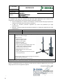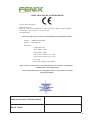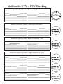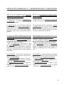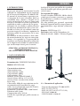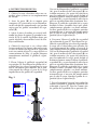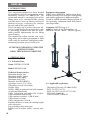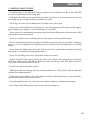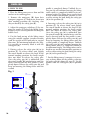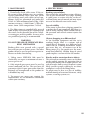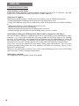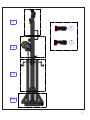
1
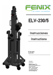
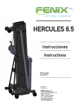
LIFTING TOWERS MEGARA 100 Instrucciones Instructions Nº de serie: Serial No.: Fabricante: Manufacturer: FENIX Stage, S.L. Avda. de los Trabajadores, 24 Horno de Alcedo 46026 - Valencia (Spain) Tel.: +34 96 125 08 55 [email protected] www.fenixstage.com C14.048G CERTIFICATE Page 1 of 1 Certificate date: 02-06-2014 Issued to: FENIX STAGE, S.L. Avda. de los Trabajadores, 24 46026 - Horno de Alcedo (Valencia) - Spain The Inspector that signs this certificate has done the report 6015.14G for the revision of the manufacturer documentation and machines design assessment, based on: Directive 2006/42/CE on machinery that establish “Essential health and safety requirements relating to the design and construction of machinery”. la BGV C1: “Accident prevention regulations for event and production for stage performances” BGG 912: “Testing of safety and mechanical equipment in staging and production for stage performances ". NAME: Lifting tower MARK: FENIX REFERENCE / TYPE / MODEL: Description: MEGARA 100 Lifting tower MEGARA 100 has been designed to vertically raise structures and lighting and sound equipment to different heights. Model properties: • Maximum height: 4,00 m. • Minimum height: 1,66 m. • Maximum load: 100kg. • Minimal load: 25kg. • Material: steel EN 10305-5 • Cable: galvanized steel EN12385-4. Max. load 6,39kN, strength quality 1770 N/mm2, diameter 3mm, composition 7x19+0 • Open base area: 1,57 x 1,57 m. • Area of the base closed: 0,36 x 0,36 m. • Weight: 33kg. • Winch: 450kg Maximum Load with automatic load retention brake Fixation of tower sections to working height with safety pins. Leg anchorage with safety pins. Bubble level to adjust tower vertical position. Each lifting tower has to be supplied with an EC declaration of conformity, including serial number and date of manufacturing. To comply with BGG 912, for some event or production, an inspection done by an expert could be required before start up. Based on reviewed documents, the inspector certifies that the machine COMPLIES with all minimal design dispositions of the regulations applied. In Bergondo at, June 2, 2014 Maite Fernández Varela Mines and Materials Engineer Expert in Industrial Safety 2 2 DECLARACION DE CONFORMIDAD La Dirección de la empresa: FENIX STAGE, S.L. Dirección: Avda. de los Trabajadores, 24 - Horno de Alcedo - 46026 - Valencia (España) Teléfono/fax: +34 96 125 08 55 / +34 96 125 13 05 CIF: B-91423046 Declaramos bajo nuestra exclusiva responsabilidad la conformidad del producto: Nombre: TORRE ELEVADORA Modelo: MEGARA 100 Descripción: Altura máxima: 4m. Altura mínima: 1,66m. Carga máxima: 100kg. Área de la base abierta: 1,57 x 1,57m. Área de la base cerrada: 0,36 x 0,36m. Peso: 33kg. Cabestrante: 450kg de carga máxima. al que se refiere esta declaración, con las disposiciones de la normativa de maquinaria CE 2006/42/EG y sus modificaciones. Persona facultada para elaborar el expediente técnico y representante autorizado: Mª Julia Niza del Río Número de serie / Serial number Fecha / Date 3 Verificación UVV / UVV Checking Verificación fábrica / Factory verification Partes comprobadas / Tested parts Conclusiones / Conclusions Firma / Signature Verificador / Verifier Fecha / Date Partes comprobadas / Tested parts Conclusiones / Conclusions Verificación experto (4º año) / Expert verification (4th year) Firma / Signature Verificador / Verifier Fecha / Date Partes comprobadas / Tested parts Conclusiones / Conclusions Verificación experto (1 por año) / Expert verification (1 x year) Fecha / Date Fecha / Date Conclusiones / Conclusions Partes comprobadas / Tested parts Firma / Signature Verificador / Verifier Partes comprobadas / Tested parts Fecha / Date Firma / Signature Verificador / Verifier Partes comprobadas / Tested parts Conclusiones / Conclusions Firma / Signature Verificador / Verifier Conclusiones / Conclusions 1 2 9 [BGV C1, BGG 912] 14 Primera verificación experto / First expert verification verificado en: verified on: 2 11 1 Firma / Signature Verificador / Verifier Fecha / Date 5 6 7 8 10 3 4 19 15 1 6 17 18 EXPLICACIÓN NORMA BGV C1 / EXPLANATION BGV C1 REGULATION BGV C1 es una normativa que regula los elementos de escenario y producción en la industria del entretenimiento. BGV C1 is a regulation for staging and production facilities for the entertainment and events’ industry. Adoptar dicha normativa es completamente voluntario, a excepción de Alemania donde es obligatorio. Adopting BGV C1 is completely voluntary, except in Germany where it is required. La aplicación de esta normativa sobre las torres elevadoras es muy recomendable debido a que en el sector del espectáculo y los eventos, las torres son usadas para desplazar cargas sobre artistas, personal técnico y público. The application of this regulation is highly recommended due to the fact that lifting towers in the entertainment and events’ industry are used to move loads over artists, technical staff and the audience. Las torres elevadoras FENIX que han sido certificadas de acuerdo a la BCV C1, aseguran al usuario: - Que han pasado estrictos controles durante su diseño, elección de materiales o verificaciones de carga y esfuerzo. - Que su verificación será llevada a cabo por expertos que comprobarán el estado del cable de acero y cabestrante, el funcionamiento de los pasadores de seguridad y el plegado / desplegado del sistema completo de perfiles. FENIX lifting towers that have been certified by BGV C1 ensure the customer: Desde FENIX, con el fin de conseguir un funcionamiento óptimo de las torres elevadoras recomendamos: - un uso responsable (ver punto 3, pág. 8) - seguir las instrucciones de uso (ver punto 4, pág. 9) - un manteniminto periódico (ver punto 5, pág. 10) - conocer los sistemas de prevención (ver punto 7, pág. 11). From FENIX, in order to obtain an optimal performance and the longest lifetime of the lifting towers, we strongly recommend: - a responsible use (see point 3, page 13) - to follow the how to use guidelines (see point 4, page 14) - a periodic maintenance (see point 5, page 15) - to know the preventions system (see point 7, page 16). - All the products undergo strict controls during their design, the choice of the materials or the load and effort verifications. - Their verification will be lead by experts that will test the status of the steel cable and winch, the operation of the safety pins and folding / unfolding of the entire profile system. 5 ÍNDICE 1.- INTRODUCCIÓN 7 2.- DATOS GENERALES 7 2.1.- Datos técnicos 7 2.2.- Normativa de aplicación 7 3.- NORMAS DE SEGURIDAD 8 4.- INSTRUCCIONES DE USO 9 5.- MANTENIMIENTO 10 6.- RIESGOS ESPECÍFICOS 10 7.- SISTEMAS DE PREVENCIÓN 11 INDEX 6 1.- INTRODUCTION 12 2.- GENERAL DATA 12 2.1.- Technical data 12 2.2.- Applicable regulations 12 3.- GENERAL SAFETY RULES 13 4.- HOW TO USE 14 5.- MAINTENANCE 15 6.- SPECIFIC RISKS 15 7.- PREVENTION SYSTEMS 16 ESPAÑOL 1. INTRODUCCIÓN El presente manual de instrucciones ha sido realizado en conformidad con los requisitos de la Directiva de Máquinas CE 2006/42/EG. El manual de instrucciones representa parte integrante de la torre elevadora, debe ser consultado antes, durante y después de la puesta en marcha de la torre así como cada vez que se considere necesario, respetando su contenido en todas y cada una de sus partes. Solamente de este modo se podrán alcanzar los objetivos fundamentales que se han establecido en la base de este manual como son prevenir riesgos de accidentes y optimizar lo máximo posible las prestaciones de la torre elevadora. En el marco de dicho manual se han cuidado minuciosamente los aspectos correspondientes a la seguridad y a la prevención de accidentes en el trabajo durante la utilización de la máquina destacando las informaciones que son de mayor interés para el usuario. Anclaje de las patas por gatillos de seguridad. Nivel de burbuja para ajustar posición vertical de la torre. Descripción del equipo: La torre elevadora MEGARA 100 ha sido diseñada para levantar estructuras y aparatos de iluminación y sonido en sentido vertical a diferentes alturas. Ha sido probada por personal capacitado habiendo superado todas las inspecciones de funcionamiento, carga máxima y dimensiones. Empresa: FENIX Stage, S.L. Dirección: Avda. de los Trabajadores, 24 Horno de Alcedo - 46026 - Valencia (España) ATENCIÓN: ANTES DE UTILIZAR LA TORRE ELEVADORA, LEA ATENTAMENTE ESTE MANUAL 2. DATOS GENERALES 2.1. Datos técnicos: Denominación: TORRE ELEVADORA Modelo: MEGARA 100 Características técnicas: Altura máxima: 4m. Altura mínima: 1,66m. Carga máxima: 100kg. Carga mínima: 25kg. Material: Acero según EN 10305-5. Área de la base abierta: 1,57 x 1,57m. Área de la base cerrada: 0,36 x 0,36m. Peso: 33kg. Cabestrante: 450kg de carga máxima con freno automático de retención de la carga. Cable: Acero galvanizado según EN 12385-4. Carga máxima cable: 652kg. Resistencia a la torsión cable: 1.960 N/mm². Diámetro cable: 3mm. Composición cable: 7x19+0. Sistema de seguridad por gatillo externo en tramos. 2.2.- Normativa de aplicación - Directiva de máquinas CE 2006/42/EG. - BGV C1 (GUV 6.175). - BGG 912 (GUV 66.15, GUV G-912). - EN 12385-4:2008-06. - DIN EN 10305-3:2010-05. 7 ESPAÑOL 3. NORMAS GENERALES DE SEGURIDAD - La torre elevadora es un elemento industrial diseñado para la elevación de cargas en sentido vertical, NUNCA se debe utilizar como plataforma elevadora de personas. - Colocar la torre elevadora sólo en superficies duras y planas, verificando que está en posición vertical. Nunca utilice cuñas ni elementos extraños para equilibrar la torre elevadora. - Comprobar que las patas están correctamente montadas y sujetas por sus pasadores retenedores de seguridad. - Nunca se debe elevar una carga sin antes verificar que está correctamente apoyada y centrada en los soportes elevadores adecuados, de forma que el peso de la carga sólo actúe en sentido vertical. - No se debe sobrepasar la capacidad de carga máxima indicada en la etiqueta de características de la torre elevadora y en este manual de instrucciones. - No usar escaleras encima de la torre elevadora ni apoyarlas en él para realizar ningún tipo de trabajo. - Tenga cuidado con todo tipo de salientes por encima de la torre elevadora como cornisas, balcones, letreros luminosos, etc. Es muy importante evitar la presencia de cables por debajo de la altura de trabajo de la torre elevadora. - Nunca se debe desplazar la torre elevadora si ésta se encuentra con la carga elevada. No es aconsejable realizar ningún tipo de movimiento, ni tan siquiera pequeños ajustes de posicionamiento. - Nunca utilizar la torre elevadora sobre ninguna superficie móvil o vehículo. - Antes de utilizar la torre elevadora, verificar el estado del cable, éste no debe presentar rotura de hilos o aplastamiento. No usar NUNCA cables defectuosos y en caso de duda cambie el cable. Sólo utilice cable de acero según describe este manual. - Fijar la manivela cuando la carga esté elevada. - La carga mínima para un funcionamiento del freno sin problemas es de 25kg. Sin esta carga mínima el freno no actuará. - No engrasar ni lubricar el mecanismo de freno del cabestrante. Los discos de freno, han sido engrasados con una grasa especial resistente al calor y la presión. No deben ser utilizados otros productos para evitar influir negativamente en el funcionamiento del freno. - Para el transporte de la torre elevadora hay que bajar todos los tramos. 8 ESPAÑOL 4. INSTRUCCIONES DE USO 1. Colocar la torre elevadora sobre una superficie plana y firme en su emplazamiento de trabajo. 2. Sacar las patas (H) de su soporte para transporte (C) e insertarlas en sus alojamientos de trabajo (G) comprobando que quedan sujetas por los gatillos retenedores de seguridad (K). 3. Ajuste la torre elevadora en vertical utilizando los platos de apoyo (J) girando la manivela (I) de la varilla reguladora hasta que quede nivelada, observando el nivel de burbuja estabilizador. 4. Colocar la carga que se va a elevar sobre la torre mediante un soporte adecuado según el caso, de forma que el peso de la carga sólo actúe en sentido vertical. La carga deberá ser como mínimo de 25kg. Se puede bloquear manualmente mediante el gatillo de seguridad (A). 5. Elevar: Liberar el gatillo de seguridad (A) en posición (T). Para liberar los gatillos de seguridad hay que elevar ligeramente la carga con el cabestrante para soltarlos. En la posición normal de trabajo, el peso de la carga impide liberar los gatillos de seguridad. Fig. 1 A Una vez desbloqueado el gatillo de seguridad (A), girar la manivela del cabestrante (B) en sentido contrario a las agujas del reloj hasta que descendiendo la carga, quede bajado al máximo el primer tramo. Liberar el gatillo de seguridad (A) y seguir bajando la torre hasta que éste segundo tramo baje al máximo. Desbloquear el gatillo de seguridad (A) y seguir bajando la torre elevadora hasta que quede completamente plegada a su altura mínima. La torre puede dejarse en cualquier posición intermedia que se necesite del mismo modo que al subir la carga, fijando el gatillo de seguridad (A) en la posición (S). 6. Descenso: Liberar el gatillo de seguridad (A) realizando el paso (T). Para liberar los gatillos de seguridad hay que elevar ligeramente la carga con el cabestrante para soltarlos. En la posición normal de trabajo, el peso de la carga impide liberar los gatillos de seguridad. Una vez desbloqueado el gatillo de seguridad (A), girar la manivela del cabestrante (B) en sentido contrario a las agujas del reloj hasta que descendiendo la carga, quede bajado al máximo el primer tramo. Liberar el gatillo de seguridad (A) y seguir bajando la torre hasta que éste segundo tramo baje al máximo. Desbloquear el gatillo de seguridad (A) y seguir bajando la torre elevadora hasta que quede completamente plegada a su altura mínima. La torre puede dejarse en cualquier posición intermedia que se necesite del mismo modo que al subir la carga, fijando el gatillo de seguridad (A) en la posición (S). 7. Para el transporte hay que bajar todos los tramos, liberando el gatillo de seguridad (A) realizando el paso (T). Fijar los tramos con los gatillos de seguridad (A) en posición (S). S T B J I H K G C 9 ESPAÑOL 5. MANTENIMIENTO 6. RIESGOS ESPECÍFICOS 1. Comprobar periódicamente el estado del cable. Si un cable presenta rotura de hilos o aplastamiento, debe ser sustituido inmediatamente por otro nuevo. No utilizar la torre elevadora con cables en mal estado. Utilizar solamente cable de acero galvanizado según EN 12385-4. Carga máxima cable: 652kg. Resistencia a la torsión cable: 1.960 N/mm². Diámetro cable: 3mm. Composicion cable: 7x19+0. 2. La torre elevadora se suministra completamente engrasada de fábrica. No obstante, se recomienda engrasar periódicamente según el uso, la corona dentada del cabestrante, la rosca de la manivela y los tramos. ATENCION: NO ENGRASAR NI LUBRICAR EL MECANISMO DEL FRENO Los discos de freno, han sido engrasados con una grasa especial resistente al calor y la presión. No deben ser utilizados otros productos para evitar influir negativamente en el funcionamiento del freno. No es necesario engrasar los discos de freno. 3. La torre elevadora MEGARA 100 debe ser comprobada por un experto como mínimo una vez al año de acuerdo con su utilización. 4. Solamente deben utilizarse piezas de repuesto originales para garantizar una continuada seguridad de uso. El usuario pierde todos los derechos de garantía, si incorpora otros repuestos que no sean originales o lleva a cabo cualquier modificación en el producto. 5. Para solicitar cualquier repuesto, contacte con el fabricante o con un distribuidor autorizado dentro de su territorio. Fallo del sistema de freno Puede producirse por deficiencias en el sistema de frenado o por una mala instalación. Si deja de funcionar puede provocar un riesgo importante de pérdida de control de la mercancía elevada y originar golpes y/o contusiones sobre los usuarios o golpes sobre los materiales que se encuentren próximos a la torre. 10 Pérdida de estabilidad Si se coloca la torre sobre un terreno inclinado o sobre una superficie que no sea completamente lisa existe el riesgo de pérdida de estabilidad lo que daría lugar generalmente a un vuelco de 90º con riesgo de lesiones graves para los operarios. Caída de objetos a distinto nivel Como elemento de elevación, su trabajo en altura hace que haya un riesgo importante de caída a diferente nivel de los objetos elevados, bien por fallo de los mecanismos de sujeción, desgaste de piezas, suciedad, etc. bien por utilización incorrecta de la torre (Ej: para elementos por encima de la carga máxima permitida). El descenso brusco del material elevado supone un elevado riesgo para el operario. Golpes y/o contusiones por objetos Este riesgo tan sólo en contadas ocasiones se traduce en accidente para el operario que conduce la operación, dada su situación durante el proceso de elevación; el riesgo de golpes por el elemento sobreelevado puede más bien afectar a personas que deambulen o tengan su puesto de trabajo en zonas cercanas a la torre elevadora. Su origen puede ser debido a pérdida de estabilidad, mal funcionamiento de elementos estructurales, mal funcionamiento de sistemas de seguridad, sistemas de sujeción, etc. ESPAÑOL 7. SISTEMAS DE PREVENCIÓN Sobre fallo del sistema de freno Disponer de cabestrante conforme a las normas mencionadas en la directiva de seguridad BGV C1, especialmente DIN EN ISO 12100:2011-03 y DIN EN ISO 12100-1:2004-04. Sobre pérdida de estabilidad El mantenimiento de la estabilidad de la torre elevadora debe realizarse básicamente con las siguientes medidas: • Profesionalización, adiestramiento, formación y concienciación del riesgo a los usuarios de las torres. • Dotación de diferentes dispositivos de seguridad y consejos por parte del fabricante, para reforzar su estabilidad como por ejemplo: - Pasadores de seguridad que fijan la torre una vez elevada. - Nivel de burbuja para facilitar el ajuste vertical. - Marcado de la carga máxima que puede elevar la torre. - Especificación de la pendiente máxima a la que pueden acceder las torres de forma segura. Sobre caída de objetos a distinto nivel, golpes y/o contusiones con objetos El riesgo de caída de objetos a distinto nivel puede prevenirse con la utilización de elementos de seguridad homologados, por ejemplo, un gatillo de seguridad que fije el tramo interior de la torre en su posición de trabajo, de forma que el cable no soporta la carga y se garantiza la imposibilidad de una caída. En caso de rotura de cable, actúa el freno automáticamente. Por otra parte, si los elementos de acero están zincados se protege el conjunto de la oxidación y la corrosión. También se pueden minimizar estos riesgos con un adecuado mantenimiento de la torre elevadora. El usuario deberá hacer inspecciones periódicas de los elementos de seguridad y realizar las reparaciones necesarias en caso de detectar deficiencias. Asimismo, se pueden reducir las consecuencias de estos riesgos limitando la zona de acceso a la torre elevadora y con adecuada formación del personal. Otras consideraciones Este equipo no emite más de 80 dB. 11 ENGLISH 1. INTRODUCTION This instruction manual has been drafted in accordance with the requirements of the Machinery Directive CE 2006/42/EG. The instruction manual is an integral part of the lifting tower to be consulted before, during and after tower’s start-up, likewise whenever deemed necessary, respecting the contents for each and all the parts thereof. This is the only way to achieve the basic objectives established in the manual’s base such as preventing accident risks and the maximum possible optimisation for the lifting tower features. This manual has taken extreme care regarding safety and accident prevention at work while using the machine, highlighting information of particular interest to the user. Equipment description: Lifting tower MEGARA 100 has been designed to vertically raise structures and lighting and sound equipment to different heights. Tested by skilled personnel having passed all the operating, maximum load and dimension inspections. Company: FENIX Stage, S.L. Address: Avda. de los Trabajadores, 24 Horno de Alcedo - 46026 - Valencia (Spain) ATTENTION: BEFORE TO USING THE LIFTING TOWER, READ THIS MANUAL CAREFULLY 2. GENERAL DATA 2.1. Technical Data: Name: LIFTING TOWER Model: MEGARA 100 Technical characteristics: Maximum height: 4m. Minimum height: 1,66m. Maximum load: 100kg. Minimum load: 25kg. Material: Steel EN 10305-5. Open base area: 1,57 x 1,57m. Closed base area: 0,36 x 0,36m. Weight: 33kg. Winch: 450kg maximum load with automatic load retention brake. Cable: Galvanized steel under EN 12385-4. Cable maximum load: 652kg. Cable torsion resistance: 1.960 N/mm². Cable diameter: 3mm. Cable composition: 7x19+0. Fixation of tower sections to working height with safety pins. Leg anchorage with safety pins. Bubble level to adjust tower’s vertical position. 12 2.2. Applicable regulations - Machinery Directive CE 2006/42/EG. - BGV C1 (GUV 6.175). - BGG 912 (GUV 66.15, GUV G-912). - EN 12385-4:2008-06. - DIN EN 10305-3:2010-05. ENGLISH 3. GENERAL SAFETY RULES - The lifting tower is an industrial element designed to raise loads vertically, it must NEVER be used as a platform elevator for people. - Only place the lifting tower on firm flat grounds checking it is in vertical position. Do not use wedges or any strange elements to balance the hoist. - Check legs are correctly assembled and secured by their safety pins. - Never raise a load without first checking it is correctly supported and centred on the appropriate lifting tower supports, so the load only acts vertically. - Never surpass the maximum load capacity indicated on the lifting tower characteristics label and on this instruction manual. - Never use a ladder over the lifting tower or lean against it for any kind of work. - Beware of any kind of projection above the lifting tower like cornices, balconies, luminous signs, etc. It is very important to avoid the presence of cables below the lifting tower’s working height. - Never move the lifting tower when the load is raised. It is inadvisable to make any kind of movement, even small positioning adjustments. - Never use the lifting tower over any mobile surface or vehicle. - Before using the lifting tower, check the cable’s state, which must not present any broken threads or compression. NEVER use defective cables and change cable if in doubt. Only use steel cable as described on this manual. - Fix the lever when the load is raised. - Minimum load for braking function without problems is 25kg. Brake will not function without this minimum load. - Neither grease nor lubricate the winch brake mechanism. Braking disks were greased with a special heat and pressure resistant grease. - No other products must be used to prevent negative influence on brake functioning. - All sections of the lifting tower must be lowered to transport it. 13 ENGLISH 4. HOW TO USE 1. Place the lifting tower over a firm and flat surface on its working place. 2. Remove the outriggers (H) from their transport supports (C) and insert them into their working positions (G) checking that they are fixed by the safety pins (K). 3. Adjust the outrigger stabilisers (J) by turning the cranks (I) to level the lifting tower. Ensure it is in a vertical position checking the bubble level. 4. Put the load on top of the lifting tower using the suitable support, in order to make work the weight of the load only in vertical direction. The minimum load must be 25kg. It is possible to manually block it with the safety pins (A). 5. Raising: release the safety pins (A) in its position (T). To release them, turn slightly the winch handle to elevate the load. In the normal working position, the load’s weight does not allow to release the safety pins. Once the safety pin (A) is unblocked, turn the winch handle (B) anticlockwise until the load is lowered and the first profile is completely down. Release the safety pins (A) and keep on lowering the lifting tower until the second Fig. 1 A S T B J I H K G 14 C profile is completely down. Unblock the safety pin (A) and continue lowering the lifting tower until it is completely folded at its minimum height. The lifting tower can be fixed in any needed intermediate position as well as when raising the load, fixing the safety pin (A) in the position (S). 6. Lowering: release the safety pins (A) in its position (T). To release them, turn slightly the winch handle to elevate the load. In the normal working position, the load’s weight does not allow to release the safety pins. Once the safety pin (A) is unblocked, turn the winch handle (B) anticlockwise until the load is lowered and the first profile is completely down. Release the safety pins (A) and keep on lowering the lifting tower until the second profile is completely down. Unblock the safety pin (A) and continue lowering the lifting tower until it is completely folded at its minimum height. The lifting tower can be fixed in any needed intermediate position as well as when raising the load, fixing the safety pin (A) in the position (S). 7. For the lifting towers’ transport it is necessary to bring down all the profiles, releasing the safety pin (A) doing the step (T). Fix the profiles with the safety pins (A) in position (S). ENGLISH 5. MAINTENANCE 6. SPECIFIC RISKS 1. Periodically check cable status. If the cable seems to have broken wires or crushing, replace immediately with a new one. Never use the lifting tower with cables in bad conditions. Only use galvanized steel under EN 12385-4. Cable maximum load: 652kg. Cable torsion resistance: 1.960 N/mm². Cable diameter: 3mm. Cable composition: 7x19+0. Braking system failure May occur due to braking system deficiencies or bad installation. If it stops working it could cause a serious risk due to the raised load being out of control and may injure users or hit materials next to the tower. 2. The lifting tower is supplied fully greased from factory. Nevertheless, the crown gear of the winch, to the threaded bar of the stabiliser outriggers and the profiles, because of its use periodical greasing is recommended. WARNING: DO NOT GREASE OR LUBRICATE BRAKING MECHANISM Braking disks were greased with a special heat and pressure resistant grease. No other product must be used to prevent negative influence on brake functioning. 3. Lifting tower MEGARA 100, must be checked by an expert a minimum of once a year as per its use. 4. Only original spare parts must be used to ensure continued safe use. The user loses all guarantee rights if spare parts other than the originals are incorporated or the product in is modified any way. 5. To request any spare part, contact the manufacturer or an authorised distributor within your territory. Loss of stability If the tower is placed on a sloping ground or a surface that is not completely flat, there is a risk of losing stability which would lead to a 90º overturn with risk of serious injuries for workers. Objects dropping to a different level As an elevation equipment and due to its working height, there is a serious risk of raised objects dropping to a different level, either due to securing mechanism failure, part wear, dirt, etc., or incorrect use of the lifting tower (E.g.: for goods over the maximum load allowed). Sudden drop of raised goods implies a serious risk for the worker. Knocks and/or contusions due to objects This risk only occasionally causes an accident to the worker running the operation due to his location during the elevation process; the risk of knocks from a raised element is more likely to affect people walking by or whose workplace is next to the lifting tower. Its origin may be due to a loss of stability, malfunctioning of structural elements, safety systems, securing systems, etc. 15 ENGLISH 7. PREVENTION SYSTEMS About braking system failure Equip with winch complying with regulations metioned in the BGV C1 directive, specially DIN EN ISO 12100:2011-03 and DIN EN ISO 12100-1:2004-04. About loss of stability Maintenance of lifting tower stability must basically be as per the following measures: • Professionalization, training and risk awareness of lifting tower users. • Equip with different safety devices and advices from the manufacturer to reinforce stability, as: - Safety pins which secure the lifting tower once raised. - Bubble level to help vertical adjustment. - Maximum load specification that the lifting tower can raise. - Maximum slope specification which the lifting tower can access safely. About objects falling to a different level, knocks and/or contusions with objects The risk of objects falling to a different level can be prevented by using homologated safety elements, e.g., a safety pin which fixes the inner profile of the lifting tower in its working position, so the cable does not support load and guaranteeing the impossibility of a drop. In the event of cable breakage, the braking system will act automatically. Furthermore, if steel elements have been zinc coated it protects the entire unit from oxidation and corrosion. These risks can also be minimised with correct lifting tower maintenance. The user must perform periodical inspections on safety elements and make the necessary repairs in case deficiencies are detected. Moreover, the consequences of these risks can be reduced limiting an access area to the lifting tower and with a correct training of personnel. About noise emissions This equipment doesn’t produce more than 80 dB. 16 T1 S T2 T T3 T4 17 1078 T1 3045 2262 3415 3416 P/40 3417 4008 P/40 P/40 1017 3015 1308 1046 1083 x2 2013 2225 2224 3085 1821 4007 3414 1817 18 1825 2026 2226 T2 3014 3055 1035 1308 3101 1404x3 1025x3 1403 T3 1028 3043 1305 1302 1305 1004 2050 3063 2265 3042 1010 19 T4 S1 3072 1306 1030 S1 2025 3016 1003 1002 20 3024 1003 x2 Ref. - 1002 1003 1004 1010 1017 1025 1028 1030 1035 1046 1078 1083 1302 1305 1306 1308 1401 1403 1404 1821 1825 2013 2025 2026 2050 2224 2225 2226 2262 2265 3014 3015 3016 3024 3042 3043 3045 3055 3063 3072 3085 3101 3414 3415 3416 3417 4007 4008 Descripción Tornillo cónico Tornillo cónico Tornillo hexagonal Tornillo cónico Tornillo allen Tornillo allen Tornillo hexagonal Tornillo hexagonal Tornillo allen Tornillo allen Tornillo palometa Tornillo allen Tuerca Tuerca Tuerca Tuerca Arandela Arandela Arandela Anilla de llavero Nivel burbuja Portapoleas Pletina Pletina Maneta Mastil Barra Barra Contera Pata Polea Polea Polea Eje Plato poliamida Pomo baquelita pequeño Gatillo seguridad completo Cable Varilla roscada Rueda Gatillo anilla completo Cabestrante Eje gatillo Base gatillo Eje gatillo Pomo gatillo Muelle gatillo Muelle gatillo - MEGARA 100 Conical screw Conical screw Hexagonal screw Conical screw Allen screw Allen screw Hexagonal screw Hexagonal screw Allen screw Allen screw Butterfly screw Allen screw Nut Nut Nut Nut Washer Washer Washer Keychain ring Bubble level Pulley-holder Plate Plate Hand crank Mast Bar Bar Chape Leg Pulley Pulley Pulley Axis Polyamide plate Hand crank small Complete safetypin Cable Threaded bar Wheel Complete ring pin Winch Pin axis Pin base Pin axis Pin knob Pin spring Pin spring Fenix Stage Description 21 LIFTING TOWERS NOTAS / NOTES 22 LIFTING TOWERS NOTAS / NOTES 23 FENIX Stage, S.L. Avda. de los Trabajadores, 24 Horno de Alcedo 46026 - Valencia (Spain) Tel.: +34 96 125 08 55 [email protected] www.fenixstage.com