1
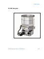
TV 1001 Navigator
Pump models: 969-8931, 969,-8932,
969-8934, 969-8946, 969-8933, 969-8947
Kit models: 969-8838, 969-8839, 969-8841,
969-8844, 969-8840, 969-8845
Controller models: 969-8978
Manual de Instrucciones
User Manual
87-900-945-01 (I)
04/2011
Notices
© Agilent Technologies, Inc. 2011
No part of this manual may be
reproduced in any form or by any
means (including electronic storage
and retrieval or translation into a
foreign language) without prior
agreement and written consent from
Agilent Technologies, Inc. as governed
by United States and international
copyright laws.
Manual Part Number
Publication Number: 87-900-945-01 (I)
Edition
Edition 04/2011
Printed in ITALY
Agilent Technologies Italia S.p.A.
Vacuum Products Division
Warranty
The material contained in this
document is provided “as is,” and is
subject to being changed, without
notice, in future editions. Further, to
the maximum extent permitted by
applicable law, Agilent disclaims all
warranties, either express or implied,
with regard to this manual and any
information contained herein,
including but not limited to the
implied warranties of merchantability
and fitness for a particular purpose.
Agilent shall not be liable for errors
or for incidental or consequential
damages in connection with the
furnishing, use, or performance of
this document or of any information
contained herein. Should Agilent and
the user have a separate written
agreement with warranty terms
covering the material in this
document that conflict with these
terms, the warranty terms in the
separate agreement shall control.
Via F.lli Varian, 54
10040 Leinì (TO)
ITALY
Technology Licenses
The hardware and/or software
described in this document are
furnished under a license and may be
used or copied only in accordance
with the terms of such license.
contract clause. Use, duplication or
disclosure of Software is subject to
Agilent Technologies’ standard
commercial license terms, and nonDOD Departments and Agencies of the
U.S. Government will receive no
greater than Restricted Rights as
defined in FAR 52.227-19(c)(1-2) (June
1987). U.S. Government users will
receive no greater than Limited Rights
as defined in FAR 52.227-14 (June
1987) or DFAR 252.227-7015 (b)(2)
(November 1995), as applicable in any
technical data.
Trademarks
Windows and MS Windows are U.S.
registered trademarks of Microsoft
Corporation.
Safety Notices
CAUTION
A CAUTION notice denotes a hazard.
It calls attention to an operating
procedure, practice, or the like that, if
not correctly performed or adhered to,
could result in damage to the product
or loss of important data. Do not
proceed beyond a CAUTION notice
until the indicated conditions are fully
understood and met.
Restricted Rights Legend
If software is for use in the
performance of a U.S. Government
prime contract or subcontract,
Software is delivered and licensed as
“Commercial computer software” as
defined in DFAR 252.227-7014 (June
1995), or as a “commercial item” as
defined in FAR 2.101(a) or as
“Restricted computer software” as
defined in FAR 52.227-19 (June 1987)
or any equivalent agency regulation or
WARNING
A WARNING notice denotes a
hazard. It calls attention to an
operating procedure, practice, or the
like that, if not correctly performed
or adhered to, could result in
personal injury or death. Do not
proceed beyond a WARNING notice
until the indicated conditions are
fully understood and met.
TV 1001 Navigator User Manual / 87-900-945-01 (I)
TV 1001 Navigator
TV 1001 Navigator
TV 1001 Navigator User Manual / 87-900-945-01 (I)
3/312
TV 1001 Navigator
4/312
TV 1001 Navigator User Manual / 87-900-945-01 (I)
Contents
Contents
1
Istruzioni per l’uso 15
Indicazioni di Sicurezza per Pompe Turbomolecolari
Informazioni Generali
16
17
Immagazzinamento 19
Preparazione per l’installazione 20
Installazione
21
Fissaggio della pompa
Uso
22
24
Manutenzione 27
Smaltimento
2
28
Gebrauchsanleitung 29
Sicherheitshinweise für Turbomolekularpumpen 30
Allgemeine Informationen
Lagerung
31
33
Vor der Installation 34
Installation 35
Befestigung der Pumpe 36
Gebrauch
38
Wartung
41
TV 1001 Navigator User Manual / 87-900-945-01 (I)
5/312
Contents
Entsorgung 42
3
Mode d’emploi
43
Normes de sécurité pour Pompe Turbomoléculaires
Indications générales
Stockage
44
45
47
Preparation pour l’installation
48
Installation 49
Fixation de la pompe 50
Utilisation 52
Entretien
55
Mise au rebut
4
56
Manual de istrucciones 57
Indicaciones de Seguridad para Bombas Turbomoleculares
58
Información general 59
Almacenamiento
61
Preparación para la instalación
62
Instalación 63
Fijación de la bomba 64
Uso
66
Mantenimiento 69
Eliminación 70
6/312
TV 1001 Navigator User Manual / 87-900-945-01 (I)
Contents
5
Manual de Istruções
71
Indicações de Segurança para Bombas Turbomoleculares 72
Informações gerais 73
Armazenagem 75
Preparação para a instalação 76
Instalação 77
Fixação da bomba
Utilização
78
80
Manutenção
83
Eliminação 84
6
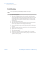
Bedrijfshandleiding 85
Veiligheidsinstructies voor Turbomoleculaire pompen 86
Algemene informatie
Opslag
89
Uitpakken
90
Installatie
91
87
Bevestiging van de pomp
Gebruik
92
94
Onderhoud 97
Afvalverwerking 98
7
Istruktionsbog
99
Sikkerhedsanvisninger for Molekylære turbopumper
TV 1001 Navigator User Manual / 87-900-945-01 (I)
100
7/312
Contents
Generel information 101
Opbevaring 103
Forberedelser før installation 104
Installation 105
Fastgørelse af pumpe
106
Anvendelse 108
Nødstop
110
Vedligeholdelse 111
Bortskaffelse
8
112
Bruksanvisning
113
Säkerhetsanvisningar för Molekylära turbopumpar 114
Allmän information 115
Förvaring
117
Förberedelser för installation 118
Installation 119
Fastsättning av pump
120
Användning 122
Underhåll
125
Bortskaffning
9
126
Instruksjon Manual 127
Sikkerhetsanvisninger for Turbomolekylære pumper
128
Generell informasjon 129
8/312
TV 1001 Navigator User Manual / 87-900-945-01 (I)
Contents
Lagring
131
Klargjøre til installasjon 132
Installasjon 133
Festing av pumpen 134
Bruk
136
Vedlikehold 139
Eliminering 140
10 Ohjekäsikirja
141
Turbomolekyylipumppujen Turvaohjeet
Yleisiä tietoja
142
143
Varastointi 145
Valmistelut asennusta varten146
Asennus
147
Pumpun kinnitys148
Käyttö
150
Huolto
153
Hävittäminen
154
11 Felhasználói Kézikönyv 155
Biztonsági útmutató Turbómolekuláris szivattyúkhoz 156
Általános informáicó 157
Tárolás
159
Elkészítés telepítésre
160
TV 1001 Navigator User Manual / 87-900-945-01 (I)
9/312
Contents
Telepítés
161
A szivattyú rögzítése 162
Használat
164
Karbantartás
167
Megsemmisítés 168
12 Podrecznik Instrukcji
169
Wskazówki dotyczce bezpieczestwa dla Pomp Turbomolekularnych
170
Informacje ogolne
171
Magazynowanie 173
Przygotowanie do instalacji 174
Instalacja
175
Mocowanie pompy 176
Uytkowanie
178
Konserwacja
181
Przetworstwo odpadow 182
13 Návod k Použití
183
Bezpenostní návod pro Turbomolekulární vývvy 184
Všeobecné informace
185
Uskladnní 187
Píprava k instalaci 188
Instalace
189
Montáž vývvy 190
10/312
TV 1001 Navigator User Manual / 87-900-945-01 (I)
Contents
Použití
192
Údržba
195
Likvidace
196
14 Návod na Obsluhu 197
Bezpenostné pokyny pre Turbomolekulárne vývevy
Všeobecné informácie
Uchovávanie
199
201
Príprava na inštaláciu
Inštalácia
198
202
203
Upevnenie vývevy
Použitie
206
Údržba
209
Likvidácia
210
204
15 Prironik za Navodila
211
Varnostna navodila za Turbomolekularne rpalke 212
Splošne informacije 213
Shranjevanje
215
Priprava za montažo 216
Montaža
217
Pritrjevanje rpalke 218
Uporaba
220
Vzdrževanje 223
TV 1001 Navigator User Manual / 87-900-945-01 (I)
11/312
Contents
Odlaganje opadkov 224
16 Instructions for Use 225
Safety Guideline for Turbomolecular Pumps
226
General Information 227
Storage
229
Preparation for installation
230
Installation 231
Pump fixing 232
Use
234
Maintenance
Disposal
237
238
17 Technical Information
239
Description of the TV 1001 Navigator 241
Technical Specification 248
TV 1001 Navigator Outline
Interconnections
250
254
RS 232/RS 485 Communication Description 266
Inlet Screen Installation 275
Heater Band Installation 278
Air Cooling Kit Installation
280
Water Cooling Kit Installation
Vent Accessories
12/312
284
287
TV 1001 Navigator User Manual / 87-900-945-01 (I)
Contents
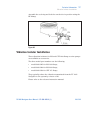
Vibration Isolator Installation 291
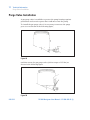
Purge Valve Installation 292
Serial Cable Installation 293
TV 1001 Controller Installation
294
Pump Used with Corrosive Gases 302
Pump Used in Presence of Magnetic Fields
304
Accessories and Spare Parts 305
TV 1001 Navigator User Manual / 87-900-945-01 (I)
13/312
Contents
14/312
TV 1001 Navigator User Manual / 87-900-945-01 (I)
TV 1001 Navigator User Manual
4
Manual de istrucciones
Indicaciones de Seguridad para Bombas Turbomoleculares
58
Información general 58
Almacenamiento
61
Preparación para la instalación 62
Instalación
63
Fijación de la bomba 64
Uso66
Encendido y Uso del TV 1001 Navigator 67
Parada del TV 1001 Navigator
68
Parada de Emergencia 68
Mantenimiento 69
Eliminación
70
Traducción de las instrucciones originales
57/312
4
Manual de istrucciones
Indicaciones de Seguridad para Bombas Turbomoleculares
Indicaciones de Seguridad para Bombas
Turbomoleculares
Las bombas Turbomoleculares descritas en el siguiente manual de
instrucciones tienen una elevada cantidad de energía cinética debido
a la alta velocidad de rotación en combinación a la masa específica
de sus rotores.
En el caso de un daño del sistema, por ejemplo por un contacto entre
el rotor y el estator o por una rotura del rotor, la energía de rotación
podría ser liberada.
¡ADVERTENCIA!
58/312
Para evitar daños a los equipos y prevenir lesiones a los operadores, es
necesario seguir atentamente las instrucciones de instalación descritas
en el presente manual!
TV 1001 Navigator User Manual / 87-900-945-01 (I)
Manual de istrucciones
Información general
4
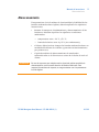
Información general
Este equipo es para uso profesional. El usuario ha de leer
atentamente el presente manual de instrucciones y cualquier otra
información suplementaria facilitada por Agilent antes de usar el
aparato. Agilent se considera libre de posibles responsabilidades
debidas al incumplimiento total o parcial de las instrucciones, al uso
impropio por parte de personal no preparado, a operaciones no
autorizadas o a un uso contrario a las normas nacionales específicas.
El TV 1001 Navigator es un sistema integrado compuesto por una
bomba turbomolecular para aplicaciones de alto y ultra alto vacío
integrada por el controler correspondiente. El sistema puede
bombear cualquier tipo de gas o de composición gaseosa, pero no es
adecuado para bombear líquidos o partículas sólidas. El efecto de
bombeo se obtiene mediante una turbina rotativa de alta velocidad
(38000 r.p.m. máx.) movida por un motor eléctrico trifásico de alto
rendimiento. El TV 1001 Navigator no posee ningún agente
contaminante y por lo tanto es adecuado para aplicaciones que
requieren un vacío’ “limpio”.
Asimismo, el TV 1001 Navigator posee conectores auxiliares con los
que se puede alimentar un ventilador adicional, accionar la válvula
de ventilación, pilotarla a distancia con un ordenador host conectado
mediante línea serial (RS 232/RS 485).
A continuación se facilita toda la información necesaria para
garantizar la seguridad del operador al usar el aparato. En el anexo
“Technical Information” se facilita información más detallada.
TV 1001 Navigator User Manual / 87-900-945-01 (I)
59/312
4
Manual de istrucciones
Información general
Este manual utiliza las convenciones siguientes:
¡ATENCIÓN!
Los mensajes de atención se visualizan antes de los procedimientos que, al
no respetarse, podrían provocar daños al equipo.
¡ADVERTENCIA! Los mensajes de advertencia atraen la atención del operador sobre un
procedimiento o una operación específica que, al no realizarse
correctamente, podría provocar graves lesiones personales.
NOTA
60/312
Las notas contienen información importante extraída del texto.
TV 1001 Navigator User Manual / 87-900-945-01 (I)
Manual de istrucciones
Almacenamiento
4
Almacenamiento
Para garantizar el nivel máximo de funcionalidad y fiabilidad de las
bombas turbomoleculares Agilent, deberán aplicarse las siguientes
instrucciones:
¡ATENCIÓN!
durante el transporte, desplazamiento y almacenamiento de las
bombas no deberán superarse las siguientes condiciones
ambientales:
temperatura: entre –20 °C y 70 °C;
humedad relativa: entre 0 y 95 % (no condensante);
el cliente deberá activar siempre las bombas turbomoleculares en
modalidad Soft-Start al recibirlas y ponerlas en funcionamiento
por primera vez;
el período máximo de almacenamiento de una bomba
turbomolecular es de diez meses a contar de la fecha de envío al
cliente.
En caso de superarse por cualquier motivo el período máximo permitido de
almacenamiento, será necesario devolver la bomba al fabricante. Para
mayores informaciones al respecto, se ruega contactar con el representante
local de Agilent.
TV 1001 Navigator User Manual / 87-900-945-01 (I)
61/312
4
Manual de istrucciones
Preparación para la instalación
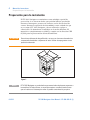
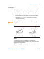
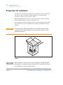
Preparación para la instalación
El TV 1001 Navigator se suministra en un embalaje especial de
protección; si se observan daños, que podrían haberse producido
durante el transporte, ponerse en contacto con la oficina local de
ventas. Durante la operación de desembalaje, tener cuidado de que
no se caiga el TV 1001 Navigator y de no someterlo a golpes o
vibraciones. No abandonar el embalaje en el medio ambiente. El
material es completamente reciclable y cumple con la directiva CEE
85/399 para la preservación del medio ambiente.
¡ATENCIÓN!
Para evitar problemas de desgasificación, no tocar con las manos desnudas los
componentes destinados a exponerse al vacío. Utilizar siempre guantes u otra
protección adecuada.
Figura 1
NOTA
62/312
El TV 1001 Navigator no puede dañarse permaneciendo simplemente expuesto a
la atmósfera. De todas formas, se aconseja mantener cerrada la bomba hasta
que se instale en el sistema para evitar su posible contaminación por polvo.
TV 1001 Navigator User Manual / 87-900-945-01 (I)
Manual de istrucciones
Instalación
4
Instalación
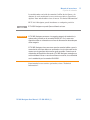
No instalar ni/o utilizar la bomba en lugares expuestos a agentes
atmosféricos (lluvia, hielo y nieve), polvo y gases agresivos, en
lugares explosivos o con alto riesgo de incendio. Durante el
funcionamiento es necesario que se respeten las condiciones
ambientales siguientes:
¡ATENCIÓN!
presión máxima: 2 bares por encima de la presión atmosférica
temperatura: de +5 °C a +35 °C (véase gráfico en el anexo
“Technical Information”)
humedad relativa: 0 – 95 % (no condensadora).
Despegar el adhesivo y quitar el tapón de protección sólo al conectar la
bomba al sistema.
Figura 2
Cuando existan campos electromagnéticos, la bomba ha de
protegerse mediante pantallas oportunas. Véase el anexo “Technical
Information” para más detalles.
El TV 1001 Navigator ha de conectarse a una bomba primaria (véase
diagrama en “Technical Information”).
TV 1001 Navigator User Manual / 87-900-945-01 (I)
63/312
4
Manual de istrucciones
Fijación de la bomba
Fijación de la bomba
¡ADVERTENCIA! En caso de dañarse el rotor, la conexión entre la bomba y el sistema
puede ser sometida a un par de fuerza excesivo. En estas circunstancias,
la conexión podría no resistir a dicho par de fuerza y, como
consecuencia, la bomba podría separarse del sistema o el motor podría
separarse respecto del contenedor de la bomba. En este caso fragmentos
de metal pueden ser proyectados por la bomba o por el sistema, con
consiguiente grave riesgo de lesiones o muerte y/o daños a los aparatos
adyacentes.
Fijar el TV 1001 Navigator en posición estable, montando la brida de
entrada de la turbo-bomba en la contrabrida del sistema, con
conexión capaz de resistir a un par de 8900 Nm en torno a su propio
eje. A modo de ejemplo, la brida ISO-K puede fijarse con mordazas de
acero de alta resistencia (como el modelo Agilent IC 63250 DCMZ).
En la siguiente tabla se indican, respecto de cada brida, la cantidad
de mordazas IC 63250 DCMZ necesarias y el par de apriete con el
cual fijarlas.
Tab. 1
Brida
N.
Par de apriete
ISO 160
10
35 Nm
ISO 200
8
35 Nm
ISO 250
6
35 Nm
En la siguiente tabla se indican, respecto de cada brida ISO-F, la
cantidad de los tornillos necesarios y el par de apriete con el cual
fijarlas.
Tab. 2
Brida
N.
Par de apriete
ISO 200 F
12
5 Nm
ISO 250 F
12
5 Nm
En el caso de las bridas F los tornillos de acero deben ser de clase > 8.8
64/312
TV 1001 Navigator User Manual / 87-900-945-01 (I)
Manual de istrucciones
Fijación de la bomba
4
La turbobomba con brida de entrada ConFlat ha de fijarse a la
cámara de vacío mediante los accesorios mecánicos específicos
Agilent. Para más detalles véase el anexo “Technical Information”.
El TV 1001 Navigator puede instalarse en cualquier posición.
NOTA
¡ATENCIÓN!
El TV 1001 Navigator no puede fijarse utilizando su base.
El TV 1001 Navigator pertenece a la segunda categoría de instalación (o
sobretensión) prevista por la normativa EN 61010-1. Por lo tanto este
dispositivo debe ser conectado a una línea de alimentación adecuada para
dicha categoría.
El TV 1001 Navigator tiene conectores para las entradas/salidas y para la
comunicación serial que deben ser conectados a los circuitos externos de
manera que ninguna parte bajo tensión quede accesible. Controlar que el
aislamiento del dispositivo conectado al TV 1001 Navigator mantenga una
acción aisladora incluso en caso de verificarse una avería, de conformidad
con lo establecido por la normativa EN 61010-1.
Para instalar los accesorios opcionales, véase “Technical
Information”.
TV 1001 Navigator User Manual / 87-900-945-01 (I)
65/312
4
Manual de istrucciones
Uso
Uso
En este apartado se citan los procedimientos operativos principales.
Antes de usar el sistema realizar todas las conexiones eléctricas y
neumáticas. Durante el posible calentamiento de la cámara de vacío,
la temperatura de la brida de entrada no ha de ser superior a 120 °C.
¡ADVERTENCIA! No hacer funcionar nunca la bomba si la brida de entrada no está
conectada al sistema o no está cerrada con la brida de cierre. No tocar la
turbo-bomba y sus posibles accesorios durante las operaciones de
calentamiento. La alta temperatura puede provocar lesiones a las
personas.
¡ATENCIÓN!
Evítense golpes, oscilaciones o bruscos desplazamientos de la turbobomba
durante su funcionamiento. Los cojinetes podrían dañarse. Para el envío de
aire de la bomba utilizar aire o gas inerte sin polvo o partículas. La presión de
entrada a través de la puerta deberá ser inferior a 2 bar (por encima de la
presión atmosférica). Para bombear gases agresivos estas bombas están
dotadas de una puerta específica mediante la cual es necesario suministrar a
la bomba un caudal de gas inerte (Nitrógeno o Argón) para proteger los
rodamientos (véase el anexo “Technical Information”).
¡ADVERTENCIA! Cuando la bomba se utiliza para bombear gases tóxicos, inflamables o
radioactivos, seguir los procedimientos apropiados típicos de cada gas.
No usar la bomba cuando haya gases explosivos.
66/312
TV 1001 Navigator User Manual / 87-900-945-01 (I)
Manual de istrucciones
Uso
4
Encendido y Uso del TV 1001 Navigator
Para encender el TV 1001 Navigator basta con suministrar la tensión
de alimentación. El controlador incorporado reconoce
automáticamente la presencia de las señales de interbloqueo y de
arranque y activa la bomba.
La modalidad “Soft Start” está prevista para poner en marcha la
bomba luego de un período prolongado de inactividad.
Para utilizar una puesta en marcha “Soft Start” activa es necesario
habilitar la forma anteriormente indicada mediante software (véase
el apartado “RS 232/485 COMMUNICATION DESCRIPTION” en el
anexo “Technical Information”).
El LED verde LD1 situado en el panel de la base del TV 1001 indica,
con la frecuencia de su parpadeo, las condiciones operativas del
sistema:
encendido fijo: la bomba está en rotación normal;
parpadea lentamente (periodo de 400 ms aproximadamente): el
sistema está en estado de rampa, o de frenado, o de stop, o de
“Waiting for interlock”;
parpadea rápidamente (periodo de 200 ms aproximadamente):
condición de error.
TV 1001 Navigator User Manual / 87-900-945-01 (I)
67/312
4
Manual de istrucciones
Uso
Parada del TV 1001 Navigator
Para parar el TV 1001 Navigator nte con desenchufarlo de la
corriente. El controler incorporado detiene inmediatamente la
bomba.
¡ADVERTENCIA! Para seguridad del operador el controlador Turbo-V debe ser alimentado
con cable de alimentación de 3 hilos (véase tabla de partes disponibles
para pedido) provisto de un enchufe (aprobado internacionalmente).
Utilizar el cable y el enchufe junto con un tomacorriente adecuadamente
conectado a tierra para evitar descargas eléctricas y cumplir con los
requerimientos de las normas CE. Las altas tensiones que se desarrollan
en el controlador pueden provocar graves daños o incluso resultar
fatales. Desconectar el cable de alimentación antes de ejecutar las
operaciones de mantenimiento en el interior de la unidad. requerimientos
de las normas CE.
Parada de Emergencia
Para detener en condiciones de emergencia el TV 1001 Navigator es
necesario desconectar del controlador el cable de alimentación.
68/312
TV 1001 Navigator User Manual / 87-900-945-01 (I)
Manual de istrucciones
Mantenimiento
4
Mantenimiento
El TV 1001 Navigator no necesita ningún mantenimiento. Cualquier
operación deberá ser realizada por personal autorizado.
¡ADVERTENCIA! Antes de realizar cualquier operación en el sistema desconectarlo de la
corriente, enviar aire de la bomba abriendo la válvula oportuna, esperar
hasta que el rotor se pare completamente y esperar a que la temperatura
superficial de la bomba sea inferior a 50 ºC.
En caso de avería se podrá utilizar el servicio de reparación Agilent,
que permite obtener una bomba regenerada para sustituir la
averiada.
NOTA
Antes de enviar al fabricante una bomba para su reparación o “advanced
exchange service”, es imprescindible cumplimentar y remitir a la oficina local de
ventas la ficha de “Seguridad y Salud” adjunta al presente manual de
instrucciones. Una copia de la misma se deberá introducir en el embalaje del
sistema antes de enviarlo.
En caso de que la bomba se tenga que desguazar, eliminarla
respetando las normas nacionales específicas.
TV 1001 Navigator User Manual / 87-900-945-01 (I)
69/312
4
Manual de istrucciones
Eliminación
Eliminación
Significado del logotipo "WEEE" presente en las etiquetas. El
símbolo que se indica a continuación, es aplicado en observancia de
la directiva CE denominada "WEEE". Este símbolo (válido sólo para
los países miembros de la Comunidad Europea) indica que el
producto sobre el cual ha sido aplicado, NO debe ser eliminado junto
con los residuos comunes sean éstos domésticos o industriales, y
que, por el contrario, deberá ser sometido a un procedimiento de
recogida diferenciada. Por lo tanto, se invita al usuario final, a
ponerse en contacto con el proveedor del dispositivo, tanto si éste es
la casa fabricante o un distribuidor, para poder proveer a la recogida
y eliminación del producto, después de haber efectuado una
verificación de los términos y condiciones contractuales de venta.
70/312
TV 1001 Navigator User Manual / 87-900-945-01 (I)
TV 1001 Navigator User Manual
16
Instructions for Use
Safety Guideline for Turbomolecular Pumps 226
General Information 227
Storage
229
Preparation for installation 230
Installation
231
Pump fixing
232
Use234
Switching on and Use of TV 1001 Navigator 235
TV 1001 Navigator Switching off 236
Emergency Stop 236
Maintenance
237
Disposal
238
Original Instructions
225/312
16 Instructions for Use
Safety Guideline for Turbomolecular Pumps
Safety Guideline for Turbomolecular Pumps
Turbomolecular pumps as described in the following operating
manual contain a large amount of kinetic energy due to the high
rotational speed in combination with the specific mass of their
rotors.
In case of a malfunction of the system for example rotor/stator
contact or even a rotor crash the rotational energy may be released.
WARNING!
226/312
To avoid damage to equipment and to prevent injuries to operating personnel
the installation instructions as given in this manual should be strictly
followed!
TV 1001 Navigator User Manual / 87-900-945-01 (I)
Instructions for Use
General Information
16
General Information
This equipment is destined for use by professionals. The user should
read this instruction manual and any other additional information
supplied by Agilent before operating the equipment. Agilent will not
be held responsible for any events occurring due to non-compliance,
even partial, with these instructions, improper use by untrained
persons, non-authorized interference with the equipment or any
action contrary to that provided for by specific national standards.
The TV 1001 Navigator is an integrated system with a turbomolecular pump for high and ultra-high vacuum applications with its
relevant controller. The system can pumps any type of gas or gas
compound. It is not suitable for pumping liquids or solid particles.
The pumping action is obtained through a high speed turbine (max.
38000 rpm) driven by a high-performance 3-phase electric motor. The
TV 1001 Navigator is free of contaminating agents and, therefore, is
suitable for applications requiring a "clean" vacuum.
It is equipped with auxiliary connectors to supply an additional fan,
to control the vent valve, to be controlled from a remote site by
means of an host computer connected through a serial line (RS232 or
RS485).
The following paragraphs contain all the information necessary to
guarantee the safety of the operator when using the equipment.
Detailed information is supplied in the appendix "Technical
Information".
TV 1001 Navigator User Manual / 87-900-945-01 (I)
227/312
16 Instructions for Use
General Information
This manual uses the following standard protocol:
CAUTION!
The caution messages are displayed before procedures which, if not followed,
could cause damage to the equipment.
WARNING!
The warning messages are for attracting the attention of the operator to a
particular procedure or practice which, if not followed correctly, could lead to
serious injury.
NOTE
228/312
The notes contain important information taken from the text.
TV 1001 Navigator User Manual / 87-900-945-01 (I)
Instructions for Use
Storage
16
Storage
In order to guarantee the maximum level of performance and
reliability of Agilent Turbomolecular pumps, the following guidelines
must be followed:
CAUTION!
when shipping, moving and storing pumps, the following
environmental specifications should not be exceeded:
temperature range: -20 °C to 70 °C
relative humidity range: 0 to 95 % (non condensing)
the turbomolecular pumps must be always soft-started when
received and operated for the first time by the customer
the shelf life of a turbomolecular pump is 10 months from the
shipping date.
If for any reason the shelf life time is exceeded, the pump has to be returned to
the factory. Please contact the local Agilent Vacuum Sales and Service
representative for informations.
TV 1001 Navigator User Manual / 87-900-945-01 (I)
229/312
16 Instructions for Use
Preparation for installation
Preparation for installation
The TV 1001 Navigator is supplied in a special protective packing. If
this shows signs of damage which may have occurred during
transport, contact your local sales office.
When unpacking the system, be sure not to drop it and avoid any
kind of sudden impact or shock vibration to it.
Do not dispose of the packing materials in an unauthorized manner.
The material is 100 % recyclable and complies with EEC Directive
85/399.
CAUTION!
In order to prevent outgassing problems, do not use bare hands to handle
components which will be exposed to vacuum. Always use gloves or other
appropriate protection.
Figure 1
NOTE
230/312
Normal exposure to the environment cannot damage the TV 1001 Navigator.
Nevertheless, it is advisable to keep it closed until it is installed in the system,
thus preventing any form of pollution by dust.
TV 1001 Navigator User Manual / 87-900-945-01 (I)
Instructions for Use
Installation
16
Installation
Do not install or use the pump in an environment exposed to
atmospheric agents (rain, snow, ice), dust, aggressive gases, or in
explosive environments or those with a high fire risk.
During operation, the following environmental conditions must be
respected:
CAUTION!
maximum pressure: 2 bar above atmospheric pressure
temperature: from +5 °C to +35 °C (see the diagram pressuretemperature in the appendix “Technical Information”)
relative humidity: 0 – 95 % (non-condensing)
Do not remove the adhesive and protective cap before connecting the turbopump
to the system.
Figure 2
In the presence of magnetic fields the pump must be protected using
a ferromagnetic shield. See the appendix "Technical Information" for
detailed information.
The TV 1001 Navigator must be connected to a primary pump (see
"Technical Information").
TV 1001 Navigator User Manual / 87-900-945-01 (I)
231/312
16 Instructions for Use
Pump fixing
Pump fixing
WARNING!
If a rotor failure occurs, the connection of the pump to the system could be
subjected to a significant torque. If the connection is not sufficient to
withstand that torque, the pump could detach from the system or the motor
housing could detach from the pump envelope. In this case metal fragments
could be projected from the pump or system, which could cause serious
injury or death and/or damage to surrounding equipment.
Fix the TV 1001 Navigator in a stable position mounting the inlet
flange of the turbopump to the system counter-flange, with a
connection capable of withstanding a torque of 8900 Nm around its
axis.
For example the ISO-K flange can be fixed using high strength steel
clamps (like Agilent model IC63250DCMZ).
The following table shows, for each flange, the necessary number of
IC63250DCMZ clamps and the relevant fixing torque.
Tab. 1
FLANGE
N.
FIXING TORQUE
ISO 160
10
35 Nm
ISO 200
8
35 Nm
ISO 250
6
35 Nm
The following table shows, for each ISO-F flange, the necessary
number of screws and the relevant fixing torque.
Tab. 2
FLANGE
N.
FIXING TORQUE
ISO 200 F
12
5 Nm
ISO 250 F
12
5 Nm
The class of the steel screws for "F" flange must be > 8.8
232/312
TV 1001 Navigator User Manual / 87-900-945-01 (I)
Instructions for Use
Pump fixing
16
The turbopump with ConFlat inlet flange must be fixed to the
vacuum chamber by means of the appropriate Agilent hardware. See
the appendix "Technical Information" for a detailed description.
The TV 1001 Navigator ca be installed in any position.
NOTE
CAUTION!
The TV 1001 Navigator cannot be fixed by means of its base.
The TV 1001 Navigator belongs to the second installation (or overvoltage)
category as per directive EN 61010-1. Connect the device to a mains line that
satisfy the above category.
The TV 1001 Navigator has Input/Output and serial communication connectors
that must be connected to external circuits in such a way that no electrical part
is accessible.
Be sure that the insulation of the device connected to the TV 1001 Navigator is
adequate even in the case of single fault as per directive EN 61010-1.
TV 1001 Navigator User Manual / 87-900-945-01 (I)
233/312
16 Instructions for Use
Use
Use
This paragraph details the fundamental operating procedures.
Make all electrical and pneumatic connections before the use of the
system.
While heating the vacuum chamber, the temperature of the inlet
flange must not exceed 120 °C.
WARNING!
Never use the turbopump when the inlet flange is not connected to the
vacuum chamber. Do not touch the turbopump or any of its accessories
during the heating process. The high temperatures may cause burns.
CAUTION!
Avoid impacts, oscillations or harsh movements of the pump when in operation.
The bearings may become dam-aged. Use air or inert gas free from dust or
particles for venting the pump. The pressure at the vent port must be less than 2
bar (above atmospheric pressure). For pumping aggressive gases, these pumps
are fitted with a special port to allow a steady flow of inert gas (like N2, Ar) for
pump bearing protection (see the appendix "Technical Information").
WARNING!
When employing the pump for pumping toxic, flammable, or radioactive
gases, please follow the required procedures for each gas disposal. Do not
use the pump in presence of explosive gases.
234/312
TV 1001 Navigator User Manual / 87-900-945-01 (I)
Instructions for Use
Use
16
Switching on and Use of TV 1001 Navigator
To switch on the TV 1001 Navigator it is necessary to sup-ply the
mains. The integrated controller automatically recognizes the
interlock and start signals presence and start up the pump.
“Soft Start” mode is used to start the pump after it has stopped for a
long time. To start with the “Soft Start” function on, activate the
mode in the software (see paragraph “RS 232/485 COMMUNICATION
DESCRIPTION” in the “Technical Information” appendix ).
The green LED located on the TV 1001 Navigator base front panel
indicates with its flashing frequency the system operating conditions:
with no flashing: the pump is normally rotating;
slowly flashing (period of about 400 ms): the system is in ramp,
or in braking, or in Stop, or in “Waiting for interlock” status;
fast flashing (period of about 200 ms): error condition.
TV 1001 Navigator User Manual / 87-900-945-01 (I)
235/312
16 Instructions for Use
Use
TV 1001 Navigator Switching off
To switch off the TV 1001 Navigator it is necessary to re-move the
mains. The integrated controller immediately stops the pump.
WARNING!
The Turbo-V controller must be powered with 3-wire power cord (see
orderable parts table) and plug (internationally approved) for user's safety.
Use this power cord and plug in conjunction with a properly grounded power
socket to avoid electrical shock and to satisfy CE requirements. High voltage
developed in the controller can cause severe injury or death. Before servicing
the unit, disconnect the input power cable.
Emergency Stop
To immediately stop the TV 1001 Navigator in an emergency
condition it is necessary to remove the supply cable from the mains
plug.
236/312
TV 1001 Navigator User Manual / 87-900-945-01 (I)
Instructions for Use
Maintenance
16
Maintenance
The TV 1001 Navigator does not require any maintenance. Any work
performed on the system must be carried out by authorized
personnel.
WARNING!
Before carrying out any work on the system, disconnect it from the mains,
vent the pump by opening the appropriate valve, wait until the rotor has
stopped turning and wait until the surface temperature of the pump falls
below 50 °C.
In the case of breakdown, contact your local Agilent service center
who can supply a reconditioned pump to replace that broken down.
NOTE
Before returning the pump to the constructor for repairs, or advanced exchange
service, the "Health and Safety" sheet attached to this instruction manual must
be filled-in and sent to the local sales office. A copy of the sheet must be
inserted in the system package before shipping.
If a pump is to be scrapped, it must be disposed of in accordance
with the specific national standards.
TV 1001 Navigator User Manual / 87-900-945-01 (I)
237/312
16 Instructions for Use
Disposal
Disposal
Meaning of the "WEEE" logo found in labels The following symbol
is applied in accordance with the EC WEEE (Waste Electrical and
Electronic Equipment) Directive. This symbol (valid only in
countries of the European Community) indicates that the product it
applies to must NOT be disposed of together with ordinary domestic
or industrial waste but must be sent to a differentiated waste
collection system. The end user is therefore invited to contact the
supplier of the device, whether the Parent Company or a retailer, to
initiate the collection and disposal process after checking the
contractual terms and conditions of sale.
238/312
TV 1001 Navigator User Manual / 87-900-945-01 (I)
TV 1001 Navigator User Manual
17
Technical Information
Description of the TV 1001 Navigator 241
Pump Description
245
Controller Description 247
Technical Specification
248
TV 1001 Navigator Outline 250
Interconnections
254
P3 - Vent
255
P4 – External Fan
255
J1 – In-Out
256
Signal Description
257
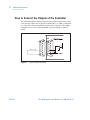
HOW to Connect the Open-Collector Inputs
of the Controller 260
How to Connect the Outputs of the Controller 264
J2 – Serial
265
RS 232/RS 485 Communication Description 266
Communication Format 266
Communication Protocol
266
Window-Meanings 271
Inlet Screen Installation
275
Heater Band Installation 278
Original Instructions
239/312
17 Technical Information
Air Cooling Kit Installation 280
TV 1001 with Navigator Controller 280
TV 1001 Pump with Standard Rack Controller 282
Water Cooling Kit Installation 284
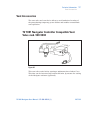
Vent Accessories 287
TV 1001 Navigator Controller Compatible Vent Valve
mod. 969-9834 287
Standard Rack Controller Compatible
Vent Valve mod. 969-9843 289
Vent Device mod. 969-9831 290
Vibration Isolator Installation
291
Purge Valve Installation
292
Serial Cable Installation
293
TV 1001 Controller Installation 294
Bottom Mounting 294
Side Mounting
296
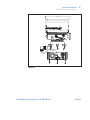
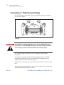
Connection A - High Vacuum Flange 298
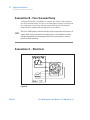
Connection B - Fore-Vacuum Pump 300
Connection C – Electrical 300
Pump Used with Corrosive Gases
302
Pump Used in Presence of Magnetic Fields 304
Accessories and Spare Parts 305
240/312
TV 1001 Navigator User Manual / 87-900-945-01 (I)
Technical Information
Description of the TV 1001 Navigator
17
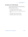
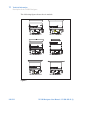
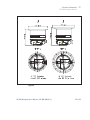
Description of the TV 1001 Navigator
The TV 1001 Navigator pumping system consists of a pump with a
dedicated controller fixed to it. The system is available in six models
that differ in the high vacuum flange.
The TV 1001 Navigator kit six models are:
Model 969-8838 with ISO 200 high vacuum flange;
Model 969-8844 with ISO 200 F high vacuum flange;
Model 969-8839 with ConFlat 10” external di-ameter high vacuum
flange;
Model 969-8840 with ISO 160 high vacuum flange;
Model 969-8841 with ISO 250 high vacuum flange;
Model 969-8845 with ISO 250 F high vacuum flange.
TV 1001 Navigator User Manual / 87-900-945-01 (I)
241/312
17 Technical Information
Description of the TV 1001 Navigator
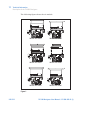
The following figure shows the six models.
Model 969-8838
Model 969-8844
Model 969-8839
Model 969-8840
Model 969-8841
Model 969-8845
Figure 1
242/312
TV 1001 Navigator User Manual / 87-900-945-01 (I)
Technical Information
Description of the TV 1001 Navigator
17
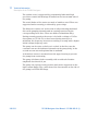
The pumps only are available with the following models:
Model 969-8931 with ISO 200 high vacuum flange;
Model 969-8946 with ISO 200 F high vacuum flange;
Model 969-8932 with ConFlat 10” external di-ameter high vacuum
flange;
Model 969-8933 with ISO 160 high vacuum flange;
Model 969-8934 with ISO 250 high vacuum flange;
Model 969-8947 with ISO 250 F high vacuum flange.
TV 1001 Navigator User Manual / 87-900-945-01 (I)
243/312
17 Technical Information
Description of the TV 1001 Navigator
The following figure shows the six models.
Model 969-8931
Model 969-8946
Model 969-8932
Model 969-8933
Model 969-8934
Model 969-8947
Figure 2
244/312
TV 1001 Navigator User Manual / 87-900-945-01 (I)
Technical Information
Description of the TV 1001 Navigator
17
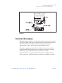
The controller model 969-8978 is also available as an option.
Figure 3
Controller model 969-8978
Pump Description
The pump consists of a high frequency motor driving a turbine fitted
with 8 bladed stages and 4 Macrotorr stages. The turbine rotates in
an anticlockwise direction when viewed from the high vacuum flange
end.
The turbine is made of high-strength aluminium al-loy, machined
from a single block.
Proceeding from the high vacuum to the for vacu-um region, the
turbine stages sequence is:
1st stage with a blade angle of 40°,
2nd stage with a blade angle of 34°,
3rd stage with a blade angle of 28°,
4th and 5th stages with a blade angle of 24°,
6th stage with a blade angle of 20°,
7th and 8th stages with a blade angle of 16°.
The Macrotorr stages are in the form of four discs.
TV 1001 Navigator User Manual / 87-900-945-01 (I)
245/312
17 Technical Information
Description of the TV 1001 Navigator
The turbine rotor is supported by permanently lubricated high
precision ceramic ball bearings in-stalled on the forevacuum side of
the pump.
The static blades of the stator are made of stainless steel. These are
supported and accurately po-sitioned by spacer rings.
The Macrotorr stators are in the form of self-positioning machined
discs with pumping channels and an opening restricted by the
corresponding rotor discs. These are made of aluminium alloy.
During normal operation, the motor is fed with a voltage of 54 Vac
three-phase at 715 Hz. To re-duce losses during start-up to a
minimum, the frequency increases according to a ramp with a higher
initial voltage/frequency ratio.
The pump can be water cooled or air cooled: in the first case the
customer can use the dedicated channels on the pump body, in the
second case an external optional fan is available.
A thermistor sensor is mounted near the upper bearing to prevent
the pump from overheating.
The pump is balanced after assembly with a resid-ual vibration
amplitude less than 0.01 m.
The pump can operate in any position and can be supported on the
high vacuum flange. The connection of the forevacuum on the side of
the pump is a KF 40 NW flange.
246/312
TV 1001 Navigator User Manual / 87-900-945-01 (I)
Technical Information
Description of the TV 1001 Navigator
17
Figure 4
Controller Description
The dedicated controller is a solid-state frequency converter which is
driven by a single chip micro-computer and is composed of two PCBs
which include power supply and 3-phase output, analog and
input/output section, microprocessor and digital section.
The power supply, together with the 3-phase out-put, converts the
single phase AC mains supply into a 3-phase, low voltage, medium
frequency output which is required to power the pump.
The controller can be operated by a remote host computer via the
serial connection. A Windows-based software is available (optional).
TV 1001 Navigator User Manual / 87-900-945-01 (I)
247/312
17 Technical Information
Technical Specification
Technical Specification
Tab. 3
Pumping speed (with inlet screen)
N2:
He:
H2:
ISO 160:
790 l/s
820 l/s
860 l/s
CFF 10"/ ISO 200:
950 l/s
870 l/s
900 l/s
Compression ratio
N2:
>1 x 10⁹
1 x 10⁹
He:
5 x 10⁷
1 x 10⁷
H2:
106
1 x 10⁶
2x
Base pressure
< 1 x 10⁻¹⁰ mbar
with recommended forepump
(< 1 x 10⁻¹⁰ Torr)
ISO 250:
1050 l/s
900 l/s
920 l/s
(According to standard DIN 28 428, the base pressure is that
measured in a leak-free test dome, 48 hours after the completion of
test dome bake-out, with a Turbopump fitted with a ConFlat flange
and using the recommended pre-vacuum pump)
Inlet flange
ISO 160, ISO 200, ISO 250 CF 10"
Foreline flange
KF 40 NW
Rotational speed
38000 rpm
Start-up time
4 minutes
Recommended forepump
DS 402, TriScroll 300
Operating position
Any
Operating ambient temperature
+5 °C to +35 °C
Bakeout temperature
120 °C at inlet flange max. (CF flange)
80 °C at inlet flange max. (ISO flange)
Vibration level (displacement)
0.01 Pm at inlet flange
Lubricant
permanent lubrication
Cooling requirements
Forced air or water
Coolant water
Minimum flow: 200 l/h (0.89 GPM)
Temperature: +10 °C to +20 °C
Pressure: 3 to 5 bar (45 to 75 psi)
Noise level
<45 dB(A) at 1 meter
248/312
TV 1001 Navigator User Manual / 87-900-945-01 (I)
Technical Information
Technical Specification
Power supply:
Input voltage:
Input freq.:
Max input power:
Stand-by power:
Max operating
power:
17
100 - 240 Vac
50 - 60 Hz
600 VA
30 to 35 W
450 W with water cooling
300 W with air cooling
Protection fuse
1 x 6.3 A
Compliance with:
UNI EN 292-1
UNI EN 292-2
EN-CENELEC 55011
IEC 1000-4-2 (ex 801-2)
IEC 1000-4-3 (ex 801-3)
IEC 1000-4-4 (ex 801-4)
EN 61010-1 (IEC 1010-1)
EN 1012-2
Power cable
With European or NEMA plug
3 meters long (optional)
Serial communication (Navigator
kit)
RS232 cable with a 9-pin D type male connector and a 9-pin D type
female connector, and Navigator software (optional)
Installation category
II
Pollution degree
2
Storage temperature
-20 °C to +70 °C
Weight kg (lbs)
ISO 160 flange
ISO 200 flange
ISO 250 flange
CF 10“ flange
19 (41.8)
19.4 (43)
21.2 (46.6)
25.5 (54.2)
Controller
NOTE
5.4 (12)
When the TV 1001 Navigator has been stored at a temperature
less than 5 °C, wait until the system has reached the above
mentioned temperature.
TV 1001 Navigator User Manual / 87-900-945-01 (I)
249/312
17 Technical Information
TV 1001 Navigator Outline
TV 1001 Navigator Outline
The following figures show the TV 1001 Navigator outlines
(dimensions are in mm [inches]).
Figure 5
250/312
TV 1001 Navigator User Manual / 87-900-945-01 (I)
Technical Information
TV 1001 Navigator Outline
17
Figure 6
TV 1001 Navigator User Manual / 87-900-945-01 (I)
251/312
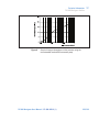
17 Technical Information
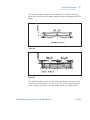
TV 1001 Navigator Outline
252/312
Figure 7
Graph of nitrogen pumping speed vs inlet pressure
Figure 8
Graph of compression ratio vs foreline pressure
TV 1001 Navigator User Manual / 87-900-945-01 (I)
Technical Information
TV 1001 Navigator Outline
Figure 9
17
Graph of nitrogen throughput vs inlet pressure using the
recommended mechanical forevacuum pump
TV 1001 Navigator User Manual / 87-900-945-01 (I)
253/312
17 Technical Information
Interconnections
Interconnections
The following figure shows the TV 1001 interconnections.
Figure 10
254/312
TV 1001 Navigator User Manual / 87-900-945-01 (I)
Technical Information
Interconnections
17
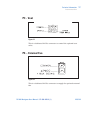
P3 - Vent
Figure 11
This is a dedicated 24 Vdc connector to control the optional vent
valve.
P4 – External Fan
Figure 12
This is a dedicated 24 Vdc connector to supply the optional external
fan.
TV 1001 Navigator User Manual / 87-900-945-01 (I)
255/312
17 Technical Information
Interconnections
J1 – In-Out
Figure 13
This connector carries all the input and output sig-nals to remote
control the TV 1001 Navigator.
It is a 15-pins D type connector; the available sig-nals are detailed in
the table, the following para-graphs describe the signal
characteristics and use.
Tab. 4
256/312
Pin N.
Signal name
In-/Output
1
START/STOP (+)
IN
2
START/STOP (-)
IN
3
INTERLOCK (+)
IN
4
INTERLOCK (-)
IN
5
SPEED SETTING (+)
IN
6
SPEED SETTING (-)
IN
7
SOFT START (+)
IN
8
SOFT START (-)
IN
9
+24 Vdc
OUT
10
SPARE
11
PROGRAMMABLE SET POINT
12
SPARE
13
FAULT OUTPUT
OUT
14
PROGRAMMABLE ANALOG SIGNAL (+)
OUT
15
GROUND
PROGRAMMABLE ANALOG SIGNAL (-)
OUT
OUT
TV 1001 Navigator User Manual / 87-900-945-01 (I)
Technical Information
Interconnections
17
Signal Description
Start/Stop: input signal to start or stop the pump. With the supplied
cover connector the START/STOP (+) signal is connected to the +24
Vdc pin and the START/STOP (-) signal to the GROUND pin: in this
condition the pump automatically starts as soon as the controller
recognises the input supply ("Plug & Pump").
Interlock: input signal to control the pump rotation. With the
supplied cover connector the interlock (+) signal is connected to the
+24 Vdc pin and the interlock (-) signal to the GROUND pin.
Speed setting: PWM input signal to set the pump speed. The PWM
signal characteristics must be the following:
frequency: 100 Hz +/-20 %
amplitude: 24 V max
duty cycle range: from 25 % to 75 %
corresponding to an output frequency from 272 Hz to 633 Hz (see
the following diagram):
Figure 14
NOTE
The duty cycle percentage is referred to the low level portion of the PWM signal
TV 1001 Navigator User Manual / 87-900-945-01 (I)
257/312
17 Technical Information
Interconnections
Programmable analog signal: this output signal is a voltage (from 0
to 10 Vdc) proportional to a reference quantity (frequency or power)
set by the user. The default setting is the frequency (see the following
example diagram).
Figure 15
Fault: this open collector output signal is ON when a system fault
condition is detected.
Programmable set point: this open collector output signal is enabled
when the reference quantity chosen (frequency, current or time) is
higher than the set threshold. The signal can be "high level active" (that
is the output is normally at 0 Vdc and becomes 24 Vdc when activated),
or "low level active" (that is the output is normally at 24 Vdc and
becomes 0 Vdc when activated). Moreover, if the reference quantity is
the frequency or the current drawn, it is possible to set the hysteresis
(in % of the threshold value) to avoid bouncing.
For example:
258/312
reference quantity: frequency
threshold: 500 Hz
hysteresis: 1 %
activation type: "high level"
TV 1001 Navigator User Manual / 87-900-945-01 (I)
Technical Information
Interconnections
17
Figure 16
The set point output stays at 0 Vdc until the fre-quency becomes
higher than 505 Hz (that is 500 Hz + 1 % of 500 Hz), then the output
goes at 24 Vdc and stays at 24 Vdc until the frequency be-comes
lower than 495 Hz (that is 500 Hz – 1 % of 500 Hz).
It is possible to delay the set point checking for a programmable
delay time.
The PROGRAMMABLE SET POINT signal has the following default
settings:
NOTE
reference quantity: frequency
threshold: 643 Hz
hysteresis: 2 %
activation type: high level
delay time: 0 second
The Navigator Software (optional) allows the oper-ator to set all the
programmable feature.
When no external input-output device is available this connector
must be closed with the supplied mating connector that short-circuits
the START and INTERLOCK inputs with the GROUND input (see the
following figure).
TV 1001 Navigator User Manual / 87-900-945-01 (I)
259/312
17 Technical Information
Interconnections
Figure 17
How to Connect the Open-Collector Inputs
of the Controller
Here below there are the typical connections of the open collector
input of TV551/701 Navigator to an external system. Two cases are
considered:
1.
the customer supplies the 24 Vdc
2.
the customer does not supply the 24 Vdc.
Please note that on the connector a 24 Vdc, 60 mA voltage, a
GROUND signal and the open col-lector pin are available.
260/312
TV 1001 Navigator User Manual / 87-900-945-01 (I)
Technical Information
Interconnections
Figure 18
17
Case 1
TV 1001 Navigator User Manual / 87-900-945-01 (I)
261/312
17 Technical Information
Interconnections
Figure 19
262/312
Case 2 with relay utilisation
TV 1001 Navigator User Manual / 87-900-945-01 (I)
Technical Information
Interconnections
Figure 20
17
Case 2 with transistor utilization
TV 1001 Navigator User Manual / 87-900-945-01 (I)
263/312
17 Technical Information
Interconnections
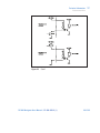
How to Connect the Outputs of the Controller
The following figure shows a typical logic output connection (relay
coil) but any other device may be connected e.g. a LED, a computer,
etc., and the related simplified circuit of the controller. The figure
example refers to the programmable set point signal on pins 11
and 9.
Figure 21
264/312
Typical output connection
TV 1001 Navigator User Manual / 87-900-945-01 (I)
Technical Information
Interconnections
17
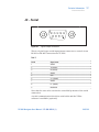
J2 – Serial
Figure 22
Typical output connection
This is a 9 pin D-type serial input/output connector to control via an
RS 232 or RS 485 connection the TV 1001.
Tab. 5
Pin N.
Signal name
1
SPARE
2
TX (RS232)
3
RX (RS232)
4
SPARE
5
GND
6
A + (RS485)
7
SPARE
8
B – (RS485)
9
RESERVED
Note that the vent valve can also be controlled by means of the serial
connection.
A serial communication kit with a serial cable and the T-Plus
software is available (optional).
TV 1001 Navigator User Manual / 87-900-945-01 (I)
265/312
17 Technical Information
RS 232/RS 485 Communication Description
RS 232/RS 485 Communication Description
Both the RS 232 and the RS 485 interfaces are available on the
connector J2.
The communication protocol is the same (see the structure below),
but only the RS 485 manages the address field. Therefore to enable
the RS 485 is necessary to select the type of communication as well
as the device address by means of the Navigator software.
Communication Format
8 data bit
no parity
1 stop bit
baud rate: 600/1200/2400/4800/9600 programmable
Communication Protocol
The communication protocol is a MASTER/SLAVE type where:
Host = MASTER
Controller = SLAVE
The communication is performed in the following way:
1.
the host (MASTER) send a MESSAGE + CRC to the controller
(SLAVE);
2.
the controller answer with an ANSWER + CRC to the host.
The MESSAGE is a string with the following format:
<STX>+<ADDR>+<WIN>+<COM>+<DATA>+<ETX>+<CRC>
where:
266/312
TV 1001 Navigator User Manual / 87-900-945-01 (I)
Technical Information
RS 232/RS 485 Communication Description
NOTE
17
When a data is indicated between two quotes (‘...’) it means that the indicated
data is the corresponding ASCII character.
<STX> (Start of transmission) = 0x02
<ADDR> (Unit address) = 0x80 (for RS 232)
<ADDR> (Unit address) = 0x80 + device number (0 to 31) (for RS
485)
<WIN> (Window) = a string of 3 numeric char-acter indicating the
window number (from ‘000’ to ‘999’); for the meaning of each
window see the relevant paragraph.
<COM> (Command) = 0x30 to read the window, 0x31 to write into
the window
<DATA> = an alphanumeric ASCII string with the data to be
written into the window. In case of a reading command this field
is not present
The field length is variable according to the data type as per the
following table:
Tab. 6
Data type
Field length
Valid characters
Logic (L)
1
‘0’ = OFF
‘1’ = ON
Numeric (N)
6
‘-‘, ‘.’, ‘0’ . . . ‘9’ right
justified with ‘0’
Alphanumeric (A)
10
from blank to ‘_’ (ASCII)
<ETX> (End of transmission) = 0x03
<CRC> = XOR of all characters subsequent to <STX> and
including the <ETX> terminator. The value is hexadecimal coded
and indicated by two ASCII character.
The addressed SLAVE will respond with an ANSWER whose
structure depends from the MESSAGE type.
TV 1001 Navigator User Manual / 87-900-945-01 (I)
267/312
17 Technical Information
RS 232/RS 485 Communication Description
When the MESSAGE is a reading command, the SLAVE will respond
transmitting a string with the same structure of the MESSAGE.
NOTE
Using the RS 485 interface, the message structure remains identical to the one
used for the RS 232 interface, the only difference being that the value assigned
to the ADDRESS <ADDR>
The controller can answers with the following response types:
Tab. 7
Type
Length
Value
Description
Logic
1 byte
-
After a read instruction of a logic
window
Numeric
6 bytes
-
After a read instruction of a numeric
window
Alphanumeric
10 bytes
-
After a read instruction of an
alphanumeric window
ACK
1 byte
(0x6)
The command execution has been
successfully completed
NACK
1 byte
(0x15)
The command execution has been
failed
Unknown
Window
1 byte
(0x32)
The specified window in the
command is not a valid window
(0x33)
The data type specified in the
command (Logic, Numeric or
Alphanumeric) is not accorded with
the specified Window
Data Type Error
1 byte
Out of Range
1 byte
Win Disabled
268/312
1 byte
(0x34)
(0x35)
The value expressed during a write
command is out of the range value
of the specified window
The specified window is Read Only
or temporarily disabled (for example
you can’t write the Soft Start when
the Pump is running)
TV 1001 Navigator User Manual / 87-900-945-01 (I)
Technical Information
RS 232/RS 485 Communication Description
17
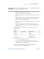
Examples
Command: START
Source: PC
Destination: Controller
02
80
30
30
STX
ADDR
WINDOW
30
31
31
03
42
WR
ON
ETX
CRC
31
30
03
42
WR
OFF
ETX
CRC
33
Source: Controller
Destination: PC
02
80
06
03
38
STX
ADDR
ACK
ETX
CRC
35
Command: STOP
Source: PC
Destination: Controller
02
80
30
30
STX
ADDR
WINDOW
30
32
Source: Controller
Destination: PC
02
80
06
03
38
STX
ADDR
ACK
ETX
CRC
35
TV 1001 Navigator User Manual / 87-900-945-01 (I)
269/312
17 Technical Information
RS 232/RS 485 Communication Description
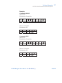
Command: SOFT-START (ON)
Source: PC
Destination: Controller
02
80
31
30
STX
ADDR
WINDOW
30
31
31
03
42
WR
ON
ETX
CRC
32
Source: Controller
Destination: PC
02
80
06
03
38
STX
ADDR
ACK
ETX
CRC
35
Command: SOFT-START (OFF)
Source: PC
Destination: Controller
02
80
31
30
STX
ADDR
WINDOW
30
31
30
03
42
WR
OFF
ETX
CRC
33
Source: Controller
Destination: PC
270/312
02
80
06
03
38
STX
ADDR
ACK
ETX
CRC
35
TV 1001 Navigator User Manual / 87-900-945-01 (I)
Technical Information
RS 232/RS 485 Communication Description
17
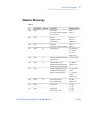
Window-Meanings
Tab. 8
N.
Read/Write
Datatype
Description
Admitted Values
000
R/W
L
Start/Stop
(in remote mode the window
is a read only)
Start = 1
Stop = 0
008
R/W
L
Remote
(default) or Serial
configuration
Remote = 1
Serial = 0
(default = 1)
100
R/W
L
Soft Start
(write only in Stop condition)
YES = 1
NO = 0
101
R/W
N
Set Point type
0 = Frequency
1 = Current
2 = Time
102
R/W
N
Set Point threshold (expressed
in Hz, mA or s)
(default = 582)
103
R/W
N
Set Point delay: time
between the pump start and
the set point check (seconds)
0 to 99999
Set Point signal activation type:
the signal can be "high level
active" or "low level active"
0 = high level
active
1 = low level
active
(default = 0)
104
R/W
L
(default = 0)
(default = 0)
105
R/W
N
Set point hysteresis
(in % of threshold)
0 to 100
(default = 2)
106
R/W
L
Intercooling
0 = NO
1 = YES
107
R/W
L
Active Stop
(write only in stop)
0 = NO
1 = YES
TV 1001 Navigator User Manual / 87-900-945-01 (I)
271/312
17 Technical Information
RS 232/RS 485 Communication Description
N.
Read/Write
Datatype
Description
Admitted Values
108
R/W
N
Baud rate
600 = 0
1200 = 1
2400 = 2
4800 = 3
9600 = 4
(default = 4)
109
W
L
Pump life/ cycle time/ cycle
number reset
To reset write
‘1’
110
R/W
L
Interlock type
(default = 1)
Impulse = 0
Continuous = 1
111
R/W
L
Analog output type: output
voltage signal proportional to
frequency or power
0 = frequency
1 = power
Rotational frequency setting
(Hz)
150 to 646
Maximum rotational
frequency in Hz (active only
in Stop condition)
150 to 646
Set vent valve on/off
(on = closed)
On = 1
Off = 0
120
121
122
R/W
R/W
R/W
N
N
L
(default = 0)
(default = 646)
(default = 646)
(default = 1)
123
124
Reserved to Agilent service
125
R/W
L
Set the vent valve
operation
Automatic = 0
(see note 1.)
On command =
1 (see note 2.)
126
272/312
R/W
N
Vent valve opening
delay
(expressed in 0.2 sec)
130
Reserved to Agilent service
200
R
N
Pump
current in mA dc
201
R
N
Pump voltage in Vdc
0 to 65535
(corresponding
to 0 to 13107
sec)
TV 1001 Navigator User Manual / 87-900-945-01 (I)
Technical Information
RS 232/RS 485 Communication Description
17
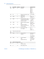
N.
Read/Write
Datatype
Description
202
R
N
Pump power in W (pump
current x pump voltage duty
cycle)
203
R
N
Driving frequency in Hz
204
R
N
Pump temperature in °C
0 to 70
205
R
N
Pump status
Stop = 0
Waiting intlk = 1
Starting = 2
Auto-tuning = 3
Braking = 4
Normal = 5
Fail = 6
206
R
N
Error code
Bit description:
see the
following figure
300
R
N
Cycle time in minutes
(zeroed by the reset
command)
0 to 999999
301
R
N
Cycle number (zeroed by the
reset command)
0 to 9999
302
R
N
Pump life in hours (zeroed by
the reset command)
0 to 999999
320
to
399
Reserved to Agilent service
400
R
A
CRC EPROM (QE)
QE5XXXX
(where “XXXX”
are variable)
402
R
A
CRC Param. (PA)
PA5XXXX
(where “XXXX”
are variable)
500
Reserved to Agilent service
503
R/W
N
RS 485 address
Admitted Values
0 to 31
(default = 0)
504
R/W
L
Serial type select
TV 1001 Navigator User Manual / 87-900-945-01 (I)
0 = RS 232
1 = RS 485
273/312
17 Technical Information
RS 232/RS 485 Communication Description
N.
Read/Write
Datatype
Description
Admitted Values
(default = 0)
NOTE
1. Automatic means that when the controller stops, the vent valve is opened
with a delay defined by window n. 126; when the controller starts, the vent valve
is immediately closed.
2. On command means that the vent valve is opened or closed by means of
window n. 122.
7
6
5
4
3
2
TOO HIGH LOAD
OVERVOLTAGE
AUX FAIL
274/312
0
NO CONNECTION
SHORT CIRCUIT
Figure 23
1
PUMP OVERTEMP.
CONTROLL. OVERTEMP.
POWER FAIL
Window N. 206 Bit Description
TV 1001 Navigator User Manual / 87-900-945-01 (I)
Technical Information
Inlet Screen Installation
17
Inlet Screen Installation
Figure 24
Figure 25
Figure 26
TV 1001 Navigator User Manual / 87-900-945-01 (I)
275/312
17 Technical Information
Inlet Screen Installation
The inlet screens mod. 969-9304, 969-9316 and 969-9350 prevent the
blades of the pump from being damaged by debris greater than 0.7
mm diameter.
The inlet screen, however, does reduce the pumping speed by about
10 %.
The inlet screen is fitted in the upper part of the pump, as shown in
the figure.
Figure 27
The screen can be mounted on each pump. The screen can be
removed as shown in the following figure.
Figure 28
276/312
TV 1001 Navigator User Manual / 87-900-945-01 (I)
Technical Information
Inlet Screen Installation
17
The following figure shows the overall flange di-mensions with the
protection screen fitted on pump with ISO flange and pump with CFF
flange.
Figure 29
Figure 30
The following figure shows the ISO 250 pump flange section with the
protection screen fitted on it. As you can see, the overall dimensions
do not change as the inlet screen remains inside the pump profile.
TV 1001 Navigator User Manual / 87-900-945-01 (I)
277/312
17 Technical Information
Heater Band Installation
Figure 31
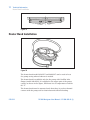
Heater Band Installation
Figure 32
The heater band model 969-9317 and 969-9327 can be used to heat
the pump casing when a bakeout is needed.
The heater band is available only for the pump with ConFlat inlet
flange (model 969-8932). It is applied to the upper part of the pump
casing, as shown in the figure, and heats it to a temperature of about
80° C.
The heater band must be mounted such that there is perfect thermal
contact with the pump wall to obtain fast and efficient heating.
278/312
TV 1001 Navigator User Manual / 87-900-945-01 (I)
Technical Information
Heater Band Installation
17
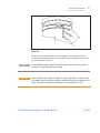
Figure 33
Switch on the heater while the turbopump is in operation. In the
event of turbopump overheat, the pump will be automatically cut out
by the thermistor sensor.
NOTE
CAUTION!
The turbopump must be "baked" only when operat-ing with an inlet pressure
less than 10-4 mbar and with water cooling.
If the chamber of the system is "baked" at a high temperature, a shield should
be installed to pre-vent thermal radiation heating the high vacuum flange on the
pump. The maximum temperature allowed for the inlet flange is 120° C.
TV 1001 Navigator User Manual / 87-900-945-01 (I)
279/312
17 Technical Information
Air Cooling Kit Installation
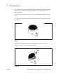
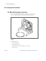
Air Cooling Kit Installation
TV 1001 with Navigator Controller
An air cooling kit (mod. 969-9297) is available to improve the TV
1001 cooling during heavy operational conditions (optional).
Figure 34
Fan specifications:
280/312
air flow: 200m3/h
input voltage: 24 Vdc
dimensions: 127 x 127 x 38 mm (5 x 5 x 1.5 in.)
power: 4.7 W
TV 1001 Navigator User Manual / 87-900-945-01 (I)
Technical Information
Air Cooling Kit Installation
17
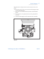
The fan bracket is shaped so that it can be mount-ed close to the
pump.
To fix the fan to the TV 1001 case execute the fol-lowing procedure
(see the following figure):
1
Fix the fan to the suitable bracket by means of the furnished
screws;
2
Fix the bracket to the pump body between the pump and the
controller;
3
Connect the fan supply to the P4 connector of the controller.
Figure 35
TV 1001 Navigator User Manual / 87-900-945-01 (I)
281/312
17 Technical Information
Air Cooling Kit Installation
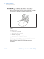
TV 1001 Pump with Standard Rack Controller
When the TV 1001 pumps are used with the standard rack controller,
it is necessary to utilize the air cooling kit model 969-9315.
Figure 36
Fan specification:
air flow: 55 l/s (120 CFM)
input voltage: 120 Vac 50-60 Hz
maximum power: 17 W
dimensions: 127 x 127 mm (5 x 5 inches)
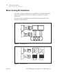
To fix the fan to the pump, position it ensuring that the holes in the
plate line up with those in the pump base.
Insert the respective washers and screws and tighten with a
screwdriver.
282/312
TV 1001 Navigator User Manual / 87-900-945-01 (I)
Technical Information
Air Cooling Kit Installation
17
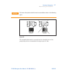
Connect the fan to the controller.
Figure 37
TV 1001 Navigator User Manual / 87-900-945-01 (I)
283/312
17 Technical Information
Water Cooling Kit Installation
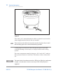
Water Cooling Kit Installation
Two types of water cooling kits are available to be mounted when the
pump is used under heavy load conditions or when air cooling is
insufficient.
The two model part numbers are: 969-9337 (metal-lic model), and
969-9347 (plastic model).
284/312
Figure 38
Model 969-9337
Figure 39
Model 969-9347
TV 1001 Navigator User Manual / 87-900-945-01 (I)
Technical Information
Water Cooling Kit Installation
CAUTION!
17
The items of the plastic model kit must be assem-bled as shown in the following
figure
Figure 40
The assembled kit must be screwed into the suita-ble holes of the
pump body with a recommended closing torque of 5 Nm.
TV 1001 Navigator User Manual / 87-900-945-01 (I)
285/312
17 Technical Information
Water Cooling Kit Installation
Figure 41
Two 6 mm (1/4") internal diameter rubber or plastic hoses from the
water supply must be fitted to the two nozzles.
NOTE These hoses must be held on the respective nozzles using hose clips to avoid
that the tube(s) gets loose or disconnected during operation.
Cooling may be carried out either through an open circuit with
eventual discharge of the water, or using a closed circuit cooling
system.
The water temperature must be between +10°C and +20°C, with an
inlet pressure between 3 and 5 bar. This allows a flow of about 200
l/h.
NOTE
286/312
The water electrical conductance must be 500 μs/cm. When the conductance
is higher, in closed water circuit, the use of up to 20 % of Ethyl-Glycole is
suggested.
TV 1001 Navigator User Manual / 87-900-945-01 (I)
Technical Information
Vent Accessories
17
Vent Accessories
The vent valve and vent device allow to avoid undesired venting of
the pump during temporary power failure and enables an automatic
vent operation.
TV 1001 Navigator Controller Compatible Vent
Valve mod. 969-9834
Figure 42
This vent valve waits before opening a minimum time of about 5 sec.
This time can be increased up to about 220 min. by means of a setting
of the Navigator software (optional).
TV 1001 Navigator User Manual / 87-900-945-01 (I)
287/312
17 Technical Information
Vent Accessories
To install the vent valve, unscrew the threaded plug (see figure
below).
Figure 43
Then screw the vent valve into the pump and tight-en it using a 16
mm hexagonal spanner with a torque of 2.5 Nm.
Figure 44
288/312
TV 1001 Navigator User Manual / 87-900-945-01 (I)
Technical Information
Vent Accessories
CAUTION!
17
Do not overtighten the valve as this may damage the thread on the pump.
Then connect the cable from the valve to the suita-ble connector on
the controller (see the preceding paragraph “INTERCONNECTIONS”).
Standard Rack Controller Compatible
Vent Valve mod. 969-9843
Figure 45
This vent valve has a fixed delay time of about 5 sec. This value can
be used only with rack controller.
To install the vent valve execute the same steps as the vent valve
model 969-9834 (see the above paragraph).
TV 1001 Navigator User Manual / 87-900-945-01 (I)
289/312
17 Technical Information
Vent Accessories
Vent Device mod. 969-9831
Figure 46
The vent device has adjustable delay time (up to 36 min.). This value
can be used only with rack controller. To install the vent device
unscrew and remov e the threaded plug (see figure below).
Figure 47
Screw the flange mod. 969-9108 on the pump, tak-ing care of the oring right position.
290/312
TV 1001 Navigator User Manual / 87-900-945-01 (I)
Technical Information
Vibration Isolator Installation
17
Assemble the seal ring and lock the vent device in position using the
KF klamp.
Figure 48
Vibration Isolator Installation
Three vibration isolators for ISO and CFF inlet flange version pumps
are available as accessories.
The three model part numbers are the following:
model 969-9345 for ISO 160 flange;
model 969-9346 for ISO 200 flange;
model 969-9336 for CFF 10” flange.
They typically reduce the vibration transmitted from the TV 1001
Navigator to the system by a factor of 20.
Please refer to the relevant instruction manual.
TV 1001 Navigator User Manual / 87-900-945-01 (I)
291/312
17 Technical Information
Purge Valve Installation
Purge Valve Installation
A gas purge valve is available to protect the pump bearings against
particulate and corrosive gases that could move into the pump.
To install the gas purge valve it is necessary to unscrew the purge
port cover as shown in the following figure,
Figure 49
and then screw the gas purge valve (with a torque of 2.5 Nm) as
shown in the following figure.
Figure 50
292/312
TV 1001 Navigator User Manual / 87-900-945-01 (I)
Technical Information
Serial Cable Installation
17
Serial Cable Installation
The supplied serial cable must be installed when the TV 1001
Navigator or the optional vent valve have to be controlled by means
of a remote computer.
The cable is installed fixing the 9 pin D-type connector into the P2
serial connector as shown in the following figure.
Figure 51
TV 1001 Navigator User Manual / 87-900-945-01 (I)
293/312
17 Technical Information
TV 1001 Controller Installation
TV 1001 Controller Installation
The controller can be mounted in two position:
bottom mounting (as per the complete system)
side mounting.
To install the controller execute the following procedures.
Bottom Mounting
See the following figure.
294/312
1
Turn the pump upside-down;
2
Place the three fixing blocks with the through holes toward the
inside, and fix them with the three M6 screws to the pump
bottom;
3
Place the controller on the blocks, with the pump cable toward
the pump body;
4
Fix the controller to the blocks by means of the three socket head
screws M5;
5
Turn the pump again;
6
Plug the line card and connect the pump cable to the pump;
7
Connect the mating connector with the jumper on the interlock
signal to start the pump.
TV 1001 Navigator User Manual / 87-900-945-01 (I)
Technical Information
TV 1001 Controller Installation
17
Figure 52
TV 1001 Navigator User Manual / 87-900-945-01 (I)
295/312
17 Technical Information
TV 1001 Controller Installation
Side Mounting
NOTE The L-shaped bracket (P/N 969-9298) is available as an option.
See the following figure.
296/312
1
Place the L-shaped bracket on the controller, with the pump
cable toward the bracket, and fix it by means of the three socket
head screws M5, the washers and the nuts. The 6 holes on the
bracket allows to mount the controller with the rotation angle
that you like;
2
Turn the pump upside-down;
3
Place the bracket on the pump bottom (the hole on the bracket
has the same diameter as the pump bottom flange);
4
Screw a little bit the three screws M6 in the holes on the pump
bottom;
5
Rotate the bracket until the controller is on the chosen position;
6
Tighten the screws properly;
7
Turn the pump again;
8
Plug the line card and connect the pump cable to the pump;
9
Connect the mating connector with the jumper on the interlock
signal to start the pump.
TV 1001 Navigator User Manual / 87-900-945-01 (I)
Technical Information
TV 1001 Controller Installation
17
Figure 53
TV 1001 Navigator User Manual / 87-900-945-01 (I)
297/312
17 Technical Information
TV 1001 Controller Installation
Connection A - High Vacuum Flange
For ISO-K flange connections, fix the two flanges with the clamps as
shown in the figure.
Figure 54
WARNING!
It is mandatory to connect the pump in such a way to withstand the torque
specified in the "IN-STRUCTION FOR USE" section. Specifically pay attention
to clamp design, material of clamps and bolts and bolt fixing torque
For ConFlat flange connections we recommend using Agilent
hardware.
To facilitate assembly and dismantling, apply Fel-pro C-100 high
temperature lubricant to the screw threads protruding from the
flange and between the nuts and flange.
Note that the connections can be made only with the bolt in the lower
side.
Attach the units and tighten each one in turn. Re-peat the sequential
tightening until the flange faces meet.
298/312
TV 1001 Navigator User Manual / 87-900-945-01 (I)
Technical Information
TV 1001 Controller Installation
CAUTION!
17
Exercise care when tightening nuts and bolts to avoid creating dents in the
envelope as this may cause the pump rotor to lock.
Connection Configurations
Figure 55
TV 1001 Navigator User Manual / 87-900-945-01 (I)
299/312
17 Technical Information
TV 1001 Controller Installation
Connection B - Fore-Vacuum Pump
A flange KF 40 NW is available to connect the Turbo V1001 pump to
the fore-vacuum pump. A hose or vacuum approved pipe can be used.
If a rigid pipe is used, any vibration generated by the mechanical
pump must be eliminated through the use of bellows.
NOTE The Turbo V1001 pump is characterized by its high compression ratio also for oil
vapors. When using a mechanical oil-sealed pump, it is advisable to in-stall a
suitable trap between the turbopump and the fore-vacuum pump in order to
prevent oil back-streaming.
Connection C – Electrical
Figure 56
300/312
TV 1001 Navigator User Manual / 87-900-945-01 (I)
Technical Information
TV 1001 Controller Installation
17
The turbopump is connected to the controller through an 8-pin
connector. Pins B, C and D are the 3-phase supply to the motor, pins
A and F are connected to the temperature sensor (NTC type, 30 K:
resistance at 25° C) and pin E is connected to the pump ground; pins
G and H are not connected.
If the temperature sensor is disconnected, the pump will not start. To
prevent damage to the pump when the temperature exceeds 60° C,
the sensor automatically cuts out the power supply.
TV 1001 Navigator User Manual / 87-900-945-01 (I)
301/312
17 Technical Information
Pump Used with Corrosive Gases
Pump Used with Corrosive Gases
To prevent damage to the bearings, an inert gas must flow into the
pump body around the upper bearing towards the forevacuum line.
To supply the inert purge gas (e. g. nitrogen) to the pump through the
purge port, connect a gas purge valve between the pressure regulator
and the pump.
Adjust the pressure regulator in order to read a gas flow rate of 0.1 to
0.8 mbar l/s.
CAUTION!
To prevent bearing damage, Agilent suggests a minimum purge gas flow rate of
10 sccm (0.17 mbar l/s). This value can be exceeded, according to the process
requirements. Please contact Agilent for specific applications.
The purge gas throughput with the recommended forepump of 15 m3
/h (11 CFM) allows to achieve a high vacuum pressure in the 10-8
mbar range.
The recommended gas flow maintains a pressure into the pump body
higher than the forevacuum pressure.
The recommended procedure to vent the system and the pump
avoiding the contact between the pump bearings and the corrosive
gas is described in the following points:
302/312
1
Close the corrosive gas flow into the system.
2
Leaving the Turbo-V pump and the backing pump running and
the purge gas flowing, wait for enough time to evacuate the
corrosive gas from the system.
3
Turn off the Turbopump.
4
Open the Turbo-V vent port slowly until to reach atmospheric
pressure in the system.
5
When the Turbo-V pump and the backing pump are stopped and
the system is at atmospheric pressure, for a better bearing
protection it is advisable to leave the purge gas flowing into the
Turbo-V pump, with the chamber or the Turbo-V vent valve
opened, to avoid system overpressures. If the vent valve can’t be
kept opened, the backing pump should be left operating.
TV 1001 Navigator User Manual / 87-900-945-01 (I)
Technical Information
Pump Used with Corrosive Gases
Figure 57
17
Purge layout
1
Purge gas line
2
Pressure regulator
3
Gas purge valve
4
Gas purge port
5
Forevacuum pump
6
Turbopump
7
Vent valve
TV 1001 Navigator User Manual / 87-900-945-01 (I)
303/312
17 Technical Information
Pump Used in Presence of Magnetic Fields
Pump Used in Presence of Magnetic Fields
Magnetic fields induce eddy currents in the rotor of a turbomolecular
pump that tend to oppose to its rotation.
The result is increased electrical power consump-tion by the motor,
most of which is dissipated in the rotor.
Since the rotor is not in contact with the stator the above power can
leave the rotor mainly by radia-tion and hence the rotor may be
overheated while static parts of the pump remain cool.
This effect is strongly dependant from the inten-sity, time function
and distribution of the magnetic field.
In general, therefore, an increase in pump current can be expected.
If this increase is lower than 50 % of the current value drawn by the
motor in high vacuum opera-tion, no particular problem should be
expected.
However if the effect is grater, than the case should be carefully
reviewed by Agilent’s specialist. As a matter of fact, in case of high
magnetic fields, also important forces might be generated and applied
to the rotor.
304/312
TV 1001 Navigator User Manual / 87-900-945-01 (I)
Technical Information
Accessories and Spare Parts
17
Accessories and Spare Parts
Tab. 9
Description
Part number
Mains cable NEMA Plug, 3m long
969-9958
Mains cable European Plug, 3m long
969-9957
Serial cable and Navigator Software
969-9883
Bracket for controller side mounting
969-9298
Inlet screen ISO 160
969-9304
Inlet screen ISO 200 and CFF 10”
969-9316
Inlet screen ISO 250
969-9350
Heater band, 220 V
969-9327
Heater band, 120 V
969-9317
Water cooling kit (plastic model)
969-9347
Water cooling kit (metallic model)
969-9337
Air cooling kit for Navigator Controller
969-9297
Air cooling kit for standard rack controller
969-9315
Vibration isolator, ISO 160
969-9345
Vibration isolator, ISO 200
969-9346
Vibration isolator, CF 10"
969-9336
Vent flange, NW 10 KF / M8
969-9108
Vent device with adjustable delay time for standard rack controller
969-9831
Vent valve for standard rack controller
969-9843
Vent valve for Navigator Controller
969-9834
Purge valve with KF16 flange
969-9239
Purge valve with 7/16” flange
969-9240
Purge valve KF16-M12 20 SCCM
969-9241
Purge valve 7/16-M12 20 SCCM
969-9242
Forepump DS 402, with 1 ph. / 3 ph., universal motor
949-9382
Triscroll Dry Vacuum Pump PTS 300 single phase, universal motor
PTS03001UNIV
Triscroll Dry Vacuum Pump PTS 300 3 phase, universal motor
PTS03003UNIV
TV 1001 Navigator User Manual / 87-900-945-01 (I)
305/312
17 Technical Information
Accessories and Spare Parts
306/312
TV 1001 Navigator User Manual / 87-900-945-01 (I)
Request for Return Form
Sales and Service Offices
United States
Agilent Technologies
Vacuum Products Division
121 Hartwell Avenue
Lexington, MA 02421 - USA
Tel.: +1 781 861 7200
Fax: +1 781 860 5437
Toll-Free: +1 800 882 7426
India
Agilent Technologies India Pvt. Ltd.
Vacuum Product Division
G01. Prime corporate Park,
230/231, Sahar Road, Opp. Blue Dart Centre,
Andheri (East), Mumbai – 400 099.India
Tel: +91 22 30648287/8200
Fax: +91 22 30648250
Toll Free: 1800 113037
Italy
Agilent Technologies Italia S.p.A.
Vacuum Products Division
Via F.lli Varian 54
10040 Leinì, (Torino) - Italy
Tel.: +39 011 997 9111 Fax: +39 011 997 9350
Toll-Free: 00 800 234 234 00
Southeast Asia
Agilent Technologies Sales Sdn Bhd
Vacuum Products Division
Unit 201, Level 2 uptown 2,
2 Jalan SS21/37, Damansara Uptown
47400 Petaling Jaya,
Selangor, Malaysia
Tel : +603 7712 6106
Fax: +603 6733 8121
Taiwan
Agilent Technologies Taiwan Limited
Vacuum Products Division (3F)
20 Kao-Shuang Rd.,
Pin-Chen City, 324
Taoyuan Hsien , Taiwan, R.O.C.
Tel. +886 34959281
Toll Free: 0800 051 342
Canada
Central coordination through: Agilent Technologies
Vacuum Products Division
121 Hartwell Avenue
Lexington, MA 02421 - USA
Tel.: +1 781 861 7200
Fax: +1 781 860 5437
Toll-Free: +1 800 882 7426
Japan
Agilent Technologies Japan, Ltd.
Vacuum Products Division
8th Floor Sumitomo Shibaura Building
4-16-36 Shibaura Minato-ku Tokyo 108-0023 - Japan
Tel.: +81 3 5232 1253
Fax: +81 3 5232 1710
Toll-Free: 0120 655 040
UK and Ireland
Agilent Technologies UK, Ltd.
Vacuum Products Division
6 Mead Road Oxford Industrial Park
Yarnton, Oxford OX5 1QU – UK
Tel.: +44 (0) 1865 291570
Fax: +44 (0) 1865 291571
Toll free: 00 800 234 234 00
China
Agilent Technologies (China) Co. Ltd
Vacuum Products Division
No.3, Wang Jing Bei Lu,
Chao Yang District,
Beijing, 100102
China
Tel.: +86 (10) 6439 7718
Toll-Free: 800 820 6556
France
Agilent Technologies France
Vacuum Products Division
7 Avenue des Tropiques
Z.A. de Courtaboeuf - B.P. 12
91941 Les Ulis cedex - France
Tel.: +33 (0) 1 69 86 38 84
Fax: +33 (0) 1 69 86 29 88
Toll free: 00 800 234 234 00
Germany and Austria
Agilent Technologies
Vacuum Products Division Alsfelder Strasse 6 Postfach 11
14 35
64289 Darmstadt – Germany
Tel.: +49 (0) 6151 703 353
Fax: +49 (0) 6151 703 302
Toll free: 00 800 234 234 00
Korea
Agilent Technologies Korea, Ltd.
Vacuum Products Division
Shinsa 2nd Bldg. 2F 966-5 Daechi-dong
Kangnam-gu, Seoul
Korea 135-280
Tel.: +82 2 3452 2452
Fax: +82 2 3452 2451
Toll-Free: 080 222 2452
Mexico
Agilent Technologies
Vacuum Products Division
Concepcion Beistegui No 109 Col Del Valle
C.P. 03100 – Mexico, D.F.
Tel.: +52 5 523 9465
Fax: +52 5 523 9472
Other Countries
Agilent Technologies Italia S.p.A.
Vacuum Products Division
Via F.lli Varian 54 10040 Leinì, (Torino) Italy
Tel.: +39 011 997 9111
Fax: +39 011 997 9350
Toll-Free: 00 800 234 234 00
Benelux
Agilent Technologies Netherlands B.V.
Vacuum Products Division
Herculesweg 8
4338 PL Middelburg
The Netherlands
Tel.: +31 118 671570
Fax: +31 118 671569
Toll-Free: 00 800 234 234 00
Singapore
Agilent Technologies Singapore Pte. Ltd,
Vacuum Products Division
Agilent Technologies Building,
1 Yishun Avenue 7,
Singapore 768923
Tel : (65) 6215 8045
Fax : (65) 6754 0574
© Agilent Technologies, Inc. 2011
Printed in ITALY
04/2011
Publication Number: 87-901-945-01 (I)
Customer Support & Service
NORTH AMERICA:
Toll Free: 800 882 7426, Option 3
[email protected]
EUROPE:
Toll Free: 00 800 234 234 00
[email protected]
PACIFIC RIM:
please visit our website for individual office
information http://www.agilent.com
Worldwide Web Site, Catalog and Order
On-line:
www.agilent.com
Representative in most countries
12/10