1
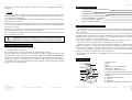
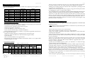
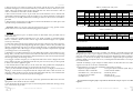
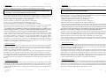
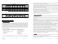
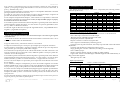
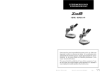
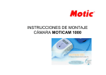
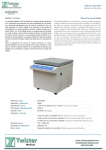
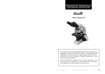
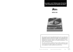
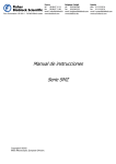
ESTEREOMICROSCOPIOS STEREOMICROSCOPES Serie / Series 200 Este manual es parte inseparable del aparato por lo que debe estar disponible a todos los usuarios del equipo. Le recomendamos leer atentamente el presente manual y seguir rigurosamente los procedimientos de uso para obtener las máximas prestaciones y una mayor duración del mismo. This manual should be available for all users of these equipments. To get the best results and a higher duration of this equipment it is advisable to read carefully this manual and follow the processes of use. Revisión 4 de Marzo-05 Manual de instrucciones 50200XXX Pág. 1 CASTELLANO Gracias por haber adquirido este equipo. Deseamos sinceramente que disfrute del estereoscopio Ura Technic serie 200. Le recomendamos que cuide el equipo conforme a lo expuesto en este manual. Ura Technic desarrolla sus productos según las directrices del marcado CE y haciendo hincapié en la ergonomía y seguridad del usuario. La calidad de los materiales empleados en la fabricación y el correcto proceder le permitirán disfrutar del equipo por muchos años. El uso incorrecto o indebido del equipo puede dar lugar a accidentes, descargas eléctricas, cortocircuitos, fuegos, lesiones, etc. Lea el punto de Mantenimiento, donde se recogen aspectos de seguridad. LEA DETALLADAMENTE ESTE MANUAL DE INSTRUCCIONES ANTES DE OPERAR CON ESTE EQUIPO CON EL FIN DE OBTENER LAS MÁXIMAS PRESTACIONES Y UNA MAYOR DURACIÓN DEL MISMO. Tenga especialmente presente lo siguiente: Este manual es parte inseparable del estereoscopio Ura Technic serie 200, por lo que debe estar disponible para todos los usuarios del equipo. ENGLISH ANNEX I: CE CERTIFICATE AUXILAB S.L. CE DECLARATION OF CONFORMITY STEREOMICROSCOPES SERIES 200 of AUXILAB, S.L. for the Directive of Machines (89/392/CEE modified) and the regulations adopted for their transposition. NAME OF THE MANUFACTURER/IMPORTER: AUXILAB, S.L. ADDRESS: Polígono Morea Norte, 8 31191 Beriáin (Navarra) Debe manipularse siempre con cuidado evitando los movimientos bruscos, golpes, caídas de objetos pesados o punzantes; evitar el derrame de líquidos en su interior Nunca desmonte el equipo para repararlo usted mismo, además de perder la garantía podría producir un funcionamiento deficiente de todo el equipo, así como daños a las personas que lo manipulan. Para prevenir fuego o descargas eléctricas, evite los ambientes secos y polvorientos. Si esto ocurre, desenchufar inmediatamente el equipo de la toma de corriente. Cualquier duda puede ser aclarada por su distribuidor (instalación, puesta en marcha, funcionamiento). Usted puede también mandarnos sus dudas o sugerencias a la siguiente dirección de correo del Servicio Técnico Ura Technic ([email protected]) o bien llamando al Tel: 807117040 (0,30Euros/min). Este equipo está amparado por la Ley de garantías y bienes de consumo (10/2003). No se consideran en garantía las revisiones del equipo. La manipulación del equipo por personal no autorizado provocará la pérdida total de la garantía. Los fusibles (0,5A) o accesorios, así como la pérdida de los mismos, no están cubiertos por dicha garantía. Tampoco estarán cubiertos por el periodo de garantía las piezas en su desgaste por uso natural. Asegúrese de guardar la factura de compra para tener derecho de reclamación o prestación de la garantía. En caso de enviar el equipo al Servicio Técnico adjuntar factura o copia de la misma como documento de garantía. Rellene y envíe la garantía antes de los 15 días después de la compra. El fabricante se reserva los derechos a posibles modificaciones y mejoras sobre este manual y equipo. WE STATE THAT: URA TECHNIC STEREOMICROSCOPES SERIES 200 CODES 50200142, 50200141, 50200162, 50200161, 50200182, 50200181, 50200192, 50200191, 50220182 AND 50200201 Are designed and manufactured according to: Directive 89/392/CEE, including the modifications and the national regulations that transpose them. Directive 73/23/CEE modified over the electric security. Directive 89/336/CEE modified over the electromagnetic compatibility. And that the following harmonized rules have been applied (or part of them): UNE 292-1, UNE 292-2, UNE 292-2/A1, UNE 614-1, UNE 1050, UNE 294, UNE 894-1, UNE 894-2, UNE 60204, UNE 61010-1. BERIAIN 7th July 2004 ¡ATENCIÓN! NO SE ADMITIRA NINGUN APARATO PARA REPARAR QUE NO ESTE DEBIDAMENTE LIMPIO Y DESINFECTADO. Signed by: ALFONSO AINCIBURU SANZ DIRECTOR/MANAGER INDICE DE IDIOMAS Castellano Inglés Pág. 2 2-10 11-19 Manual de instrucciones 50200XXX Revisión 4 de Marzo-05 Polígono Morea Norte, 8 31191 Beriain (Navarra) - Spain. Tel. 948 310 513 Fax 948 312 071 Internet: www.auxilab.es · Email: [email protected] Version 4 March-05 Instruction manual 50200XXX Page 19 ENGLISH return it for overhaul or just to keep it in a safe place when it is not going to be used for a long time. CASTELLANO INDICE DE CONTENIDOS 1. APLICACIONES DEL INSTRUMENTO 2. DESCRIPCIÓN 3. ESPECIFICACIONES TÉCNICAS 4. INSTALACIÓN / PUESTA EN MARCHA 5. MANTENIMIENTO Y LIMPIEZA 6. CAUSAS DE MALA IMAGEN ANEXO I: CERTIFICADO CE Cleaning Never use scourers or substances that can grate for cleaning metallic parts such as stainless steel, aluminium, coatings, etc. as they damage the stereomicroscope and produce an early ageing of the equipment. Use a fluff-free cloth dampened with soaped water that does not contain abrasives for cleaning the stereomicroscope. Lenses must never be dismantled by the user. In case there is any dirt on the external parts of the lenses, you should clean it with a smooth piece of cloth, fluff-free, dampened with a bit of xylol or toluene. Blow the dust laid down on the lenses with a plastic bulb or clean it either with a soft brush made of natural hair or any special gauze for lenses. For cleaning the mechanical parts you should use non-corrosive lubricants, being careful not to touch the optical parts. ATTENTION!! IF EQUIPMENTS ARE NOT PROPERLY CLEAN AND DISINFECTED THEY WOULD NOT BE ALLOWED TO REPAIR BY OUR TECHNICAL SERVICE. 6. CAUSES OF A DEFECTIVE IMAGE In case of a defective image you should check: The illumination is well made. The candle power is not too weak; if so you should change the lamp. The cleanliness of the accessible parts of the optical system, by turning the eyepieces and checking that the specks move; if so you should clean them. You should never dismantle the head, but you can clean it with delicacy by blowing with a plastic bulb with brush the available parts. If you have an optional objective and the parasite images turn when turning it, you should clean it with a dry brush to remove the dust while you look at it with a magnifying glass or an inverted eyepiece. 1. APLICACIONES DEL INSTRUMENTO Los estéreomicroscopios sirven para observar imágenes ampliadas de pequeños objetos, siendo la imagen creada estereoscópica, no invertida y conservando el color original del objeto observado. Las posibles aplicaciones de un estereomicroscopio son prácticamente infinitas y se extienden desde la enseñanza básica hasta la industria electrónica, pasando por todas las actividades en las que se desee ver un objeto con una gran ampliación pero conservando su visión estereoscópica, es decir, tridimensional. Como aplicaciones de los estéreomicroscopios destacamos los diferentes campos: - Enseñanza: básica, secundaria, formación profesional y universitaria. - Industria: electrónica, relojera, textil, joyería, pintura, alimentación, utillaje, fundición, gráfica, galvanizado, etc.; en todo proceso de inspección, montaje y reparación de instrumentos, placas medidoras y otras piezas de precisión, así como en control de calidad. - Agricultura y ganadería, biología, protésicos dentales, restauración artística, filatelia, micología, grafología, mineralogía, óptica, investigación etc. Estos equipos ofrecen una gran comodidad en su uso y una excelente calidad de la imagen observada. 2. DESCRIPCIÓN 9 10 8 11 7 6 5 12 13 4 3 2 Page 18 Instruction manual 50200XXX Version 4 March-05 3 3 4 5 8 9 10 1 Revisión 4 de Marzo-05 1. Pinzas sujeción 2. Platina 3. Base 4. Interruptor encendido/apagado 5. Iluminación incidente 6. Mando de control de enfoque 7. Mando de ajuste de altura cuerpo binocular 8. Anillo de ajuste de tension de enfoque 9. Oculares 10. Mando de ajuste dióptrico 11. Cabezal 12. Objetivo/s 13. Iluminación incidente y transmitida Manual de instrucciones 50200XXX Pág. 3 CASTELLANO 3. ESPECIFICACIONES TÉCNICAS La serie 200 de estereomicroscopios Ura Technic está compuesta por las siguientes versiones con características: Modelo 210 214/1 214/2 216/1 216/2 218/1 218/2 219/1 219/2 220 201 Objetivos 2X 2X 2X 2X 2X 2X, 4X 2X, 4X 2X, 4X 2X, 4X 2X, 4X 2X Ocular WF 10X WF 10X WF 10X WF 10X WF 10X WF 10X WF 10X WF 10X WF 10X WF 10X WF 10X Iluminación Inc. Trans. Recto Si No Si Si No Si Si Si Si Si No No Si Si No Si No No Si Si No Si No No Si Si No Si Si No Si No No Cabezal Incl. 45º Girat. 360 º No No No No No No Si No Si No Si No Si No Si Si Si Si Si Si Si No Otras características (según modelo) - Base: metálica, muy estable, contiene en su interior el transformador para la iluminación. - Par de pinzas: en la base, para sujetar la muestra. - Cuerpo binocular: ajustable en altura sobre el soporte. - Distancia interpupilar: ajustable 30º. - Corrección dióptrica: ± 5 mm en un tubo ocular. - Par de oculares: estándar (10x), con sistema de fijación. - Sistema de enfoque: por piñón y cremallera, con parada de seguridad al final del recorrido y regulación de tensión. - Mandos de enfoque: bilaterales con dispositivo de control de fricción. - Platina: de vidrio esmerilado de 95 mm de diámetro (Según modelo). - Par de anteojeras. - Selector de intensidad de la luz: según modelo. - Interruptor de luz: selector de luz incidente, transmitida o ambas a la vez, según modelo. - Lámpara halógena 12 V 10W. Especificaciones ópticas - Tabla 1, modelos 214 y 216 OCULARES 10X 15X OBJETIVOS Aum. Ø Aum. Ø Aum. Ø campo campo campo 1X 5X 22 mm 10X 20 mm 15X 15 mm 2X 10X 12 mm 20X 10 mm 30X 7,5 mm 3X 15X 8 mm 30X 6,7 mm 45X 5 mm 4X 20X 6 mm 40X 5 mm 60X 3,7 mm 6X 30X 4 mm 60X 3,3 mm 90X 2,5 mm 5X 20X Aum. Ø campo 20X 10 mm 40X 6,5 mm 60X 4,3 mm 80X 3,2 mm 120X 1,8 mm Distancia Trabajo 57 mm 80 mm 61 mm 57 mm 66 mm Aum F Aumentos Pág. 4 ENGLISH Do not place the stereomicroscope near any warm supply (burners, blowlamps, etc), Manual de instrucciones 50200XXX Revisión 4 de Marzo-05 nor expose it directly to the sun. Avoid vibrations, dust and dry environments. During its functioning dangerous materials such as flammable or pathological substances must be out of the safety area. When you are not using the stereomicroscope for a long period of time please make sure it is unplugged in order to avoid possible accidents. It is essential to have the equipment switched off and unplugged from the net before cleaning, checking components or replacing any piece (e.g. replacement of a fuse). Never try to repair the stereomicroscope by yourself, since you will lose the warranty and may provoke damages to the general operating system or the electrical installation, as well as injuries to the people that usually handle the equipment (burns, hurts…). Made under the European regulations for electrical security, electromagnetic compatibility and security on machines. 5. MAINTENANCE AND CLEANING To get the best results and a higher duration of this equipment it is essential to follow the processes of use. Note: All the processes of use mentioned below will not have any value unless you keep a continued and careful maintenance. Please follow the processes of use of this manual. This manual should be available for all users of this equipment. Always use original components and supplies. Other devices can be similar but they can damage the equipment. The stereomicroscope is supplied with a Schuko standard wire. It has to be plugged to an earth connection and the socket should be handy and ready to unplug the equipment in case of emergency. Never try to repair the stereomicroscope by yourself, since you will lose the warranty and may provoke damages to the general operating system or the electrical installation, as well as injuries to the people that usually handle the equipment (burns, hurts…) or damages in nearby equipments. In the event of breakdown please contact your distributor to overhaul through Ura Technic Technical Assistance Department. If the are lamps blown you should replace them by another original Ura Technic ones of 12V10W, being careful not to touch them with the naked hands. Do not use any lamp with higher power, as this could provoke overheating or any other malfunction. Were it essential to replace the fuse (0,5A), you should change it as follows: unscrew the protective lid (FUSE) that you will find at the rear part of the base, replace the fuse locating the new one at the same position and screw it again once you have finished. Do please always use the plastic cover whenever the stereomicroscope is not being used to avoid dust on the optical parts. Please keep the original packaging so as to use it in transport, whenever you have to Version 4 March-05 Instruction manual 50200XXX Page 17 ENGLISH CASTELLANO The horizontal arm is similar in shape to the vertical rod; the first one is placed on the bosshead and tightly screwed with an Allen key of number 2 with two little screws provided. Then you should couple the first ring with the wire. On its end it has a hole in order to assemble an extension to make it flexible. This extension includes a screw to put in the arm's hole and then screw it with the nut with handle without forgetting to put the washers to get a better fastening. At the end of this extension you should put the head, fastening it with two Allen screws of number 2 provided. The illuminator is placed in a circular hole located on the head that is a black piece with cylindrical shape with different widths. Important: When you are not using the stereomicroscope for a long period of time, please make sure it is disconnected and unplugged from the net. Setting up Plug the stereomicroscope to an intake current of 220V 50Hz ±10% provided with an earth connection. Turn on the most suitable illumination for your needs, incident or transmitted light. There is available a black & white contrast stage with transmitted light as an optional accessory, if necessary. Centre the sample into the stage and move the focusing control slowly until you manage to see a sharp image observing through the left eyepiece, which is not provided with dioptric compensation ring. Once you have focused the image you should look through the right eyepiece and, if the image is not neat enough, turn the compensation ring until you manage to have a focused image. With the tool provided (Allen key) you can adjust the focusing control tension to your liking. Thus, you only have to insert an end into the little holes located on the focusing control, maintain the control motionless and turn the key in order to increase/decrease the friction opposed by the focusing control. For bigger or thicker samples you can adjust the binocular section's height above the base's stand. To do this, you should loosen the rear part screw and, once you have placed it where you need to, tighten it again. You should observe with both eyes at the same time and graduate the interpupillary distance until the separate images you see become one stereoscopic vision. Once you have finished working with the stereomicroscope we highly recommend to unplug it, as the electrical components that the adapter has make a little electrical consumption, which produces an early ageing of the equipment and may cause accidents due to heating, as well as an unnecessary waste of energy, etc. Security The stereomicroscope must be used by previously qualified staff that knows how the equipment works thanks to the user manual. You should put the stereomicroscope in a horizontal plane stable table, having a safety area of at least 30 cm per side. Page 16 Instruction manual 50200XXX Version 4 March-05 - Tabla 2, modelos 218, 219 y 220 OCULARES 10X 15X OBJETIVOS Aum. Ø Aum. Ø Aum. Ø campo campo campo 1X 5X 11 mm 10X 20 mm 15X 15 mm 2X 10X 11 mm 20X 10 mm 30X 7,5 mm 1X 5X 22 mm 10X 20 mm 15X 15 mm 3X 15X 8 mm 30X 6,7 mm 45X 5 mm 4X 10X 11 mm 20X 10 mm 30X 7,5 mm 6X 20X 5,6 mm 40X 5 mm 60X 3,7 mm 5X 20X Aum. 20X 40X 20X 60X 40X 80X Ø campo 10 mm 6,5 mm 10 mm 4,3 mm 6,5 mm 3,2 mm Distancia Trabajo 57 mm 57 mm 57 mm 57 mm 57 mm 57 mm Aum F Aumentos - Tabla 3, modelo 201 OCULARES 10X 15X OBJETIVOS Aum. Ø Aum. Ø Aum. Ø campo campo campo 2X 10X 10 mm 20X 10 mm 30X 7,5 mm 5X 20X Aum. 40X Ø campo 6,5 mm Distancia Trabajo 113 mm Aum F Aumentos 4. INSTALACIÓN / PUESTA EN MARCHA Inspección preliminar Desembale el estereomicroscopio, sacándolo con cuidado y prestando especial atención de agarrarlo por la base o por el soporte y nunca por el cabezal ni por los mandos de enfoque, para evitar que sufran los engranajes de precisión del enfoque. Retire el plástico que lo envuelve y, sin conectar el equipo a la red eléctrica, asegúrese de que no presenta ningún daño debido al transporte. De ser así, comuníquelo inmediatamente a su transportista o suministrador. Guarde el embalaje, ya que siempre se deben realizar las devoluciones en su embalaje original con todos los accesorios suministrados. Compruebe los accesorios que usted debe recibir junto al equipo: - Objetivos (según modelo) - Llave para ajustar la tensión (mod. 220 y 214) - Platina de vidrio esmerilado - Cable estándar Schuko - 2 Bombillas 12v y 10w (mod. 214) - Funda de plástico - 2 Lámparas de recambio - Manual de uso - 2 Fusibles 0,5 A. - Certificado de garantía No aceptaremos ningún equipo en periodo de devolución sin que vaya en su embalaje original. Revisión 4 de Marzo-05 Manual de instrucciones 50200XXX Pág. 5 CASTELLANO ENGLISH Instalación Antes de comenzar a utilizar el instrumento, es conveniente familiarizarse con sus componentes y fundamentos básicos, así como con las funciones de sus controles. Installation Before using this instrument, it is convenient for you to familiarize with its components and basic essentials. LEA DETALLADAMENTE ESTE MANUAL DE INSTRUCCIONES ANTES DE OPERAR CON ESTE EQUIPO CON EL FIN DE OBTENER LAS MÁXIMAS PRESTACIONES Y UNA MAYOR DURACIÓN DEL MISMO. PLEASE READ THOROUGHLY THE INSTRUCTIONS BEFORE CONNECTING AND OPERATING WITH THIS EQUIPMENT. Coloque el estereomicroscopio sobre una mesa horizontal, plana y estable, creando un espacio libre al menos de 30 cm por cada lado. No coloque el equipo en zonas próximas a fuentes de calor (mecheros, sopletes...), ni lo exponga directamente a la luz del sol, etc. Retire el papel y las gomas que lo protegen del polvo. Retire también la tapa protectora del objetivo (modelo 220). Evite en el lugar de trabajo productos inflamables o tóxicos. El estereomicroscopio se suministra con un cable Schuko estándar. Inserte el cable de alimentación de corriente alterna (CA) a la base de corriente 220V 50Hz ±10% provista de toma de tierra y por el otro extremo al conector del equipo. Ni el fabricante ni el distribuidor asumirán responsabilidad alguna por los daños ocasionados al equipo, instalaciones o lesiones sufridas a personas debido a la inobservancia del correcto procedimiento de conexión eléctrica. La tensión debe ser de 220V 50Hz ±10%. Con el estereomicroscopio ha recibido un par de oculares (normalmente 10x, según modelo). Dichos oculares están sujetos mediante un tornillo al tubo, para evitar su pérdida. Si desea cambiar los oculares por otros que están disponibles como opción, deberá antes aflojar dicho tornillo y sustituirlos. Vuelva a apretarlo una vez sustituido el ocular. Cuando no vaya a hacer uso del estereomicroscopio durante largos períodos de tiempo, asegúrese de que esté desconectado de la red y protéjalo del polvo (evitando así posibles accidentes y prolongando la vida útil del equipo). Cambio de objetivos Para cambiar el objetivo de los modelos 214 y 216 primero hay que soltar dos pequeños tornillos que tiene el cabezal, uno en el frente y el otro en el lado izquierdo. Después se desplaza el objetivo hacia la derecha hasta que éste se desencaja. Se coloca el objetivo deseado y se vuelven a apretar los dos tornillos. Para cambiar el objetivo de los modelos 218, 219 y 220 sólo hay que girar la torreta. En el modelo 220, para realizar la observación quite la tapa protectora que lleva el objetivo. El objetivo del modelo 201 se cambia de la misma forma que los modelos 214 y 216 sólo que, en lugar de tener dos tornillos, tiene uno en el lado izquierdo del cabezal. Este modelo viene sin montar. Para instalarlo, lea atentamente las instrucciones que vienen a continuación. Please put the stereomicroscope on top of a horizontal, plane and stable table making a free space at least at 30 cm per side. Do not put the equipment near any warm supply (burners, blowlamps…), nor expose it directly to the sun, etc. Retire the paper and rubber bands that Project it from dust. Retire also the objective protective cap (model 220). Avoid inflammable or toxic substances in the working area. The stereomicroscope is supplied with a Schuko standard wire Please insert the wire that feeds the AC electric current in the base of current 220V 50Hz ±10% provided with earth wire and to the other end to the stereomicroscope connector. Neither the manufacturer nor the distributor will assume any responsibility for the damages produced to the equipment during its installation or damages to persons suffered by the improper use of the electric connection. The tension should be 220V 50Hz ±10%. You have received a pair of eyepieces together with the stereomicroscope (normally 10x, according to the model supplied). These eyepieces are secured to the tube by means of a screw in order to avoid their lost. Were you to replace them for an optional pair, you should loosen the screw first, then replace them and finally screw them again. If you are not using the stereomicroscope for a long period of time please make sure it is disconnected from the net and protected from dust (this way you will avoid accidents and will extend its working-life). Changing the objectives To change the objectives in models 214 and 216, first you have to loosen two little screws the equipment has on the head, one on the front and the other on the left side. Then, you move the objective to the right until it knocks out of its position, put the desired objective and finally you tighten the screws again. To change the objectives of models 218, 219 and 220 you only have to turn the turret. In model 220 you have to take off the protective cap of the objective before start working. The objective of model 201 is changed in the same way as models 214 and 216. The only thing that changes on the process is that this model only has a screw on the left side of the head instead of having two. This equipment is supplied without assembling, so you have to follow the instructions given below to complete its installation. Installation of model 201 Instalación del modelo 201 Este modelo posee una base en la que se encuentran tanto el interruptor de encendido/apagado (on/off) como el enchufe del iluminador. La base posee además una varilla vertical en la que hay dos anillas: una que tiene en su parte interna un surco por el que va alojado el cable del iluminador, y otra que posee un tornillo para ajustar la altura del cuerpo binocular. Pág. 6 Manual de instrucciones 50200XXX Revisión 4 de Marzo-05 This model has a base where are located both the on/off switch and the illuminator plug. It also has a vertical rod with two rings: one of them has an inner furrow where the illuminator wire is, and the other one has a screw to adapt the binocular section's height. You have to put a bosshead on the second ring to hold the horizontal arm; this bosshead is meant to adjust height and turn the binocular section. Version 4 March-05 Instruction manual 50200XXX Page 15 ENGLISH 5X OBJECTIVES Mag. 1X 2X 1X 3X 4X 6X 5X 10X 5X 15X 10X 20X Ø field 11 mm 11 mm 22 mm 8 mm 11 mm 5,6 mm EYEPIECES 10X 15X Mag. Ø Mag. Ø field field 10X 20 mm 15X 15 mm 20X 10 mm 30X 7,5 mm 10X 20 mm 15X 15 mm 30X 6,7 mm 45X 5 mm 20X 10 mm 30X 7,5 mm 40X 5 mm 60X 3,7 mm 20X Mag. 20X 40X 20X 60X 40X 80X Ø Working field Distance 10 mm 57 mm 6,5 mm 57 mm 10 mm 57 mm 4,3 mm 57 mm 6,5 mm 57 mm 3,2 mm 57 mm Mag F Magnifications - Chart 3, model 201 5X OBJECTIVES Mag. 2X 10X Ø field 10 mm EYEPIECES 10X 15X Mag. Ø Mag. Ø field field 20X 10 mm 30X 7,5 mm 20X Mag. 40X Ø Working field Distance 6,5 mm 113 mm Mag F Magnifications 4. INSTALLATION / SETTING UP Preliminary inspection Unwrap the stereomicroscope, carefully taking it out and specially taking care of holding it either by the base or the stand but never by the head nor the focusing controls, to avoid focusing precision gears to suffer. Take off the involving plastic and, without connecting the equipment to the net, make sure that it does not present any damage because of the shipment. In case the stereomicroscope presents any damage tell it immediately to your transport agent or dealer so that they can make the claims in the correct time limit. Please keep the original wrapping; you will always need it for returns enclosed with all the accessories supplied. Please check that all the accessories are enclosed with the equipment: - Objectives (according to model supplied) - Key to adjust the tension - Ground glass stage (models 220 and 214). - 2 lamps 12v and 10w (model 214) - Schuko Standard cable. - 2 spare lamps - Plastic cover. - 2 fuses 0,5 A. - User manual. - Warranty certificate. We will not accept any equipment in return period unless it comes in its original wrapping. Page 14 Instruction manual 50200XXX CASTELLANO Sobre la segunda anilla se coloca una nuez que sujeta el brazo horizontal y se emplea - Chart 2, models 218, 219 and 220 - Version 4 March-05 para regular la altura y girar el cuerpo binocular. El brazo horizontal es de forma similar a la varilla vertical; este se inserta en la nuez y se atornilla fuertemente mediante dos pequeños tornillos con una llave Allen del número 2. Luego se le acopla la primera anilla con el cable. En su extremo posee un orificio que sirve para unir la prolongación que lo hace flexible. Dicha prolongación incluye un tornillo que se introduce en el orificio del brazo y se enrosca con la tuerca con mango, sin olvidarnos de colocar las arandelas para obtener mayor sujeción. En el extremo de la prolongación se coloca el cabezal, que se ajusta también mediante dos tornillos Allen del número 2. El iluminador se inserta en un orificio circular que posee el cabezal, que es una pieza de color negro en forma de cilindro con distintas anchuras. Importante: Cuando no vaya a hacer uso del estereo microscopio durante largos periodos de tiempo asegúrese de que está desconectado de la red. Puesta en funcionamiento Conecte correctamente el estereomicroscopio a un enchufe de 220V 50Hz ±10%, provisto de toma de tierra. Conecte el tipo de iluminación, incidente o reflejada, más conveniente a su observación. Opcionalmente existe una platina de contraste blanca /negra para uso con luz reflejada, si fuese necesario. Centre la muestra en la platina y gire el mando de enfoque lentamente hasta conseguir una imagen nítida, observando por el ocular izquierdo no provisto de anillo de ajuste de dioptrías. Una vez enfocado mire por el ocular derecho y, si la imagen no es clara, gire el anillo de ajuste de dioptrías hasta conseguir un buen enfoque. Con la herramienta que se suministra (llave Allen) puede ajustar a su gusto la tensión del mando de enfoque. Para ello solo ha de introducir un extremo en los pequeños orificios que se encuentran en el eje del mando de enfoque, mantener el mando inmóvil y girar la llave para aumentar o disminuir la fricción que opone el mando de enfoque. Para muestras grandes o de mayor grosor puede ajustarse la altura del cuerpo binocular sobre el soporte de la base. Para ello, suelte el tornillo de la parte de atrás y, una vez colocado a la altura necesaria, vuelva a fijarlo fuertemente. Observe por ambos ojos a la vez y gradúe la distancia interpupilar hasta que las imágenes de ambos ojos se fundan correctamente en una sola visión estereoscópica. Una vez acabado el trabajo aconsejamos desenchufar el equipo, puesto que los componentes eléctricos que lleva el adaptador tienen un pequeño consumo eléctrico que implica el envejecimiento prematuro del equipo, posibles accidentes debido a la producción de calor, así como un gasto innecesario de energía, etc. Seguridad El estereomicroscopio debe ser utilizado por personal cualificado previamente, que conozca el equipo y su manejo mediante el manual de uso. Coloque el equipo sobre una mesa horizontal, plana y estable, creando un espacio libre al menos de 30 cm por cada lado. Revisión 4 de Marzo-05 Manual de instrucciones 50200XXX Pág. 7 CASTELLANO No coloque el estereomicroscopio en zonas próximas a fuentes de calor (mecheros, sopletes...), ni exponga el equipo directamente a la luz del sol. Evite las vibraciones, el polvo y ambientes muy secos. Durante su funcionamiento el material peligroso como líquidos inflamables o material patológico, deben estar fuera de esta área. Cuando no vaya a hacer uso del equipo por largos períodos de tiempo, asegúrese de que está desconectado de la red para evitar posibles accidentes. Para cualquier manipulación de limpieza, verificación de los componentes o sustitución de cualquier componente (ej: sustitución de fusible) es imprescindible apagar el equipo y desconectarlo de la toma de corriente. No intente repararlo usted mismo; además de perder la garantía puede causar daños en el funcionamiento general del equipo, así como lesiones a la persona (quemaduras, heridas...) y daños a la instalación eléctrica. Fabricado según las directivas europeas de seguridad eléctrica, compatibilidad electromagnética y seguridad en maquinas. 5. MANTENIMIENTO Y LIMPIEZA Para un adecuado funcionamiento del estereomicroscopio es necesario seguir algunas recomendaciones. Nota: Todas las normas de utilización citadas anteriormente carecerán de valor si no se realiza una continua labor de mantenimiento. Siga las instrucciones y advertencias relativas a este manual. Tenga este manual siempre a mano para que cualquier persona pueda consultarlo. Utilice siempre componentes y repuestos originales. Puede ser que otros dispositivos sean parecidos, pero su empleo puede dañar el equipo. El estereomicroscopio dispone de un cable de red Schuko; este debe conectarse a una toma de corriente que esté conectada a tierra, debiendo quedar a mano para poder desconectarlo en caso de emergencia. No intente repararlo usted mismo; además de perder la garantía puede causar daños en el funcionamiento general del estereomicroscopio, así como lesiones a la persona (quemaduras, heridas...) y daños a la instalación eléctrica, o equipos eléctricos cercanos. En caso de avería diríjase a su proveedor para la reparación través del Servicio Técnico de Ura Technic. Si se funden las lámparas reemplácelas por otras de 12V10W originales Ura Technic teniendo cuidado de no tocar la ampolla con las manos desnudas. No utilice lámparas de mayor potencia, ya que podría producir un sobrecalentamiento u otra mala función. Si fuese necesario remplazar el fusible (0.5A) hágalo según el siguiente procedimiento: desenrosque la tapa protectora (FUSE) que encontrará en la parte de atrás de la base, reemplace el fusible y vuelva a colocarlo en la misma posición, enroscando de nuevo la tapa protectora. Utilice la funda de plástico siempre que el estereomicroscopio no esté en uso para evitar que el polvo se pose sobre las partes ópticas. Pág. 8 Manual de instrucciones 50200XXX Revisión 4 de Marzo-05 ENGLISH 3. TECHNICAL SPECIFICATIONS Ura Technic stereomicroscope's series 200 is composed by the following models and technical specifications: Model 210 214/1 214/2 216/1 216/2 218/1 218/2 219/1 219/2 220 201 Objectives 2X 2X 2X 2X 2X 2X, 4X 2X, 4X 2X, 4X 2X, 4X 2X, 4X 2X Eyepiece WF 10X WF 10X WF 10X WF 10X WF 10X WF 10X WF 10X WF 10X WF 10X WF 10X WF 10X Lighting Head Incid. Transm. Straight Inclined 45º Rotary 360º Yes No Yes No No Yes No Yes No No Yes Yes Yes No No Yes No No Yes No Yes Yes No Yes No Yes No No Yes No Yes Yes No Yes No Yes No No Yes Yes Yes Yes No Yes Yes Yes Yes No Yes Yes Yes No No Yes No Other features (depending on the model supplied) - Base: metallic and very stable, it contains the transformer for the illumination. - Pair of slide clips: on the base to hold the simple. - Binocular section: adjustable in height on the stand. - Interpupillary distance: adjustable 30º. - Diopter correction: ± 5 mm in an eyepiece tube. - Pair of eyepieces: standard (10x), with fixing system. - Focusing system: by pinion and rack, with safety stop at the end of the route and tension adjustment. - Focusing controls: bilateral, with friction control system. - Stage: ground glass of 95 mm of diameter (according to model supplied). - Pair of rubber eyecups. - Knob to select the intensity of light: according to model supplied. - Light switch: selector for incident light, transmitted light or both simultaneously according to the model supplied. - Halogen lamp 12 V 10W. Optical specifications - Chart 1, models 214 and 216 EYEPIECES 10X 15X OBJECTIVES Mag. Ø Mag. Ø Mag. Ø field field field 1X 5X 22 mm 10X 20 mm 15X 15 mm 2X 10X 12 mm 20X 10 mm 30X 7,5 mm 3X 15X 8 mm 30X 6,7 mm 45X 5 mm 4X 20X 6 mm 40X 5 mm 60X 3,7 mm 6X 30X 4 mm 60X 3,3 mm 90X 2,5 mm 5X 20X Mag. Ø field 20X 10 mm 40X 6,5 mm 60X 4,3 mm 80X 3,2 mm 120X 1,8 mm Mag F Magnifications Version 4 March-05 Instruction manual 50200XXX Page 13 Working Distance 57 mm 80 mm 61 mm 57 mm 66 mm ENGLISH INDEX OF CONTENTS 1. USES OF THE INSTRUMENT 2. DESCRIPTION 3. TECHNICAL SPECIFICATIONS 4. INSTALLATION / SETTING UP 5. MAINTENANCE AND CLEANING 6. CAUSES OF A DEFECTIVE IMAGE ANNEX I: CE CERTIFICATE 12 12 13 14 17 18 19 1. USES OF THE INSTRUMENT Stereomicroscopes are used to observe enlarged images of little objects, being the image you see through it a stereoscopic one, not inverted and preserving the object's original colour. As a result of this, they can be used in a wide range of fields going from education to electronic industry, passing through every single activity that needs an object to be seen enlarged but maintaining a stereoscopic (three-dimensional) vision. We stand out some field where stereomicroscopes can be used: - Education: primary, secondary, vocational training and university. - Industry: electronics, clock making, textile, jewellery, painting, food industry, tool setup, casting (metallurgy), graphics, galvanising, etc. In every process of inspection, assembly and repairing of instruments, measuring plates or any other kind of precision piece, as well as in quality control processes. - Agriculture and stockbreeding, biology, prosthodontists, artistic restoration, philately, mycology, graphology, mineralogy, optics, research, etc. These equipments provide a great comfort in their use and an excellent quality of the observed image. 2. DESCRIPTION 9 10 8 11 7 6 5 12 13 4 3 2 1 Page 12 CASTELLANO Guarde el embalaje original para transportarlo, así como para cuando no vaya a utilizar 1. Holding clips 2. Stage 3. Base 4. On/off switch 5. Incident light 6. Focusing control knob 7. Height adjustment knob for binocular section 8. Focusing tension adjustment ring 9. Eyepieces 10. Dioptric adjustment ring 11. Head 12. Objective/s 13. Incident and transmitted light Instruction manual 50200XXX Version 4 March-05 el equipo durante mucho tiempo o cuando haya que enviarlo a revisar. Limpieza Para la limpieza de las partes metálicas, acero inoxidable, aluminio, pinturas, etc nunca utilice estropajos o productos que puedan rallar, ya que deterioran el estereomicroscopio, limitando la vida útil del equipo. Para la limpieza del equipo recomendamos se utilice un trapo libre de pelusa humedecido con agua jabonosa que no contenga productos abrasivos. Las lentes no deben ser desmontadas nunca por el usuario. Si hubiese cualquier suciedad en las superficies externas de las lentes, límpielas con un paño suave que no desprenda pelusa humedecido con un poco de xilol o tolueno. Para quitar el polvo que se haya posado sobre las lentes sople con una pera o límpielo con un cepillo o pincel suave de pelo natural, o mediante alguna gasa especial para lentes. En las partes mecánicas utilice lubricantes no corrosivos, teniendo especial cuidado de no tocar las partes ópticas. ¡ATENCIÓN! NO SE ADMITIRA NINGUN APARATO PARA REPARAR QUE NO ESTE DEBIDAMENTE LIMPIO Y DESINFECTADO. 6. CAUSAS DE UNA MALA IMAGEN En caso de una imagen deficiente comprobar: Que la iluminación esté bien realizada. Que la intensidad lumínica no sea demasiado débil; si es así se debe cambiar la lámpara. La limpieza de las partes accesibles del sistema óptico, haciendo girar los oculares contemplando si las motitas se mueven; si es así límpielos. Nunca debe desmontar el cabezal, pero sí puede limpiarlo delicadamente, soplando con una pera con pincel aquellas superficies accesibles. Si dispone de objetivo opcional y las imágenes parásitas giran al girarlo, límpielo con la ayuda de un pincel seco intentando eliminar el polvo, observando la superficie frontal con una lupa o con un ocular invertido. Revisión 4 de Marzo-05 Manual de instrucciones 50200XXX Pág. 9 CASTELLANO ANEXO I: CERTIFICADO CE AUXILAB S.L. DECLARACIÓN CE DE CONFORMIDAD ESTEREOMICROSCOPIOS SERIE 200 de Auxilab, S.L a la Directiva de Máquinas (89/392/CEE modificada) y a las reglamentaciones adoptadas para su transposición. NOMBRE DEL FABRICANTE / IMPORTADOR: AUXILAB, S.L. DIRECCIÓN: ENGLISH Thank you for choosing this equipment. We sincerely wish that you enjoy your stereomicroscope Ura Technic series 200. We highly recommend looking after this equipment according to what is stated in this manual. Ura Technic develops its products according to the CE marking regulations as well as emphasizing the ergonomics and security for its user. The correct using of the equipment and its good quality will permit you to enjoy this equipment for years. The improper use of the equipment can cause accidents and electric discharges, circuit breakers, fires, damages, etc. Please read the point of Maintenance, where we expose the security notes. TO GET THE BEST RESULTS AND A HIGHER DURATION OF THE EQUIPMENT IT IS ADVISABLE TO READ THOROUGHLY THIS MANUAL BEFORE OPERATING WITH THE EQUIPMENT. Please bear in mind the following: This manual is inseparable from the stereomicroscope Ura Technic series 200, so it Polígono Morea Norte, 8 31191 Beriáin (Navarra) should be available for all the users of this equipment. You should carefully handle the stereomicroscope avoiding sudden movements, knocks, free fall of heavy / sharp objects on it. Avoid spilling liquids inside the equipment. Never dismantle the different pieces of the stereomicroscope to repair it yourself, since DECLARAMOS QUE: ESTEREOMICROSCOPIOS URA TECHNIC SERIE 200 REFERENCIAS 50200142, 50200141, 50200162, 50200161, 50200182, 50200181, 50200192, 50200191, 50220182 Y 50200201 Esta diseñado y fabricado de acuerdo a: Directiva 89/392/CEE, incluidas las modificaciones de la misma, y las reglamentaciones nacionales que la transponen. Directiva 89/336/CEE modificada sobre compatibilidad electromagnética. Directiva 73/23/CEE modificada sobre seguridad eléctrica. Y que se han aplicado las siguientes normas armonizadas (o parte de ellas): UNE 292-1, UNE 292-2, UNE 292-2/A1, UNE 614-1, UNE 1050, UNE 294, UNE 894-1, UNE 894-2, UNE 60204, UNE 61010-1 BERIAIN a 7 de Julio de 2004 it could produce a defective use of the whole equipment and a loss of the product warranty, as well as injuries on people that handle the equipment. To prevent fire or electric discharges avoid dry or dusty environments. In case it may happen unplug the equipment immediately. If you have any doubt about setting up, installation or functioning do not hesitate in contacting your wholesaler. You can also tell us any doubts or suggestions you have by contacting Ura Technic Technical Assistance Department by email to [email protected] or by telephone: +34 807 117 040 (0,30 Euros/min). This equipment is protected under the Warranties and consumer goods regulation (10/2003). Overhaul is not covered by the stereomicroscope warranty. Operations made by non-qualified staff will automatically produce a loss of the stereomicroscope warranty. Neither fuses (0,5A) nor accessories (including their loss), are covered by the product's warranty. The warranty neither covers piece's deterioration due to the course of time. Please make sure you keep the invoice, either for having the right to claim or asking for warranty coverage. In case you have to send the equipment to Ura Technic Technical Assistance Department you should enclose the original invoice or a copy as guarantee. Please do not forget filling the warranty certificate and send it before 15 days after the date of purchase. Manufacturer reserves the right to modify or improve the manual or equipment. ATTENTION!! IF EQUIPMENTS ARE NOT PROPERLY CLEAN AND DISINFECTED THEY WOULD NOT BE ALLOWED TO REPAIR BY OUR TECHNICAL SERVICE. Fdo: ALFONSO AINCIBURU SANZ DIRECTOR/GERENTE INDEX OF LANGUAGES Polígono Morea Norte, 8 31191 Beriain (Navarra) - Spain. Tel. 948 310 513 Fax 948 312 071 Internet: www.auxilab.es · Email: [email protected] Pág. 10 Manual de instrucciones 50200XXX Revisión 4 de Marzo-05 2-10 11-19 Spanish English Version 4 March-05 Instruction manual 50200XXX Page 11