1
TAD-30K (GB/ES) 10.10.20 11:39 AM ページ b
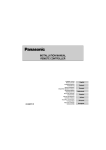
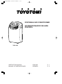
PORTABLE AIR CONDITIONER
ACONDICIONADOR DE AIRE
PORTATIL
TAD-30K
INSTRUCTION MANUAL
MANUAL DE INSTRUCCIONES
ENGLISH
ESPAÑOL
P. 1
P. 5
TAD-30K (GB/ES) 10.10.20 11:39 AM ページ c
A
B
A4
F
PA
G
F1
B7
A1
B1
A5
A2
B2
F2
A6
B3
A3
B4
A7
B5
B6
C
H
C6
C9 C8
C7
C10 C11
C12
C13
C13
C1
C5
C3
C5
C2
C4
C14
C1
C2
C3
C4
C5
!
D
!1
!2
more than
50cm (20 in.)
more than
50cm (20 in.)
E
J
N
1
J3
2
3
J4
4
5
6
7
8
9
1
J5
J1
J2
1
1
TAD-30K (GB/ES) 10.10.20 11:39 AM ページ d
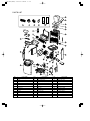
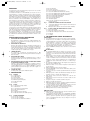
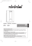
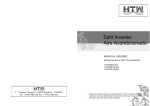
PARTS LIST
25
35
26
27
28
29
33
30
34
32
24
21
11
12
16
20
18
23
15
10
22
9
8
13
14
4
5
17
7
6
3
19
1
2
NO.
PART NAME
NO.
PART NAME
NO.
PART NAME
1
Base pan assembly
13
Capacitor A (Rear FM)
25
Carton
2
Caster
14
Main circuit board
26
Exhaust duct hose
3
Float
15
CapacitorB (Compressor)
27
Exhaust duct hose adapter nozzle
4
Micro switch
16
Indication lamp circuit
28
Exhaust duct hose grille
5
Drain motor
17
Front panel
29
Cover
6
Blade
18
Power supply cord
30
Window panel kit
7
Compressor
19
Drain cap
31
Instruction manual
8
Rear fan motor
20
Rear panel
32
Styrofoam (Bottom)
9
Rear fan
21
Intake air grille
33
Styrofoam (Right)
10
Capacitor C (Front FM)
22
Right side panel
34
Styrofoam (Left)
11
Front fan motor
23
Left side panel
35
Cardboard
12
Front fan
24
Remote control
TAD-30K (GB/ES) 10.10.20 11:39 AM ページ 1
ENGLISH
SUMMARY
C12 Timer set lamp
C13 Digital indicator
C14 C/F toggle button (Remote control)
The idea behind the unit is to provide a localized supply of cool air.
The unit will greatly enhance your personal comfort whether at
a work station or even in your favorite chair.
Four (4) casters enable you to move the unit easily from room
to room. It cools and dries the air at the same time so that you
can stay comfortable even when it's humid or rainy outside.
Also your furnishings and fabrics are kept in good condition
when it's used as dehumidifier.
Conventional air conditioners use large quantities of energy to
cool an entire room, including walls and furniture. This unit
creates a zone of cool and dry air only where it is needed. It
does not waste energy cooling the surroundings.
It's easy to operate. The built-in timer allows from 1 to 12 hours
of operation, which will automatically turn the unit on and off.
This is especially convenient at bedtime.
Venting is not required. However, if the unit is to be used exclusively in one space, the cooling efficiency will be enhanced by
using the venting kit accessory, which is included with the uit.
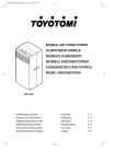
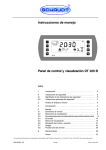
Fig. I
I1
I2
Fig. J
J1
J2
J3
J4
J5
2. SAFETY TIPS
IMPORTANT
¡ Read instructions carefully before operation.
¡ The unit should be operated when the room temperature is
between 18˚C (64˚F) to 35˚C (95˚F). If the room temperature
is below 18˚C (64˚F), ice may form on the coils. If the room
temperature is above 35˚C (95˚F), the compressor will automatically shut off to protect itself.
¡ ALWAYS, wait 3 min. to restart after turning unit off.
WARNING
¡ NEVER expose infants, handicapped persons, or senior
persons directly to the airflow. Adjust the airflow direction.
¡ Keep children away from unit. Children are particularly liable to this danger. The inside fan is running at high
speed. Covering them may deteriorate air conditioner performance or cause it to become inoperative.
¡ NEVER insert objects of any kind into the air intake or air
outlet.
¡ DO NOT unplug if your hands are wet. An electrical shock
may occur.
¡ DO NOT operate in a wet location.
¡ ALWAYS plug into 220 V, 50 Hz, single phase electrical outlet.
¡ Be sure the power plug fits the receptacle securely.
¡ DO NOT run power cord under carpets, rugs, or floor mats
of any kind.
¡ DO NOT attempt to shorten or alter power cord in any way.
¡ DO NOT apply any excessive force or pressure to the power supply cord.
¡ Make sure that the plug is free of dust.
¡ DO NOT use an extension cord.
¡ DO NOT turn on and off by inserting or removing the power plug which may cause electric shock or fire.
¡ If there is a fear of lightning, stop the unit and disconnect
the power supply cord.
¡ DO NOT touch the evaporator, condenser and pipes.
¡ DO NOT operate with filter removed.
OPERATIONAL FEATURES
1.
2.
3.
4.
5.
6.
COOLING OPERATION:
Normally, cool air is directed out the front louvers by the
circulation fan which has three (3) stages of fan speed.
AUTOMATIC OPERATION:
Once the desired function has been set, it is memorized as
long as it remains connected to the wall outlet. In the event
of a power failure, the desired function must be re-entered
when power is restored.
THERMO CONTROL
The compressor will automatically shift to ON or OFF to
maintain the desired temperature.
TIMER OPERATION:
The unit will turn on and off after the designated period of
time (1, 2, 3, ...12 hours).
AUTOMATIC SHUT-OFF MECHANISM WHEN THE
DRAIN TANK IS FULL:
When the drain tank is full, the unit will be automatically
shut off. The warning lamp will light. It is always required
to press the power button twice to resume operation after
the condensed water is removed from the tank.
AIR FILTER:
A pre-filter protects the unit from dust.
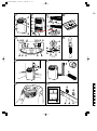
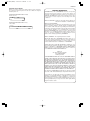
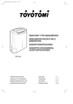
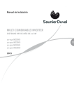
1. DESCRIPTION
Fig. A
A1
A2
A3
A4
A5
A6
A7
Fig. B
B1
B2
B3
B4
B5
B6
B7
Fig. C
C1
C2
C3
C4
C5
C6
C7
C8
C9
C10
C11
EXHAUST DUCT SET
Exhaust duct hose adapter nozzle (2 pcs.)
Exhaust duct hose
WINDOW PANEL KIT
Window panel
Window panel extension
Exhaust duct hose grille
Cover
Screws
FRONT
Air outlet
Vertical louver
Front panel
Operation panel
Carrying handle
Horizontal louver
Caster
¡
¡
REAR
Air intake (Evaporator)
Exhaust outlet
Air intake (Condenser)
Power supply cord
Power plug
Drain water outlet
Air intake grille (Pre-filter)
¡
¡
¡
¡
¡
OPERATION PANEL
Power button
Mode button
Fan speed button
Timer button
Adjust buttons
Warning lamp (Tank full)
Cool mode lamp (green)
Dry mode lamp (orange)
Fan mode lamp (yellow)
Room temp lamp
Set temp lamp
¡
¡
1
CAUTION
Keep unit more than 50 cm (20 in.) away from any objects
or wall. (Fig. D)
If the unit is operated in COOL mode in an area of very
high moisture, the top plate and the rear plate may get
covered with a mist. Wipe off any mist before it has a
chance to get on the floor or rug.
Remove drain water before moving unit.
To minimize corrosion, DO NOT use in damp, salty air
area.
DO NOT operate in direct sunlight.
DO NOT use for such particular purpose as preservation of
foodstuff, animals, plants, precision appliances, arts and
medicine.
DO NOT place an animal, plants or combustion equipment
in a place which is subjected to the direct air flow of the
unit.
DO NOT ride or place the objects on the unit.
DO NOT turn the unit on its side or upside down.
TAD-30K (GB/ES) 10.10.20 11:39 AM ページ 2
ENGLISH
3. OPERATION
3.
4.
5.
OPERATING STEPS:
1. PRESS ''POWER'' BUTTON (C1) TO ''ON''.
Cool mode lamp (C7) and Low lamp are lit at this time and
unit starts.
2. PRESS MODE BUTTON (C2).
Press the mode button (C2) to set your desired operation
mode "COOL" (C7), "DEHUMIDIFY" (C8) or "FAN" (C9).
COOL mode (C7)
During the "COOL" mode the air is cooled and hot air is exhausted to the outside air through the exhaust duct hose.
DRY mode (C8)
Air is dehumidified as it passes through the unit, without
being in full cool mode.
In "DEHUMIDIFY" mode operation, you cannot change the
fan speed.
FAN mode (C9)
The "FAN" mode provides only circulation of room air, so
that you cannot set the room temperature.
3. PRESS TIMER/TEMPERATURE ADJUST BUTTONS (C5)
Set the desired room temperature by pressing UP button
"▲" or DOWN button "▼". The default display is room temperature.
When "▲" or "▼" button is pressed, the set temperature is
displayed and may be adjusted. After 15 seconds the display will revert back to room temperature.
By pressing both buttons at once, the display will toggle
between Celsius and Fahrenheit. When using the remote
control, press the C/F toggle button (C15).
4. PRESS FAN SPEED BUTTON (C3)
Press the fan speed button (C3) to set the desired air flow
rate.
High · · · · · · · · · · · Operation at a high air flow
Med · · · · · · · · · · · Operation at a medium air flow
Low · · · · · · · · · · · Operation at a low air flow
5. AIR DEFLECTION
The vertical louvers (A2) may be set on right and left manually in desired direction. (Fig. E)
6. STOP OPERATION
Press the Power button (C1) and all lights will go out.
5. CLEANING
CLEANING AIR INTAKE GRILLE (Fig. G)
1. Clean the air intake grille (B7) once every two weeks.
2. To remove the air intake grille (B7), pull the grille off.
3. Remove the dust with a vacuum cleaner.
WARNING
¡ DO NOT touch the evaporator. It may cause injury or damage.
CAUTION
DO NOT rinse the charcoal filter with water.
CLEANING SURFACE
Clean the outside of the unit with a soft damp cloth.
¡
¡
At the end of each season, or when you do not plan to use your
unit for an extended period of time, the following procedures
are recommended.
1.
2.
Run the unit 5 or 6 hours with only the ''FAN'' (C9) mode
operating in order to dry the inside.
Remove the drain water from the tank and unplug the unit.
3.
Clean the unit.
Wipe off any dirt or dust on the unit with a soft damp cloth
or a vacuum cleaner, and then wipe again using a soft dry
cloth.
4.
5.
Clean the air intake grille (B7) and replace it.
Store the unit.
The original shipping carton is the best place to store your
unit. If you do not have the original packing materials, cover
the unit with a large plastic bag and store in a cool dry place.
¡
¡
CAUTION
ALWAYS store the unit in the vertical position.
DO NOT put heavy objects on top of the unit.
7. TRANSPORTATION
Preferably keep the unit in the vertical position during transportation. If this is not possible then lay it on its rear side, when
at destination put the unit back in the vertical position and wait
at least ten (10) minutes before using it. Before
transporting/moving the unit make sure the drain tank is empty.
4. DRAINING EXCESS WATER (Fig. F)
2.
CAUTION
NEVER use gasoline, solvents, chemical products or polish
as they could damage the surfaces.
6. LONG-TERM STORAGE
TIMER OPERATION
Auto turning OFF:
With unit in cool mode, press Timer button (C4) to select
number of hours you would like the unit to run in cool
mode until it automatically shuts off.
Auto turning ON:
With unit powered off, press Timer button (C4) to select
number of hours until you would like the unit to automatically start.
USING REMOTE CONTROL
The functions work the same as your air conditioner's operation panel. (Fig. C)
Batteries: Remove the cover on the back of the remote control and insert the batteries with the (+) and (-) poles pointing in the proper direction. (Fig. H)
CAUTION
¡ Use only AAA or IEC R03 1.5V batteries.
¡ DO NOT attempt to recharge the supplied batteries.
¡ All batteries should be replaced at the same time.
¡ DO NOT dispose of the batteries in a fire as they may explode.
¡ DO NOT install the batteries with the polarity (+/-) reversed.
¡ Keep batteries and other things that could be swallowed
away from young children. Contact a doctor immediately if
an object is swallowed.
1.
When the water stops draining out, replace the drain plug.
Remove the pan of water.
Operate the unit in Fan mode to dry the interior of the unit.
NOTE: Remove the drain water from the tank once a week.
Drain excess water from the tank by placing a pan under
the drain water outlet. (Fig. F2)
Remove the drain plug, and let the water drain into the pan.
2
TAD-30K (GB/ES) 10.10.20 11:39 AM ページ 3
ENGLISH
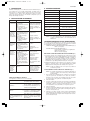
8. TROUBLESHOOTING
SYMPTOM
Unit does
not work.
CAUSE
9. SPECIFICATIONS
SOLUTION
MODEL
- Power cut.
- Wait for power to be
supplied again.
- The plug has been - Plug in again.
plugged improperly.
COOLING CAPACITY
DEHUMIDIFYING CAPACITY
POWER SOURCE
- The full-tank indicator - Remove the drain
is ON. Tank is full.
water from the drain
tank.
POWER CONSUMPTION
OPERATING CURRENT
Unit suddenly stops
during in
operation.
- The indoor tempera- - Reset the temperature has reached the ture level.
set temperature level.
- The preset time is up. - Reset the timer.
- The full-tank indicator - Remove the drain
is ON. Tank is full.
water from the drain
tank.
AIR FLOW (MAX.)
Unit runs in- - Malfunction.
- Contact your dealer.
termittently. - Surrounding temperature is too high or
too low.
- Exhaust duct hose is - Check the duct hose.
blocked.
Unit func- Window or door is
tions but the left open in the room.
room is not - There is heat source
cooled.
in the room or too
many of people in it.
- Air intake grille is
clogged.
- Filter is too dirty.
- Temperature setting
is too high.
Condensed
water is
spilled out
when moving the unit.
1200 W
9.5 A
177 CFM (300 m3/h)
18˚C~35˚C (64˚F~95˚F)
DIMENSIONS (WxHxD)
17-1/8" x 30-1/4" x 17"
(435 x 770 x 430 mm)
66 Lbs. (30 kg)
COMPRESSOR
ROTARY
REFRIGERANT
R-410A
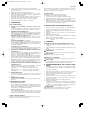
If the unit is to be used exclusively in one space, the cooling efficiency will be enhanced by using the following venting kit accessories.
EXHAUST DUCT SET (FLEXIBLE TUBE) (Fig. I)
Max. 1.2m (4 ft.)
WINDOW PANEL KIT (Fig. J)
For sliding and double-hung
windows
Max. 94cm (37 in.)
Min. 72cm (28-1/4 in.)
USING EXHAUST DUCT SET (Fig. I)
1. Insert both ends of exhaust duct hose (flexible tube) (I2) into exhaust duct hose adapter nozzle (I1) by turning it
counter clockwise onto the tube and fix one of the exhaust
dust hose adapter nozzle (I1) into exhaust outlet (B2) by
turning it clockwise until it locks.
2. Extend the exhaust duct hose (I2) and close the window or
door as far as possible trapping the exhaust duct hose
adapter nozzle (I1).
NOTE: Place the unit as close as possible to the window
or door.
BEFORE CALLING FOR SERVICE
The followings are not defects.
This sound is generated from
A hissing noise or hollow e the refrigerant flowing within
sound :
pipes.
Such odor as tobacco, cosmetics,
e or foods may accumulate in the
unit.
Single Phase 220V, 50Hz
10.VENTING KIT ACCESSORIES
- The tank is nearly full. - Remove the drain
plug on the rear bottom of the unit, drain
off the water then the
unit will be in operation automatically.
Odor :
0.42 gal/h (1.6 L/H)
NOTE: Cooling air capacity will vary according to temperature
and humidity of the room.
- Clean the air intake
grille.
- Replace the filter.
- Lower the temperature setting.
This noise is generated from the
e unit when it is expands or contracts with temperature changes.
3.0 kW (10,000 BTU/H)
OPERATING TEMP. RANGE
WEIGHT
- Close all windows
and door.
- Move out any heat
source in the room.
A squeaking noise :
TAD-30K
USING WINDOW PANEL KIT (Fig. J)
NOTE: Window installations are possible by the use of
the exhaust duct set and window planel kit.
1. Fix the exhaust duct hose grill (J3) to the window panel
with four (4) screws. Make sure that the panel is extended
so that screws do not go into sliding portion of panel.
2. Open the window.
3. Place the window panel in the window, extending it to fit
the width of the window. Once panel is extended, the panel can be locked into this width by tightening the two (2)
screws on the top panel.
4. Close the window.
5. Attach the exhaust duct hose adapter nozzle (I1) on the exhaust duct hose grille (J3).
6. When not in use, the exhaust duct hose adapter nozzle (I1)
may be closed off with the cover for exhaust duct hose
grille (J3) provided.
NOTE: The same procedure can be adapted for vertical
installation in sliding windows.
To prevent overloading the comThe unit does not start nor
change operation mode e pressor motor, the unit will be
stopped for more than 3 minutes.
immediately :
3
TAD-30K (GB/ES) 10.10.20 11:39 AM ページ 4
ENGLISH
OPTIONAL ACCESSORIES
When you need a longer size window panel, please purchase
the extension window panel "B" and use it with the original
window panel "A".
LIMITED WARRANTY
TOYOTOMI CO., LTD. ("TOYOTOMI") warrants each product
and any parts thereof sold by it to be free from defects in
materials or workmanship under normal use and service for
TWELVE (12) MONTHS from the date of delivery to the original purchaser at retail subject to the following terms and
conditions :
EXTENSION WINDOW PANEL "B" (M)
80 cm (31-1/2")
WHAT IS COVERED : Product or any parts thereof which are
defective in materials or workmanship.
EXTENSION WINDOW PANEL "B" (L)
142 cm (56")
WHAT IS NOT COVERED :
This warranty does not extend to any defect due to the negligence of others; failure to install, operate or maintain unit
in accordance with instructions (operating and maintenance
instructions are furnished with each new unit); unreasonable
use, accidents, alteration, use of unauthorized or non-standardized TOYOTOMI parts and accessories; electrical malfunction, i.e., as resulting from large power surges, short circuit, etc.; incorrect installation; or repair by anyone other
than a service facility specified by TOYOTOMI.
WHO IS COVERED : The original purchaser at retail.
WHAT WE WILL DO : TOYOTOMI will either repair or replace, at its option, all defective parts free of charge that are
covered by this limited warranty on a carry-in basis, to your
nearest authorized dealer or distributor of TOYOTOMI.
WHAT YOU MUST DO FOR WARRANTY SERVICE : You
must return the defective Product or part to any authorized
dealer or distributor of TOYOTOMI with this LIMITED WARRANTY. If service is not available locally, please contact our
CUSTOMER RELATIONS DEPARTMENT at :
BBR S.A.
Av. Vitacura 5748, Santiago.
Fono: 600 586 5000
www.toyotomi.cl
THE FOREGOING EXPRESSES ALL OF TOYOTOMI'S OBLIGATIONS AND LIABILITIES WITH RESPECT TO THE QUALITY
OF PRODUCT FURNISHED BY IT. ALL OTHER WARRANTIES,
EXPRESSED OR IMPLIED, INCLUDING THE WARRANTIES
OF MERCHANTABILITY OR FITNESS FOR A PARTICULAR
PURPOSE ARE DISCLAIMED. TOYOTOMI SHALL NOT BE LIABLE FOR THE LOSS OF USE OF THE PRODUCT, INCONVENIENCE, LOSS OR ANY OTHER DAMAGES, DIRECT OR
CONSEQUENTIAL ARISING OUT OF, THE USE OF, OR INABILITY TO USE, THE PRODUCT OR DAMAGES RESULTING
FROM OR ATTRIBUTABLE TO DEFECTS IN THE PRODUCT.
No other than TOYOTOMI has authority to extend or modify
the terms of this Limited Warranty in any manner whatsoever.
Some states do not allow the exclusion or limitation of incidental or consequential damages or limitations on how long
an implied warranty lasts, so these limitations or exclusions
may not apply to you. This Limited Warranty gives you specific legal rights and you may also have other rights which
vary from state to state.
4
TAD-30K (GB/ES) 10.10.20 11:39 AM ページ 5
ESPAÑOL
RESUMEN
C4
C5
C6
C7
C8
C9
C10
C11
C12
C13
C14
La unidad ha sido diseñada para proporcionar un acondicionamiento de aire localizado.
La unidad aumentará su confortabilidad ya sea que esté en su
lugar de trabajo o sentado cómodamente en su sillón preferido.
Cuatro (4) ruedas permiten desplazar fácilmente la unidad de
una habitación a otra. Refrigera y seca el aire simultáneamente
para crear un ambiente confortable aun en los días húmedos y
lluviosos. Utilizado como deshumidifador, esta unidad le ayudará a mantener sus muebles y tapices en buenas condiciones.
Los acondicionadores de aire convencionales consumen gran
cantidad de energía para enfriar una habitación completa, incluyendo las paredes y los muebles. En cambio, la unidad crea
una zona de aire frío y seco sólo donde es necesario. No derrocha energía enfriando los espacios circundantes.
Su operación es muy fácil. El timer incorporado permite ajustar
la unidad para que se active o desactive automáticamente al
cabo de un período de tiempo programable entre 1 a 12 horas.
Esto es especialmente conveniente antes de irse a la cama.
No requiere ventilación. Sin embargo, si va a usar la unidad
exclusivamente en un solo lugar, podrá aumentar la eficiencia
de enfriamiento utilizando el kit para ventana ofrecido como
accesorio.
Fig. I
I1
I2
Fig. J
J1
J2
J3
J4
J5
2.
3.
4.
5.
6.
IMPORTANTE
¡ Lea atentamente las instrucciones antes de usar la unidad.
¡ Haga funcionar la unidad a una temperatura ambiente
comprendida entre 18˚C (64˚F) y 35˚C (95˚F). Si la temperatura ambiente es inferior a 18˚C (64˚F) se podrá formar
hielo sobre los serpentines. Si la temperatura ambiente
está por encima de 35˚C (95˚F), el compresor se desactivará automáticamente para fines de autoprotección.
¡ Espere SIEMPRE 3 minutos antes de volver a encender la
unidad.
OPERACION DE ENFRIAMIENTO:
Normalmente el aire frío sale por las rejillas delanteras impulsado por el ventilador de circulación que tiene tres (3)
etapas de velocidad.
OPERACION AUTOMATICA:
Después de ajustar a la función deseada, permanecerá en
la memoria mientras la unidad se encuentre enchufada al
tomacorriente mural. Si ocurre una interrupción del suministro de energía, deberá volver a introducir la función deseada después que se restablezca la energía.
TERMOCONTROL
El compresor conmutará automáticamente a ON
(conexión) u OFF (desconexión) para mantener la temperatura deseada.
OPERACION DEL TIMER
El timer permite programar la unidad para que se active y
desactive después de un cierto período de tiempo (1, 2,3 ...
12 horas).
MECANISMO DE DESACTIVADO AUTOMÁTICO DEBIDO
A TANQUE DE DRENAJE LLENO:
Cuando se llene el tanque de drenaje, la unidad se desactivará automáticamente. La lámpara de advertencia se encenderá. Oprima dos veces el botón "POWER" (conexión)
para reanudar la operación después de vaciar el agua condensada del tanque.
FILTROS DE AIRE:
Un filtro previo protege la unidad del polvo.
¡
¡
¡
¡
¡
¡
¡
1. DESCRIPCION
Fig. A
A1
A2
A3
A4
A5
A6
A7
FRENTE
Salida de aire
Rejilla vertical
Panel frontal
Panel de operación
Manillas para transporte
Rejilla horizontal
Ruedas
Fig. B
B1
B2
B3
B4
B5
B6
B7
ATRAS
Toma de aire (Evaporador)
Salida de aire
Toma de aire (Condensador)
Cable de alimentación
Enchufe
Salida de agua de drenaje
Rejilla de toma de aire (Filtro previo)
Fig. C
C1
C2
C3
PANEL DE MANDOS
Botón de conexión
Botón de modalidad
Botón de velocidad del ventilador
JUEGO DEL CONDUCTO DE EVACUACION
Tobera del adaptador de la manguera del conducto de
evacuación (2 pzas.)
Manguera del conducto de evacuación (tubo flexible)
KIT DEL PANEL DE VENTANA DE PLASTICO
Panel de ventana
Extensión del panel de ventana
Rejilla de la manguera del conducto de evacuación
Cubierta
Tornillos
2. INFORMACION SOBRE SEGURIDAD
CARACTERISTICAS FUNCIONALES
1.
Botón de timer
Botones de ajuste
Luz de advertencia (Tanque lleno)
Luz de modalidad de enfriamiento (verde)
Luz de modalidad de desumidificación (naranja)
Luz de modalidad de ventilación (amarillo)
Luz de temperatura habitación
Luz de temperatura ajustada
Luz de ajuste del timer
Indicador digital
Botón de conmutación Celcius/Farenheit
(Control remoto)
¡
¡
¡
¡
¡
¡
¡
¡
¡
ADVERTENCIA
No permita NUNCA que los bebés, las personas con impedimentos o las personas ancianas queden directamente
expuestos a la corriente de aire. Ajuste la dirección del flujo de aire.
Mantenga a los niños alejados de la unidad. Especialmente
tenga cuidado con los niños debido al peligro que representa el ventilador interior funcionando a alta velocidad.
Asimismo, nunca cubra la unidad ya que se degradará el
rendimiento del acondicionador de aire o se volverá inoperante.
No introduzca NUNCA objetos de ninguna clase dentro de
la toma o de la salida de aire.
NO desenchufe con las manos mojadas. Podría sufrir un
electrochoque.
NO lo haga funcionar en un sitio mojado.
Enchufe SIEMPRE en una toma de 220 voltios, 50 Hz, corriente monofásica.
Asegúrese de que el enchufe quede firmemente conectado
a la toma.
NO haga pasar el cable de alimentación debajo de las alfombras, esteras, o tapetes de ninguna clase.
NO intente nunca acortar ni alterar el cable de alimentación.
NO aplique presión ni fuerza excesiva al cable de alimentación.
Asegúrese de que el enchufe esté libre de polvo.
NO use un cable de extensión.
NO intente nunca encender o apagar la unidad enchufando
o desenchufando el cable de alimentación.
Si existe el peligro de que caiga un rayo, apague el acondicionador de aire y desenchúfelo del tomacorriente.
NO toque el evaporador, el condensador y los tubos.
NO haga funcionar con el filtro desmontado.
PRECAUCION
Mantenga la unidad alejada más de 50 cm (20 in.) de la
pared o de otros objetos. (Fig. D)
¡ Si la unidad está funcionando en la modalidad de ENFRIAMIENTO en un lugar de mucha humedad, las placas superior y posterior podrían cubrirse de gotitas de agua.
Seque completamente antes de que lleguen a mojar el
piso o la alfombra.
¡
5
TAD-30K (GB/ES) 10.10.20 11:39 AM ページ 6
ESPAÑOL
¡
¡
¡
¡
¡
¡
¡
Pilas: Desmonte la cubierta en la parte trasera del control remoto y coloque las pilas con las polaridades (+) y (-) apuntando en el sentido correcto. (Fig. H)
Saque el agua de drenaje antes de mover la unidad.
Para reducir la corrosión al mínimo, NO la utilice en ambientes de aire salino.
NO la haga funcionar a la luz directa del sol.
NO la utilice para fines particulares tales como la conservación de alimentos, animales, plantas, dispositivos de
precisión, artes y medicina.
NO ponga nunca un animal, plantas o equipo de combustión
en un sitio sujeto al flujo directo de aire de la unidad.
NO apoye ni coloque un objeto encima de la unidad.
NO ponga la unidad de costado o boca abajo.
¡
¡
¡
¡
¡
¡
3. OPERACION
PASOS DE OPERACION:
1. Oprima el botón "POWER" (conexión) (C1) para ponerlo
en "ON".
La luz de modalidad de enfriamiento “COOL”(C7) y la luz de
Low se encienden en este momento y funciona la unidad.
2. OPRIMA EL BOTON "MODE" (C2).
Oprima el botón de modalidad (C2) para ajustar su modalidad de funcionamiento deseado "COOL" (enfriamiento)
(C7), "DEHUMIDIFY" (seco) (C8) o "FAN" (ventilador) (C9)
Modalidad “COOL” (enfriamiento) (C7)
Durante la modalidad "COOL" el aire se enfría y sale el aire
caliente al exterior por la manguera del conducto de evacuación.
Modalidad “DEHUMIDIFY” (seco) (C8)
El aire se deshumidifica al pasar por la unidad sin estar en
la modalidad de enfriamiento total. En el funcionamiento
de la modalidad "DEHUMIDIFY" no puede cambiar la velocidad del ventilador.
Modalidad “FAN” (ventilador) (C9)
La modalidad "FAN" sólo produce circulación del aire interior y no puede ajustar la temperatura de la habitación.
3. OPRIMA LOS BOTONES DE TIMER/AJUSTE DE TEMPERATURA (C5)
Ajuste a la temperatura ambiente deseada presionando el
botón UP "▲" o el botón DOWN "▼". La indicación por
omisión es la temperatura de la habitación.
Cuando se oprime el botón "▲" o "▼", aparece la temperatura ajustada y puede ajustarlo. Después de 15 segundos
la indicación volverá a la temperatura de la habitación.
Oprimiendo ambos botones a la vez, la indicación se conmutará entre Celsio y Fahrenheit. Cuando utilice el control
remoto, oprima el botón de conmutación C/F (C15).
4. OPRIMA EL BOTON SELECTOR DE VELOCIDAD DEL
VENTILADOR (C3).
Oprima el botón selector (C3) de velocidad del ventilador
para ajustar al régimen de flujo de aire deseado.
"HI" (alto) ........................Funciona a un flujo de aire alto
"MED" (medio) ...............Funciona a un flujo de aire medio
"LO" (bajo)......................Funciona a un flujo de aire bajo
PRECAUCION
Utilice sólo pilas AAA o IEC R03 de 1,5V.
NO trate de recargar las pilas entregadas.
Todas las pilas deben cambiarse al mismo tiempo.
NO se deshaga de las pilas al fuego ya que pueden explotar.
NO instale las pilas con la polaridad (+/-) invertida.
Mantenga las pilas y otros objetos que puedan tragarse
fuera del alcance de niños de corta edad. Llame inmediatamente a un médico si tragara un objeto.
4. DRENAJE DE AGUA EXCESIVA (Fig. F)
1.
2.
3.
4.
5.
Drene el exceso de agua del tanque colocando una bandeja debajo de la salida de agua de drenaje. (Fig. F2)
Abra el tapón de drenaje y deje que el agua se drene en la
bandeja.
Cuando el agua deja de salir, vuelva a colocar el tapón de
drenaje.
Retire la bandeja de agua.
Haga funcionar la unidad en la modalidad de ventilador
para secar el interior de la unidad.
NOTA: Elimine el agua de drenaje del tanque una vez a la
semana.
5. LIMPIEZA
LIMPIEZA DE LA REJILLA DE ENTRADA DE AIRE (Fig. G)
1. Limpie la rejilla de entrada de aire (B7) una vez cada dos
semanas.
2. Para desmontar la rejilla de entrada de aire (B7), tire de al
rejilla.
3. Elimine el polvo con una aspiradora.
ADVERTENCIA
¡ NO toque el evaporador. Podría causar lesiones o daños.
PRECAUCION
¡ NO lave el filtro de carbón con agua.
LIMPIEZA DE LA SUPERFICIE
Limpie el exterior de la unidad con un paño suave y húmedo.
PRECAUCION
¡ No use NUNCA gasolina, solventes, productos químicos o
pulimentador pues se podrán dañar las superficies.
6. ALMACENAMIENTO DE LARGA DURACION
Al final de la estación o cuando no tenga planeado utilizar
la unidad durante mucho tiempo, se recomiendan los siguientes procedimientos.
1.
5.
DEFLECTOR DE AIRE
Las rejillas verticales (A2) pueden ajustarse hacia la
derecha e izquierda manualmente en el sentido deseado.
(Fig. E)
6. OPERACION DE PARADA
Oprima el botón "POWER" (C1) para que se apaguen todas
las luces.
FUNCIONAMIENTO DEL TIMER
Desactivación automática:
Con la unidad en la modalidad de enfriamiento, oprima el
botón Timer (C4) para seleccionar el número de horas que
desea que la unidad funcione en la modalidad de enfriamiento hasta su desactivado automático.
Activación automática:
Con la unidad desactivada, oprima el botón Timer (C4)
para seleccionar el número de horas que desea esperar
hasta que la unidad empiece a funcionar automáticamente.
2.
3.
4.
5.
Haga funcionar la unidad 5 ó 6 horas únicamente en la modalidad "FAN" (ventilador) (C9) para que se seque el interior.
Vacíe el tanque de drenaje y desenchufe la unidad.
Limpie la unidad.
Limpie las manchas y la suciedad de la unidad con un
paño suave húmedo o con una aspiradora y luego pásele
un paño suave y seco.
Limpie la rejilla de toma de aire (B7) y reinstálelo.
Almacene la unidad.
La caja de cartón original es el mejor sitio para guardar su
unidad. Si no ha conservado los materiales de embalaje
originales, cubra la unidad con una bolsa grande de
plástico y guárdela en un lugar seco y fresco.
PRECAUCION
¡ SIEMPRE almacene la unidad en posición vertical.
NO ponga objetos pesados encima de la unidad.
USO DEL CONTROL REMOTO
Las funciones actúan de la misma forma que el panel de controles del acondicionador de aire. (Fig. C)
6
TAD-30K (GB/ES) 10.10.20 11:39 AM ページ 7
ESPAÑOL
7. TRANSPORTE
9. ESPECIFICACIONES
Durante el transporte, se recomienda colocar la unidad en posición vertical. Si no es posible, transpórtela acostada sobre el
lado trasera y al llegar a destino regrésela a la posición vertical. Espere por lo menos diez (10) minutos antes de usarla.
Antes de transportar/mover la unidad compruebe que el
tanque de drenaje esté vacío.
MODELO
8. LOCALIZACION DE AVERIAS
SÍNTOMA
CAUSA
3,0 kW (10.000 BTU/H)
CAPACIDAD DE DESHUMIDIFICACIÓN
0,42 gal/h (1,6 L/H)
FUENTE DE ALIMENTACIÓN
Monofásico 220V, 50Hz
CORRIENTE DE FUNCIONAMIENTO
FLUJO DE AIRE (MÁX.)
La unidad
- Falla de la ali- Espere hasta que
no funciona. mentación.
vuelva la electricidad.
- Enchufe mal conecta- - Enchufe nuevamente.
do
- El indicador de
- Elimine el agua de
tanque lleno está endrenaje del tanque de
cendido. El tanque
drenaje.
está lleno.
La unidad
funciona intermitentemente
- Mal funcionamiento
- Contacte al Servicio
- Temperatura ambitécnico.
ente demasiado alta
o baja.
- La manguera del con- - Verifique la
ducto de evacuación
manguera del conestá tapado.
ducto.
La unidad
funciona
pero no se
enfría la
habitación
- La ventana o puerta
se dejó abierta en la
habitación.
- Hay una fuente de
calor en la habitación
o demasiadas personas en ella.
- La rejilla de entrada
de aire está tapada.
- El filtro está muy sucio.
- El ajuste de temperatura está demasiado
alto.
17-1/8"x 30-1/4"x 17"
(435 x 770 x 430 mm)
EMPLEO DEL JUEGO DEL CONDUCTO DE EVACUACIÓN (Fig. I)
1. Inserte el extremo de la manguera del conducto del escape
(tubo flexible) (I2) en la boquilla adaptadora de la manguera
del conducto de escape (I1) girándola en sentido contrario a
las agujas del reloj en el tubo y fijando una de las boquillas
adaptadoras de la manguera del conducto de escape (I1) en
la salida de escape (B2) girándola hasta que se bloquee.
2. Extienda la manguera del conducto de escape (I2) y cierre la
ventana o la puerta todo lo que pueda pillando la boquilla
adaptadora de la manguera del conducto de escape (I1).
- Abra el tapón de
drenaje en la parte
inferior de la unidad,
drene el agua y la
unidad funcionará
automáticamente.
NOTA: Instale la unidad lo más cerca que sea posible de
la ventana o puerta.
UTILIZACIÓN DEL KIT DEL PANEL DE LA VENTANA (Fig. J)
NOTA: Es posible la instalación en ventanas utilizando el
juego de conducto de evacuación y el kit del panel
de la ventana.
1.
Fije la rejilla de la manguera del conducto de evacuatión
(J3) en el panel de la ventana con cuatro (4) tornillos.
Asegúrese que el panel está extendido para que los tornillos no penetren en la parte de corredera del panel.
2.
3.
Abra la ventana.
Coloque el panel de la ventana en la ventana, extendiéndolo para que coincida con el ancho de la ventana. Una vez
extendido el panel, el panel puede bloquearse con su ancho apretando los dos (2) tornillos en el panel superior.
Cierre la ventana.
4.
El olor de los cigarrillos,
e cosméticos o alimentos podría
acumularse en la unidad interior.
La unidad no arranca ni
cambia inmediatamente e
de modalidad de operación :
R-410A
Si se va a usar la unidad para uso exclusivo en un solo lugar,
se conseguirá mejorar la eficiencia de la refrigeración usando
los siguientes accesorios del kit de ventilación.
JUEGO DE CONDUCTO DE EVACUACIÓN (TUBO FLEXIBLE) (Fig. I)
Máx. 1,2 m (4 pies)
KIT DEL PANEL DE LA VENTANA (Fig. J)
Para ventanas correderas y de guillotina
Máx. 94 cm (37 pulg.)
Mín. 72 cm (28-1/4 pulg.)
ANTES DE LLAMAR EL SERVICIO
Las siguientes condiciones no son anomalías.
Olores :
Rotatorio
10.ACCESORIOS DEL KIT DE VENTILACION
- Baje el ajuste de temperatura.
Chirrido :
66 Lbs. (30 kg)
NOTA: La capacidad del aire de enfriamiento variará
según la temperatura y la humedad de la
habitación.
- Limpie la rejilla de
entrada de aire.
- Cambie el filtro.
Producido por el acondicionador
de aire debido a la expansión o
e contracción producida por los
cambios de temperatura.
177 CFM (300 m3/h)
DIMENSIONES (AnxAlxProf)
REFRIGERANTE
- Saque la fuente de
calor de la
habitación.
Producido por el refrigerante
e circulando dentro de los tubos.
9,5 A
18˚C~35˚C (64˚F~95˚F)
COMPRESOR
- Cierre todas las ventanas y puertas.
Silbido o ruido sordo:
1200 W
GAMA DE TEMP. DE FUNCIONAMIENTO
PESO
La unidad
- La temperatura interi- - Reajuste el nivel de
se detiene
or ha llegado al nivel
temperatura.
repentinade temperatura ajusmente dutado.
rante el fun- - Se acabó el tiempo
- Reajuste el timer.
cionamiento prefijado.
- El indicador de
- Elimine el agua de
tanque lleno está endrenaje del tanque de
cendido. El tanque
drenaje.
está lleno.
El agua con- - El tanque está casi
densada se
lleno.
derrama
cuando
mueva la
unidad
CAPACIDAD DE ENFRIAMIENTO
CONSUMO ELÉCTRICO
SOLUCION
TAD-30K
Para evitar que se sobrecargue el
motor del compresor, la unidad
dejará de funcionar durante más
de 3 minutos.
7
5.
Instale la tobera del adaptador de la manguera del conductor de evacuación (I1) en la rejilla de la manguera del conducto de evacuación (J3).
6.
Cuando no lo utilice, puede cerrar la tobera del adaptador
de la manguera del conductor de evacuación (I1) con la cubierta entregada para la rejilla de la manguera del conducto de evacuación (J3).
TAD-30K (GB/ES) 10.10.20 11:39 AM ページ 8
ESPAÑOL
ACCESORIOS OPCIONALES
Cuando se necesita un panel de ventana de tamaño más largo,
compre el panel de ventana de extensión "B" y utilícelo con el
panel de ventana original "A".
GARANTIA LIMITADA
TOYOTOMI CO., LTD. ("TOYOTOMI") garantiza al comprador
que este producto y sus correspondientes piezas están libres de defectos en material y mano de obra bajo empleo y
servicio normales por un período de DOCE (12) MESES a
partir de la fecha de la entrega al comprador original, sujeto
a los siguientes términos y condiciones:
PANEL DE VENTANA DE EXTENSIÓN "B" (M)
80 cm (31-1/2 pulg)
Esta garantía cubre : Al producto o cualquier pieza del mismo que presente defectos de material o de mano de obra.
PANEL DE VENTANA DE EXTENSIÓN "B" (L)
142 cm (56 pulg.)
Qué es lo que no está cubierto:
Esta garantía no cubre ningún daño resultante de la negligencia de terceros; error de instalación, operación o mantenimiento de la unidad de conformidad con las instrucciones de instalación (las instrucciones de operación y mantenimiento se entregan con cada unidad nueva); uso indebido, accidentes, alteración, empleo de piezas y accesorios
no autorizados o no estandarizados de TOYOTOMI; fallo
eléctrico que resultaren por ejemplo de una sobreintensidad
transitoria fuerte, cortocircuito, etc.; instalación incorrecta, o
reparación por personal ajeno al establecimiento de servicio
especificado por TOYOTOMI.
Titularidad : El comprador original al detalle.
Alcance: TOYOTOMI, a opción propia, reparará o sustituirá gratuitamente todas las piezas defectuosas cubiertas por esta
garantía limitada sobre una base de "devolución" a su proveedor o distribuidor autorizado TOYOTOMI más cercano.
Cómo debe reclamar el servicio de garantía: Deberá devolver el
producto o componente defectuoso a cualquier proveedor o
distribuidor autorizado de TOYOTOMI junto con esta GARANTIA LIMITADA y una copia de su boleta de compra. Si no
dispone de servicio en su localidad, comuníquese con nuestro
DEPARTAMENTO DE ATENCION AL CLIENTE en :
BBR S.A.
Av. Vitacura 5748, Santiago.
Fono: 600 586 5000
www.toyotomi.cl
LO ANTERIOR EXPRESA TODAS LAS OBLIGACIONES Y RESPONSABILIDADES DE TOYOTOMI CON RESPECTO A LA CALIDAD DEL PRODUCTO SUMINISTRADO POR EL MISMO. TODAS
LAS DEMAS GARANTIAS, EXPRESAS O IMPLICITAS, INCLUYENDO GARANTIAS IMPLICITAS DE COMERCIALIDAD E
IDONEIDAD PARA UN PROPOSITO EN PARTICULAR, QUEDAN
RECHAZADAS. TOYOTOMI NO SERA RESPONSABLE DE
NINGUNA MANERA POR LOS LAS PERDIDAS QUE RESULTAREN DEL USO DE ESTE PRODUCTO, NI DE CUALESQUIERA GASTOS O INCONVENIENTES INCURRIDOS,
PÉRDIDA DE LUCRO O POR LOS DAÑOS DIRECTOS O CONSECUENTES QUE PUDIERAN SURGIR DEL USO O ERROR DE
USO, DE INCAPACIDAD EN EL USO, O POR LOS DAÑOS RESULTANTES DE O ATRIBUIBLES A DEFECTOS DEL PRODUCTO.
Sólo TOYOTOMI cuenta con la autorización para extender o
modificar los términos de esta garantía limitada.
En algunos estados no se permiten limitaciones o exclusiones en cuanto a la duración de las garantías implícitas, o
no permiten la exclusión o la limitación de daños incidentales o consecuentes, de manera que es posible que la antedicha limitación o exclusión no se aplique a usted. Esta
garantía limitada le confiere a usted derechos legales específicos, y tal vez le correspondan otros derechos que
pueden variar de un estado a otro.
8
TAD-30K (GB/ES) 10.10.20 11:39 AM ページ a
TOYOTOMI CO., LTD.
5-17, Momozono-cho, Mizuho-ku,
Nagoya, 467-0855 Japan
New 11/10
www.toyotomi.jp
Printed in China
INS
MA