1
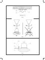
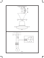
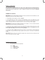
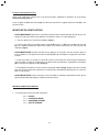
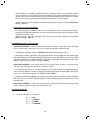
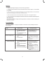
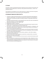
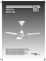
HTS-90
HTS-140
MANUAL DE INSTALACIÓN E INSTRUCCIONES DE USO
Installation Manual and Operating Instructions
NOTICE D’INSTALLATION ET D’UTILISATION
MANUAL DE INSTALAÇÃO E INSTRUÇÕES DE USO
MANUALE D’INSTALLAZIONE E ISTRUZIONI
MONTAGEANLEITUNG UND GEBRAUCHSANWEISUNG
ИНСТРУКЦИЯ ПО МОНТАЖУ И ЭКСПЛУАТАЦИИ
Fig 1
Fig 2
Fig 3
2
Fig 4
OK
Fig 5
Fig 6
3
NO
Fig 7
Fig 8
4
ESPAÑOL
MANUAL DE INSTALACIÓN E INSTRUCCIONES DE USO
Aviso: Lea todas las instrucciones detenidamente para asegurar una operación e instalación
segura del equipo.
Ni el fabricante ni el agente/distribuidor ni el comercio donde se compró este producto tendrán responsabilidad alguna por daños o perdidas ocasionadas por la compra y/o instalación
de este producto.
NORMAS DE SEGURIDAD GENERAL
Para asegurar una instalación segura de su ventilador de techo, lea las siguientes normas de seguridad general antes de iniciar la instalación.
1.-La instalación del ventilador debe llevarse a cabo por un instalador cualificado.
2.-Para asegurar una instalación perfecta, lea el manual de instrucciones y estudie los diagramas antes de iniciar la instalación.
3-Todas las conexiones eléctricas deben conformar con las normas vigentes tanto locales como nacionales. Si no está familiarizado con las instalaciones eléctricas, solicite los servicios de un instalador cualificado.
4.-tensión alimentación: 230V AC 50Hz.
5.-Estos aparatos deberán conectarse a una toma de tierra.
6.-Los medios de desconexión que deben ser incorporados a la instalación fija,para su desconexión
omnipolar de la red de alimentación, deben presentar una separación de contactos de como
mínimo de 3 mm. en todos los polos.
7.-Asegure que el lugar de instalación deje libre la rotación de la hélice del ventilador. La hélice debe
estar como mínimo a 2.30 m. por encima del suelo una vez instalado.
8.-Si va a instalar más de un ventilador asegúrese de no mezclar las palas de las hélices de distintos
ventiladores, aunque sean del mismo modelo.
9.-Antes de empezar a manipular la red eléctrica, quite los fusibles o desconecte el interruptor principal del suministro eléctrico.
10.-Después de instalar el ventilador, asegúrese de que todas las fijaciones estén correctas para evitar la caída del ventilador.
11.-Nunca inserte objetos entre las palas de la hélice mientras el ventilador esté en movimiento.
NOTA IMPORTANTE: Las instrucciones y mecanismos de seguridad que aparecen en este manual
de instrucciones no pretenden cubrir todas las posibles situaciones y condiciones que puedan ocurrir.
Debe entenderse que sentido común, precaución y cuidado son factores que no se puede incluir
dentro del producto. Estos factores lo prestan las personas que mantienen y operan el ventilador.
5
INSTRUCCIONES DE DESEMBALAJE
Antes de montar el ventilador de techo, saque las piezas de dentro del embalaje y compruebe que
todos los componentes de la lista estén incluidos. (Fig.1)
A-
B-
C-
D-
E-
F-
G-
H-
I-
J-
Soporte gancho. (1 Unidad)
Conjunto motor más soporte. (1 Unidad)
Palas. (3 Unidades)
Tornillo fijación palas. (6 Unidades)
Arandela de seguridad. (6 Unidades)
Conjunto regulador de velocidad. (1 Unidad)
Tacos. (2 Unidades)
Tornillos de fijación. (2 Unidades)
Arandela de seguridad. (2 Unidades)
Protección de tela. (3 Unidades)
Manual de instrucciones.
Red de servicios oficiales.
INSTRUCCIONES DE INSTALACIÓN
FIJACION DEL VENTILADOR DE TECHO
NOTA IMPORTANTE: Siga cada una de las indicaciones que se dan a continuación, de esta forma
evitará la posibilidad de provocar un accidente por caída del aparato que podría llegar a derivar en
responsabilidades penales para el instalador.
Asegúrese de que la distancia desde la parte más baja del ventilador, una vez instalado, hasta el
suelo, sea como mínimo de 2.30 metros.
Compruebe que el punto de fijación del aparato sea capaz de soportar el peso del ventilador en
movimiento (mínimo 25Kg).
Fijación en un techo de hormigón
Para asegurar una fijación adecuada, practique dos agujeros en el techo de hormigón del diámetro
del taco (G). Inserte los tacos suministrados y fije el soporte de chapa (A) mediante los dos tornillos
(H) y arandelas (I) suministrados para este propósito. (Fig.2)
Fijación en un techo de poca resistencia
Practique un boquete en el techo falso, suficiente para introducir por él un travesaño rígido de metal
o madera lo más largo posible, y nunca menor de 25 cm. de longitud, a fin de asegurar un mejor
reparto del peso del ventilador.
Sitúe el travesaño de forma que el boquete del techo coincida con su parte central, dónde previamente
se habrá practicado una pequeña ranura de tal forma que no debilite su resistencia mecánica.
Enlace el soporte de chapa (A) mediante sus ranuras, y el travesaño con un alambre de hierro galvanizado de 2.5 mm. de diámetro como mínimo. En ningún caso menos de seis veces, procurando
que alguna de las veces pase por la ranura del travesaño. Al final, sujete bien el alambre con unas
cuantas vueltas sobre si mismo.
Asegúrese que el techo es capaz de soportar el peso del ventilador en movimiento (mínimo 25
Kg.). (Fig. 3)
6
Fijación en una viga de madera
Se suministran dos tornillos (P) y arandelas de seguridad (O) para poder fijar el soporte de chapa
(A) en una viga de madera. El agujero para el tornillo no debe ser de más diámetro que el diámetro
del tornillo.
Asegúrese que la viga de madera sea capaz de soportar el peso del ventilador en movimiento (mínimo 25Kg). (Fig.4)
ENSAMBLAJE DEL VENTILADOR
NOTA IMPORTANTE: Si va a instalar más de un ventilador, asegúrese de no mezclar las palas
de las hélices de distintos ventiladores, aunque sean del mismo modelo.
1.- Coloque las palas según la inclinación mostrada en la figura 5
2.- Una las palas (C) al conjunto motor más soporte (B) mediante los tornillos (D) y las arandelas
de seguridad (E). No olvide poner la protección de tela entre la pala y el motor para evitar posibles
ruidos. Repita este procedimiento con las demás palas. (Fig.6)
NOTA IMPORTANTE: Tenga precaución en no apoyarse sobre las palas, ya que éstas se podrían
desequilibrar y aumentaría el balance del ventilador.
3.- Destornille los dos tornillos situados en la base de la copa decorativa y podrá acceder más
fácilmente al punto de anclaje y a la regleta de conexión. Cuelgue el conjunto motor mas soporte
(B) en el gancho de la plancha de colgar (A) (previamente fijada en el techo). (Fig.7)
4 - Empalme los cables (Fig.8) y ubíquelos correctamente. Mediante la copa decorativa disimule
los empalmes y el punto de fijación. Atornille los dos tornillos situados en la base de la copa
decorativa.
NOTA IMPORTANTE: Antes de empezar a manipular la red eléctrica, quite los fusibles o desconecte el interruptor principal del suministro eléctrico.
INSTRUCCIONES DE OPERACIÓN
1.- El regulador de velocidad, tiene cuatro posiciones:
0 .......... OFF
1 .......... ALTA VELOCIDAD
2 .......... MEDIA VELOCIDAD
3 .......... BAJA VELOCIDAD
7
MANTENIMIENTO
1.- La limpieza periódica es el único mantenimiento requerido.
2.- Limpie el ventilador con un cepillo blanco o un trapo suave para evitar daños al acabado.
3.- En el momento del mantenimiento, tenga precaución en no apoyarse sobre las palas, ya que
éstas se podrían desequilibrar y aumentaría el balanceo del ventilador.
4.- No utilice agentes de limpieza abrasivos, ya que estos pueden dañar el acabado.
5.- No utilice agua en la limpieza del ventilador ya que puede causar daños en el motor.
NOTA IMPORTANTE: Antes de iniciar el mantenimiento del ventilador, asegúrese de que está
desconectado de la red eléctrica.
SOLUCIONAR PROBLEMAS
NOTA IMPORTANTE: Antes de manipular el ventilador, asegúrese de que está desconectado de
la red eléctrica.
Problema
Ventilador no arranca
Causa problema
Solución sugerida
1.Fusibles fundidos o interruptor general desconectado.
2.Conexiones flojas en las regletas de conexión.
1.Comprobar fusibles o interruptor general.
2.comprobar conexiones.
Ventilador ruidoso
3.Palas de la hélice no fijadas
al ventilador
4.Tornillos flojos.
3.Unir palas al ventilador antes
de arrancar.
4.Comprobar todos los tornillos
del ventilador
Ventilador tiembla o vibra
en exceso
5.Tornillos flojos entre las palas
y el soporte motor.
6.Las palas de la hélice no están bien asentadas.
7.El soporte no está bien sujetado al techo.
8.Las palas de la hélice están
fuera equilibrio.
5.Comprobar los tornillos que
fijan las palas a la carcasa del
motor y apretar si es necesario.
6.Comprobar que todas las palas están bien asentadas y con
el mismo ángulo de inclinación.
7.Comprobar el anclaje del soporte gancho.
8.Cambiar unas palas de posición.
8
ENGLISH
Installation Manual and Operating Instructions
Caution : For safe operation and installation, read all instructions carefully
Neither the manufacture nor the manufacturer’s agent/distributor nor the retailer from whom
this product was purchased shall be in anyway responsible for any loss or damage of whatever nature caused by the installation of this product.
GENERAL SAFETY RULES
To ensure the success of the Ceiling Fan’s installation, be sure to read the following general safety
rules before begining .
1- The Ceiling Fan installation should be carried out by a qualified electrician.
2- To ensure a correct installation, be sure to read the instructions and review the diagrams thoroughly before commencement.
3- All electrical connections must be carried out in accordance with local codes and regulations, or
the national Electrical Code. If you are unfamiliar with the installation of electrical wiring, secure
the services of a qualified electrician.
4- Electrical supply 230V AC 50 Hz
5- These apparatus must be earthed.
6- The method of disconnection from the mains supply must incorporate a switch or isolator with
a minimum contact separation of 3 mm.on all poles.
7- Make sure that when the fan is fitted in the chosen position there is not possibility of the rotating
blades coming into contact with any object. Blades should be at least 2.30 m from floor when
fan is hung.
8- If you are installing more than one ceiling fan make sure that you do not mix fan blade sets, even
though they are from the same ceiling fan model.
9- Before beginning, disconnect power by removing fuse or turning off circuit breaker.
10-Once fan installation is completed make sure that all connections are secure to prevent fan from
falling.
11-Do not insert anything into the fan blades when ceiling fan is operating.
IMPORTANT NOTE : The warnings,safeguards and instructions given in this manual are not exhaustive and do not nessecarily cover all eventualities. It must be understood that common sense,
caution and care are factors which cannot be built into any product. These factors must be supplied
by the person(s) caring for and operating the unit.
9
UNPACKING INSTRUCTIONS
Before assembling the ceiling fan, remove all parts from the shipping carton and check them against
the parts listed below (fig. 1 ) :
A- Support plate (1 pc.)
B- Motor assembly and support (1 pc.)
C- Blades (3 pcs.)
D- Blade fitting screw (6 pcs.)
E- Washers (6 pcs.)
F- Speed regulator (1 pc.)
G- Wall plugs (2 pcs.)
H- Screws (2 pcs.)
I- Washers ( 2 pcs.)
J- Felt washers
Instructions Manual
INSTALLATION INSTRUCTION
FITTING THE FAN TO THE CEILING
Important: To avoid the possibility of accidents caused by the fan, which could imply legal responsibilities for the installer, compliance with each of the following instructions is essential.
Ensure that the distance between the lowest point of the fan, once installed, and the floor is at least
2.3 metres.
Check that the means of fitting the fan to the ceiling is capable of supporting the weight of the fan
when in operation. (Minimum25Kg.).
Fitting to a concrete ceiling
To ensure correct installation, drill four holes of the same diameter as the wall plugs (G) in the concrete ceiling. Insert the plugs supplied and fix the support plate (A) using the four screws (H) and
washers (I) provided. (Fig.2).
Fitting to a false ceiling
Make a hole in the false ceiling that is large enough to allow the introduction of a rigid, wooden or
metal cross beam. This should be as long as possible and under no circumstances less than 25cm.
in length, to allow the best distribution of the weight of the fan.
Without reducing its ability to support the fan, make a small groove at the centre of the crossbeam,
then locate the beam so that its centre coincides with the hole in the ceiling.
Join the support plate (A) to the crossbeam using galvanised metal wire of at least 2.5mm in diameter.
Passing the wire through the grooves in the plate, wind it around the crossbeam and back through
the plate a minimum of six times, so that at least some of the turns pass through the groove in the
crossbeam. Secure the wire by twisting it around itself several times.
Ensure that the ceiling is able to support the weight of the fan when in operation (minimum 25Kg.).
(Fig.3)
10
Fitting to a wooden beam
Four screws (P) are supplied together with safety washer’s (O) for fitting the support plate (A) to a
wooden beam. The holes for the screws should not be of greater diameter than the diameter of the
screw. Ensure that the wooden beam is able to support the weight of the moving fan (minimum
25Kg.) (Fig.4)
ASSEMBLY OF THE FAN
IMPORTANT: If you installing more than one fan, ensure that you do not mix the fan blade sets, even
though they are from the same ceiling fan model.
1.- Fit the blades with the angles as shown in figure 5
2.- Fit the blades (C) to the motor assembly and support (B) using the screws (D) and the safety
washers (E). Do not forget to use the felt protection washers between the blade and the motor assembly to avoid possible noise. Repeat this process with the remaining blades. (Fig.6)
IMPORTANT: Be careful not to support yourself on the fan blades, as these could then become
unbalanced and cause vibration or shaking of the fan.
3.- Loosen the screws situated in the base of the decorative canopy to allow easier access to the
anchorage point and electrical connectors. Hang the motor and support assembly (B) from the hook
on the support plate (A) (previously fixed to the ceiling) (Fig.7)
4.- Connect the cables (Fig.8) and position them correctly. The connections and the fitting point
can be hidden using the decorative canopy. Tighten the two screws in the base of the decorative
canopy.
IMPORTANT: Before working on the electrical supply, always remove the fuses or disconnect the
main cut off switch to the mains supply.
OPERATION INSTRUCTIONS
1. – The speed regulator has four positions.
0 .........OFF
1 ......... High speed
2 ......... Medium speed
3 ......... Low speed
11
MAINTENANCE
1.- Periodic cleaning is the only maintenance required.
2.- Clean the fan using a soft brush or soft cloth to avoid damaging the finish.
3.- When carrying out maintenance work, do not use the fan blades as a support as they
could become unbalanced and so increase the vibration of the fan.
4.- Do not use abrasive cleaning agents as these could damage the finish of the fan.
5.- Do not use water when cleaning the fan as this could cause damage to the motor and
deform the fan blades.
IMPORTANT: Before carrying out any maintenance work on the fan, ensure that it is disconnected from the mains electrical supply.
PROBLEM SOLVING
IMPORTANT: Before working on the fan ensure that it is disconnected from the mains electricity
supply.
Problems
Fan
does not start
Fan sounds noisy
Fan sounds noisy
Possible cause
Suggested solution
1. Blown fuse or circuit breaker.
2. Loose connections to the
mains supply
1 . C h e c k f u s e s o r c i rc u i t
breaker.
2. Tighten connections
3. Fan blades not attached to
fan.
4. Loose screws.
3. Fit blades before starting
fan.
5. Loose screws between fan
blades and motor housing.
6. Fan blades not seated properly.
7. Support plate not securely
fitted to ceiling.
8. Fan blades out of balance.
12
4. Check all fan screws for
tightness.
5. Check fan blade screws for
tightness. Tighten if necessary.
6. Check the fan blades sit
snugly in the motor housing
and with the same angle of
inclination.
7. C h e c k c e i l i n g s u p p o r t
screws.
8. Change the position of some
of the blades.
FRANÇAIS
NOTICE D’INSTALLATION ET D’UTILISATION
Avertissement: Lire toute la notice avec attention afin de réaliser une installation sure et bien
utiliser l’appareil.
Ni le fabricant, ni le distributeur, ni le point de vente où a été acheté ce produit, ne sera tenu
responsable des dommages occasionnés par une mauvaise installation.
NORMES GENERALES DE SECURITE
Pour réaliser une installation correcte et sûre du ventilateur de plafond, lire attentivement les
normes de sécurité suivantes ainsi que toute cette notice avant de commencer son montage.
1. L’installation du ventilateur doit être réalisée par un professionnel qualifié.
2. Tous les raccordements électriques doivent être conformes aux normes en vigueur.
3. La tension d’alimentation est de: 230V 50Hz.
4. Ces appareils sont prévus pour être raccordés à une prise de terre.
5. En cas de raccordement direct au réseau, la ligne électrique devra prévoir un interrupteur
omnipolaire ayant une ouverture entre contacts d’au moins 3 mm, bien dimensionné par
rapport à la charge et conforme aux normes en vigueurs.
6. S’assurer que le lieu d’installation permet la libre rotation de l’hélice. Une fois le ventilateur
installé, l’hélice doit se situer à une distance supérieure à 2,30 m au-dessus du sol.
7. Si plusieurs ventilateurs doivent être installés prendre soin de ne pas mélanger les pales des
hélices des différents ventilateurs même s’ils sont identiques.
8. Avant d’installer et de raccorder le ventilateur de plafond vérifier que la ligne d’alimentation
électrique est déconnectée du réseau.
9. Après installation du ventilateur vérifier que toutes les fixations sont correctes pour éviter la
chute du ventilateur.
10. Ne jamais insérer un objet entre les pales du ventilateur quand il est en mouvement.
NOTE IMPORTANTE: Les instructions, quant au montage et la sécurité, données dans cette notice
n’ont pas la prétention de répertorier toutes les situations possibles. Le bon sens et la prudence
sont des facteurs qui doivent être toujours présents pour les personnes utilisant les ventilateurs et
qui en assurent l’entretien.
13
CONTENU DE L’EMBALLAGE
Avant de monter le ventilateur de plafond, sortir toutes les pièces de l’emballage et vérifier que
tous les composants de la liste suivante sont bien présents. (Fig.1)
A-
B-
C-
D-
E-
F-
G-
H-
I-
J-
Support crochet. (1 pièce)
Ensemble moteur-support. (1 pièce)
Pales. (3 pièces)
Vis de fixation des pales. (6 pièces)
Rondelles de sécurité. (6 pièces)
Variateur de vitesse. (1 pièce)
Chevilles. (2 pièces)
Vis de fixation. (2 pièces)
Rondelles de sécurité. (2 pièces)
Protection de pale. (3 pièces)
Notice d’instruction
INSTRUCTIONS D’INSTALLATION
FIXATION DU VENTILATEUR DE PLAFOND
NOTE IMPORTANTE: Suivre toutes les indications données afin d’éviter la chute du ventilateur qui
pourrait entraîner la responsabilité de l’installateur en cas d’accident.
Assurer que la distance entre le point le plus bas du ventilateur, une fois installé, et le sol est supérieure à 2,30 mètres.
S‘assurer que le point de fixation du ventilateur est capable de supporter le poids du ventilateur en
mouvement (minimum 25kg).
Fixation à un plafond en ciment
Pour assurer une fixation correcte, percer le plafond au diamètre des chevilles (G) fournies avec
l’appareil. Insérer les 2 chevilles et fixer le support crochet en tôle (A) avec les vis (H) et rondelles
(I) fournies. (Fig.2)
Fixation à un faux plafond
Après avoir vérifié que le faux plafond est assez résistant pour supporter le ventilateur en mouvement
(minimum 25 kg) (Fig. 3), pratiquer une ouverture dans le faux plafond, suffisamment grande pour
passer une traverse rigide, métallique ou en bois, la plus longue possible, et jamais inférieure à 25
cm de longueur afin de fin d’assurer une bonne répartition du poids.
Faire une petite entaille au centre de la traverse sans que cela ne la fragilise.
Placer la traverse de façon à ce que l’ouverture dans le faux plafond coïncide avec le centre de la
traverse.
Relier le support crochet en tôle (A) avec la traverse avec un fil de fer en acier galvanisé ayant un
diamètre minimal de 2,5 mm. Faire un minimum de 6 tours en passant par la rainure. Finalement
faire quelques tours autour des boucles de fil de fer
14
Fixation à une poutre en bois
Après avoir vérifié que la poutre est assez résistante pour supporter le ventilateur en mouvement
(minimum 25 kg) (Fig. 4).
Deux vis (P) et rondelles de sécurité (O) sont fournies pour fixer le support crochet en tôle (A) à une
poutre en bois.
MONTAGE DU VENTILATEUR
NOTE IMPORTANTE: Si plusieurs ventilateurs doivent être installés prendre soin de ne pas mélanger les pales des hélices des différents ventilateurs même s’ils sont identiques.
1. Placer la pale avec l’inclinaison indiquée figure 5
2. Fixer les pales (C) à l’ensemble moteur-support (B) avec les vis (D) et les rondelles de sécurité
(E) sans oublier la protection (J) entre les pales et le moteur pour limiter les transmissions de
vibrations (Fig.6)
NOTE IMPORTANTE: Prendre soin de ne pas appuyer sur les pales une fois montées pour ne
pas les déformer. Ceci pourrait entraîner un déséquilibre du ventilateur et augmenter son balancement.
3. Dévisser les deux vis situées à la base du cache en forme de cône situé en partie supérieure,
afin d’accéder au point de suspension et au bornier de raccordement. Suspendre le ventilateur
(B) au crochet du support en tôle (A) (Fig.7)
4. Raccorder le ventilateur suivant le schéma électrique indiqué (Fig.8). Replacé le cache conique
pour dissimuler le point de suspension et le bornier de raccordement électrique, puis serrer les
deux vis de fixation.
NOTE IMPORTANTE: Avant d’installer et de raccorder le ventilateur de plafond vérifier que la
ligne d’alimentation électrique est déconnectée du réseau.
INSTRUCTIONS D’UTILISATION
1- Le variateur de vitesse possède 4 positions:
0.........ARRET
1.........GRANDE VITESSE
2.........MOYENNE VITESSE
3.........PETITE VITESSE
15
ENTRETIEN
NOTE IMPORTANTE: Avant de procéder à l’entretien du ventilateur, vérifier que la ligne d’alimentation électrique est déconnectée du réseau.
Au cours du nettoyage faire attention à ne pas prendre appuis sur les pales. Leur déformation pourrait
entraîner un déséquilibre du ventilateur et augmenter son balancement.
1. Un nettoyage régulier est le seul entretien exigé
2. Nettoyer le ventilateur avec un chiffon doux pour ne pas abîmer les pales.
3. Ne pas utiliser de détergent abrasif.
4. Ne pas envoyer d’eau sur le moteur.
SOLUTIONNER DES PROBLEMES SIMPLES
Problème Ventilateur ne démarre
pas
Ventilateur bruyant
Ventilateur vibre excessivement
Cause du problème
Solution suggérée
1. Fusible fondus ou disjoncteur déconnecté.
2. Mauvaise connexion au
bornier de raccordement.
1.Changer le fusible ou enclencher le disjoncteur.
2.Vérifier le raccordement électrique au bornier.
3. Pales mal fixées au moteursupport
4. Vis desserrées 3.Resserrer les vis de fixation
des pales
4. Vérifier toutes les vis de fixation du ventilateur
5. Vis de fixation des pales
desserrées
6. Les pales sont mal montées.
7. Le support est mal fixé au
plafond
8. Le ventilateur est déséquilibré.
5.Vérifier toutes les vis de fixation et les resserrer si nécessaire.
6.Vérifier que toutes les pales soient montées dans le
même sens.
7.Vérifier la fixation du support
crochet.
8.Vérifier que les pales ne
soient pas déformées.
16
PORTUGUÊS
MANUAL DE INSTALAÇÃO E INSTRUÇÕES DE USO
AVISO: Leia atentamente todas as instruções para assegurar um funcionamento e uma instalação segura do equipamento.
Nem o fabricante nem o distribuidor nem o comerciante têm responsabilidade por algum dano
ou perdas ocasionadas pela instalação do aparelho.
NORMAS GERAIS DE SEGURANÇA
Para uma instalação segura do seu ventilador de tecto, leia as seguintes normas de segurança antes
de iniciar a instalação.
1- A instalação do ventilador deve ser executada por um técnico qualificado.
2- Para assegurar uma instalação perfeita, leia o manual de instruções e estude os diagramas antes
de iniciar a instalação.
3- Todas as ligações eléctricas devem conferir as normas locais e nacionais vigentes. Se não está
familiarizado com as instalações eléctricas solicite os serviços de um técnico qualificado.
4- Tensão de alimentação: 230 V AC 50 Hz.
5- Estes aparelhos devem ser ligados a uma ficha com ligação terra.
6- Os meios de interrupção que devem ser incorporados na instalação fixa, para sua interrupção
omnipolar da rede de alimentação, devem apresentar uma separação de contactos com pelo
menos 3 mm em todos os pólos.
7- Assegure-se que o lugar da instalação deixa a rotação da hélice do ventilador livre. A hélice deve
estar a pelo menos 2,30 mts do solo.
8- Se instalar mais do que um ventilador assegure-se para não misturar as palas das hélices de
diferentes ventiladores, mesmo que sejam do mesmo modelo.
9- Antes de começar a instalação na rede eléctrica, retire os fusíveis ou desligue o interruptor principal do alimentador eléctrico.
10-Depois de instalar o ventilador, certifique-se que todas as fixações estão correctas afim de evitar
uma queda do ventilador.
11-Nunca introduza objectos entre as palas da hélice enquanto o ventilador está em movimento.
NOTA IMPORTANTE: As instruções e mecanismos de segurança que aparecem neste manual
de instruções não pretende assegurar todas as possibilidades, situações e condições que podem
ocorrer. Deve-se entender que num sentido comum, precauções e cuidados são factores que não
se pode incluir dentro do produto. Estes factores são detectados pelas pessoas que mantêm e
operam o ventilador.
INSTRUÇÕES PARA DESEMBALAR
Antes de montar o ventilador de tecto, retire as peças de dentro da embalagem e comprove que
todos os componentes da lista estão incluídos (fig.1).
A-
B-
C-
D-
E-
F-
G-
H-
I-
J-
Suporte gancho (1 unidades)
Conjunto motor mais suporte (1 unidades)
Pás (3 unidades)
Parafusos para fixar as pás (6 unidades)
Anilhas de segurança (6 unidades)
Conjunto regulador de velocidade (1 unidade)
Buchas (2 unidades)
Parafusos de fixação (2 unidades)
Anilhas de segurança (2 unidades)
Protecção da tela (3 unidades)
Manual de instruções
17
INSTRUÇÕES DE INSTALAÇÃO
FIXAÇÃO DO VENTILADOR DE TECTO
NOTA IMPORTANTE: Siga cada uma das indicações que se seguem, desta forma evitar-se-á a
possibilidade de provocar um acidente por queda do aparelho, que poderia chegar a derivar em
responsabilidades penais para o instalador.
Assegure-se de que a distância desde a parte mais baixa do ventilador, uma vez instalado, se
situe a pelo menos 2,30 metros do solo.
Comprove que o ponto de fixação do aparelho é capaz de suportar o peso do ventilador em
movimento (no mínimo 25 Kg.).
FIXAÇÃO NUM TECTO DE BETÃO
Para assegurar uma fixação adequada, aplique dois furos no tecto de betão com o diâmetro das
buchas (G). Aplique as buchas fornecidas e fixe o suporte de chapa (A) mediante os dois parafusos
(H) e as anilhas (I) fornecidas para este propósito (fig.2).
FIXAÇÃO NUM TECTO DE POUCA RESISTÊNCIA
Abra uma brecha no tecto falso, suficiente, para introduzir por ela uma trave rígida de metal ou
madeira o mais largo possível e nunca inferior a 25 cm de comprimento, afim de assegurar uma
melhor repartição do peso do ventilador.
Situe a trave, onde previamente se fez uma pequena ranhura, de forma que a brecha do tecto
coincida com a sua parte central, de maneira a não debilitar a sua resistência mecânica.
Fixe o suporte de chapa (A), através das suas ranhuras, e a trave com um arame de ferro galvanizado de 2,5 mm de diâmetro, no mínimo.
Repita este processo pelo menos seis vezes, procurando que algumas das vezes passe pela
ranhura da trave. No final, ajuste bem o arame com algumas voltas em si mesmo.
Assegure-se que o tecto é capaz de suportar o peso do ventilador em movimento (mínimo 25
Kg) (fig.3).
FIXAÇÃO NUMA VIGA DE MADEIRA
Fornece-se os parafusos (P) e as anilhas de segurança (O) para poder fixar o suporte de chapa
(A) numa viga de madeira. O furo para o parafuso não deve ser mais largo que o próprio parafuso.
Certifique-se que a viga de madeira seja capaz de suportar o peso do ventilador em movimento
(mínimo 25 Kg) (Fig.4)
MONTAGEM DO VENTILADOR
NOTA IMPORTANTE: Se for instalar mais de que um ventilador, assegure-se que não são trocadas
as pás das hélices dos ditos ventiladores, nem que sejam do mesmo modelo.
1- Coloque as pás segundo inclinação apresentada na FIGURA 5.
2- Una as pás (C) ao conjunto motor mais suporte (B) mediante os parafusos (D) e as anilhas de
segurança (E). Não hesite em colocar a protecção de tela entre a pá e o motor para, assim, evitar
possíveis ruídos.
Repita este procedimento com as restantes pás (fig.6).
NOTA IMPORTANTE: Tenha a precaução de não se apoiar sobre as pás, pois estas poderão desequilibrar e aumentar o balançar do ventilador.
3- Desaperte os parafusos situados na base da copa decorativa e poderá aceder mais facilmente
ao ponto de encaixe e à régua de ligações.
Pendure o conjunto motor mais suporte no gancho do suporte de chapa (A) (previamente fixado
ao tecto) (fig.7).
4- Junte os cabos (fig.8) e ligue-os correctamente. Com a copa decorativa esconda as junções e
o ponto de fixação. Aparafuse os dois parafusos situados na base da mesma.
NOTA IMPORTANTE: Antes de começar a mexer na rede eléctrica retire os fusíveis ou desligue o
18
interruptor principal do alimentar eléctrico.
INSTRUÇÕES DE FUNCIONAMENTO
1.- O regulador tem quatro posições:
0........ OFF
1........ VELOCIDADE RÁPIDA
2.........VELOCIDADE MÉDIA
3.........VELOCIDADE LENTA
MANUTENÇÃO
1- A limpeza periódica é a única manutenção necessária.
2- Limpe o ventilador com um espanador branco ou um pano suave para evitar danos no acabamento.
3- No momento da manutenção, tenha atenção em não se apoiar sobre as pás, pois estas poderão
desequilibrar e aumentar a balançar do ventilador.
4- Não utilize agentes de limpeza abrasivos, pois estes podem danificar o acabamento.
5- Não utilize água na limpeza do ventilador porque pode causar danos no motor.
NOTA IMPORTANTE: Antes de iniciar a manutenção do ventilador, assegure-se que este está desligado da rede eléctrica.
SOLUCIONAR PROBLEMAS
PROBLEMA
Ventilador não arranca
CAUSA DO PROBLEMA
SOLUÇÃO SUGERIDA
1-Fusíveis fundidos ou interruptor geral desligado.
2-Ligações soltas na régua de
ligações.
1-Verificar fusíveis.
2-Verificar ligações.
Ventilador ruidoso
3- Pás da hélice não fixadas ao
ventilador.
4- Parafusos desapertados.
3- Unir as pás ao ventilador
antes de arrancar.
4- Verificar todos os parafusos
do ventilador.
Ventilador balança ou vibra
em excesso
5- Parafusos desapertados
entre as pás e o suporte motor.
6- As pás da hélice não estão
bem assentes.
7- suporte não está bem ajustado ao tecto.
8- As pás da hélice estão fora
de equilíbrio.
5- Verificar os parafusos que
fixam as pás à carcassa do
motor e apertá-los se for
necessário.
6- Verificar se todas as pás
estão bem assentes e com
o mesmo ângulo de inclinação.
7- Verificar o aperto do suporte
gancho.
8- Trocar a posição das pás.
19
ITALIANO
MANUALE D’INSTALLAZIONE E ISTRUZIONI
Avviso : Leggere tutte le istruzioni attentamente per eseguire correttamente
e con sicurezza l’installazione del prodotto.
Sia il Costruttore, sia l’Agente e o Distributore e o Rivenditore non sono
responsabili per eventuali danni causati dall’installazione di questo prodotto.
NORME GENERALI PER LA SICUREZZA
Per eseguire una installazione sicura del suo ventilatore da soffitto, legga le seguenti norme
di sicurezza generali prima di iniziare l’installazione.
1-L’installazione deve essere effettuata da un installatore qualificato
2-Per una installazione a regola d’arte, legga il manuale delle istruzioni e prenda visione dei
diagrammi prima di iniziare l’installazione.
3-Tutti i collegamenti elettrici devono essere eseguiti in conformità delle normative vigenti a
livello locale e nazionale. Se si è sprovvisti di nozioni per installazioni elettriche rivolgersi
ad un installatore qualificato.
4-Tensioni di alimentazione : 230 V 50 Hz.
5-Questo apparecchio deve essere collegato con messa a terra.
6-Gli accessori elettrici che saranno aggregati all’installazione fissa per l’interruzione della
alimentazione della rete devono avere una separazione dei contatti elettrici di almeno 3
mm .
7-Assicurarsi che l’area interessata all’installazione consenta la rotazione delle pale del
ventilatore e sia libera da ogni potenziale impedimento. Le pale devono essere posizionate
a 2,30 m. minimo dal pavimento.
8-Se l’installazione prevede più di un ventilatore evitare di mescolare le pale anche se si
tratta dello stesso modello.
9-Prima di iniziare i collegamenti , togliere il fusibile o scollegare l’interruttore generale della
rete elettrica.
10-Ad installazione completata assicurarsi che tutti i punti di fissaggio siano perfettamente
bloccati per evitare la caduta del ventilatore.
11-Mai inserire oggetti tra le pale della ventola a ventilatore funzionante.
NOTA IMPORTANTE : Le istruzioni e i concetti di sicurezza che compaiono in questo
manuale non pretendono di far fronte a tutte le situazioni o condizioni particolari che si possono evidenziare al momento dell’installazione. E’ evidente che il buon senso unitamente
a precauzione e attenzione sono fattori che non si possono includere in nessun manuale e
che sono patrimonio delle persone qualificate che installano e manipolano il ventilatore.
20
ISTRUZIONE DI DISIMBALLO
Prima di procedere al montaggio del ventilatore da soffitto , togliere tutti i componenti della
lista inclusa. ( Fig. 1 )
A- Supporto gancio ( 1 pezzo )
B- Gruppo motore con supporto ( 1 pezzo )
C- Pale ( 3 pezzi )
D- Viti per il fissaggio delle pale ( 6 pezzi )
E- Rondelle di sicurezza ( 6 pezzi )
F- Regolatore di velocità ( 1 pezzo )
G- Tasselli ( 2 pezzi )
H- Viti di fissaggio ( 2 pezzi )
I- Rondelle di sicurezza ( 2 pezzi )
J- Protettori in tela ( 3 pezzi )
Manuale d’istruzione
ISTRUZIONI PER L’INSTALLAZIONE
FISSAGGIO DEL VENTILATORE AL SOFFITTO
NOTA IMPORTANTE : Seguire attentamente ogni indicazione che segue per evitare la
possibilità di provocare incidenti per la caduta del ventilatore che potrebbero comportare
una responsabilità penale per l’installatore.
Accertarsi che la distanza dal punto più basso del ventilatore installato , al pavimento sia
come minimo di 2,30 metri.
Controllare e verificare che il punto di fissaggio del ventilatore sia capace di sostenere il
peso del ventilatore in movimento ( minimo 25 Kg. )
Fissaggio a soffitto in cemento
Praticare due fori nel soffitto del diametro del tassello ( G ) . Inserire i tasselli forniti e fissare
il supporto in lamiera ( A) con le viti ( H ) e le rondelle ( I ) ( Fig. 2 )
Fissaggio a un soffitto di scarsa resistenza.
Praticare una apertura nel falso soffitto sufficiente, per l’introduzione di una traversa rigida
in metallo o di legno la più lunga possibile e in ogni caso non inferiore ai 25 cm di lunghezza
con lo scopo di meglio ripartire il peso del ventilatore.
Posizionare la traversa in modo che la svasatura del soffitto coincida con la sua parte centrale
, dove preventivamente si sarà praticata una piccola scanalatura che non comprometta la
sua resistenza meccanica.
Legare il supporto in lamiera ( A ) per mezzo delle scanalature e la traversa con del filo
metallico zincato del diametro di 2,5 mm minimo. Eseguire almeno sei legature assicurandosi che il filo sia ben inserito nella scanalatura della traversa. Serrare bene il filo metallico
assicurandosi che la traversa sia bloccata.
Assicurarsi che il soffitto sia capace di sopportare il peso del ventilatore in movimento
( minimo 25 Kg ) . ( Fig.3 )
21
Fissaggio in una trave di legno
Vengono fornite due viti ( P ) e rondelle di sicurezza ( O ) per il fissaggio del supporto in
lamiera ( A ) ad una trave il legno. Assicurarsi delle forature che devono avere lo stesso
diametro delle viti.
Assicurarsi che il soffitto sia capace di sopportare il peso del ventilatore in movimento (
minimo 25 Kg ) . ( Fig.4 )
MONTAGGIO DEL VENTILATORE
NOTA IMPORTANTE : Se si installano più ventilatori evitare di mescolare le pale anche se
si tratta dello stesso modello.
1- Montare le pale secondo l’inclinazione indicata nella figura 5.
2- Unire le pale ( C ) al gruppo motore-supporto ( B ) con le viti ( D ) e le rondelle di sicurezza (E ). Non dimenticare di inserire la protezione di tela tra la pala e il motore per
evitare possibili rumori. Ripetere la stessa operazione con le altre pale ( Fig. 6 ).
NOTA IMPORTANTE : Fate ben attenzione a non appoggiarvi alle pale o a deformarle
in quanto potrebbero sbilanciare il ventilatore e comprometterne il buon funzionamento.
3- Svitare le due viti situate nella coppa decorata e si potrà accedere più facilmente al
punto di ancoraggio e alla morsettiera elettrica. Appendere il gruppo motore e supporto ( B ) all’apposito gancio ( A ) ( Fig. 7 )
4- Eseguire il collegamento elettrico ( Fig. 8 ) e nascondere l’eccesso del collegamento
all’interno della coppa decorata fissata con le apposite viti.
NOTA IMPORTANTE : Prima di iniziare i collegamenti , togliere il fusibile o scollegare
l’interruttore generale della rete elettrica.
ISTRUZIONI DI FUNZIONAMENTO
1- Il regolatore di velocità dispone di quattro posizioni:
0....... . SPENTO
1........ ALTA VELOCITA’
2.........MEDIA VELOCITA’
3........ BASSA VELOCITA’
22
MANUTENZIONE
1- La pulizia periodica è la sola manutenzione da eseguire.
2- Pulire il ventilatore con una spazzola o un canovaccio soffice per evitare graffi
alle parti verniciate.
3- Nel pulire evitare di appoggiarsi o sostenersi alle pale del ventilatore che si potrebbero deformare pregiudicando un buon funzionamento dell’apparecchio.
4- Non utilizzare prodotti per la pulizia abrasivi.
5- Non impiegare acqua o altri liquidi per la pulizia del motore.
NOTA IMPORTANTE : Prima di procedere alla pulizia del ventilatore assicurarsi
che sia scollegato dalla rete elettrica.
RISOLUZIONE DEI PROBLEMI
NOTA IMPORTANTE : Prima di procedere a qualsiasi intervento assicurarsi che
il ventilatore sia scollegato dalla rete elettrica.
Problema Causa del problema Il ventilatore non parte
1-Il fusibile è guasto o
l’interruttore generale è scollegato
2-Il collegamento elettrico è
mal eseguito
1-Verificare il fusibile e
l’interruttore generale
2-Verificare il collegamento
serrando bene le viti dei
morsetti
Ventilatore rumoroso
1-Le pale non sono ben fissate
al motore
2- Viti allentate
1-Le pale non sono ben fissate
al motore
2-Le pale non sono collocate correttamente nella loro
sede.
3-Il supporto non è ben fissato
al soffitto
4-Le pale del ventilatore sono
deformate
1-Fissare le pale al motore prima dell’avviamento
2-Verificare tutte le viti di fissaggio del ventilatore
Ventilatore vibra o oscilla
23
Soluzione suggerita
1-Verificare le viti che fissano
le pale al motore e serrarle
se necessario.
2-Verificare che le pale siano
ben assestate e ben collocate nella loro sede.
3-Verificare l’ancoraggio del
gancio del supporto
4-Cambiare la posizione delle
pale.
DEUTSCH
MONTAGEANLEITUNG UND GEBRAUCHSANWEISUNG
Hinweis: Lesen Sie die folgenden Anweisungen aufmerksam durch, um eine sichere Montage und einen sicheren Betrieb des Geräts zu gewährleisten.
Weder der Hersteller noch der Händler/Vertreiber oder Einzelhändler haften für die durch
die Montage dieses Produkts entstandenen Schäden und Verluste.
ALLGEMEINE SICHERHEITSVORSCHRIFTEN
Bitte lesen Sie folgende Sicherheitsvorschriften, um eine sichere Montage Ihres Deckenventilators
zu gewährleisten.
1.- Die Montage des Ventilators muss von qualifiziertem Fachpersonal durchgeführt werden.
2.- Um eine einwandfreie Montage zu gewährleisten, lesen Sie bitte vor der Montage die Gebrauchsanweisung und schauen Sie sich die Abbildungen an.
3- Alle elektrischen Anschlüsse müssen den gültigen lokalen sowie nationalen Vorschriften entsprechen. Wenn Sie mit Elektroinstallationen nicht vertraut sind, wenden Sie sich an einen qualifizierten Installateur.
4.- Versorgungsspannung: 230V AC 50Hz.
5.- Geräte dieser Art müssen geerdet werden.
6.- Die zur polgleichen Trennung der Verbindung des fest montierten Geräts zum Stromnetz vorzusehenden Mittel müssen einen Mindestkontaktabstand von 3 mm zwischen allen Polen aufweisen.
7.- Stellen Sie sicher, dass am Montageort genügend Raum für die rotierenden Ventilatorflügel zur
Verfügung steht. Nach Montage des Ventilators muss der Abstand der Flügel zum Boden mindestens 2,30 m betragen.
8.- Falls Sie mehrere Ventilatoren montieren, achten Sie darauf, die Flügel nicht zu vertauschen,
selbst wenn es sich um Geräte des gleichen Modells handelt.
9.- Drehen Sie vor Arbeiten am Stromnetz die Sicherungen heraus oder schalten Sie die Stromversorgung am Hauptschalter ab.
10.-Überprüfen Sie nach erfolgter Montage den richtigen Sitz aller Befestigungselemente, um ein
Herabfallen des Ventilators auszuschließen.
11.-Halten Sie niemals Gegenstände in die laufenden Ventilatorflügel.
WICHTIGER HINWEIS: Die in dieser Gebrauchsanweisung erwähnten Sicherheitseinrichtungen
und die Sicherheitshinweise sind nicht für alle denkbaren Gefahrensituationen und Bedingungen
gedacht. Aspekte wie gesunder Menschenverstand, Vorsicht und Sorgfalt können selbstverständlich nicht zum Lieferumfang gehören. Diese müssen vom Bedienungs- und Wartungspersonal gestellt werden.
24
AUSPACKEN DES GERÄTS
Vor der Montage entnehmen Sie die Bauteile des Deckenventilators aus der Verpackung und
überprüfen Sie die Vollständigkeit anhand der folgenden Packliste: (Abb..1)
A- Hakenhalterung. (1 Stück)
B- Baugruppe Motor-Halterung. (1 Stück)
C- Flügel. (3 Stück)
D- Befestigungsschrauben Flügel. (6 Stück)
E- Sicherungsscheibe. (6 Stück)
F- Baugruppe Drehzahlregler. (1 Stück)
G- Dübel. (2 Stück)
H- Befestigungsschrauben. (2 Stück)
I- Sicherungsscheibe. (2 Stück)
J- Stoffscheibe. (3 Stück)
Gebrauchsanweisung.
MONTAGEANLEITUNG
BEFESTIGUNG DES DECKENVENTILATORS
WICHTIGER HINWEIS: Durch korrektes Befolgen jeder einzelnen der folgenden Anweisungen
werden mögliche Unfälle durch Herabfallen des Geräts vermieden, die überdies strafrechtliche
Konsequenzen für den Installateur haben können.
Stellen Sie sicher, dass der Abstand des tiefsten Punktes des Ventilators zum Boden nach der
Montage mindestens 2,30 Meter beträgt.
Vergewissern Sie sich, dass der Befestigungspunkt des Geräts das Gewicht des laufenden Ventilators aushält (mindestens 25 kg).
Befestigung an einer Betondecke
Um eine geeignete Befestigung zu gewährleisten, bohren Sie dem Durchmesser des Dübels (G)
entsprechend zwei Löcher in die Betondecke. Stecken Sie die mitgelieferten Dübel hinein und
befestigen Sie das Halteblech (A) mit den beiden zu diesem Zwecke mitgelieferten Schrauben
(H) und Unterlegscheiben (I). (Abb.2)
Befestigung an einer Decke mit geringer Tragfähigkeit.
Schneiden Sie eine Öffnung in die abgehängte Decke, ausreichend zum Einbringen einer möglichst langen Holz- oder Metallleiste (mindestens jedoch 25 cm lang), um das Ventilatorgewicht
besser zu verteilen.
Versehen Sie die Leiste im mittleren Bereich mit einer Nut, ohne jedoch deren mechanische
Festigkeit zu gefährden, und richten Sie die Leiste so aus, dass diese Nut über der Deckenöffnung zu liegen kommt.
25
Verbinden Sie das Halteblech (A) über die darin vorhandenen Nuten und die Leiste mit Hilfe
eines mindestens 2,5 mm starken verzinkten Stahldrahts. Umwickeln Sie beide Elemente mindestens sechs mal und achten Sie darauf, dass eine der Windungen in der Leistennut zu liegen
kommt. Zum Schluss verzwirbeln Sie die beiden Drahtenden fest miteinander.
Stellen Sie sicher, dass die Decke das Gewicht des laufenden Ventilators aushält (mindestens
25 kg). (Abb. 3)
Befestigung an einem Holzbalken
Zur Befestigung des Halteblechs (A) an einem Holzbalken werden zwei Schrauben (P) mit
Sicherungsscheiben (O) mitgeliefert. Der Durchmesser des Bohrlochs darf nicht größer als die
Stärke der Schrauben sein.
Stellen Sie sicher, dass der Holzbalken das Gewicht des laufenden Ventilators aushält (mindestens 25 kg). (Abb.4)
ZUSAMMENBAU DES VENTILATORS
WICHTIGER HINWEIS: Falls Sie mehrere Ventilatoren montieren, achten Sie darauf, die Flügel
nicht zu vertauschen, selbst wenn es sich um Geräte des gleichen Modells handelt.
1.- Bringen Sie die Flügel mit der in Abbildung 5 gezeigten Neigungsrichtung an.
2.- Befestigen Sie den Flügel (C) an der Baugruppe Motor-Halterung (B) unter Verwendung der
Schrauben (D) und Sicherungsscheiben (E). Vergessen Sie nicht, den Stoffschutz zwischen Flügel
und Motor einzulegen, um damit mögliche Geräusche zu vermeiden. Wiederholen Sie die angegebenen Schritte mit den restlichen Flügeln. (Abb.6)
WICHTIGER HINWEIS: Bitte stützen Sie sich nicht auf die Flügel, da dies zu Unwucht führen
und somit das Schlingern des Ventilators verstärken könnte.
3.- Lösen Sie die Schrauben am Fuß der Zierkappe, um leichteren Zugang zum Befestigungspunkt
und zur Anschlussleiste zu erhalten. Hängen Sie die Baugruppe Motor-Halterung (B) in den Haken
des zuvor an der Decke angebrachten Halteblechs (A). (Abb.7)
4 - Schließen Sie Kabel an (Fig.8) y verlegen Sie sie ordnungsgemäß. Schieben Sie die Zierkappe
über die Anschlüsse und den Befestigungspunkt. Ziehen Sie die beiden Schrauben am Fuß der
Zierkappe fest.
WICHTIGER HINWEIS: Drehen Sie vor Arbeiten am Stromnetz die Sicherungen heraus oder
schalten Sie die Stromversorgung am Hauptschalter ab.
BETRIEBSHINWEISE
1.- Der Drehzahlregler hat vier Stufen:
0.............EIN
1.............SCHNELL
2.............NORMAL
3.............LANGSAM
26
WARTUNG
1.- Außer regelmäßiger Reinigung ist keinerlei Wartung erforderlich.
2.- Reinigen Sie den Ventilator mit einer Bürste oder einem weichen Lappen, um Lackschäden
zu vermeiden.
3.- Bitte stützen Sie sich während der Reinigung nicht auf die Flügel, da dies zu Unwucht führen
und somit das Schlingern des Ventilators verstärken könnte.
4.- Bitte verwenden Sie keine scheuernden Mittel, da diese den Lack angreifen könnten.
5.- Bitte verwenden Sie zum Reinigen des Ventilators kein Wasser, da dadurch der Motor geschädigt werden könnte.
WICHTIGER HINWEIS: Vor Beginn der Wartungsarbeiten am Ventilator ist dieser unbedingt vom
Stromnetz zu trennen.
FEHLERBEHEBUNG
WICHTIGER HINWEIS: Vor Beginn der Arbeiten am Ventilator ist dieser unbedingt vom Stromnetz zu trennen.
Fehler
Fehlerursache
Lösungsvorschlag
Ventilator läuft nicht an
1. Durchgebrannte Sicherungen oder Hauptschalter
aus.
2. Lose Verbindungen an der
Anschlussleiste
1.Sicherungen oder Hauptschalter überprüfen.
2.Anschlüsse überprüfen
Erhöhte Laufgeräusche
3. Flügel nicht am Gerät befestigt
4. Lose Schrauben..
3.Vor dem Starten des Ventilators Flügel am Gerät befestigen.
4.Alle Schrauben am Ventilator
überprüfen
Zu starkes Vibrieren oder
Rütteln des Ventilators
5. Lose Befestigungsschrauben der Flügel am Motorgehäuse
6. Schlechter Sitz der Ventilatorflügel
7. Schlechte Befestigung der
Halterung an der Decke.
8. Unwucht der Ventilatorflügel
27
5.Befestigungsschrauben der
Flügel am Motorgehäuse
überprüfen und bei Bedarf
anziehen.
6.Richtigen Sitz und gleichen
Neigungswinkel aller Flügel
sicherstellen.
7.Verankerung der Hakenhalterung überprüfen.
8.Flügel gegeneinander austauschen.
РУССКИЙ
Пожалуйста, перед установкой вентилятора, внимательно изучите данную инструкцию. Она
содержит важную информацию по монтажу и обслуживанию вентилятора, а также по технике безопасности.
Производитель или продавец не несут ответственности за ущерб, полученный вследствие
неправильного монтажа или эксплуатации данного оборудования.
ОСНОВНЫЕ ПРАВИЛА БЕЗОПАСНОСТИ
1. Установка и подключение вентилятора к сети электропитания должно производиться
специально обученным и аттестованным персоналом, имеющим на это разрешение, в
соответствии с «Правилами устройства электроустановок» и правилами техники безопасности.
2. Для подключения вентилятора к сети электропитания используйте схемы, приведенные
в данной инструкции и на самом оборудовании.
3. Параметры электропитания: 1ф – 230 В – 50 Гц.
4. Оборудование требует заземления.
5. Подвод электропитания должен осуществляться через двухполюсный автоматический
выключатель с зазором между контактами не менее 3 мм.
6. Расстояние от лопастей вентилятора до пола должно быть больше 2,3 м. Убедитесь, что в
положении, выбранном для установки, лопасти вентилятора не будут контактировать с
какими-либо посторонними предметами.
7. Если вы устанавливаете несколько вентиляторов, не путайте лопасти одного вентилятора с другим. Устанавливайте на вентилятор те лопасти, которые были с ним в комплекте,
даже если вентиляторы одной модели.
8. Перед установкой и подключением вентилятора, проверьте, чтобы кабель подвода
электропитания был обесточен.
9. После установки вентилятора проверьте его крепление, не должно быть никакой возможности для падения вентилятора.
10.Удостоверьтесь, что никакие предметы не смогут попасть в лопасти вентилятора во время его работы.
11.Данная инструкция не может описать все нестандартные ситуации, которые могут произойти в процессе установки оборудования. За безопасность работ по монтажу, а также
дальнейшей работы оборудования несет ответственность лицо, которое устанавливает
или эксплуатирует данное оборудование.
28
РЕКОМЕНДАЦИИ ПО РАСПАКОВКЕ
Прежде чем приступить к сборке вентилятора проверьте комплектность товара (Рис.1/Fig.1),
в соответствии с нижеприведенными данными:
A – Крепежная пластина (1 шт.)
B – Электродвигатель (1 шт.)
С – Лопасть (3 шт.)
D – Винт (6 шт.)
E – Шайба (6 шт.)
F – Регулятор скорости (1 шт.)
G – Дюбель (2 шт.)
H – Шуруп (2 шт.)
I – Шайба (2 шт.)
J – Картонная шайба (3 шт.)
Инструкция по монтажу и эксплуатации
УСТАНОВКА
Крепление вентилятора к потолку.
Для предотвращения нестандартных ситуаций, связанных с работой вентилятора, необходимо
обеспечить расстояние от пола до лопастей вентилятора не менее 2,3 м. Также следует удостовериться, что конструкция потолка способна выдержать вес вентилятора, работающего
на максимальной скорости: мин. 25 кг.
Крепление вентилятора к бетонному потолку.
Сделайте в бетонном потолке четыре отверстия диаметром, соответствующим диаметру
дюбелей (G). Вставьте дюбели в отверстия в бетоне и закрепите крепежную пластину (A) при
помощи четырех шурупов (H) и шайб (I) (Рис.2/Fig.2).
Крепление вентилятора к подвесному потолку.
Возьмите подходящую перекладину (деревянную или металлическую) для равномерного
распределения веса вентилятора по плоскости потолка (длиной не менее 25 см) (Рис.3/Fig.3).
Сделайте по центру перекладины неглубокую канавку, таким образом, чтобы не ослабить
несущие способности перекладины. Проделайте в подвесном потолке отверстие и введите
перекладину в пространство подвесного потолка. Расположите перекладину таким образом,
чтобы центр перекладины совпадал с центром отверстия в потолке. При помощи металлической оцинкованной проволоки (мин диам. 2,5 мм) сильно примотайте крепежную пластину (А)
к перекладине так, чтобы проволока проходила по канавке на перекладине и не смещалась в
сторону. Убедитесь, что полученная конструкция выдержит вес работающего вентилятора (мин.
25 кг) и, что крепежная пластина (А) прочно примотана к перекладине и не шевелится.
Крепление вентилятора к деревянной балке.
В деревянной балке проделайте четыре отверстия диаметром, меньшим, чем диаметр шурупов
(P). (Рис.4/Fig.4). Закрепите крепежную пластину (А) при помощи четырех шурупов (P) и шайб
(O). Убедитесь, что деревянная балка выдержит вес работающего вентилятора (мин. 25 кг).
29
СБОРКА ВЕНТИЛЯТОРА
Если вы устанавливаете несколько вентиляторов, не путайте лопасти одного вентилятора с
другим. Устанавливайте на вентилятор те лопасти, которые были с ним в комплекте, даже если
вентиляторы одной модели.
1.-Установите лопасти вентилятора в правильном положении, как показано на (Рис.5 /
Fig.5).
2.-Закрепите лопасти (С) на электродвигателе (В), используя винты (D) и шайбы (Е). Также,
следует проложить картонные шайбы (J) между лопастью вентилятора и электродвигателем, это уменьшит вибрации и шум от вентилятора. Проделайте такие же операции с
оставшимися лопастями (Рис.6 / Fig. 6).
ВАЖНО: не прикладывайте чрезмерных нагрузок к лопастям вентилятора, чтобы не
погнуть их, т.к. это может привести к дисбалансу вентилятора и появления вибраций и
шума.
3.-Ослабьте винт, расположенный на основании декоративного колпака и сдвиньте его вниз.
Повесьте собранный вентилятор (B) на крюк, расположенный на основании (А) (основание
предварительно должно быть прочно закреплено на потолке) (Рис.7 / Fig.7).
4.-Проложите кабель в нужном направлении и подключите его к сети электропитания (Рис.8
/ Fig.8). Закройте место подключения декоративным колпаком и затяните фиксирующий
винт.
ВАЖНО: прежде чем выполнять какие-либо действия по подключению вентилятора,
удостоверьтесь, чтобы кабель подвода электропитания был обесточен.
ЭКСПЛУАТАЦИЯ
Регулятор скорости имеет четыре положения.
0 – Выкл.
1 – Высокая скорость
2 – Средняя скорость
3 – Низкая скорость
ОБСЛУЖИВАНИЕ
Перед проведением обслуживания убедитесь, что вентилятор выключен, а кабель подвода
электропитания обесточен.
1. Вентилятор необходимо периодически очищать от пыли при помощи мягкой ткани. Во
избежание порчи вентилятора не используйте твердые чистящие принадлежности, воду
и абразивные моющие средства.
2. Лопасти вентилятора протирайте осторожно, не прилагайте к ним чрезмерных усилий,
чтобы не нарушить балансировку вентилятора.
30
ВОЗМОЖНЫЕ НЕИСПРАВНОСТИ
Проблема
Неисправность
Возможные решения
Вентилятор не
включается
1. Перегорел
предохранитель или
сработал автоматический
выключатель.
2. Нарушен контакт на
клеммах вентилятора
1. Проверьте предохранитель и
автоматический выключатель.
2. Проверьте контакты на клеммах
вентилятора.
От вентилятора исходит
посторонний звук
1. Лопасти не установлены на
вентилятор.
2. Ослабли винты на
вентиляторе.
1. Установите лопасти на вентилятор
перед его запуском.
2. Подтяните (не чрезмерно) все
винты на вентиляторе.
Чрезмерная вибрация
вентилятора
1. Отвинтились винты
крепления лопастей.
2. Лопасти установлены не
правильно.
3. Крепежная пластина
не достаточно сильно
закреплена.
4. Лопасти вентилятора не
сбалансированы.
1. Подтяните (не чрезмерно) винты
крепления лопастей.
2. Убедитесь, что лопасти плотно
закреплены на консолях и
электродвигателе. Если это не
помогло – разберите и соберите
вентилятор снова.
3. Подтяните шурупы крепежной
пластины.
4. Поменяйте лопасти местами.
ВАЖНО:
Не рекомендуется разбирать или заменять любые части устройства самостоятельно,
потому что это автоматически приведет к аннулированию заводской гарантии.
В случае неисправности оборудования следует обратиться к официальному представителю компании Soler&Palau в вашем регионе.
Компания Soler&Palau оставляет за собой право вносить изменения в конструкцию оборудования без предварительного уведомления.
31
Ref. 1431142-1
C/Llevant,4
Polígono Industrial Llevant
08150 Parets del Vallès
(Barcelona) ESPAÑA
Tel. 93 571 93 00
Fax. 93 571 93 01
Tel. int. +34 93 571 93 00
Fax. int. +34 93 571 93 11
http://www.solerpalau.com
[email protected]