1
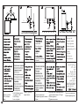
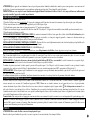
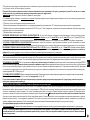
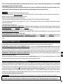
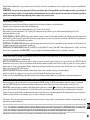
SCALDAQUA ELETTRICI AD ACCUMULO
Accumulo Smaltato
N : .................................................
......./......./20.......
9954-0766 J
I
BL
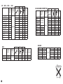
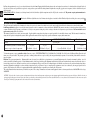
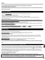
PC / GP+ / GTS + / GH
PUISSANCE
/OUTPUT
W (BT)
10 S / GTS+ 10
10 R / GP+ 10
15 S / GTS + 15
15 R/GP + 15
15 SB (compact)
15 RB (compact)
30 / GP + 30
50 / GP + 50
GTS + 30
GTS +50
GH 30
GH 50
2
3
2
3
2
3
2
2
2
3
3
6
6
P.5
PUISSANCE
/OUTPUT
W (BT)
1500
2100
2100
P.5
P.6
9.1/10.1
9.2/10.2
9.1/10.1
9.2/10.2
9.1/10.1
9.2/10.2
9.2/10.2
9.2/10.2
9.6
9.6
9.5
9.5
P.6-7
230
A1
A1
A1
A1
A1
A1
A1
A1
A1
A1
A1
A1
5/6
5/6
5/6
9.2/9.5
9.2/9.5
9.2/9.5
0,63
0,48
0,70
0,57
0,70
0,58
0,76
1,13
0,76
1,13
0,90
1,10
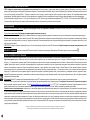
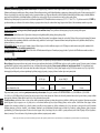
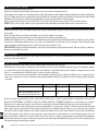
PUISSANCE
/OUTPUT
W (BT)
HM 75/ GH 75
1600
VM 301600
HM 100/ GH 100
VM 50
HM 150 / GH 150
2200
VM 80
HM 200 /GH 200
2200
VM 100
HM RS 75 (magnésium)VM 120
1200
HM RS 100(magnésium)WM 50
1800
WM 80
HM RS 150 (magnésium)
1800
WM 100
HM RS 200 (magnésium)
1800
HM 50
HM RS 75/ GH 75ACI+ HM 801200
HM RS 100/GH 100ACI HM
+ 100
1800
HM RS 150/ GH 150ACI +
1800
HM RS 200/ GH 200ACI +
2400
HM RS 150 (ACI)
1800
HM RS 200 (ACI)
1800
230
F2
F2
F2
1200
1200/1500
1600/2000
1500
1500
1500
1500
1500
1500
P.4
TENSION
VOLTAGE
(V)
8
8
8
8
8
220/240
8
8
8
8
8
8
8
8
8
P.5
P.6
kW/
24H
9.3
9.3
9.3
9.3
9.3
9.3
9.3
9.3
9.3
9.3
9.3
9.3
9.3
9.3
230
A3
4 / 5 A3
4/5
A3
4/5
4 / 5 A3
4 / 5 H1
4 / 5 H1
4 / 5 I1
4 / 5 I1
7
7 L1
7 L1
L1
L1
M1
M1
400 TC
9.2
9.2
9.2
9.2
9.2
9.2
9.2I2
9.2I2
9.3
9.3
9.3
M2
M2
230
1,09
A1
1,24
A1
1,59
A1
1,96
A1
1,09
A1
1,24
F2
F2
1,59
F2
1,96
A1
1,09
A1
1,24
A1
1,59
1,96
1,59
1,96
136
0,80
178
0,88
266
1,23
352
1,62
136
1,73
178
0,96
1,33
266
1,66
352
1,10
136
1,34
178
1,85
266
352
266
352
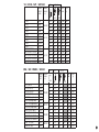
N4 SASO
P.8
TENSION
VOLTAGE
(V)
220/240
N4/N4E/E-SERIES/CONCEPT/N4C
kW/
24H
1200/2000
1200/1600
1200/2000
1500/2000
2000
1200/1600
220/240
1500/2000
1500/2000
2000
2000
2000
2000
N3C
VM 30 cm
VM 50 cm
VM 80 cm
P.4
TENSION
VOLTAGE
(V)
kW/
24H
(vertical)
kW/
24H
(horizontal)
0,75
1,01
1,41
1,15
1,35
1,66
VM 30
VM 50
VM 80
VM 100
HM 50
HM 80
HM 100
1100
1830
1830
1830
1370
1370
1370
127/220
4/5
4/5
4/5
4/5
7
7
7
9.2
9.2
9.2
9.2
9.3
9.3
9.3
A1
A1
A1
A1
A1
A1
A1
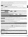
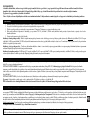
VS / VS RS /GZT / GZT ACI
PUISSANCE
/OUTPUT
W (BT)
VS 150
VS 200
VS 250
VS 300
VS 150
VS 200
VS 250
VS 300
VS 400
VS 500 / GZT 500
VSRS 150/GZT 150 ACI
VSRS 200/GZT 200 ACI
VSRS 250/ GZT 250 ACI
VSRS 300 /GZT 300 ACI
P.5
P.6 / 8
TENSION
VOLTAGE
(V)
2200
2200
220/240
3000
3000
2200/2500
2500
400 TC
3300/4500
3300/4500
-/5000
5000
1800/2700
2400/2700 400 TC
3000
3000
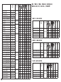
HM / GH / HM RS / GH ACI
9.4
9.4
9.4
9.4
9.4
9.4
9.4
9.4
9.4
9.4
9.4
9.4
9.4
9.4
230
A3
A3
A3
A3
C1
C1
C1
C1
D1
D1
M1
M1
M1
M1
P.4
P.5
kW/
24H
Q 40°C
(l)
1,69
2,06
2,41
2,73
1,69
2,06
2,41
2,73
2,70
3,48
1,69
2,06
2,41
2,73
261
366
453
573
261
366
453
573
261
366
453
573
400TC
C2
C2
C2
C2
D2
D2
M2
M2
M2
M2
P.6 / 8
PUISSANCE TENSION
/OUTPUT VOLTAGE
W (BT)
(V)
3
2
3
2
3
2
2
2
3
3
6
6
9.1/10.1
9.2/10.2
9.1/10.1
9.2/10.2
9.1/10.1
9.2/10.2
9.2/10.2
9.2/10.2
9.6
9.6
9.5
9.5
230
A1
A1
A1
A1
A1
A1
A1
A1
A1
A1
A1
A1
0,63
0,48
0,70
0,57
0,70
0,58
0,76
1,13
0,76
1,13
0,90
1,10
HM 75/ GH 75
HM 100/ GH 100
HM 150 / GH 150
HM 200 /GH 200
HM RS 75 (magnésium)
HM RS 100(magnésium)
HM RS 150 (magnésium)
HM RS 200 (magnésium)
HM RS 75/ GH 75ACI+
HM RS 100/GH 100ACI +
HM RS 150/ GH 150ACI +
HM RS 200/ GH 200ACI +
HM RS 150 (ACI)
HM RS 200 (ACI)
1600
1600
2200
2200
1200
1800
1800
1800
1200
1800
1800
2400
1800
1800
220/240
400 TC
220/240
400 TC
8
8
8
8
8
8
8
8
8
8
8
8
8
8
9.3
9.3
9.3
9.3
9.3
9.3
9.3
9.3
9.3
9.3
9.3
9.3
9.3
9.3
230
A3
A3
A3
A3
H1
H1
I1
I1
L1
L1
L1
L1
M1
M1
kW/
24H
Q 40°C
(l)
1,09
1,24
1,59
1,96
1,09
1,24
1,59
1,96
1,09
1,24
1,59
1,96
1,59
1,96
136
178
266
352
136
178
266
352
136
178
266
352
266
352
400 TC
I2
I2
M2
M2
3
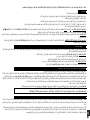
PUISSANCE
/OUTPUT
W (BT)
VM 50 / GV 80
900 / 1200
VM 75 / GV 80
1200/2200
VM 100/ GV 100
1200 /2200
VM 150/GV 150/CONCEPT 1600/2200
VM 200/GV 200/CONCEPT
2200
VM 150 TC
1650
VM 200 TC
2200
VMA 50
3000
VMA 75
3000
VMA 100
3000
VMA 150
3000
VMA 200
3000
VM RS 50 (magnésium)
900/1200
VM RS 75 (magnésium)
1200
VM RS 100 (magnésium)
1200
VM RS 150 (magnésium)
1800
VM RS 200 (magnésium)
2400
VM RS 50 /GV50 ACI+ 900/1200/1800
VM RS 75 /GV75 ACI +
1200/2400
VM RS 100/GV100 ACI+
1200/2400
VM RS 150 /GV150 ACI + 1800/2400
VM RS 200 /GV200 ACI + 2400/3000
VMA RS 50(magnésium)
1800
VMA RS 75(magnésium) 2400/3000
VMA RS 100(magnésium) 2400/3000
VMA RS 150(magnésium) 2400/3000
VMA RS 50(magnésium)
1800
VMA RS 75(magnésium) 2400/3000
VMA RS 100(magnésium) 2400/3000
VMA RS 150(magnésium) 2400/3000
VMA RS 200(magnésium)
3000
VMA RS 50 (ACI)
1800
VMA RS 75 (ACI)
2400/3000
VMA RS 100 (ACI)
2400/3000
VMA RS 150 (ACI)
2400/3000
VMA RS 200 (ACI)
2400/3000
4
TENSION
VOLTAGE
(V)
220/240
V
400 TC
400 TC
220/240
V
220/240
V
400 TC
400 TC
5
5
5
5
5
5
5
5
5
5
5
5
5
5
5
5
5
5
5
5
5
5
5
5
5
5
5
5
5
5
5
5
5
5
5
5
9.2
9.2
9.2
9.2
9.2
9.2
9.2
9.2
9.2
9.2
9.2
9.2
9.2
9.2
9.2
9.2
9.2
9.2
9.2
9.2
9.2
9.2
9.2
9.2
9.2
9.2
9.2
9.2
9.2
9.2
9.2
9.2
9.2
9.2
9.2
9.2
230
A2
A2
A2
A2
A2
B1
B1
B1/E1
B1/E1
B1/E1
B1/E1
B1/E1
F1
F1
F1
F1
F1
J1
J1
J1
J1
J1
F1
F1
F1
F1
G1
G1
G1
G1
G1
K1
K1
K1
K1
K1
kW/
24H
Q 40°C
(l)
0,82
1,02
1,22
1,72
2,04
1,72
2,04
0,82
1,02
1,22
1,72
2,04
0,82
1,02
1,22
1,72
2,04
0,82
1,02
1,22
1,72
2,04
0,82
1,02
1,22
1,72
0,82
1,02
1,22
1,72
2,04
0,82
1,02
1,22
1,72
2,04
137
184
276
366
276
366
137
184
276
366
137
184
276
366
137
184
276
366
137
184
276
137
184
276
366
137
184
276
366
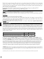
VM / VM RS / VMA / VMA RS / VM RS ACI /
VMA RS ACI /GV / GV ACI+ / CONCEPT
400 TC
B2
B2
B2/E2
B2/E2
B2/E2
B2/E2
B2/E2
G2
G2
G2
G2
G2
K2
K2
K2
K2
K2
VM TE / GV ACI TEC
PUISSANCE
/OUTPUT
W (BT)
VM TE 50/GV ACI TEC 50
VM TE 75/GV ACI TEC 75
VM TE 100/GV ACI TEC 100
VM TE 150/GV ACI TEC 150
VM TE 200 /GV ACI TEC 200
TENSION
VOLTAGE
(V)
1200/1800
1200/2400
1200/2400 220/240
V
1800/2400
2400/3000
5
5
5
5
5
9.2
9.2
9.2
9.2
9.2
230 400 TC
N
N
N
N
N
kW/
24H
Q 40°C
(l)
0,82
1,02
1,22
1,72
2,04
137
184
276
366
kW/
24H
Q 40°C
(l)
1,09
1,24
1,59
1,96
136
178
266
352
HM TE / GH ACI TEC
PUISSANCE
/OUTPUT
W (BT)
HM TE 75/GH ACI TEC 75
HM TE 100/GH ACI TEC 100
HM TE 150/GH ACI TEC 150
HM TE 200/GH ACI TEC 200
1200
1800
1800
2400
TENSION
VOLTAGE
(V)
220/240
V
8
8
8
8
9.3
9.3
9.3
9.3
230 400 TC
O
O
O
O
VS TE / GZT ACI TEC
PUISSANCE
/OUTPUT
W (BT)
VS TE 150/GZT ACI TEC 150
VS TE 200/GZT ACI TEC 200
VS TE 250/GZT ACI TEC 250
1800
2400
3000
VS TE 300/GZT ACI TEC 300
3000
TENSION
VOLTAGE
(V)
220/240
V
9,4
9,4
9,4
230
O
O
O
9,4
O
kW/
24H
Q 40°C
(l)
1,69
2,06
2,41
261
366
453
2,73
573
400 TC
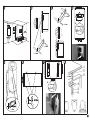
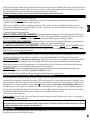
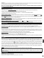
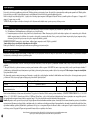
1
2
3
4
184
>= 6 mm
>= 6 mm
2X
>= 6 mm
>= 6 mm
>= 6 mm
6
5
7
8
>= 8mm
2X
>= 6 mm
>= 8mm
>= 8mm
5
91
9
92
1
9
93
94
1
8
7
8
2
3
5
4
1
1
5
8
2
6
7
8
2
3
4
3
5
2
6
7
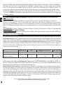
ES
Geurafsluiter
Waterdrukregelaar
(recommanded if pressure > 5 bar)
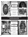
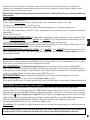
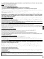
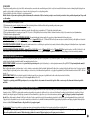
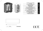
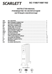
5- Stop valve
6- Drain to sewage
7- Cold water tube
8- Dielectric union
R
Afvoer
8- Verplichte diëlektrische
koppeling
7
3
4
6
1- Hot water tube
2- Safety relief valve
3- Funnel
4- Pressure reducing valve
5
6
4
RO
1- Iesire apa calde
2- Supapa de siguranta
3- Scurgere (plcurator)
4- Reductor de prestune
(pentru presiuni peste 5 bar)
5- Robinet
6- Tub golire
7- Intrare apa rece
8- Racord dielectric
HR
9. Only for Saudi Arabian :
to pressure relief valve
I
1-tubazione acqua calda
2-valvola di sicurezza
3-imbuto
6
4-valvola di riduzione pressione 7-tubazione acqua fredda
8-giunto dielettrico
e(se acquedotto > 5bar)
5-valvola di ritegno
6-scarico in fognatura
4. (
BL
5,5 )
1. 2. (
5.%*
6./e
3. 7. 8./
95
1
4
8
A1
B1
A2
B2
A3
C1
5
2
7
3
6
1
96
8
4 5
2
6
7
3
101
1
7
8
102
8
1
7
7
8
C2
E1
F2
D1
E2
G1
D2
F1
G2
H1
J1
L1
I1
K1
M1
K2
M2
A1
A2
A3
B1
B2
B3
1
2
5
3
I2
A1
A2
A3
B1
B2
B3
1
5
2
3
9
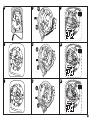
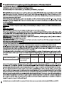
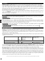
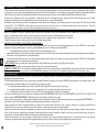
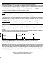
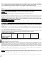
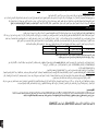
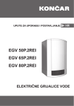
Borne de terre / Borna de tierra / Borne de terra
Filerie de l’ACI / Cables del ACI / Cabos do ACI
Voyant ACI / Piloto luminoso ACI /
Piloto luminoso do ACI
Bornier d’alimentation (non polarisé) /
Bornas de alimentación /
Bornes de alimentação
Filerie élément chauffant / Cables resistencia /
Cabos de resisténcia
Règlage de la température de l’eau / Ajuste de la temperatura del agua / Regulação de temperatura de água
Element chauffant / Resistencia / Resisténcia
Connecteur filerie élément chauffant /
Conector cables resistencia /
Ligador dos cabos da resisténcia
N
Sonde température / Sonda temperatura /
Sonda de temperature
N
EFFECTUER LE RACCORDEMENT DE L’ALIMENTATION SUR LE BORNIER UNIQUEMENT /
CONNECT THE POWER SUPPLY ONLY VIA THE TERMINAL /
DE STROOM ENKEL OP DE KLEMMENSTROOL ANSLUITEN
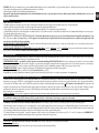
Borne de terre / Borna de tierra / Borne de terra
O
Element chauffant / Resistencia / Resisténcia
Sonde température / Sonda temperatura /
Sonda de temperature
Bornier d’alimentation (non polarisé) /
Bornas de alimentación /
Bornes de alimentação
Filerie élément chauffant / Cables resistencia /
Cabos de resisténcia
Connecteur filerie élément chauffant /
Conector cables resistencia /
Ligador dos cabos da resisténcia
Filerie de l’ACI / Cables del ACI / Cabos do ACI
Voyant ACI / Piloto luminoso ACI /
Piloto luminoso do ACI
Règlage de la température de l’eau / Ajuste de la temperatura del agua / Regulação de temperatura de água
10
O
11
Durée commerciale de garantie :
12
Gamme
Petites capacités 10 à 30 L
E-Series
Blindé ou O’pro hors 10 à 30 L
Garantie légale
2 ans toutes parties
2 ans toutes parties
2 ans toutes parties
Garantie commerciale supplémentaire
sur cuves et corps de chauffe,
+ 1 an
+1 an
+3 ans
hors composants électrique
Gamme Stéatite
2 ans toutes parties
+3 ans
WARNING : This device is not intended for use by persons (including children) with physical, sensory or mental disability, or by persons lacking experience or knowledge, unless they have received from a person in
charge of their safety adequate supervision or preliminary instructions on how to use the device.
Care must be taken at all times to keep children from playing with the device.
Important: The applicable national standards must be observed when installing the water heater . If you judge that you do not have sufficient expert knowledge to install this product correctly, you are
advised to consult a professional.
LOCATION
Caution : Heavy items – handle with care.
1°) Install the appliance in a room which is protected from frost. If the appliance is damaged because the safety device has been tampered with, it is not covered by the guarantee
2°) Make sure that the wall on which the appliance is mounted can support the weight of the appliance when filled with water
3°) If the appliance is to be fitted in a room or location where the ambient temperature is higher than 35°C, ventilation must be provided in the room
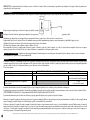
4°) When installed in a bathroom, do not install the appliance in volumes V0 and V1 (see fig 1). If the water heater is to be installed above habitable rooms, fit a retaining tank with drainage to the sewerage system.
5°) Position the appliance where it can be accessed.
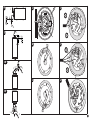
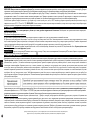
INSTALLATION OF A VERTICAL WALL-MOUNTED APPLIANCE: To enable the heating element to be replaced, leave free space below the ends of the tubes of the appliance. Small appliance: (see fig
2/3) ; Ø 438 range ( see fig 4); Ø 505 range: (See fig 5 ). Ø 505 appliances can be mounted on a tripod (optional) if the wall is not strong enough. It is, however, obligatory for the upper bracket of the
water heater to be attached to the wall to prevent it tilting.
INSTALLATION OF A STABLE WATER HEATER The water heater must be installed absolutely vertically in such a way as to ensure perfect stability with access to its electrical parts and safety devices.
Allow for access to parts which may need replacing.
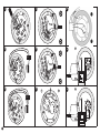
INSTALLATION OF A HORIZONTAL WATER HEATER: PC 30 and 50 l(Ø 338) Range: (see fig 6) ; Ø 433 range: (see fig 7) ; Ø 505 Range Various ways to install (see fig 8); when the water heater is
in place, the water connections MUST be absolutely vertical below the appliance. Allow for access to parts which may need replacing.
WATER CONNECTIONS
All water supply pipes must be thoroughly cleaned before connection. The connection to the hot water outlet must be made using a cast iron or steel sleeve or a dielectric union in order to avoid corrosion of the
tubes (due to direct contact between iron and copper). A brass union must not be used.
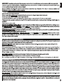
UNVENTED INSTALLATION: A new safety device which conforms to current standards (in Europe EN 1487) MUST be fitted. The safety valve must be protected from frost. No water accessory must be
located between the safety device and the cold water inlet to the appliance. A pressure reducer (not supplied) is required when the water supply pressure exceeds 5 bar. Connect the safety device to an outlet pipe to
drain off the heat-expanded water or to allow for drainage of the water heater. Pipes used must be capable of withstanding a temperature of 100 °C and a pressure of 10 bar (see fig 9 )
VENTED INSTALLATION: (Supply for a single water drawing point). The installation must be equipped with a special mixer tap (not supplied).
Attention : each time the unit heats up, water will flow from the tap. Do not block this flow. (see fig 10 )
If using PER pipes, we strongly recommend that a thermostatic regulator be fitted to the water heater outlet. It will be set according to the performances of the equipment used.
ELECTRICAL CONNECTIONS (table of diagrams. Refer to the relevant diagrams)
The water heater can be connected and powered only by a single-phase 220/240 V AC or a three-phase 400 V mains supply according to model. Connect the water heater via a fixed duct with a cross section of 2.5
mm2 (4 mm2 for power supply > 3700 W). Use a standard duct (fixed or ring reinforced sheath) to the calibrated receptacle in the caver. In the case of appliances fitted with a cable or a plug (not allowed in France),
connect up directly. The earthing conductor on the cable MUST be earthed or the wire must be earthed using the spike (shown by the symbol . ). This connection is a vital safety feature. The green-yellow earth
wire must be longer than the phase wires. The installation must be equipped, upstream of the appliance, with a bipolar cut-out device (contact opening at least 3 mm ; fuse, breaker switch.) If the ducts are made of
insulating material, the electrical contacts must be protected by a 30 mA earth-leakage breaker conforming to the applicable standards. Adapt the connection to the power supply (see diagrams and table).
Before removing the cover, switch off the power.
Thermal circuit breaker: All our products are equipped with a thermal circuit breaker with manual resetting which shuts off the power to the water heater if it becomes overheated.
Attention: If the circuit breaker keeps tripping. a) switch off the power before taking any further action, b) remove the caver, c) check the electrical connections, d) reset the thermal circuit breaker. If
the circuit breaker continues to trip, replace the thermostat. Never by-pass the safety device or the thermostat. Connect the power supply only via the terminal.
COMMISSIONING/USE
ATTENTION : Never switch the water heater on without it being filled with water. Before switching on, open the hot water taps, bleed the pipes until no air is present and fill the appliance.
Check that the pipes and the door seal under the caver are not leaking. If there are any leaks tighten gently. Check that the water safety devices are working and fill the appliance. Switch on the appliance. After 5 to
20 minutes according to the capacity of the appliance, water should start dripping from the drain outlet. This is normal and results from the expansion of the water. Check that joints and seals are watertight. In the
course of heating up, shielded water heaters may make a boiling noise ; this is normal and does not indicate any fault with the appliance.
To avoid the development of bacteria (legionella…) ensure that a temperature of 60°C is reached every day. The thermostat is set at the factory at (65°C+- 5°C. or 82+-3°C according to model). IMPORTANT: If
steam or boiling water emerges continuously from the drain plug or drain tap, switch off the electricity and call a professional.
MAINTENANCE
User maintenance: operate the drain valve on the safety device once a month. If this is not done, damage may be caused and the guarantee invalidated.
Maintenance by a qualified person:
a) Remove the scale sludge. Do not scrape or chip at lime scale deposited on the casing because this may damage the lining
13
b) Change the magnesium anode every 2 years or when its diameter is less than 10 mm. Changing the shielded heating element or the anode requires the water heater to be drained and the seal changed. Switch off
the power and cold water and open the hot water taps before carrying out these operations. Refit the heating element and tighten the screws gently (opposite screws in sequence), check for leaks the next day and
tighten if required.
REPLACEABLE PARTS: the thermostat, seals, heating element, boiler shell, the indicator light, the magnesium anode, the ACI plate, the connection cable. The guarantee requires genuine manufacturer’s
parts to be used.
ACI PRODUCTS (special instructions): Check that the ACI indicator light flashes for at least 15 minutes after the appliance is switched on. If the ACI indicator light does not flash, please contact your dealer.
SCOPE OF THE GUARANTEE
The water heater must be installed, used and maintained according to best practice and conform to the standards in force in the country in which it is installed and to the instructions contained in this document.
In the European Union this appliance is covered by the statutory guarantee accorded to consumers in accordance with directive 1999/44/CE. This guarantee comes into force when the appliance is delivered to the
consumer. In addition to the legal guarantee, certain items are covered by an extra guarantee relating only to the free exchange of the tank and of components accepted as defective. It does not include the cost of
replacement or carriage. Refer to the table below.
This commercial guarantee does not affect your statutory rights. It applies within the country where the product was acquired, provided it is also installed in the same country. The dealer must be informed of any
damage before the product is exchanged under guarantee and the appliance will remain available for inspection by experts from the insurance company and the manufacturer.
Range
10 to 30 L
Range
Small 10Small
to 30 L
Statutory guarantee
2 years all parts
Statutory
Extracommercial
commercialguarantee
guaranteeon on
tanks
and
Extra
tanks
and heating
+ 1 year
+ 1 year
heating elements, except for electrical
elements,
except for electrical components
(For Ireland : + 0 year)
components
E-Series E-Series
IMMERSION
ELEMENT,
ABOVE
30 L ranges
Shielded or O’pro
except 10 to 30
l
ACI
and Steatite
ACI and Steatite ranges
2 years all parts
+ 1 year
+ 3 years
(For Ireland : + 0 year)
+ 1 year
+ 3 years
+ 3 years (For Ireland : + 0 year)
+ 3 year
(For Ireland : + 0 year)
To claim under guarantee, contact your installer or dealer. If necessary, contact : ATL INTERNATIONAL Tel.:(33)146836000, Fax (33)146836001 58 av Gén. Leclerc 92340 Bourg-la-Reine (France) who will
inform you of what you should do. The guarantee applies only to examined products which are accepted as faulty by the company underwriting the guarantee. It is essential that products should be retained for
inspection by them.
Exclusions: Wear parts: magnesium anodes….Equipment which cannot be assessed (access difficult for repair, maintenance or assessment). Equipment exposed to abnormal environmental conditions : frost, bad
weather, water which is abnormally aggressive or outside drinking standards, electrical supply with large spikes. Equipment installed without observing current standards in the country of installation: the absence or
incorrect fitting of safety devices, abnormal corrosion due to incorrect water fitments (iron/copper contact), incorrect earthing, inadequate cable thickness, non observance of the connection drawings shown in these
instructions. Equipment not maintained in accordance with these instructions. Repairs or replacement of parts or components in the equipment not carried out or authorised by the company responsible for the
guarantee. Non-connection of the ACI device for equipment fitted with this equipment. Changing a component does not extend the life of the guarantee.
The products illustrated in these instructions may be modified at any time to reflect changes in manufacture and current norms. Equipment conforms to electromagnetic directives 2004/108/CEE and low voltage
2006/95/CEE.
CAUTION : To reduce the risk of excessive pressures and temperatures in this water heater, install temperature and pressure protective equipment supplied with the water heater (pressure relief devices). Install the valve into an
opening provided for this purpose in the water heater, and orient it or provide tubing so that any discharge from the valve will exit only within 15cm above or at any distance below the structural floor and cannot contact any live
electrical part. The discharge opening must not blocked or reduced in size under any circumstances.
14
WAARSCHUWING : Dit apparaat is niet geschikt om te worden gebruikt door personen (kinderen inbegrepen) met verminderde lichamelijke, zintuigelijke of geestelijke vermogens of door personen zonder ervaring
of kennis behalve in het geval zij door degene die voor hun veiligheid verantwoordelijk is, in het oog worden gehouden of vooraf de nodige instructies hebben gekregen met betrekking tot het gebruik van het apparaat.
De kinderen moeten in het oog gehouden worden om te voorkomen dat zij met het apparaat gaan spelen.
Belangrijk : De installatie van de boiler moet voldoen aan de nationale normen die van kracht zijn in het land van installatie. Als u van mening bent onvoldoende kennis te hebben
voor de installatie van dit product, is het raadzaam een vakman te raadplegen.
INSTALLATIE Opgelet : Zwaar product dat met zorg moet worden behandeld
1°) Installeer het toestel in een vorstvrije ruimte. De vernieling van het toestel door overdruk, te wijten aan de blokkering van de veiligheidsgroep valt buiten de garantie.
2°) Controleer vóór de bevestiging of de muur sterk genoeg is om het gewicht van het met water gevuld toestel te dragen.
3°) Als het toestel wordt opgesteld in een ruimte of op een plaats waar de omgevingstemperatuur constant meer dan 35°C bedraagt, is een ventilatiesysteem voor dit lokaal noodzakelijk.
4°) Dit product in de volumes V0 en V1 niet in een badkamer installeren (zie fig. 1). Een opvangbak voorzien met afvoer naar de riolering als de boiler boven een bewoonbare ruimte wordt
geïnstalleerd.
5°) Het toestel op een toegankelijke plaats installeren.
BEVESTIGING VAN EEN VERTICALE WANDBOILER : Om de eventuele vervanging van het verwarmingselement mogelijk te maken, onder de uiteinden van de buizen van het
toestel een ruimte vrijlaten. Gamma kleine modellen : (zie fig 2/3) ; gamma Ø 438 ( zie fig 4) ; gamma Ø 505 : (Zie fig 5) De toestellen Ø 505 kunnen op een (afzonderlijk te verkrijgen)
driepoot worden opgesteld als de muur niet voldoende stevig is. Het is evenwel verplicht om de bovenste bevestigingshaak in dat geval aan de muur te bevestigen om omkantelen te vermijden.
INSTALLATIE VAN EEN BOILER OP POOTJES De boiler moet perfect verticaal geïnstalleerd zijn zodat een perfecte stabiliteit is gewaarborgd, met toegang tot de elektrische delen en
de veiligheidselementen. Voor een toegang zorgen tot de elementen die mogelijk moeten worden vervangen.
BEVESTIGING VAN EEN HORIZONTALE BOILER : Gamma PC 30 en 50 l(Ø 338) : (zie fig 6) ; Gamma Ø 433 : (zie fig 7) ; Gamma Ø 505 Verschillende mogelijkheden voor de
installatie (zie fig 8); als de boiler eenmaal is geïnstalleerd, moeten de hydraulische aansluitingsbuizen zich verplicht in strikt verticale positie onder het apparaat bevinden. Voor een
toegang zorgen tot de elementen die mogelijk moeten worden vervangen.
HYDRAULISCHE AANSLUITING (Zie tabel met schema’s)
Vereist een grondige reiniging van de toevoerleidingen voor de hydraulische aansluiting. De aansluiting op de warmwaterafvoer moet gebeuren met behulp van een mof in gietijzer of staal, of
een diëlektrische aansluiting om corrosie van de leiding te vermijden (rechtstreeks contact ijzer/koper). Een aansluiting in messing is verboden.
MONTAGE ONDER DRUK : verplicht een nieuw veiligheidselement installeren op de warmwatertoevoer die de geldende normen respecteert (in Europa EN 1487). De veiligheidsgroep
moet tegen vorst beschermd worden. Er mag geen enkel hydraulisch toebehoren tussen het veiligheidselement en de koudwatertoevoer van het toestel worden geplaatst. Er is een reduceerventiel
nodig als de toevoerdruk hoger is dan 5 bar (niet meegeleverd). Het veiligheidselement aansluiten op een afvoerleiding om het dilatatiewater van de verwarming of het water bij een aftapping
van de boiler te evacueren. De leidingen moeten bestand zijn tegen 100 °C en 10 bar (zie fig 9).
DRUKLOZE MONTAGE : (Toevoer naar een enkel aftappunt) De installatie moet gebeuren met een speciale, niet meegeleverde, mengkraan.
Opgelet : bij elke opwarming ontsnapt er water op het niveau van de kraan ; het wegvloeien niet belemmeren. (zie fig 10)
Indien VPE-leidigen gebruikt worden, wordt de inbouw van een thermostaatregelaar aan de uitgang van de boiler van harte aanbevolen. Deze moet afgesteld worden aan de hand van de prestaties van het gebruikte material.
ELEKTRISCHE AANSLUITING( zie tabel met schema's - cfr de overeenkomstige schema's)
De boiler mag enkel aangesloten worden en werken op een netwerk met alternatieve stroom 220/240 V monofase of 400 V driefase volgens het model. De boiler aansluiten met een stevige
conductorkabel met een sectie van 2,5 mm2 (4 mm2 voor een vermogen > 3700 W).Gebruik hiervoor een genormaliseerde leiding (vaste of geribbelde koker) tot de gekalibreerde behuizing
- verplicht aansluiten, of de aarddraad
van de kap. De toestellen die voorzien zijn van een kabel of een stekker (verboden in Frankrijk), rechtstreeks aansluiten. De conductor van de aardkabel
terugbrengen naar de daartoe voorziene klem die gekenmerkt is met het symbool . Deze aansluiting is om veiligheidsredenen verplicht. De groen gele aarddraad moet een lengte hebben
die groter is dan deze van de fasen. De installatie moet stroomopwaarts van de boiler, een omnipolige verbrekingsinrichting hebben (opening contacten van minimum 3 mm : zekering,
stroomonderbreker.) .In het geval de hydraulische kanalisaties in isolerend materiaal zouden zijn, moeten de elektrische circuits beschermd worden met een differentieelschakelaar van 30 mA
die aan de geldende normen voldoet. De aansluiting op het stroomnet aanpassen (zie schema's en tabellen).
De stroom verbreken voor gelijk welke werkzaamheid. De kap afnemen
Verbreking warmtekring : Al onze producten zijn voorzien van een thermostaat met een verbreking van de warmtekring met manuele herinschakeling, die de stroomvoorziening van de
verwarming onderbreekt in geval van oververhitting.
Opgelet : Indien de zekering opspringt. a) de stroom verbreken voor gelijk welke werkzaamheid, b) de kap afnemen, c) de elektrische aansluiting controleren, d) de verbreking
van de thermische kring opheffen. Indien de zekering herhaaldelijk springt, overgaan tot de vervanging van de thermostaat. De veiligheid of de thermostaat nooit kortsluiten. De
stroom enkel op de klemmenstrook aansluiten.
INDIENSTSTELLING/WERKIN
OPGELET De boiler nooit onder spanning zetten zonder water. Voor u hem onder spanning zet, de warmwaterkranen openen, de leidingen ontluchten tot er geen lucht meer aanwezig is
en het apparaat vullen.
De dichtheid van de buizen en van de voeg van de deur onder de kap controleren. Bij een lek matig aantrekken. De werking van de hydraulische veiligheidselementen controleren en vullen.
15
Het toestel onder spanning zetten. Na 5 tot 20 minuten, volgens de capaciteit van het toestel, moet het water druppelsgewijs langs de aftapopening wegvloeien. Dit fenomeen is normaal te
wijten aan de dilatatie van het water. De dichtheid van de aansluitingen en van de voeg controleren. Tijdens het verwarmen en volgens de kwaliteiten van het water, kunnen de geblindeerde
boilers een kokend geluid maken. Dit geluid is normaal en wijst niet op een defect van het toestel.
Om de ontwikkeling van bacteriën (legionella) te vermijden, minstens één verwarming per dag op 60°C waarborgen. De thermostaat is in de fabriek voorgeregeld (65°C+- 5°C. of 82+-3°C
volgens het model). BELANGRIJK : Als vastgesteld wordt dat er een constante ontsnapping is van damp of van kokend water langs de aftap of langs de opening van een aftapkraan, de
elektrische stroomvoorziening van de boiler onderbreken en een vakman raadplegen.
ONDERHOUD.
Huishoudelijk onderhoud : Het aftapelement van de hydraulische veiligheid 1 keer per maand manoeuvreren. De niet-naleving van dit onderhoud kan de werking nadelig beïnvloeden of
kan leiden tot het verlies van de garantie.
Onderhoud door een gekwalificeerde persoon :
a) De aanzetting in de vorm van slib verwijderen. De aanzettingen op de wand niet afkrabben of afkloppen aangezien dit de bekleding zou kunnen beschadigen.
b) De magnesiumanode om de 2 jaar vervangen of zodra de diameter minder dan 10 mm bedraagt. Om het geblindeerd verwarmingselement of de anode te vervangen, moet de boiler geleegd
worden en moet de dichting vervangen worden. De elektrische stroomvoorziening en de koudwatertoevoer onderbreken en de warmwaterkranen openen alvorens deze werkzaamheden uit te
voeren. Het verwarmingselement terug monteren door de moeren redelijk aan te trekken (gekruiste aantrekking). De dichtheid de volgende dag controleren en indien nodig aantrekken.
VERVANGBARE STUKKEN : de thermostaat, de dichtingen, het verwarmingselement, het verwarmingslichaam, de lichtdiode, de magnesiumanode, de ACI-kaart, de aansluitingskabel. De
garantie is afhankelijk van het gebruik van originele stukken van de constructeur.
ACI-PRODUCTEN (specifieke producten) : Controleren of de ACI-led minstens 15 minuten nadat de boiler onder spanning gezet wordt, begint te knipperen. Als de ACI-led niet knippert,
gelieve dan uw verdeler te contacteren. (de batterij niet wegwerpen)
TOEPASSINGSVELD VAN DE GARANTIE
De boiler moet geïnstalleerd, gebruikt en onderhouden worden volgens de regels van de kunst, overeenkomstig de normen die van kracht zijn in het land waar hij wordt geïnstalleerd en
volgens de instructies van deze handleiding.
In de Europese Unie geniet van de wettelijke garantie, toegekend aan de gebruikers in toepassing van de richtlijn 1999/44/CE, deze garantie begint te lopen op de datum van de levering
aan de gebruiker.
Temeer van de wettelijke garantie genieten sommige produkten van een bijkomende garantie op de gratis omruiling van de kuipen en de bestanddelen die als defect erkend worden ; exclusief
de vervanging en portkosten. Zie tabel hieronder.
De bepalingen van deze garantievoorwaarden sluiten het voordeel ten gunste van de koper de wettelijke garantie niet uit. De waarborg is van toepassing in het land waar het toestel wordt afgeschaft,
op voorwaarde dat deze in hetzelfde land wordt geplaatst.
Elk schadegeval moet aan depositaris worden aangegeven voor omruiling onder garantie en het toestel zal ter beschikking blijven van de deskundigen van de verzekering en van de constructeur.
Duur van de commerciële garantie
commerciale de garantie
Gamma
Kleine modellen 10 tot 30 L
E-Series
Geblindeerd of O’pro exel 10 à 30 L
Gamma ACI
Wettelijke waarborg
2 jaar op alle onderdelen 2 jaar op alle onderdelen
2 jaar op alle onderdelen
2 jaar op alle onderdelen
Bijkomende commerciële waarborg
op kuip en verwarmingslichaam,
+1 jaar
+1 jaar
+3 jaar
+3 jaar
exclusief electrisch bestanddeel
De vervanging van een onderdeel geeft geen aanleiding tot een verlenging van de garantie op het toestel. Om de garantie te genieten, neemt u contact op met uw installateur of verdeler. Bij
ontstentenis hiervan, neemt u contact op met : ATL – Avenue Château Jaco 1 – 1410 WATERLOO – Belgique - Tel : 0080038713858 (België) waar men u zal meedelen welke stappen u moet volgen.
De garantie zal enkel van toepassing zijn op producten die aan een expertise werden onderworpen, of als defect worden erkend door de garantieverstrekkende onderneming. Het is noodzakelijk
om de producten ter beschikking van deze laatste te houden.
Zijn uitgesloten van de garantie : De slijtstukken: magnesiumanode.... De toestellen die niet aan een expertise kunnen worden onderworpen (moeilijk voor reparatie, onderhoud of expertise
toegankelijke toestellen). De toestellen die worden blootgesteld aan abnormale omgevingsvoorwaarden : vorst, slechte weersomstandigheden, water met abnormaal agressieve eigenschappen
buiten de drinkbaarheidscriteria, elektrische stroomvoorziening met grote overspanningen. De toestellen die worden geïnstalleerd zonder de normen en reglementeringen te respecteren die in
het land van installatie van kracht zijn : afwezigheid of slechte montage van veiligheidselementen tegen overdruk, abnormale corrosie te wijten aan een onjuiste hydraulische aansluiting
(contact ijzer/koper), onjuiste aarding, onvoldoende sectie van de elektrische kabel, niet-naleving van de aansluitingsschema's die in deze handleiding worden verstrekt. De toestellen die niet
werden onderhouden conform de voorschriften van deze handleiding. De reparaties of vervangingen van stukken of bestanddelen van het toestel die niet uitgevoerd of toegestaan werden door
de garantieverstrekkende onderneming. Ontbrekende aansluiting van de ACI-inrichting voor toestellen die daarmee zijn uitgerust. De vervanging van een onderdeel geeft geen aanleiding tot
een verlenging van de garantie op het toestel.
16
De producten die in deze handleiding worden voorgesteld, kunnen op gelijk welk moment worden gewijzigd om tegemoet te komen aan de evolutie van de technieken en de geldende normen. Toestellen conform de elektromagnetische richtlijn 2004/108/CEE en de
laagspanningsrichtlijn 2006/95/CEE.
Das Gerät ist nicht dafür bestimmt, von Kindern und von Personen mit eingeschränkten körperlichen, sensorischen oder geistigen Fähigkeiten benutzt zu werden. Das gleiche gilt für Personen, die
keine Erfahrung und keine Kenntnisse im Gebrauch des Geräts besitzen, es sei denn, sie werden von einer für ihre Sicherheit verantwortlichen Person beaufsichtigt oder haben von derselben im
Vorfeld Anweisungen zum Gebrauch des Geräts erhalten. Kinder sind zu beaufsichtigen, damit sie nicht mit dem Gerät spielen.
Wichtig: Bei der Installierung des Warmwasserbereiters müssen die im Lande der Installierung geltenden Normen beachtet werden.
Installation
Bitte beachten Sie: Schwere Produkte sollten mit Vorsicht gehandhabt werden.
1°) Der Apparat sollte an einem frostfreien Ort installiert werden. Bei Zerstörung des Apparates durch Überdruck unter Blockieren des Sicherheitselements besteht keine Garantie.
2°) Prüfen Sie, ob die Trennwand das Gewicht des mit Wasser gefüllten Apparats trägt.
3°) Falls der Apparat an einem Ort oder einem Platz, dessen Normaltemperatur ständig über 35°C liegt, installiert werden soll, muss eine Belüftung für diesen Ort vorgesehen werden.
4°) Dieser Apparat darf im Badezimmer nicht an den Bereichen V0 und V1 (siehe Abb. 1) angeschlossen werden. Sehen Sie ein Auffangbecken mit Ablauf zum Abfluß vor, falls der
Wärmeaufbereiter in einer Wohnung eingebaut werden soll
5°) Installieren Sie den Apparat an einem zugänglichen Ort.
VERTIKALE WANDMONTAGE EINES WARMWASSERBEREITERS°: Um den Austausch des Heizelements zu ermöglichen, lassen Sie einen Freiraum unterhalb der Rohrenden des
Warmwasserbereiters. (siehe Abb. 2/3)…Serie Ø 438 (siehe Abb. 4)… Serie Ø 505 . (Siehe Abb. 5) Die Apparate Ø 505 können auf einem Dreifuß (optional) aufgebaut werden, falls die
Wand nicht ausreichend dick ist. Die obere Halterung des Warmwasserbereiters muss jedoch unbedingt an der Wand befestigt werden, um ein Kippen zu verhindern.
EINBAU EINES SICHEREN WARMWASSERBEREITERS Der Warmwasserbereiter muss absolut senkrecht und so, dass eine perfekte Stabilität garantiert ist eingebaut werden. Zudem
müssen die elektrischen Teile und die Sicherheitselemente zugänglich sein. Sichern Sie den Zugang zu den eventuell auszutauschenden Elementen.
WAAGERECHTE WANDMONTAGE EINES WARMWASSERBEREITERS°: Serie PC 30 und 50 l(Ø 338) : (siehe Abb. 6) Serie Ø 433 : (siehe Abb. 7) Serie Ø 505 Verschiedene
Einbaumöglichkeiten (siehe Abb.8). Nach Installation des Warmwasserbereiters müssen die hydraulischen Anschlussrohre sich unbedingt senkrecht unterhalb des Apparates befinden.
Sichern Sie den Zugang zu den eventuell auszutauschenden Elementen.
HYDRAULISCHE ANSCHLÜSSE
Die Versorgungsleitungen müssen vor dem hydraulischen Anschluss gut gereinigt werden. Der Anschluss des Warmwasserabflusses ist mit einer Gewindemuffe aus Gusseisen, Stahl oder
einem nicht leitenden Verbindungsstück gefertigt, um die Korrosion der Gewinde zu verhindern (direkter Kontakt Eisen/Kupfer). Ein Verbindungsstück aus Messing ist untersagt.
MONTAGE DRUCKBETRIEB: Bauen Sie unbedingt eine neue Sicherheitsgruppe am Eingang des Warmwasserbereiters ein, welche den gültigen Normen entspricht (in Europa: EN 1487).
Der Sicherheitsgruppe muss vor Frost geschützt warden. Zwischen der Sicherheitsgruppe und dem Kaltwasserzugang des Apparats darf sich kein hydraulisches Zubehör befinden. Ein
Druckregelventil muss vorhanden sein, wenn der Versorgungsdruck mehr als 5 bar beträgt (nicht geliefert). Schließen Sie die Sicherheitsgrupe an eine Ablassleitung an, um überschüssiges
Wasser während der Aufheizung oder, im Falle der Entleerung des Warmwasserbereiters, Wasser ableiten zu können.
MONTAGE DRUCKLOS : (Versorgung eines einzigen Entnahmehahns) Die Installation muss mit einem speziellen, nicht in der Lieferung inbegriffenen Mischhahn vorgenommen werden.
Vorsicht: Bei jedem Aufheizen erfolgt ein Ablauf am Hahn, verstopfen Sie diesen Ablauf nicht. (siehe Abb. 10)
Anschluss : Falls Sie Kunstoffröhre benutzen (PER), achten Sie darauf ein thermoregulator anzuwenden. Dieser wird je nach kunstoff angepasst.
ELEKTRISCHER ANSCHLUSS (siehe, Tabelle der Schemen… schauen Sie … im entsprechenden Schema nach).
Der Warmwasserbereiter kann je nach Modell nur mit Wechselstrom 220/240 V einphasig oder 400 V dreiphasig angeschlossen werden und funktionieren. Schliessen Sie den Apparat mit
einem starren Kabel mit Leiterquerschnitt 2,5 mm2 (4 mm2 bei einer Leistung > 3700 W) an. Dazu verwenden Sie eine genormte Leitung (mit starrem Kabel oder Kabelkanal) bis zum
entsprechenden Gehäuse des Deckels. Falls die Apparate ein Kabel oder einen Stecker besitzen (in Frankreich verboten), können Sie diese direkt anschließen. Verbinden Sie sofort die
Erdleitung mit der Erde oder befestigen Sie das Erdkabel an den durch das Symbol… gekennzeichneten Schaltstecker. Dieser Anschluss ist aus Sicherheitsgründen unerlässlich. Das grüngelbe Erdkabel muss länger als die der Phasen sein. Die Installation sollte zusätzlich zu dem Warmwasserbereiter eine Vorrichtung der omnipolaren Trennung (Kontaktöffnung von
mindestens 3 mm, Sicherung, Erdungsschalter) enthalten. Falls die Wasserleitungen aus isolierendem Material bestehen, sind die elektrischen Kreise durch einen den gültigen Normen
angepassten Fehlerstromschutzschalter 30 mA zu schützen. Passen Sie den Anschluss an den Versorgungsdruck an (siehe Schemas und Tabelle).
Vor Abbau des Deckels, schalten Sie den Strom aus.
Thermische Sicherung°: Alle unsere Produkte sind mit einem Thermostat mit thermischer Sicherung und manueller Rückstellung ausgestattet, welches die Stromversorgung des
Warmwasserbereiters im Falle von Überhitzen unterbricht.
Bitte beachten: Falls die Sicherheitsabschaltung ausgelöst wird. a) schalten Sie den Strom vor jeder Arbeit ab, b) nehmen Sie den Deckel ab c) überprüfen Sie den
Elektroanschluss.d)stellen Sie die thermische Sicherung zurück. Bei mehrfachem Auslösen tauschen Sie das Thermostat aus. Schließen Sie niemals die Sicherung oder das Thermostat
kurz. Führen Sie den Anschluss der Stromversorgung nur an der Anschlussleiste aus.
ANSCHLUSS / BETRIEB
BITTE BEACHTEN: Setzten Sie den Warmwasserbereiter niemals ohne Wasser unter Strom. Bevor Sie ihn unter Strom setzen, öffnen Sie die Warmwasserhähne und entlüften Sie die
Leitungen bis keine Luft mehr darin ist. Damit befüllen Sie den Apparat.
17
Überprüfen Sie die Dichtheit der Rohre und der Flanschdichtung unterhalb des Deckels. Bei Leckage ziehen Sie die Schrauben des Flansch leicht an. Überprüfen Sie das Funktionieren der
Sicherheitsgruppe und des Ablaufs. Setzen Sie den Apparat unter Strom. Nach 5 bis 20 Minuten, je nach Kapazität des Apparats, sollte das Wasser tropfenweise durch die Ablauföffnung
ablaufen. Dies geschieht aufgrund der Wasserausdehnung. Überprüfen Sie die Dichtheit der Anschlüsse und der Flanschdichtung. Während des Erhitzens und abhängig von der
Wasserqualität können die Warmwasserbereiter mit Tauchheizkörper ein Geräusch wie kochendes Wasser machen, dies ist normal und kennzeichnet keinesfalls einen Fehler des Apparats.
Um das Entwickeln von Bakterien zu verhindern (Legionella), sollte der Apparat einmal täglich auf 60°C erhitzt werden. Der Thermostats ist im Werk eingestellt (65°C +/- 5°C oder 82 +/3°C je nach Modell). WICHTIG: Bei ständigem Entweichen von Dampf oder kochendem Wasser durch den Ablauf oder durch das Öffnen eines Zapfhahns schalten Sie die Stromversorgung
ab und fragen Sie einen Fachmann
WARTUNG
Pflege: Betätigen Sie 1 Mal monatlich die Abflusshebel der Sicherheitsgruppe. Das Nichtbefolgen dieser Pflege kann eine Lebensdauerverkürzung und den Garantieverlust mit sich bringen.
Pflege durch geschultes Personal :
a) Entfernen Sie den in Form von Schlamm abgelagerten Kalk. Kratzen oder klopfen Sie nicht den auf der Wand abgelagerten Kalk; die Beschichtung könnte beschädigt werden.
b) Tauschen Sie die Magnesiumanode alle 2 Jahre oder wenn ihr Umfang weniger als 10mm beträgt, aus. Bei Austausch des Tauchheizelements oder der Anode muss der
Warmwasserbereiter entleert und die Dichtung ausgewechselt werden. Stellen Sie den elektrischen Strom und das Kaltwasser ab, öffnen Sie die Warmwasserhähne vor Beginn der Arbeiten.
Montieren Sie das Heizelement wieder, ziehen Sie die Schrauben soweit wie nötig an (Kreuzdrehen), kontrollieren Sie am nächsten Tag die Dichtheit und ziehen Sie die Schrauben nach falls
nötig nach.
AUSTAUSCHELEMENTE: Das Thermostat, die Dichtungen, das Heizelement, der Heizkörper, die Anzeigelampe, die Magnesiumanode, die ACI Platine, das Verlängerungskabel. Die
Garantie ist auf die vom Hersteller stammenden Teile beschränkt.
Die ACI-Produkte … (Besonderheiten): Prüfen Sie, ob das ACI-Lichtsignal spätestens 15 Minuten, nachdem der Apparat unter Druck gesetzt worden ist, blinkt. Falls das ACI-Lichtsignal
nicht blinkt, nehmen Sie bitte Kontakt mit dem Verkäufer auf.
ANWENDUNGSBEREICH DER GARANTIE
Der Warmwasserbereiter muss nach den Regeln der Kunst installiert, gebraucht und gepflegt werden, entsprechend der im Land des Einbaus gültigen Normen und den Angaben dieser
Notiz..In der Europäischen Union steht dieser Apparat unter gesetzlicher Garantie, die den Verbrauchern durch die Richtlinie 1999/44/CE zuerkannt wird. Diese Garantie beginnt mit der
Übergabe der Ware an den Endverbraucher. Zusätzlich zu der gesetzlichen Garantie erhalten einige Produkte eine Garantie, welche sich ausschließlich auf den kostenlosen Austausch des
Innenbehälters und der als defekt erkannten Teile beschränkt, mit Ausnahme der Kosten für den Austausch und der Portokosten. Siehe unten stehende Tabelle .Diese Verkaufsgarantie
betrifft in keiner Weise die Ihnen nach Anwendung der legalen Garantie zustehenden Rechte. Sie wird für die Länder, in denen das Produkt gekauft wurde, angewendet, vorausgesetzt, die
Ware wurde in diesem Land eingebaut. Jeder Defekt muss dem Verkäufer vor einem Austausch unter Garantie angegeben werden; in diesem Fall muss das Gerät den Versicherungs- und
Herstellerexperten zur Verfügung gestellt werden.
Serie
Rechtliche Garantie
Zusätzliche Verkaufsgrarantie auf Behälter
und Heizkörper, ohne Elektroteile
Kleinspeicher 10 bis 30 L
E-Serie
+ 1 Jahr
+ 1 Jahr
Tauchheizkörper oder mehr als 10 bis 30 l
2 Jahre auf alle Teile
+ 3 Jahre
ACI und “Ceramic” Range
+ 3 Jahre
Zur Geltendmachung der Garantie kontaktieren Sie Ihren Installateur oder Verkäufer. Anderenfalls :ATLANTIC INTERNATIONAL:Tél.:(33)146836000, Fax (33)146836001. 58 av
Gén. Leclerc, 92340 Bourg-la-Reine (Frankreich), die Ihnen weiterhelfen können. Die Garantie kann nur auf Teile, die von der für die Garantie zuständigen Firma überprüft und als defekt
anerkannt sind, angewendet werden. Die Teile müssen dieser Gesellschaft zur Verfügung gestellt werden.
Folgende Teile sind von der Garantie augeschlossen : Verbrauchst : Magnesiumanode…Nicht prüfende Teile (für die Reparatur, die Pflege oder die Expertise unzugänglich), Apparate die
nicht normalen Umweltbedingungen ausgesetzt sind :Frost, Unwetter, Wasser mit unnormaler Agressivität außerhalb der Trinkwassernormen, Wasserversorgung mit großem Überdruck.
Apparate die nicht unter Berücksichtigung der im Lande der Installation gültigen Normen und Vorschriften eingebaut wurden. Nicht vorhandene oder schlechte Montage der
Sicherungsgruppe zum Schutz gegen Überdruck, unnormale Korrosion durch falschen hydraulischen Anschluss (Kontakt Eisen/Kupfer), falsche Erdverbindung, unzureichender Querschnitt
des Elektrokabels, keine Berücksichtigung der Anschlussvorgaben aus dieser Notiz. Apparate, die nicht nach Vorgaben der vorliegenden Notiz gepflegt wurden, nicht vorgenommene oder
von der für die Garantie zuständige Firma nicht autorisierte Reparaturen oder Austausch von Teilen oder Bauelemente. Für Geräte mit dieser Ausstattung: nicht angeschlossene ACIVorrichtung. Der Austausch eines Elements verlängert nicht die Garantiedauer des Apparates.
Die in dieser Notiz erklärten Produkte können jederzeit geändert werden, um dem Fortschritt der Technik und den gültigen Normen zu entsprechen.
Die Apparate entsprechen den Richtlinien der Elektromagnetik 2004/108/CEE und Niederspannung 2006/95/CEE.
18
Importante: El buen funcionamiento de este Termo no depende únicamente de su calidad o la de sus componentes, es fundamental también una correcta instalación y mantenimiento, realizados por un profesional
cualificado.
Este aparato no está previsto para su uso por personas (incluidos los niños) cuyas capacidades físicas, sensoriales o mentales estén reducidas, o por personas sin experiencia ni conocimientos, salvo si han recibido la
supervisión o las instrucciones previas relativas al uso del aparato por parte de una persona responsable de su seguridad. Es conveniente mantener vigilados a los niños de manera que no jueguen con el aparato.
INSTALACIÓN
Advertencia: La instalación del termo debe realizarse por personal cualificado y cumplir con la reglamentación vigente, el Reglamento Electrotécnico de Baja Tensión, las Normas Básicas de Instalaciones Interiores de
Suministro de Agua, y cualquier otra reglamentación local, autonómica o nacional aplicable.
Le recomendamos tome precauciones debido al peso de los productos, la pared donde se instale el termo deberá soportar el peso del equipo una vez lleno de agua.
1°) Instale el aparato y su grupo de securidad en un lugar protegido de las heladas. La garantía no cubre los daños ocasionados por el exceso de presión que pueda causar el bloqueo del dispositivo de seguridad.
2°) Asegúrese de que la pared soporte el peso del aparato lleno de agua.
3°) Prevea la ventilación del local en el que se encuentra su aparato si la temperatura ambiente permanente es superior a los 35° C.
4°) No instale el termo dentro del volumen o el en un cuarto de baño (Véase Fig.1).
5°) Instale el aparato en un lugar de fácil acceso.
FIJACIÓN DE UN TERMO VERTICAL MURAL: El termo debe instalarse lo más cerca posible del punto de utilización para evitar perdidas de temperatura en las tuberías, y con las conexiones de agua abajo.
Con el fin de facilitar en su día la revisión, limpieza interior, y si fuera necesario la sustitución del elemento calefactor, prever un espacio libre debajo de los conductos de entrada y salida de agua como mínimo de 300 mm.
Gama de pequeña capacidad (véase Fig.2,3) ; Gama Ø 438 (véase Fig.4) ; Gama Ø 505 (véase Fig.5): la gama Ø 505 permite la instalación sobre trípode en caso de que la pared no sea muy resistente. Sin embargo, el
anclaje superior del calentador deberá estar obligatoriamente fijado a la pared para evitar cualquier riesgo.
COLOCACIÓN ESTABLE DEL CALENTADOR: deberá instalar el calentador únicamente en posición vertical y de forma que ofrezca un fácil acceso tanto a los dispositivos eléctricos como a los de seguridad.
Prevea el acceso a los elementos susceptibles de ser remplazados.
FIJACIÓN DE UN TERMO HORIZONTAL: Gama pequeña capacidad 30 y 50L (Ø 338); (véase Fig.6) Gama Ø 433; (véase Fig.7) La gama Ø 505 ofrece diferentes posibilidades (véase Fig.8). Una vez colocado el
calentador asegúrese que las cañerías de conexión hidráulica se encuentran en posición estrictamente vertical bajo el aparato. Prevea el acceso a los elementos susceptibles de ser remplazados.
CONEXIÓN HIDRAULICA (Véase tablas)
Limpie a fondo las tuberías de alimentación antes de realizar la conexión hidráulica con el fin de evitar que puedan introducirse partículas metálicas o extrañas en el termo. No emplee tubería o accesorios de cobre o
latón en contacto con de hierro o acero, en el sentido de la circulación del agua afín de evitar pares galvánicos y su efecto corrosivo. Conecte los manguitos dieléctricos, incluidos en el suministro del termo, a los tubos
de entrada y salida de agua.
MONTAJE CON PRESIÓN: Instale obligatoriamente sobre la entrada de agua fría al calentador, la válvula de seguridad suministrada con el termo. Esta válvula contiene una válvula de retención y de sobrepresión
conforme a la normativa en vigor, no sitúe ningún elemento de corte entre el dispositivo de seguridad y el termo. Instale un reductor de presión (no suministrado) a la entrada de la vivienda, si la presión en la instalación
de agua es superior a 5 bar.
La instalación de válvulas antirretorno en las acometidas de la red de agua sanitaria, ocasiona un fuerte aumento de presión en el interior de su termo por efecto del proceso de calentamiento, en consecuencia la válvula
de seguridad deberá evacuar agua con el fin de evitar una sobrepresión en el interior de la cuba, por lo que resulta imprescindible conducir el desagüe de esta válvula a un tubo de evacuación provisto de sifón, de forma
que se garantice que el agua caliente evacuada del interior de la cuba, no produzca daños a personas o cosas. El tubo de evacuación debe salir al aire libre e instalarse con pendiente hacia abajo (véase Fig.9).
MONTAJE SIN PRESIÓN : (Alimentación de un único punto de extracción). Para este tipo de instalación es necesario un grifo mezclador especial (no incluido).
Atención : No obstruya el goteo que se produce a nivel del grifo en todos los procesos de calentamiento (véase Fig.10).
CONEXIÓN ELÉCTRICA (Véase tablas pág. 2 y 3).
CONEXIÓN ELÉCTRICA (Véase tablas)
Asegúrese de que la tensión eléctrica disponible es de 220-230 V / 50 Hz. El cable de conexión del termo tiene una clavija tipo europeo, Schuko, con toma de tierra lateral. Asegúrese que la toma de corriente es una
base de enchufe adecuada para la clavija del termo (Base de enchufe tipo europeo, con toma de tierra lateral) y que los tres conductores (uno de ellos de tierra) hasta la base del enchufe tengan una sección mínima de
2,5 mm2 (4 mm2 para potencias >3.700W). Es necesario que la instalación del calentador cuente con un interruptor de corte omnipolar (apertura de los contactos de 3 mm. mínimo: fusible, disyuntor). En caso de que
las canalizaciones sean de material aislante, los circuitos eléctricos estarán protegidos por un disyuntor diferencial de 30mA conforme a las normas vigentes. Adapte la conexión a la tensión de la alimentación. (Véase
tablas pág 2/3). Ante todo desmontaje del zapatero, asegurarse que la alimentación es cortada
Termostato de seguridad: Todos nuestros productos están equipados con un termostato de seguridad de rearme manual que corta la alimentación del calentador en caso de sobrecalentamiento.
Atención: En caso de activación del dispositivo de seguridad contacte con el Servicio de Asistencia Técnica para que proceda a rearmar el termostato (Intervención no cubierta por la garantía). Se deberá proceder a
la sustitución del termostato en caso de activación repetitiva. No cortocircuitar nunca el termostato o el dispositivo de seguridad. Conectar los cables de alimentación únicamente sobre la caja de conexión.
MIENTO Y PUESTA EN MARCHA
ADVERTENCIA: No conecte el calentador vacío. Llene el termo de agua, abriendo la llave de corte del agua fría y los grifos de agua caliente, cuando salga agua por ellos, ciérrelos, empezando por el mas bajo (bidet)
y terminando por el más alto (ducha), de esta forma se eliminará el aire del termo y de las tuberías. Verifique la estanqueidad de las tuberías y del termo. En caso de fuga, apriete ligeramente. Compruebe el
funcionamiento de los dispositivos de seguridad de llenado y de vaciado. Conecte el termo enchufando su clavija a la red. Entre 5 y 20 minutos más tarde, según la capacidad del aparato, el agua goteará por el orificio
de descarga de la válvula de seguridad. Este fenómeno se debe a la dilatación del agua explicada en el apartado CONEXIÓN HIDRAULICA (Los calentadores blindados pueden producir un ruido de ebullición
durante el calentamiento en función de la calidad del agua, este ruido no se debe a ningún tipo de defecto).
Para evitar la proliferación de bacterias tales como la legionela, los límites del termostato vienen fijados de fábrica, (65°C ± 5°C).
19
IMPORTANTE: Corte la alimentación eléctrica del calentador y contacte con el Servicio de Asistencia Técnica si constata una fuga de agua hirviendo por el dispositivo de descarga de la válvula de seguridad o tras la
apertura del grifo de salida de agua caliente.
MANTENIMIENTO
MANTENIMIENTO
Mantenimiento por el usuario: Accione al menos una vez al mes el dispositivo de la válvula de seguridad (palanca 1) para el vaciado del agua del termo, a fin de evitar que se bloquee.
El ignorar está operación podría provocar el deterioro del aparato y la pérdida de la garantía.
Para limpiar el exterior del termo debe emplearse un paño humedecido con agua jabonosa, no emplee productos abrasivos o que contengan disolventes (por ejemplo alcohol).
Mantenimiento especializado: Ante todo desmontaje del zapatero o manipulación del termo, asegúrese de que se ha desconectado de la corriente eléctrica.
Es imprescindible que el Servicio de Asistencia Técnica, revise anualmente su termo para realizar el mantenimiento que garantice su correcto funcionamiento y la durabilidad del equipo tales como:
a) Eliminar la cal depositada en el elemento calefactor sin frotar la cuba para evitar el deterioro del revestimiento.
b) Cambiar el ánodo de magnesio cuando su diámetro sea inferior a 10 mm. o cada 2 años.
Piezas reemplazables: Por razones de seguridad cuando el termostato, las juntas, el elemento de calefacción, el ánodo de magnesio, y/o el cable de conexión, deban ser reemplazados, debe hacerse con repuestos
originales y por nuestro Servicio de Asistencia Técnica, de lo contrario el fabricante no se responsabiliza de los daños que se puedan ocasionar.
PRODUCTOS ANTICORROSION : Compruebe que el piloto anticorrosión funcione 15 minutos después de la conexión del aparato como máximo. Si el piloto no funcione, contacte con el servicio de asistentia
técnica (intermitente o bijo segun modelo). (No tirar el acumulator ACI)
GARANTÍ
GARANTIA
La instalación, la utilización y el mantenimiento del termo deben ser conformes a las normas nacionales en vigor y a las instrucciones dadas en este manual. Según la directiva 1999/44/CE, este aparato otorga al
consumidor una garantía legal efectiva, aplicable exclusivamente en la UE, a partir de la fecha de compra del producto. Además de la garantía legal, algunos de nuestros productos ofrecen una garantía suplementaria
que cubre el cambio de la cuba y de los componentes defectuosos, pero no cubre la mano de obra ni el desplazamiento.
Véase el cuadro siguiente.
Garantía legal (España)
Garantía comercial suplementaria sobre la cuba (España)
Concept GB, GH, GZT 500, GP+, GTS+, GH+, IAV, JAM, PC, PC HM, VM, HM, VS
2 años de garantía total
+ 3 años (+1 año en las Islas canaries)
Garantiá commercial suplementaria sobre los componentes
eléctricos (España)
GV / GH / GZT ACI TEC
+5 años
(con revisión anual de del ánodo de magnesio)
+ 3 años
(+1 año en las Islas canaries)
La garantía comercial no limita los derechos del consumidor. Se aplica en el país de adquisición del producto bajo la condición de que haya sido instalado en el mismo país.
La sustitución de una pieza no prolonga la duración de la garantía. Para poder disfrutar de la garantía, acuda a su vendedor o instalador o póngase directamente en contacto con nosotros: Servicio de Asistencia Técnica
(SAT) ATL IBERICA – Calle Molinot 59-62 – Poligono industrial Cami Ral – 08860 – Castelldefels (Barcelona) Tél. 902 45 45 66.
La garantía cubre únicamente las piezas declaradas como defectuosas por la propia empresa. Es obligatorio poner los productos a disposición de la misma.
Limitaciones de la garantía: La garantía no cubre el desgaste de las piezas, los aparatos no examinables (difícil acceso tanto para la reparación como para el mantenimiento o el análisis), ni los daños que pueda sufrir un
aparato a la intemperie por culpa de las heladas, de la calidad del agua (no potable) o de la inestabilidad de la corriente eléctrica.
Condiciones de expiración de la garantía: La garantía se extinguirá si la instalación del aparato no respeta las normas nacionales en vigor o si la conexión hidráulica es incorrecta. También es motivo de extinción la
instalación incorrecta de los dispositivos de seguridad contra el exceso de presión, la corrosión anormal causada por una mala conexión hidráulica, una inadecuada conexión a tierra, la inadecuación de la sección del
cable eléctrico o el no haber seguido el esquema de conexión indicado en este manual. Al igual que un mantenimiento inadecuado, las reparaciones o recambios no realizados por el servicio técnico de la empresa o no
autorizadas por la misma o la desconexión del dispositivo anticorrosión.
20
Los productos presentados en este manual de instrucciones pueden ser modificados según las evoluciones técnicas y las normas en vigor. Estos aparatos respetan la directiva 2004/108/CEE electromagnética y la directiva 2006/95/CEE de baja tensión.
Este aparelho não está previsto para ser utilizado por pessoas (incluindo as crianças) cujas capacidades físicas, sensoriais ou mentais são reduzidas, ou pessoas sem experiência ou
conhecimento, excepto se puderam beneficiar, por intermédio de uma pessoa responsável pela sua segurança, de uma vigilância ou de instruções prévias sobre a utilização do aparelho.
Convém vigiar as crianças para elas não brincarem com o aparelho.
Importante : A instalação do esquentador deve respeitar as normas nacionais em vigor nos países da instalação. Deve consultar um profissional. se achar que os seus conhecimentos são insuficientes para
a instalação deste produto.
COLOCAÇÃO
Atenção : Produtos pesados, manipular com cuidado
1°) Instalar o aparelho num local abrigado do gelo. A destruição do aparelho por sobrepressão devida ao bloqueio do sistema de segurança fica fora de garantia
2°) Assegurar-se que a parede é capaz de suportar o peso do aparelho cheio com água
3°) Se o aparelho tiver que ser instalado num local ou um sítio onde a temperatura ambiente for permanentemente superior a 35°C, providenciar um arejamento do local.
4°) Não instalar este produto num quarto de banho nos volumes V0 e V1 (ver fig 1). Prever um depósito de retenção com escoamento para o esgoto se o esquentador estiver instalado abaixo
de um local habitável.
5°) Colocar o aparelho em local acessível.
FIXAÇÃO DE UM ESQUENTADOR VERTICAL MURAL : Para permitir a substituição eventual do elemento aquecedor, deixar um espaço livre em baixo nas extremidades dos tubos
do esquentador. Gama de pequenas capacidades: (ver fig. 2/3) ; gama Ø 438 (ver fig. 4); gama Ø 505 :. (Ver fig. 5) Os aparelhos Ø 505 podem ser montados num tripé (como opção),
se a parede não for suficientemente sólida. É, no entanto, obrigatório fixar à parede o estribo superior do esquentador para evitar qualquer oscilação.
COLOCAÇÃO DE UM ESQUENTADOR ESTÁVEL O esquentador deve ser instalado numa posição estritamente vertical e de modo a garantir uma estabilidade perfeita com acesso aos
componentes eléctricos e aos sistemas de segurança. Prever o acesso aos elementos que possam ser substituídos.
FIXAÇÃO DE UM ESQUENTADOR Horizontal: Gama PC 30 e 50 l(Ø 338): (ver fig. 6) Gama Ø 433: (ver fig. 7) Gama Ø 505 Possibilidades diferentes de instalação (ver fig. 8);
assim que o esquentador estiver colocado, os tubos de ligação hidráulica devem encontrar-se obrigatoriamente na posição estritamente vertical abaixo do aparelho. Prever o acesso aos
elementos que possam ser substituídos.
LIGAÇÃO HIDRÁULICA
É necessário limpar bem a canalização de alimentação antes da ligação hidráulica. A ligação à saída de água quente deve ser feita com a ajuda dum revestimento de ferro, aço, ou ligação
dieléctrica, para evitar a corrosão da tubagem (contacto directo ferro/cobre), uma ligação de latão é interdita.
MONTAGEM SOBRE PRESSÃO: Instalar obrigatoriamente um sistema de segurança novo na entrada do esquentador, que respeite as normas em vigor (na Europa EN 1487).
O grupo de segurança deve ser protegido do gelo. Nenhum acessório hidráulico deve estar situado entre o sistema de segurança e a entrada de água fria do aparelho. Um redutor de pressão é
necessário quando a pressão de alimentação for superior a 5 bar (não fornecido). Ligar o sistema de segurança à um cano de esvaziamento para evacuar a água de dilatação do aquecimento ou
a água em caso de esvaziamento do esquentador. As canalizações utilizadas devem suportar 100°C e 10 bar (ver fig. 9)
MONTAGEM FORA DE PRESSÃO: (Alimentação de um único ponto de enchimento). A instalação deve ser realizada com uma torneira misturadora especial não fornecida.
Atenção: à cada aquecimento, produz-se um escoamento ao nível da torneira, não obstruir o escoamento. (ver fig. 10)
No caso de utilização de tubos PER, a instalação de um regulador termostático em saída do aquecedor é aconselhada fortemente. será regulado em função dos desempenhos do material utilizado
LIGAÇÃO ELÉCTRICA (tabela de esquemas consultar os esquemas correspondentes )
O esquentador só pode ser ligado e funcionar que numa rede de corrente alterna de 220/240 V monofásica ou 400 V trifásica, segundo o modelo. Ligar o esquentador por um
cabo rígido de condutores de secção 2,5 mm2 (4 mm2 para uma potência > 3700 W). Utilizar uma canalização normalizada (forro fixo ou canelado) ao local calibrado da tampa. Para os
aparelhos munidos de um cabo ou de uma tomada (interdito em França), ligar directamente. Ligar obrigatoriamente o condutor de terra do cabo à terra ou ligar o fio de terra ao borne previsto
identificado pelo símbolo . Esta ligação é obrigatória por razões de segurança. O fio de terra verde-amarelo deve ser de comprimento superior ao das duas fases. A instalação deve comportar
a montante do esquentador um dispositivo de corte bipolar (abertura dos contactos no mínimo de 3 mm: fusíveis, disjuntor). No caso onde as canalizações hidráulicas sejam de material isolante, os
circuitos eléctricos ficarão protegidos por um disjuntor diferencial de 30 mA adaptado às normas em vigor. Adaptar a ligação à tensão de alimentação. (ver esquemas e tabela)
Antes de qualquer desmontagem da tampa de protecção eléctrica , assegurar-se de que a alimentação é cortada
Corta-circuito térmico: Todos os nossos produtos estão equipados com um termostato com um corta-circuito térmico com rearmamento manual, que corte a alimentação do esquentador em
caso de sobre-aquecimento.
Atenção: Em caso de disparo da segurança. a) cortar a corrente antes de qualquer operação, b) abrir a tampa, c) verificar a ligação eléctrica, d) rearmar o corta-circuito térmico. Em
caso de disparo repetitivo, proceder à troca do termostato. Nunca colocar em curto-circuito a segurança ou o termostato. Efectuar a ligação da alimentação nos bornes apenas.
21
FUNCIONAMENTO
ATENÇÃO: Nunca alimentar le esquentador sem água. Antes de colocar sobre tensão, abrir as torneiras de água quente, limpar as canalizações até à falta de ar ,e encher o aparelho.
Verificar a impermeabilidade dos tubos e das junta da porta sob a tampa. Em caso de fuga voltar a apertar moderadamente. Verificar o funcionamento dos componentes hidráulicos de
segurança e encher o esvaziamento. Alimentar o aparelho. Após 5 a 20 minutos, segundo a capacidade do aparelho, a água deve passar gota a gota pelo orifício de esvaziamento. Este
fenómeno normal é devido à dilatação da água. Verificar a impermeabilidade das ligações e das juntas. Durante o aquecimento e seguindo as qualidades de água, os esquentadorblindados
podem emitir um barulho de fervura; este barulho é normal e não representa nenhum defeito do aparelho.
Para evitar o desenvolvimento de bactérias (Legionnella…) assegure pelo menos um aquecimento por dia a 60°C. O termostato está regulado na fábrica em batente (65°C+- 5°C, ou 82+-3°C
segundo o modelo). IMPORTANTE: Se constatou uma libertação contínua de vapor ou de água a ferver pelo escoamento ou pela abertura de uma torneira de alimentação, cortar a
alimentação eléctrica do esquentador e contactar um profissional.
REPARAÇÃO
Reparação doméstica: Actuar 1 vez por mês o sistema de esvaziamento da segurança hidráulica. O não respeito desta manutenção pode levar a uma deterioração e à perda de garantia.
Reparação por pessoal qualificado:
a) Retirar o tártaro depositado na forma de lama. Não esfregar ou bater no tártaro aderente às paredes, sob risco de deteriorar o revestimento
b) Mudar o ânodo de magnésio cada 2 anos ou se o seu diâmetro for inferior a 10 mm. A substituição do elemento aquecedor blindado ou do ânodo precisa de esvaziamento do esquentador e
a troca da junta. Cortar a alimentação eléctrica e a água fria, e abrir as torneiras de água quente antes de efectuar estas operações. Voltar a montar o elemento aquecedor apertando
razoavelmente os parafusos (aperto cruzado), controlar no dia seguinte a impermeabilidade, voltar a apertar se for necessário.
PEÇAS SUBSTITUÍVEIS: o termostato, as juntas, o elemento aquecedor, o corpo de aquecimento, o indicador luminoso, o ânodo de magnésio, a placa ACI, o cabo de ligação. A garantia
está condicionada à utilização de peças de origem do fabricante.
PRODUTOS ACI (especificidades): Verificar se o indicador ACI pisca até uns 15 minutos após a ligação. Se o indicador ACI não piscar, contacte o seu representante.
CAMPOS DE APLICAÇÃO DA GARANTIA
O esquentador deve ser instalado, utilizado e mantido segundo as regras profissionais, conforme as normas em vigor no país de instalação e as indicações deste manual.
Na União Europeia este aparelho beneficia da garantia legal acordada com os consumidores aplicando a directiva 1999/44/CE, esta garantia faz efeito a contar da entrega do produto ao
consumidor. Além da garantia legal, certos produtos beneficiam de uma garantia suplementar abrangendo unicamente a troca gratuita da cuba e dos componentes tidos como defeituosos,
excluindo as despesas de troca e de transporte. Consultar a tabela abaixo.
Esta garantia comercial não afecta em nada os direitos que pode beneficiar pela continuação da aplicação da garantia legal. Ela aplica-se no país de aquisição do produto, sob condição de
estar igualmente instalado neste mesmo território.
Gama
GV7 ACI,GH ACI,GZT ACI
VM RS , HM RS , VS RS
Garantia legal ( portugal)
Concept/EGB,GH,GZT 500,GP+,GTS+,GH+,IAV,IAM
serie
PC,PC HM,VM/HM/VS , DS VM , DS VM M,
Duotherm
DS VS,DS VS M
2 anos todas as partes
Garantia comercial suplementar da cuba ( portugal)
+ 1 ano
+ 3 anos (+1 ano Madeira/Acores)
+ 1 ano
A troca de um componente não prolonga a duração da garantia do aparelho. Para beneficiar da garantia, contactar o seu instalador ou revendedor. Caso não tenha, contactar: Servicio de
Asistencia Técnica (SAT) ATL IBERICA – Calle Molinot 59-62 – Poligono industrial Cami Ral – 08860 – Castelldefels (Barcelona) Tél. 808 202 867. Que lhe indicará o procedimento a seguir. A garantia
aplica-se apenas aos produtos avaliados e reconhecidos como defeituosos pela empresa devedora da garantia. É obrigatório conservar os produtos à disposição desta última.
Ficam excluídos da garantia: As peças de utilização: ânodos de magnésio…. Os aparelhos não avaliáveis (dificilmente acessíveis para reparação, reparação ou avaliação). Os aparelhos
expostos às condições ambientais anormais: gelo, intempéries, água que tenham as características de agressão anormais fora dos critérios de potabilidade, alimentação eléctrica que apresente
sobretensões importantes. Os aparelhos instalados sem respeitar as normas e regulamentos em vigor no país de instalação: falta ou má montagem de sistemas de segurança contra a
sobrepressão, corrosão anormal devida a uma ligação hidráulica incorrecta (contacto ferro/cobre), ligação incorrecta à terra, secção do cabo eléctrico insuficiente, desrespeito pelo esquema de
ligação indicado neste manual. Os aparelhos sem manutenção segundo os procedimentos da presente nota. As reparações ou substituições de peças ou componentes do aparelho não realizadas
ou autorizadas pela empresa devedora da garantia. Falta de ligação do dispositivo ACI para os aparelhos munidos deste equipamento.
Os produtos apresentados neste manual podem ser modificados a qualquer momento para responder à evolução das técnicas e normas em vigor . Aparelhos em conformidade às directivas electromagnéticas 2004/108/CEE e de baixa tensão 2006/95/CEE.
22
ATTENZIONE: Questo apparecchio non è indirizzato ad un uso da parte di persone (inclusi i bambini) con disturbi fisici o mentali o persone senza esperienza o conoscenza tecnica del
prodotto, fino a che non ricevano istruzioni tecniche per poter utilizzare correttamente questo dispositivo. Tenere lontano dalla portata dei bambini.
IMPORTANTE: Devono essere rispettate le norme standard nazionali applicabili durante l’installazione del bollitore elettrico. Se siete consapevoli di non essere sufficientemente
preparati per installare l’apparecchio, consultate un professionista.
LUOGO D’INSTALLAZIONE:
Attenzione: Oggetti pesanti : Maneggiare con cura
1°) Installare il bollitore in una stanza protetta dal gelo. Se l’apparecchio si danneggia perché il dispositivo di sicurezza è stato manomesso, il prodotto non è più coperto dalla garanzia.
2°) Essere sicuri che il muro dove verrà installato, possa sopportare il peso del bollitore pieno d’acqua .
3°) Se l’installazione avvenisse in una stanza con temperature superiori ai 35°C, prevedere una ventilazione.
4°) Quando viene installato in un bagno, non installare il bollitore nei volumi V0 e V1(vedi fig.n°1). Se l’apparecchio viene installato in stanze abitabili, prevedere un sistema di scarico.
5°) Installare in un luogo facilmente accessibile.
INSTALLAZIONE DI UN MODELLO VERTICALE A MURO : Per consentire la sostituzione del bollitore, lasciare spazio libero al disotto dei tubi. Piccolo elettrodomestico (vedere
fig. 2/3); Ø 433 di raggio (fig. 4); Ø 505 di raggio (fig. 5). Ø 505 di raggio può essere installato su di un piccolo treppiede (opzionale) se il muro non è abbastanza resistente per
sopportare il peso. Sarà comunque obbligatorio ancorarlo al muro per evitare il ribaltamento.
INSTALLAZIONE DI UN MODELLO VERTICALE A PAVIMENTO : Questo modello deve essere obbligatoriamente montato verticale nel modo migliore per dargli stabilità e nella
posizione migliore per raggiungere tutte le sue parti. E per poterlo sostituire agevolmente.
INSTALLAZIONE DI UN MODELLO ORIZZONTALE : Ø 433 di RAGGIO (vedi fig. 6)
Durante il posizionamento in orizzontale, le connessioni idrauliche devono essere obbligatoriamente sotto il bollitore. Lasciare gli spazi necessari per la sua sostituzione.
I
CONNESSIONI IDRAULICHE:
Tutte le connessioni idrauliche devono essere pulite prima di raccordarle. La connessione all’acqua calda deve essere eseguita usando, un manicotto in ghisa, o di acciaio o un giunto
dielettrico per evitare così la corrosione dei tubi dovuta alla giunzione di acciaio e rame. Una giunzione in ottone non deve essere utilizzata.
INSTALLAZIONE A : Un dispositivo di sicurezza conforme agli attuali standard (in Europa EN 1487) deve essere installato. La valvola di sicurezza deve essere protetta dal gelo.
Non devono essere istallati altri accessori tra la valvola di sicurezza e il tubo dell’ingresso acqua fredda al bollitore.
Un riduttore di pressione (non fornito) è richiesto quando la pressione dell’acquedotto supera i 5 bar. Collegare la valvola di sicurezza ad un tubo di scarico per drenare l’eventuale
espansione di calore e anche per scaricare il bollitore. Le tubazioni utilizzate, devono essere resistenti a temperature fino ai 100°C e pressioni fino ai 10 bar.(vedi fig. 9).
INSTALLAZIONE B : (Per un solo punto acqua). L’installazione deve essere equipaggiata con uno speciale rubinetto mixer (non fornito) e ogni volta che l’acqua sarà calda, questa uscirà
dallo scarico : non bloccare questo flusso (fig. 10).
Se si utilizzano tubazioni in plastica, raccomandiamo l’installazione di un miscelatore termostatico, che verrà regolato in base alle performance del materiale utilizzato.
CONNESSIONI ELETTRICHE(tabella dei diagrammi)
Il bollitore elettrico deve essere collegato alla rete solamente con una linea monofase 220/240V AC o con una linea trifase 400 V a seconda del modello. Connettere l’apparecchio
attraverso un singolo cavo con sezione da 2,5 mm²(4 mm² per potenze >3700W). Utilizzare un cavo standard o rinforzato, in caso di apparecchi con il cavo e la spina già montati,
connettere direttamente alla presa elettrica. La linea di terra deve essere connessa al morsetto corrispondente siglato dal seguente simbolo
è di vitale importanza con sicurezza. Il cavo
giallo-verde di terra deve essere più lungo del cavo della fase. L’installazione deve essere protetta da un dispositivo bipolare (contatto 3mm almeno) per tagliare la linea. Se i cavi sono
costituiti di materiale isolante, i contatti elettrici devono essere protetti da un 30mA dispersore di terra secondo le normative vigenti. Adattare i collegamenti secondo la fornitura elettrica
(vedere tabella). Prima di rimuovere il telaio togliere la corrente.
Termostato limite: Tutti i nostri prodotti sono equipaggiati con un termostato limite con reset manuale, che toglie la corrente nel caso in cui la temperatura dell’acqua diventi troppo calda.
Attenzione: Se il termostato limite lampeggia: a) togliere la corrente, b) rimuovere il telaio, c) controllare le connessioni, d) resettare il termostato. Se continua a lampeggiare, cambiare il
termostato. Mai by-passare la sicurezza o il termostato. Prima di smontare la protezione in plastica dei connettori elettrici, assicurarsi che l'alimentazione generale del bollitore sia stata
disconnessa tramite l'interruttore generale bipolare dell'alimentazione.
UTILIZZO:
ATTENZIONE: Mai accendere il bollitore, senza averlo riempito prima d’acqua.
Prima di accenderlo, aprire il rubinetto di acqua calda, e far scorrere acqua fino a che non sia sfiatata tutta l’aria e riempito il bollitore.
23
Controllare che tutte le connessioni e l’ispezione non abbiano perdite d’acqua. Se ci fosse qualche perdita, stringere dolcemente. Controllare che la valvola si sicurezza funzioni
regolarmente. Accendere il bollitore. Tra i 5 e i 20 minuti, a seconda della capacità dell’apparecchio, l’acqua dovrebbe iniziare a gocciolare dal tubo di scarico. Questo è normale dato
l’espansione dell’acqua quando si scalda. Controllare che i giunti e le connessioni siano asciutte. Durante questa fase di riscaldamento, si dovrebbe sentire un rumore di ribollio: questo è
normale e non vuol dire che ci siano dei problemi sul bollitore.
Per evitare la formazione di batteri (legionella...) assicurarsi che la temperatura dell’acqua raggiunga i 60°C ogni giorno. Il termostato è tarato di fabbrica sui 65°C+/-5°C.
IMPORTANTE: Se dovesse uscire vapore o acqua bollente dallo scarico, spegnere il bollitore e chiamare un tecnico.
MANUTENZIONE:
Utilizzatore: Provare la valvola di sicurezza scarico almeno una volta al mese : se non viene fatto il danno causerebbe l’uscita dalla garanzia.
Prima di smontare la protezione in plastica dei connettori elettrici, assicurarsi che l'alimentazione generale del bollitore sia stata disconnessa tramite l'interruttore generale bipolare
dell'alimentazione.
Tecnico specializzato:
a) Rimuovere il fondello, non grattare i depositi, perché si potrebbe rovinare il rivestimento.
b) Cambiare l’anodo di magnesio, ogni 2 anni o quando il diametro è inferiore ai 10 mm. Cambiando l’elemento scaldante o l’anodo di magnesio, è necessario svuotare il bollitore e il
cambiare la guarnizione. Togliere la corrente e chiudere l’acqua fredda e aprire il rubinetto dell’acqua calda, prima di fare queste operazioni. Rimontare l’elemento scaldante e riavvitare il
tutto dolcemente (viti opposte in sequenza) controllare le connessioni e serrarle se necessario.
Parti sostituibili: Termostato, guarnizioni, elemento scaldante, flangia, anodo di magnesio e cavo di connessione e l’indicatore luminoso. La garanzia del costruttore richiede che i
componenti siano originali.
I
AMBITO DELLA GARANZIA:
Il bollitore elettrico, deve essere installato, utilizzato e mantenuto, secondo la buona norma, e gli standard in utilizzo nel paese di installazione e secondo quanto specificato nel seguente
documento. Nell’unione europea questo apparecchio è coperto dalla garanzia in accordo con la direttiva 1999/44/CE. Questa garanzia viene incontro al consumatore che acquista il
prodotto. In aggiunta a questa garanzia, ci sono certi componenti che sono coperti da extra garanzia in quanto riconoscibili come difettosi. Questa non include però i costi di sostituzione e
trasporto, riferirsi alla tabella sottostante. Questa garanzia commerciale, non modifica i vostri diritti di garanzia generale. Si applica in ogni nazione dove si vende e si installa l’apparecchio.
Il rivenditore deve essere informato di ogni danno, prima che il prodotto venga sostituito sotto garanzia, e l’apparecchio deve rimanere disponibile per un’ispezione da parte della
compagnia di assicurazione e del costruttore.
Gamma
Garanzia
Extra garanzia sul serbatoio e elemento scaldante ad esclusione dei componenti elettrici
E-Series
O’PRO/ STEATITE
2 anni per tutti i componenti
+0 anni
+3 anni
Per attivare la garanzia, contattare il vostro installatore o distributore. Se necessario contattare YGNIS ITALIA SRL, VIA LOMBARDIA 56, 21040 - CASTRONNO - (VA) - IT-, n°
verde 848 800 929 che vi informeranno cosa dovrete fare. La garanzia si applicherà solo sui componenti esaminati che saranno accettati come difettosi. E’ essenziale che i prodotti siano
conservati per ispezione. ESCLUSIONI: rivestimenti, anodo di magnesio.... Componenti che non possono essere raggiunti (accesso difficoltoso per riparare, manutenzione...). Componenti
esposti a condizioni ambientali anormali (freddo, intemperie, acqua aggressiva, fornitura elettrica con grandi picchi). Materiale installato senza osservare le norme standard del paese di
installazione, assenza o incorretta installazione dei componenti di sicurezza, anormale corrosione dovuta ad accoppiamenti errati di connessioni idrauliche (ferro/rame), messa a terra
scorretta, inadeguata sezione dei cavi elettrici, non osservanza dei disegni di installazione mostrati in questo documento. Accessori non coerenti con queste istruzioni. Riparazioni o
sostituzione di parti o componenti non compatibili o non autorizzati dalla compagnia responsabile per la garanzia. Cambiare un componente non prolunga la vita della garanzia.
ATTENZIONE: Per ridurre il rischio di eccessive temperature e pressioni in questo bollitore elettrico, installare accessori aggiuntivi di protezione della pressione e temperatura. Installare la
valvola di sicurezza in una zona aperta e orientare il tubo di scarico in maniera tale che la scarica non possa danneggiare nessuna parte elettrica del bollitore. Lo scarico non deve essere
bloccato o ridotto in sezione per nessun motivo.
I prodotti illustrati in queste istruzioni possono essere modificati in ogni momento e avere modifiche nei nomi e nella costruzione. I componenti sono conformi alla direttiva elettromagnetica 2004/108/CEE a basso voltaggio 2006/95/CEE.
24
Wa ne: MONTAU URZDZENIA POWINNA DOKONA OSOBA WYKWALIFIKOWANA W OPARCIU OBOWIAZUJCE W DANYM KRAJU NORMY ORAZ ZALECENIA
PRODUCENTA ZAWARTE W NINIEJSZEJ INSTRUKCJI OBSŁUGI.
MONTA
Uwaga: Ostro nie obchodzi si z przedmiotami ci kimi.
1°) Zamontowa urzdzenie w pomieszczeniu zabezpieczonym przed mrozem.
2°) Nale y upewni si czy ciana, na której planujemy monta urzdzenia zdolna jest do utrzymania wagi ogrzewacza napełnionego wod.
3°) Jeli urzdzenie ma by montowane w pomieszczeniu lub miejscu, którego temperatura przekracza stale 35°C, nale y przewidzie mo liwo wietrzenia tego pomieszczenia.
4°) W łazienkach nie montowa urzdzenia w strefach V0 i V1 (patrz rys. 1). Je eli ogrzewacz jest zamontowany w pomieszczeniu mieszkalnym, nale y przewidzie monta na instalacji wody zimnej
naczynia zbiorczego lub nadmiar wody powstałej w wyniku wzrostu cinienia we wntrzu ogrzewacza odprowadzi do kanalizacji
5°) Umieci urzdzenie w miejscu umo liwiajcym łatwy wykonanie czynnoci serwisowych.
MONTA OGRZEWACZA NA CIANIE: Dla umo liwienia ewentualnej wymiany elementu grzewczego (grzałki) nale y zostawi woln przestrze pomidzy ogrzewaczem a podłog : ogrzewacze o
małej pojemnoci (patrz rys. 2–3); ogrzewacze o rednicy Ø 433 (patrz rys. 4); ogrzewacze o rednicy Ø 505: (patrz rys. 5). Ogrzewacze o rednicy Ø 505 mog by umieszczone równie na specjalnym
stojaku (trójnóg), je eli konstrukcja ciany na której planujemy umieci ogrzewacz nie jest wystarczajco solidna. Konieczne jest jednak zamocowanie do ciany górnego zaczepu mocujcego
ogrzewacz, aby unikn ewentualnego pochylenia si urzdzenia.
MONTA OGRZEWACZA W POZYCJI STOJCEJ Ogrzewacz wody powinien by mocowany wyłcznie w pozycji pionowej, w sposób zapewniajcy doskonał stabilno, z łatwym dostpem do
czci elektrycznych urzdzenia oraz zaworu bezpieczestwa.
MOCOWANIE OGRZEWACZA NA CIANIE: model PC 30 i 50 l (Ø 338): (patrz rys. 6) ogrzewacze o rednicy Ø 433: (patrz rys. 7) ogrzewacze o rednicy Ø 505 Niektóre modele ogrzewaczy
posiadaj ró ny sposób monta u (patrz rys. 8). Istotne jest aby po zamontowaniu urzdzenia na cianie, króce podłcze hydraulicznych bezwzgldnie znajdowały si w pozycji pionowej pod
urzdzeniem. Nale y przewidzie równie łatwy dostp do czci podlegajcych naprawie, wymianie lub konserwacji.
PODŁCZENIE HYDRAULICZNE
Przed podłczeniem ogrzewacza nale y dokładnie przepłuka instalacj wodn tak, aby ewentualne zanieczyszczenia nie przedostały si do wntrza ogrzewacza.
W przypadku, gdy mamy do czynienia z instalacj sanitarn wykonan z miedzi lub stali, bezporednio na wyjciu gorcej wody z ogrzewacza nale y zamontowa złczk dielektryczn. Zawór
bezpieczestwa powinien by zamontowany bezporednio na krócu zimnej wody wpływajcej do ogrzewacza . Zabronione jest stosowanie złczek wykonanych z mosidzu. (złczka dielektryczna oraz
zawór bezpieczestwa dostarczone s wraz z urzdzeniem).
PODŁCZENIE URZDZENIA DO INSTALACJI CINIENIOWEJ
Zawór bezpieczestwa nale y obowizkowo zainstalowa bezporednio na wejciu zimnej wody do ogrzewacza (zawór musi by zgodny z Norm Europejsk EN 1487).
Ogrzewacz wyposa ony w zawór bezpieczestwa nale y zamontowa w pomieszczeniu zabezpieczonym przed mrozem.
Je eli cinienie wody doprowadzanej do ogrzewacza przekracza 4 bary, na instalacji wody zimnej nale y obowizkowo zamontowa reduktor cinienia (nie jest dostarczony).
Nale y obowizkowo zainstalowa mufk dielektryczn bezporednio na wyjciu ciepłej wody z ogrzewacza. Instalacja wodna powinna by w stanie wytrzyma maksymalne chwilowe obci enie
temperatur 100 °C i cinieniem 10 bar (patrz rys. 9)
PODŁCZENIE URZDZENIA DO INSTALACJI BEZ CINIENIOWEJ: (zasilanie jednego punktu poboru wody)
Instalacja powinna by wykonana z zastosowaniem specjalnego zaworu mieszajcego – wylewki/baterii (nie dostarczono wraz z urzdzeniem).
W przypadku współpracy ogrzewacza z bateri cinieniow, nale y pamita o tym, e po ka dorazowym nagrzaniu wody, nastpował bdzie wyciek wody z baterii. Jest to zjawisko normalne, nie
wolno wic zatyka wycieku. (patrz rys. 10)
PODŁCZENIE ELEKTRYCZNE
Ogrzewacz wody mo e by włczony i funkcjonowa jedynie w sieci prdu zmiennego 230/240 V, 1-fazowego, lub 400 V, 3-fazowego, w zale noci od modelu. Podłczy ogrzewacz wody za pomoc
przewodu elektrycznego o przekroju 2,5 mm² (4 mm² przy mocy grzałki > 3700 W).
Instalacja elektryczna ogrzewacza obowizkowo powinna by wyposa ona w uziemienie (przewód uziemienia oznaczany jest kolorem ółto-zielonym). Połczenie to jest niezbdne z powodów bezpieczestwa.
W przypadku ogrzewaczy 1-fazowych e dostarczonych z zamontowanym przewodem elektrycznym oraz wtyczk nale y podłczy je bezporednio do gniazda elektrycznego.
Instalacja elektryczna obiektu, w której pracuje ogrzewacz powinna by zabezpieczona przez bezpiecznik ró nicowy o wartoci max. 30mA. dostosowany do obowizujcych w danym kraju norm.
Rodzaj podłczenia Dostosowa do napicia zasilania (patrz schemat i tabelka).
Przed rozpoczciem czynnoci serwisowych nale y pamita o wyłczeniu zasilania.
BEZPIECZNIK TERMICZNY: Wszystkie ogrzewacze wyposa one s w termostat bezpieczestwa oraz bezpiecznik termiczny, który odcina dopływ prdu do ogrzewacza w przypadku nadmiernego
wzrostu temperatury wody w ogrzewaczu.
Uwaga: W przypadku zadziałania bezpiecznika termicznego nale y: a) przed przystpieniem do naprawiania wyłczy zasilanie, b) zdj pokryw podłcze elektrycznych , c) sprawdzi prawidłowo
podłcze elektrycznych, d) odblokowa bezpiecznik termiczny poprzez jego delikatne wcinicie do wntrza termostatu. W przypadku powtarzajcego si problemu nale y wezwa przedstawiciela
serwisu autoryzowanego.
25
URUCHOMIENIE I FUNKCJONOWANIE
UWAGA: Nigdy nie podłcza ogrzewacza nie napełnionego wod do ródła zasilania. Przed podłczeniem napicia do ogrzewacza nale y odkrci co najmniej jeden punkt poboru ciepłej wody (kran), a
do wypłynicia z niego wody o silnym jednostajnym strumieniu. Sprawdzi szczelno podłcze hydraulicznych oraz szczelno kryzy pod pokryw połcze elektrycznych. W przypadku nieszczelnoci
dokrci jej ruby w sposób umiarkowany. Sprawdzi funkcjonowanie zaworu bezpieczestwa poprzez jego chwilowe otwarcie (d
wigienka, pokrtło). Podłczy urzdzenie pod napicie.
Sprawdzi po około 5-20 min (w zale noci od mocy urzdzenia). czy funkcjonowanie ogrzewacza jest normalne (nie powinny wystpowa wycieki w czciach uszczelnionych, za woda w kranie
powinna by ju letnia).W tym czasie mo e nastpi lekki wyciek wody z zaworu bezpieczestwa, co jest zjawiskiem normalnym.
Dla uniknicia rozwoju bakterii (np. Legionelli), nale y przynajmniej raz dziennie zapewni wzrost temperatury wody we wntrzu ogrzewacza do wartoci powy ej 60°C. Termostat jest ustawiony
fabrycznie (65°C +/- 5°C). WANE: Jeli z zaworu bezpieczestwa lub podczas korzystania z wody ciepłej oka e si, e z urzdzenia wydobywa si para wodna lub gotujca si woda, nale y
bezwzgldnie odci zasilanie elektryczne ogrzewacza wody i zawiadomi przedstawiciela autoryzowanego serwisu.
KONSERWACJA
Okresowo - przynajmniej raz w miesicu - sprawdzi prawidłowe działanie zaworu bezpieczestwa. W tym celu nale y kilkakrotnie otworzy i zamkn zawór. Je eli przy w/w czynnoci woda
wypływa – zawór funkcjonuje prawidłowo (niezastosowanie si do powy szego zalecenia mo e spowodowa uszkodzenie urzdzenia i utrat gwarancji)
W przypadku dłu szej nieobecnoci w okresie zimowym nale y spuci wod z ogrzewacza ze wzgldu na istniejce niebezpieczestwo jej zamarznicia.
Powierzchnie zewntrzne ogrzewacza w miar potrzeby nale y przeciera wilgotn szmatk z mydłem
KONSERWACJA PRZY POMOCY WYKWALIFIKOWANEGO PERSONELU:
Zaleca si : a) raz na dwa lata uprawniony instalator powinien dokona przegldu urzdzenia, oczyci ogrzewacz z nagromadzonego kamienia kotłowego. Dla wód o TH>20 , zaleca si zastosowanie
uzdatniaczy wody. W przypadku kiedy mamy do czynienia ze rodkiem zmikczajcym, twardo wody musi pozosta na poziomie TH>15.
b) w przypadku zu ycia anody magnezowej wikszego ni 50 % zalecamy wymieni anod na now
• zmiana elementu grzewczego lub anody magnezowej wymaga opró nienia ogrzewacza z wody. Przed rozpoczciem wszystkich niezbdnych czynnoci nale y bezwzgldnie odłczy urzdzenie ze
ródła zasilania, odci dopływ zimnej wody i otworzy kran umywalki.
• po ka dorazowym otwarciu kryzy ogrzewacza, nale y wymieni uszczelk gumow kryzy. ruby kryzy nale y dokrci z wyczuciem (kolejno dokrcania 1/4/2/5/3/6). Szczelno połczenia
sprawdzi nastpnego dnia, a w razie koniecznoci ponownie dokrci.
CZSCI ZAMIENNE: termostat, uszczelki, grzałka, korpus grzałki (modele ACI), wska
nik wietlny, anoda magnezowa, płyta ACI, przewód elektryczny\
Bezwzgldnie zalecane jest u ywanie czci zamiennych pochodzcych od producenta pod rygorem utraty gwarancji.
MODELE Z SYSTEMEM ACI: po około 15 minutach od momentu podłczenia napicia sieciowego nale y sprawdzi czy wska
nik ACI pulsuje zielonym wiatłem. Pulsowanie oznacza prawidłowe
funkcjonowanie systemu zabezpieczajcego przeciw korozji. Jeli wska
nik ACI nie sygnalizuje pracy lub stale wieci, nale y skontaktowa si z przedstawicielem autoryzowanego serwisu.
WARUNKI GWARANCJI
Ogrzewacz powinien zosta zamontowany, u ytkowany i konserwowany zgodnie z obowizujcymi normami i zaleceniami niniejszej instrukcji, przez osob wykwalifikowan i posiadajc niezbdne
uprawnienia, pod rygorem utraty gwarancji
W Unii Europejskiej urzdzenie niniejsze korzysta z prawnej gwarancji przyznanej konsumentom i stosujcej si do dyrektywy 1999/44/CE. Niniejsza gwarancja ma zastosowanie poczwszy od dnia
sprzeda y urzdzenia konsumentowi. Ogrzewacze wody naszej firmy objte s nastpujc gwarancj
•
7 lat – obejmujc konstrukcj zbiorników wyposa onych w system ACI, liczc od daty sprzeda y odnotowanej na karcie gwarancyjnej,
•
5 lat - obejmujc konstrukcj zbiorników wyposa onych w anod magnezow, liczc od daty sprzeda y odnotowanej na karcie gwarancyjnej,
•
2 lat - obejmujc podzespoły elektryczne (grzałka, termostat, system ACI,), liczc od daty sprzeda y odnotowanej na karcie gwarancyjnej.
Aby skorzysta z warunków gwarancji, nale y skontaktowa si bezporednio z firm: ATLANTIC POLSKA ul. Płochociska 115, 03-044 WARSZAWA tel. (022) 423-32-02 , fax. (022) 614 57 00
lub numer bezpłatnej INFOLINII SERWISOWEJ – 0-800-548-098, gdzie personel techniczny doradzi Pastwu, jak postpi.
Gwarancja ma zastosowanie jedynie do produktów poddanych ekspertyzie w miejscu ich u ytkowania i uznanych za wadliwe przez autoryzowany serwis gwarancyjny firmy ATLANTIC POLSKA.
Gwarancja nie s objte : Czci podlegajcych naturalnemu zu yciu w trakcie eksploatacji urzdzenia - anody magnezowe
Urzdze wystawionych na działanie anormalnych warunków pracy takich jak mróz lub inne zjawiska atmosferyczne, woda o agresywnej charakterystyce nie spełniajca odpowiednich norm
okrelonych dla wody stosowanej w gospodarstwie domowym, zasilanie elektryczne o charakterystyce wykraczajcej poza wartoci nominalne
Urzdze zamontowanych bez przestrzegania obowizujcych norm i przepisów takich jak: brak lub zły monta zaworu bezpieczestwa, brak zaworu redukujcego nadmierne cinienie w instalacji
wodnej, korozje spowodowane nieprawidłowym podłczeniem hydraulicznym (kontakt elazo-mied
), nieprawidłowe uziemienie, zastosowanie zbyt małego przekroju przewodu zasilajcego,
niestosowanie si do schematów podłcze elektrycznych i hydraulicznych zawartych w niniejszej instrukcji.
Urzdze konserwowanych w sposób inny ni opisano w instrukcji. Napraw lub wymiany czci i elementów urzdzenia wykonanych przez osoby nieautoryzowane jako serwis producenta
zobowizanego gwarancj. Brak podłczenia układu ACI w przypadku urzdze wyposa onych w ten układ. Wymiana czci nie przedłu a trwania gwarancji ogrzewacza.
26
Produkty przedstawione w niniejszej instrukcji mog by w ka dej chwili modyfikowane, aby nad a za postpem technicznym i obowizujcymi normami.
Urzdzenia odpowiadaj dyrektywom elektromagnetycznej 2004/108/CEE i niskiemu cinieniu 2006/95/CEE.
, , .
, .
: , , . , , .
!"#$%&'# : , 1) ! , . " .
2) ! , , .
3) # , 35°C, .
4) $ V0 V1 (. . 1). # , .
5) " .
'( )$* &("*'#)+$%,% $#!"$$%,% &%-%$#,(&#").: % , &, . , /: (. . 2/3); Ø 438: (. . 4); Ø 505: (. . 5). ' Ø 505 (), . , .
!"#$%&'# !"#0*%$#($%,% &%-%$#,(&#"). , & & . ' &, &
.
'( )$* ,%(*1%$"#)+$%,% &%-%$#,(&#").: , PC 30 50 l(Ø 338): (. . 6) , Ø 433: (. . 7) , Ø 505: (. . 8); . ' &, &
.
%-')23$* "( 4
' . ' , ( & &. , (
-), & .
!"#$%&'# %- -#&)$*5: ) , ( #
EN 1487).
, . ) . " , 5,5 ( ). '
, . 100 °C 10 (. . 9).
!"#$%&'# $ %- -#&)$*5: (' ). ! -, .
&: ' . " . (. ". 10)
& , . "
.
6)'"(*3!'% %-')23$* (
- . *
).
( 220/240 ( 400 . ' 2,5 (4,2 > 3700 ). % & ( ), . , ( * ), . , . - .
% - ( . ! ( 3 : , ). , & (( 30 +, . ( ).
- 7
.
" : , .
: & : ) , ) , ) 7
, ) . & , . $ . .
27
!' / 8 $'0*%$*(%&#$*
&$*5#$*: $ . ' , . '
. , , . ' (
. ' . , 5-20 , $ , . . ' . & ; & .
, ( ), 60°C. - (
, 65°C+- 5°C 82+-3°C). &$*5#$*: # ,
&
.
%4!) 9*&#$*
% : 1 . ) & .
. ( :
) ! , . , , , .
) ' 2 , 10 . - & . ' & , &
. ! &, ( ), , , .
/#))0# %#1+2: , , &, , , , ACI, . ,
.
*1-)*. ACI : !, ACI , 15 . # ACI , ,
.
!)%&*. -:!"*. ,#(#$"**
, , , .
" &, , ( , …) . 3 , (. 3 , ; , , , 6 . ) ,
( , , , ). . 2 ( , &
&
. ' ( $,
.
- . % , , . : . : +33238713889, ( : +33238715103, , . 3 , , . $ .
,
: " ( …). ', &
(
, &
). ', : , , , ,
& . ', , ( , ( -), , & , , ). ', .
)
ACI , & . - .
', , ( & .
' & 2004/108/CEE 2006/95/CEE.
28
UPOZORN NÍ
Tento p ístroj nesmjí používat osoby (vetn dtí) se sníženou fyzickou, senzorickou nebo mentální schopností, jakož i osoby, které nemají náležité zkušenosti a znalosti, krom p ípad, kdy jim p i tom
pomáhá osoba odpovdná za jejich bezpenost a dozor anebo která je p edem pouí o tom, jak p ístroj používat.
Je vhodné dohlížet na dti, abyste si byli jistí, že si s p ístrojem nehrají.
Dležité: Instalace bojleru musí respektovat platné národní normy dle zem instalace. Když vaše znalosti považujete za nedostatené pro instalaci tohoto produktu, doporuujeme Vám poradit
se s odborníkem.
INSTALACE
Pozor: S tžkými produkty manipulujte obez etn.
1°) Za ízení nainstalujte na místo chránné p ed mrazem. Zniení za ízení p etlakem v dsledku zablokování bezpenostního prvku je mimo garance.
2°) Zkontrolujte, zda p íka unese zátž za ízení naplnného vodou.
3°) Jestliže za ízení musí být nainstalováno na míst nebo stanovišti, kde vnjší teplota je nep etržit nad 35°C, p edvídejte vtrání daného místa.
4°) Tento produkt neinstalujte do koupelny pro objemy V0 a V1 (viz obr. 1). P edpokládejte instalaci záchytné nádrže s odtokem do kanalizace, když je bojler nainstalovaný nad obytním místem..
5°) Umístte za ízení na p ístupném míst.
UPEVN NÍ VERTIKÁLNÍHO NÁST NNÉHO BOJLERU: Pro umožnní p ípadné výmny topného tlesa ponechte pod ukoneními trubek bojleru volný prostor.
Skupina malých objem: (viz obr. 2/3); skupina Ø 438 (viz obr. 4); skupina Ø 505 (viz obr. 5). Za ízení Ø 505 mohou být namontovány na trojnožku (voliteln), jestliže p íka není dostaten
pevná. Nicmén je nutné upevnit do zdi horní skobu bojleru pro zamezení jakéhokoli vyklápní.
POLOŽENÍ STABILNÍHO BOJLERU Bojler musí být striktn nainstalován ve vertikální poloze zpsobem, který zaruuje dokonalou stabilitu s p ístupem k elektrickým ástem a bezpenostním
prvkm. P edvídejte p ístup pro ásti, které mohou být vymnny.
UPEVN NÍ HORIZONTÁLNÍHO BOJLERU: skupina PC 30 a 50 l (Ø 338): (viz obr. 6) Skupina Ø 433: (viz obr. 7) Skupina Ø 505 Rzné zpsoby instalace (viz. Obr. 8); když už je bojler
jednou nainstalován, trubky hydraulického rozvodu se musí nezbytn nacházet v pozici, která je písn vertikální na spodní ást zaízení. P edvídejte p ístup pro ásti, které mohou být vymnny.
ELEKTRICKÉ ZAPOJENÍ (tabulka schémat)
P ed zapojením hydraulického rozvodu je zapot ebí dob e vyistit p ívodní potrubí. P ipojení na výstup horké vody je realizováno pomocí ocelové litinové objímky, nebo dielektrické p ípojky, aby se
zabránilo korozi hrdla (p ímý kontakt železo/m), mosazní p ipojení není dovoleno..
MONTÁŽ POD TLAKEM: Je nutné nainstalovat povinn nový bezpenostní prvek na p ívod bojleru, který je v souladu s platnými normami (v Evrop EN 1487). Bezpenostní jednotka musí být
chránna ped mrazem.
Mezi bezpenostním prvkem a p ívodem studené vody do za ízení se nesmí nacházet žádné hydraulické p íslušenství. Redukce tlaku je nezbytná, když p ívodní tlak p evyšuje 5 bar (není souástí
dodávky). P ipojte bezpenostní prvek na odtokovou trubici pro odvedení vody v dsledku roztažení topeništ nebo vody v p ípad vyprázdnní bojleru. Použitá kanalizace musí snést 100 °C a 10 bar
(viz obr. 9)
MONTÁŽ BEZ TLAKU: (P ívod z jediného erpacího bodu) Instalace musí být provedena pomocí speciálního smšovacího ventilu, který není souásti dodávky.
Pozor: p i každém topení se na úrovní ventilu vytvá í odtok, neucpte odtok (viz obr. 10)
V pípad, že se používají potrubí PER, doporuujeme, aby se na výstup ohívae vody namontoval termostatický regulátor. Bude se nastavovat podle výkonnostních vlastností použitého
materiálu.
ELEKTRICKÉ ZAPOJENÍ (tabulka schémat, porovnejte odpovídající schémata
Bojler mže být zapojen a provozován pouze v síti se st ídavým jednofázovým proudem 220/240 V nebo s trojfázovým 400 V podle modelu. Bojler p ipojte pomocí neohebného kabelu s profilem 2,5 mm2
(4 mm2 pro výkon > 3700 W). Pro vedení použijte normalizované potrubí (pevné pouzdro nebo drážkované) až po cejchované uložení krytu. Pro za ízení opat ené kabelem nebo zástrkou (ve Francii
zakázáno) je možné p ímé zapojení. Nezbytn zapojte zemnící vodi na uzemnní nebo jej p ivete na vytvo enou svorku oznaenou symbolem
. Toto pipojení je nezbytné z bezpenostních
dvod. Zeleno-žlutý zemnící vodi musí být delší než vodie fázové. Instalace musí obsahovat p ed bojlerem za ízení pro p erušení všech pól (otvory pro kontakty minimáln 3 mm: pojistka, jisti).
V p ípade, když jsou hydraulické rozvody z nevodivého materiálu, jsou elektrické obvody chránné diferenním jistiem 30 mA p ipojeným podle platných norem. P ipojte p ípojku ke zdroji naptí (viz
schémata a tabulka). Ped demontáží krytu se vždy pesvdete, že je napájení vypnuté.
Tepelná pojistka: Všechny naše produkty jsou opat eny termostatem s tepelnou pojistkou s runí aktivací, která rozpojuje napájení bojleru v p ípad p eh átí.
Pozor: V pípad spuštní pojistky. a) ped každou inností odpojte proud, b) odmontujte kryt, c) zkontrolujte elektrické zapojení, d) znovu aktivujte tepelnou pojistku. V pípad
opakovaného spuštní vymte termostat. Nikdy nezkratujte pojistku nebo termostat. Pipojení napájení provete pouze pomocí svorkovnice.
29
SPUŠT NÍ / PROVOZ
POZOR: Bojler nikdy nezapínejte bez vody. P ed zapnutím otev ete ventily s teplou vodou , vyistte rozvody až do úplného vypuštní vzduchu a za ízení naplte.
Zkontrolujte nepropustnost potrubí a tsnní dve í pod krytem. V p ípad uniku mírn utáhnte. Zkontrolujte fungování hydraulických bezpenostních prvk a naplte odtok. P ístroj zapnte do proudu.
Po 5 až 20 minutách, podle kapacity p ístroje, voda zane odkapávat z odtokového otvoru . Tento normální jev je v dsledku dilatace vody. Zkontrolujte nepropustnost p ipojení a tsnní. Bhem topení
a podle kvality vody mže oplechovaný bojler vydávat hluk p i va ení; tento hluk je bžný a neznamená žádné poškození za ízení.
Pro zamezení vzniku baktérií (legionnella…) zajistte aspo jednou za den teplotu 60°C. Termostat je nastaven v továrn (65°C+- 5°C nebo 82+-3°C podle modelu). DLEŽITÉ: Když se zjistí souvislé
uvolování páry nebo v elé vody z odtoku nebo otvoru erpacího ventilu, odpojte elektrické napájení bojleru a spojte se s odborníkem.
ÚDRŽBA
Domácí údržba: Jednou za msíc aktivujte odtokový prvek hydraulického zajištní. Nedodržení této údržby mže zpsobit poškození a ztrátu garance.
Údržba kvalifikovanou osobou:
a) Odstrate vodní kámen nahromadný ve form usazenin. Vodní kámen p ilepený na stn neoškrabujte nebo neotloukejte, protože mžete poškodit pláš.
b) Vymte magnéziovou anodu každé 2 roky, nebo když je její prmr pod 10 mm. Výmna oplechovaného topného tlesa nebo anody vyžaduje vypuštní bojleru a výmnu tsnní. Odpojte
elektrické napájení a p ívod studené vody a p ed vykonáním tchto inností otev ete ventily s teplou vodou. Namontujte topné tleso a dob e utáhnte matice (utažení do k íže). Na následující den
zkontrolujte nepropustnost a utáhnte, když to je zapot ebí .
NAHRADITELNÉ SOUÁSTKY: termostat, tsnní , topné tleso, kontrolky, magnéziová anoda, deska ACI, p ípojný kabel. Garance je podmínná použitím originálních díl výrobce.
PRODUKTY ACI (specifinosti): Zkontrolovat, zda kontrolka ACI bliká nejpozdji 15 minut po zapojení do sít. Když kontrolka ACI nebliká, spojte se s vašim prodejcem.
OBLASTI PSOBENÍ GARANCE
Bojler musí být nainstalován, provozován a udržován podle pravidel v souladu s platnými normami v zemi instalace a podle pouení tohoto návodu.
V Evropské unii toto za ízení požívá výhody zákonní garance udlené spot ebitelm v dsledku aplikace smrnice 1999/44/CE. Tato garance zaíná platit datem doruení tovaru spot ebiteli. Navíc
k zákonní garanci nkteré produkty požívají dodatené garance spoívající v bezplatné výmn nádrže a ástí uznaných jako vadných s výnimkou náklad za výmnu a dovoz. Shlédnte níže
uvedenou tabulku.
Tato obchodní garance v niem neomezuje práva, která vám plynou z aplikace právní garance. Aplikuje se v zemích zakoupení produktu za podmínky, že produkt bude taky v dané zemi nainstalován.
Jakákoli škoda musí být p ed záruní výmnou nahlášená uschovateli a za ízení zstane k dispozici pojistným znalcm a výrobci.
Skupina
Zákonní garance
Malá kapacita 10 až 30 L
E-Série
2 roky pro všechny souásti
Dodatená obchodní záruka na nádrže a topní tlesa, mimo
elektrických díl
+ 1 rok
+ 1 rok
Oplechovaná nebo O’pro bez 10 až 30 l
Skupina ACI/“Ceramic“
+ 3 roky
+ 3 roky
Pro uplatnní garance se spojte s vašim instalatérem nebo prodejcem. V p ípad nedostupnosti kontaktujte: ATL INTERNATIONAL:Tel.:(33)146836000,Fax (33)146836001
58 av Gén. Leclerc 92340 Bourg-la-Reine (Francie), kde Vám poradí, jak dále postupovat. Garance se vztahuje pouze na posouzené produkty uznané za vadné podnikem, který vydal garanci. Je
nezbytné uchovat produkty k dispozici tohoto podniku.
Garanci nepodléhají: ásti podléhající opot ebování: magnéziové anody….Za ízení, které není možné p ezkoušet (tžko p ístupné pro opravu, údržbu nebo prohlídku). Za ízení vystavené nezvyklým p írodním
podmínkám: mráz, špatné povtrnostní podmínky, voda vykazující abnormální agresivní vlastnosti mimo kriterií pro pitnou vodu, elektrické napájení vykazující znané p eptí. Za ízení nainstalováno bez ohledu na
platné normy a na ízení v zemi instalace: nep ítomnost nebo nesprávná montáž bezpenostních prvk proti p etlaku, neobvyklá koroze v dsledku nesprávného hydraulického zapojení (spojení železo / m),
nesprávné uzemnní, nedostatený profil elektrické kabeláže, nedodržení schémat zapojení uvedených v tomto návodu. Za ízení, které nebyly udržovány podle ustanovení tohoto návodu. Opravy nebo výmny
souástek nebo díl za ízení, které nebyly vykonány nebo povoleny podnikem poskytujícím garanci. Nep ítomnost zapojení sestavy ACI pro za ízení, které jsou vybaveny tímto p íslušenstvím. Výmna nkterého
dílu neprodlužuje záruní dobu za ízení.
Produkty prezentovány v tomto návodu mohou být kdykoli zmnny v dsledku zmn technického vývoje a platných norem.
Za ízení vyhovují smrnicím pro elektromagnetizmus 2004/108/CEE a nízké naptí 2006/95/CEE, které byly.
30
: , , . !
", " !.
#$#%&%'(%)) : * " (+ ), ! . ,+ " ",
"
", , ".
-,)$.%))
: .PPLACELACE
1) , . . ,
i .
2) , , .
3) !
, 35°C, ! .
4) " , V0 V1 (. . 1). , !
.
5) !
.
/&0#.%)) )-,0))$$ %&,1/.2)$$ $'$)&03: .
- (. . 2/3); Ø 438 ( . . 4); Ø 505 (. . 5). # Ø 505 ( ), !.
$, , , .
-,)$.%)) $'$)&03 ) #I'.$4I : % . "
, .
/&0#.%)) %&,1/.2)$$ $'$)&03 ) #I'.$4I: PC 30 50 l (Ø 338) (. . 6); Ø 433 (. . 7); Ø 505. # (. . 8) ’
" + . "
, .
#0'/.53%)) '$ -1-,%61 $'$#$-,3))
# . & % ( ) %
, ; ’ .
#0'/.53%)) '$ -1-,%61 $'$#$-,3)) 4 #0'17%)16 ,1-/$6: ’ + , ( '
EN 1487). . "
% .
5,5 , ( ). "
, %% , . (
!
, , 100 °C 10 (. . 9).
#0'/.53%)) '$ -1-,%61 $'$#$-,3)) 4 )$&6.2)16 ,1-/$6 ( ): !
( ).
: % . ) + (. . 10). , . % .
#0'/.53%)) '$ %.%/,&$6%&%(0 (
" )
) ! * 220/240 * 400 . 2,5 mm2 (4 mm2 > 3700 ). & ! ( * !
) . #, *! , ’. +’ % , . , ’ " ". ,- *
. " - ( (
. 3 ); ; ). !
, *!
30 $, . . !).
# 8 "
, +: , .
: ! a) 8 "- "", ) 8", ) , ) " + "
+. 8 . 4 + . #
" .
31
4# -/ %/-#. ,*05 / 9 )/*0$) ))
: "" , " . # , % , , , . #
. ’. #
. # . - 5 - 20 , , (
, ). . . #
. #
%% ; ! * .
& (
…) 60°C. / - (65°C+- 5°C 82+-3°C ). : *
!.
$:-. $ ))
/
: " " +. " !
% %.
/
*
!: # 8 ".
a) , *
. " , ! .
) )
10 . )
. # , , % . , ( ), !
.
)01""1 &2/$31: , , , , , , ACI, . 8 "-.
1&$:1 ACI (!): , ACI 15 . ACI , .
6$1 &),0;)$$ $:-. $ ))
, , %, , !
% !
%.
,
, % , (
,
… ), !
%. , ’
!, , ’ , *. , -* * ; !, !
- , 6 !
. , * (, ’ !% !
%, …) . * , . # % !, *
, % % % %.
, : (% '24: , '24 . 1
, .
)
% . & ! .
! , % $ – (http://www.atlanticgeyser.com.ua/service.html) .: 8 057 754 88 15, , . , , ’. "
!
% %.
" : – ; , (
, ); ,
: , , , % ; ; , , %
, !
; ; ’ ( ); ; ; , !
!
%; , !
% !
%; !
%, ’; % ACI , % . )
- % % ! .
, ! , - .
# !
% 2004/108/CEE % 2006/95/CEE.
32
: ( ) , , , , . .
: . , , .
!"#$
: , .
1º) , . ,
.
2º) , , , .
3º) , -
35 º , .
4º) !
, .
$#% &#' ($)' & : "
. ( .2/3); 438
( . 4); 505 ( .5). 505 (), . # , .
$#% "#*$& ($)' & : $ , .
. % , .
$#% +$&,$#' ($)' & : - 30 50 ( 338) ( . 6); 433 ( . 7); 505 : &
( . 8); , &'$( . % , .
".&, $/#
( . , (
). ) .
$#% 0$/ '!- :#&!( , ( EN 1487). #
.
) . !
( )
, 5 bar. , *
. 100 º 10 bar ( . 9).
$#% ( , '!- : (
). ( ).
: ( , , . ( .10).
, ( . .
'.".&,
$ 220/240 V AC 400 V, . 2.5 ² (4 ² > 3 700 W). (
), . , ( * +
) . "
&'$( *
(
). # . ,- - . (.
3 : , .
). , .
30 –
, . # (
). # , .
#: ( * , .
(
: 1. ) 1 , ) , ) ., )
. - 2 1 . 3 2 . "
.
40$#& (/,0$',
: 1 .
# ,* .
BL
33
BL
# . . # . (
. 5 20 , . * . #
. # , * ; .
"
(legionella …) , 60 º
. (65 º
5 º 82 º 3 º ).
%$ : , .
0$//&.%
"
: $ . , , .
"
:
) , , * .
) 2 -
10 . # , .
. * .
!
( ), , .
!-)'-! . : ,
, , * , , , ACI , . "
.
5"# / $/ ' ACI ( ) : : # ACI 15 . , .
$(+# -&*!#
$ , -
, .
2 /
1999/44/ -. , . (
, , , . # 1 . &
.
0
, . /
.
0&)1' ) #&%/2 : &
!
10-20 .
--
# 30 . ACI 2 . 2 . 2 . 2 . 0
., +1. (
: +0 .) +1. (
: +0 .)
+ 3 .(
: +0)
+ 3 .(
: +0)
. "
. ATL International . (33)146836000, (33)146836001, : . “,
3” 58,
92340 $ 3
&. )
. 0
, . % , .
1 : .
: … %
, ( , ).
%
: , * , , , .
%
, : , (/ ), , , .
%
. #
, , . )
ACI . # .
: "
, , (
- ) !
, , 15 .
.% .
34
# , . %
2004/108/CEE 2006/95/CEE.
SPJIMAS
Šis aparatas nra skirtas naudoti asmenims (taip pat vaikams), kuri fizins, jutimins arba protins galimybs yra ribotos, taip pat asmenims, neturintiems atitinkamos patirties arba žini, išskyrus
tuos atvejus, kai už j saugum atsakingi asmenys užtikrina tinkam priežir arba jie iš anksto gauna instrukcijas dl šio aparato naudojimo.
Vaikai turi bti prižirimi, užtikrinant, kad jie nežaist su aparatu.
Svarbu: vandens šildytuvas turi bti montuojamas laikantis šalyje, kurioje renginys montuojamas, galiojani standart. Jeigu manote, kad neturite pakankamai žini šiam gaminiui sumontuoti,
rekomenduojame pasitarti su specialistu.
RENGIMAS NUMATYTOJE VIETOJE
D mesio: su sunkiais gaminiais elgtis atsargiai.
1. rengin montuoti nuo šalio apsaugotoje vietoje. Garantija netaikoma renginiui sugedus d l viršsl gio, kur suk l užsiblokavs apsauginis taisas.
2. sitikinti, kad vidin patalpos pertvara išlaikys prietaiso, pripildyto vandeniu, svor.
3. Jeigu prietais reikia sumontuoti patalpoje ar vietoje, kurioje aplinkos temperatra nuolat aukštesn kaip 35 °C, btina numatyti jos v dinim.
4. Vonios kambaryje nemontuoti V0 ir V1 trio gaminio (žr. 1 pav.). Jeigu prietaisas sumontuotas virš gyvenamj patalp, numatyti apsaugin rezervuar su nutek jimo kanalizacij sistema.
5. Prietais rengti lengvai pasiekiamoje vietoje.
VERTIKALAUS SIENINIO VANDENS ŠILDYTUVO PRITVIRTINIMAS: kad prireikus bt galima pakeisti kaitinimo element, po vandens šildytuvo vamzdžiais palikti pakankamai laisvos vietos.
Mažos talpos gamini serija: (žr. 2 ir 3 pav.); serija Ø 438 ( žr. 4 pav.); serija Ø 505: (žr. 5 pav.). renginiai, kuri skersmuo Ø 505, gali bti montuojami ant trikojo (pateikiamas atskirai), jeigu siena n ra
pakankamai tvirta. Vis d lto btina prie sienos pritvirtinti viršutin vandens šildytuvo apkab, kad bt išvengta bet kokio pasvirimo.
STABILUS VANDENS ŠILDYTUVO PRITVIRTINIMAS. Vandens šildytuvas turi bti pritvirtintas tiksliai vertikaliai ir užtikrinant visišk stabilum bei galimyb prieiti prie elektrin s dalies detali ir
apsaugini tais. Numatyti laisv prijim prie keiiamj element.
Horizontalaus VANDENS ŠILDYTUVO PRITVIRTINIMAS: serija PC 30 ir 50 l(Ø 338): (žr. 6 pav.); serija Ø 433: (žr. 7 pav.); serija Ø 505. vairios montavimo galimyb s (žr. 8 pav.); sumontavus
vandens šildytuv, hidraulinio prijungimo vamzdži pad tis beslygiškai turi bti griežtai vertikali. Numatyti laisv pri jim prie keiiamj element.
HIDRAULINIS PRIJUNGIMAS
Iki hidraulinio prijungimo btina gerai išvalyti tiekimo vamzdyn. Karšto vandens angos suvirintinis sudrimas turi bti atliktas naudojant ketaus, plieno manžet arba elektroizoliato jungt, kad bt išvengta
jungi korozijos (tiesioginis geležies/vario kontaktas), žalvarines jungtis naudoti draudžiama.
MONTAVIMAS ESANT SLGIUI: tiekimo vamzdyje btina montuoti nauj apsaugin tais, atitinkant galiojanius standartus (Europoje EN 1487).
Apsaugai skirtos dalys turi bti apsaugotos nuo šalio.
Jokio papildomo hidraulinio priedo tarp apsauginio taiso ir renginio šalto vandens miklio neturi bti. Btinas sl gio reduktorius, kai tiekiamo vandens sl gis yra didesnis nei 5 barai (netiekiamas su
renginiu). Nuot k vamzdyje sumontuoti apsaugin tais, skirt išsipl tusiam kaitintam vandeniui arba ištek jusiam iš šildytuvo vandeniui nutek ti. Kanalizacijos vamzdžiai turi bti atspars 100 °C
temperatrai ir 10 bar sl giui (žr. 9 pav.).
MONTAVIMAS NESANT SLGIO: (vandens tiekimas iš vienintelio mazgo) turi bti montuojama pasitelkus special iaup su maišytuvu (su gaminiu netiekiamas).
Dmesio: kiekviensyk kaitus vandeniui, iš krano ištek s šiek tiek vandens – nestabdyti ištekanio vandens. (žr. 10 pav.)
Jei yra naudojami PER vamzdžiai, itin rekomenduojama prie vandens šildytuvo išvedamosios angos uždti termostatin reguliatori. Jis bus reguliuojamas atsižvelgiant naudojam medžiag
savybes.
PRIJUNGIMAS PRIE ELEKTROS MAITINIMO TINKLO (žr. schemas vadovautis reikiamomis schemomis )
Vandens šildytuvas gali bti jungiamas ir veikti tik jungtas kintamosios vienfaz s 220/240 V srov s arba 400 V trifaz s srov s (tai priklauso nuo modelio) tinkl. Vandens šildytuv prijungti nelanksiu
kabeliu su 2,5 mm2 skersmens gyslomis (4 mm2 – esant > 3700 W galiai). Iki kalibruoto aptako tvirtinimo naudoti standartinius kabeli kanalus (fiksuotas arba kaneliros apvalkalas). renginius, kuriems
numatytas tik vienas kabelis ar vienas kištukas (Pranczijoje uždrausta), jungti tiesiogiai. Kabelio žeminimo laid btinai sujungti su žeme arba tam skirtu su
simboliu pažym tu gnybtu. Toks jungimas
btinas siekiant užtikrinti saugum. Žaliai geltonas žeminimo laidas turi bti ilgesnis už fazi laid ilg. Turi bti sumontuotas daugiakontaktis grandin s atjungimo taisas (kontakt atsiv rimas – ne
siauresnis kaip 3 mm: saugiklis, srov s išjungiklis.) Tais atvejais, kai hidrauliniai kanalai atskirti izuoliajania medžiaga, elektros grandin s bus saugomos diferencijuojaniu 30 mA atjungikliu, atitinkaniu
galiojanias normas. jungimas turi atitikti maitinimo tamp (žr. schemas ir 2 lentel).
Prieš išmontuodami gaubt, sitikinkite, kad elektros srov išjungta.
Terminis grandins atjungiklis. Visi ms gaminiai turi termostat su terminiu grandin s atjungikliu, kuris išjungia vandens šildytuvo maitinim ir kur v l galima jungti rankiniu bdu.
D mesio: Suveikus apsauginiam taisui: a) prieš imantis bet koki veiksm išjungti srov, b) nuimti dangtel, c) patikrinti elektrins dalies jungtis, d) vl jungti termin grandins atjungikl.
Pakartotinai suveikus apsauginiam taisui, pakeisti termostat. Nesukelti trumpojo jungimo apsauginiame taise ar termostate. Maitinim vl jungti tik iš skydelio.
35
PALEIDIMAS / VEIKIMAS
DMESIO: jokiu bdu nejungti tampos tušiame vandens šildytuve. Prieš jungiant tamp, atsukti karšto vandens iaupus, išstumti vis or iš kanalizacijos vamzdži ir pripildyti rengin.
Patikrinti vamzdži jungi ir miklio jungties d žut je sandarum. Esant nuot kiui nesmarkiai paveržti. Patikrinti hidraulini apsaugini tais veikim ir pripildyti vandens. Paleisti renginyje tamp. Per 5–
20 min., nelygu renginio talpa, vanduo turi po truput išvarv ti per apsauginio nuleidimo ang. Š prast reiškin sukelia vandens išsipl timas. Patikrinti jungi ir išleidimo jungties sandarum. Kaitinimo
metu šarvuoti vandens šildytuvai gali kelti virimo triukšm – tai priklauso nuo vandens savybi; toks garsas yra normalus ir n ra sietinas su jokiu renginio gedimu.
Kad bt išvengta bakterij augimo (Legionnella ir kt.), kasdien bent kart kaitinti iki 60 °C. Gamyklinis termostato nustatymas yra (65 °C+- 5 °C arba 82 °C+-3 °C – priklauso nuo modelio). SVARBU: jei
pastebimas nuolatinis garo veržimasis ar karšto vandens tek jimas per apsaugin vandens vožtuv arba atsukus tiekimo iaup, išjungti vandens šildytuvo elektros maitinim ir susisiekti su specialistu.
PRIEŽIRA
Priežira nam slygomis: vien kart per mnes išbandyti apsaugin vandens nuleidimo vožtuv. Tokios priežiros neatliekant renginys gali sugesti ir garantija gali bti prarasta.
Specialist priežira:
a) Išvalyti panašias dumbl kalki nuos das. Negramdyti ar nedaužyti prie sieneli prikibusi kalki, kadangi galima sugadinti apvalkal.
b) Magnio anod keisti kas 2 metai arba kai jo skersmuo tampa didesnis kaip 10 mm. Norint pakeisti šarvuot kaitinimo element arba anod reikia iš šildytuvo išleisti vanden ir pakeisti jungt. Prieš imantis
ši veiksm išjungti elektros maitinim ir užsukti šalto vandens tiekimo iaup, atsukti karšto vandens iaupus. V l montuoti kaitinimo element kiek priveržiant veržles (kryžminis veržimas), kit dien
patikrinti sandarum ir, jei reikia, suveržti.
KEIIAMOSIOS DALYS: termostatas, jungtys, kaitinimo elementas, šildytuvo korpusas, šviesdiodis indikatorius, magnio anodas, ACI (integruotos antikorozin s sistemos) plokšt s, maitinimo kabelis.
Garantija suteikiama tik tada, jei naudojamos gamintojo detales.
GAMINIAI su ACI (ypatingi nurodymai): sitikinti, kad šviesdiodis ACI indikatorius mirksi daugiausia 15 minui nuo tampos paleidimo. Jeigu šviesdiodis ACI indikatorius nemirksi, susisiekite su
pardavimo atstovu.
GARANTIJOS APIMTIS
Vandens šildytuvas turi bti instaliuojamas, naudojamas ir prižirimas pagal taisykles, vadovaujantis šalyje nustatytais standartais ir šio informacinio lapelio nurodymas.
Europos Sjungoje šiam renginiui taikoma teisin garantija, kuri vartotojams suteikiama taikant direktyv 1999/44/EB ir kuri sigalioja nuo prek s pateikimo vartotojui. Be teisin s garantijos, kai kuriems
gaminiams taikoma papildoma garantija, apimanti tiktai rezervuaro ir defektini dali nemokam pakeitim, išskyrus renginio perklimo ir ir jungi rengimo išlaidas. Žr. toliau pateikiam lentel.
Ši komercin garantija jokia forma nedaro takos teis ms, kurias Jums suteikia teisin garantija. Ji taikoma šalyje, kurioje gaminys nupirktas, su slyga, kad jis yra ir sumontuotas toje šalyje. Apie bet kok
nelaiming vyk turi bti pranešta pardavimo tarpininkui prieš pakeiiant rengin pagal garantij, o renginys paliekamas draudimo ekspertams ir gamintojui tirti.
Serija Nedideli renginiai, nuo 10
iki 30 l talpos
E linija
Teisin garantija
Papildoma komercin garantija šildytuvo rezervuarui ir korpusui,
išskyrus elektrin s dalies dalis
+ 1 metai
+1
metai
Šarvuoti arba O’pro visi, kuri talpa
n ra nuo 10 iki 30 l
2 metai visoms dalims
ACI /“Ceramic“ serija
+3 metai
+3 metai
Kad pasinaudotum te garantija, susisiekite su gamin sumontavusia arba pardavusia mone. Jei nepavyko, susisiekti su ATL INTERNATIONAL: tel. (33)146836000, faks. (33)146836001
58 av Gén. Leclerc 92340 Bourg-la-Reine (Pranczija), kur jums bus nurodyta, koki tolesni veiksm imtis. Garantija bus taikoma tik gaminiams, kuriuos ištyr ekspertai ir kuriuos garantij suteikianti
mon pripažino defektiniais. Gaminius btina išsaugoti, kad juos bt galima min tai monei pateikti.
Garantija netaikoma susid vinioms dalims – magnio anodams, sunkiai prieinamiems renginiams (prie kuri sunku prieiti taisyti, prižir ti ar atlikti ekspertiz); renginiams, laikomiems nenormaliomis
aplinkos slygomis: šaltyje, neapsaugotose nuo oro pokyi vietose, esant vandeniui, turiniam agresyvi savybi, nebding geriamojo vandens savyb ms, esant dideliems elektros tampos šuoliams.
renginiams, kurie sumontuoti nesilaikant šalyje galiojani standart ir taisykli: nesant apsaugani nuo viršsl gio mechanizm arba jie blogai sumontuoti, esant neprastai korozijai d l netinkamo
hidraulinio prijungimo (geležies/vario kontaktas), esant netinkamam žeminimui, esant nepakankamam kabeliniam intarpui, nesilaikant šioje instrukcijoje pateikt prijungimo schem. rengimams,
neprižirimiems pagal ši instrukcij nurodymus. Netaisius arba nekeitus renginio detali ar sudedamj dali arba tai atlikus be garantij suteikusios mon s leidimo. Nejungus ACI taiso renginiuose,
kuriuose jis numatytas. Vienos sudedamosios dalies pakeitimas nepailgina suteikiamos renginiui garantijos trukm s.
Gaminiai, aprašyti šiose instrukcijose, gali bet kuriuo metu bti keiiami pagal naujausius technikos pasiekimus ir galiojanius standartus. renginiai atitinka direktyvas 2004/108/CEE (elektromagnetinis suderinamumas) ir 2006/95/CEE (žem tamp).
36
FIGYELMEZTETÉS
A készülék csökkent fizikai, érzékszervi vagy értelmi képesség személyek (ideértve a gyerekeket is), vagy tapasztalattal, vagy kell ismerettel nem rendelkez személyek által nem
használható, kivéve akkor, ha a biztonságukért felel személy felügyeletüket ellátja, vagy a készülék használatával kapcsolatban elzetes utasítást szolgáltat számukra.
Ügyeljen arra, hogy gyermekek ne játsszanak a készülékkel.
Važno : Grijalica vode mora biti prikljuena u skladu sa nacionalnim standardima. U sluaju neiskustva u montaži grijalice vode preporua se kontaktirati profesionalnog instalatera.
Mjesto instalacije
1. Instalirajte ure aj u prostoriju zaštienu od smrzavanja. Ukoliko je ure aj ošteen zbog prevelikog pritiska uzrokovanog neprohodnošu sigurnosnog ventila, jamstvo nee biti priznato.
2. Provjerite da li zid na koji postavljate ure aj može nositi grijalicu kada se napuni vodom.
3. Ukoliko se ure aj postavlja u prostoriju gdje je temperatura iznad 35 stupnjeva Celzijusa mora se osigurati ventilacija prostorije.
4. Kada ure aj instalirate u kupaonicu, ne instalirajte ga u prostorima V0 i V1 (vidi sliku 1). Ukoliko ure aj instalirate iznad prostorija u kojima boravite, osigurajte odvod vode u
kanalizacijski sistem.
5. Postavite ure aj na mjesto gdje je lako dobavljiv.
Instaliranje okomitog zidnog ureaja : Kako bi osigurali zamjenu grijaeg elementa ostavite slobodnog prostora ispod krajeva spojnih cijevi ure aja. Mali ure aji (vidi sliku 2/3); fi 438 raspon
(vidi sliku 4); fi 505 raspon:(vidi sliku 5). Fi 505 ure aj može biti montiran na tronožni oslonac (opcijski) ukoliko zid nije dovoljno vrst. U tom sluaju obvezno je gornji nosa bojlera privrstiti na
zid kako bi se sprijeilo prevrtanje ure aja.
Instaliranje stojeeg podnog ureaja : Ure aj mora biti instaliran iskljuivo okomito i to na nain koji osigurava potpunu stabilnost uz osiguran pristup elektrinim dijelovima i sigurnosnim
ure ajima. Osigurajte pristup dijelovima koji mogu zatrebati zamjenu.
Instaliranje horizontalnog ureaja: 30 i 50 litara (fi 338 raspon): (vidi sliku 6); fi 433 raspon: (vidi sliku 7); fi 505 raspon: (razni tipovi instalacije, vidi sliku 8) ; Kada je ure aj postavljen, spojevi
vode moraju biti iskljuivo vertikalno ispod ure aja. Osigurajte pristup dijelovima koji mogu zatrebati zamjenu.
Spoj sa vodom (vezano uz tablicu)
Sve dovodne cijevi moraju biti prije spajanja temeljito oišene. Spoj sa dovodom tople vode mora biti preko dielektrinog nipela kako bi se izbjeglo korodiranje cijevi (zbog izravnog dodira željeza i
bakra). Za ovaj spoj ne koristite mjedeni nipel.
INSTALACIJA POD TLAKOM: Novi sigurnosni ventil koji odgovara primjenjivim standardima (u Europi EN 1487) A biztonsági egység a fagytól védend. Mora biti postavljen. Izme u
sigurnosnog ventila i ulaza hladne vode u grijalicu vode ne smije biti instaliran niti jedan drugi ure aj. Montaža reducir ventila se preporua ukoliko je tlak vode iznad 5 bara. Povežite sigurnosni
ventil sa odljevom vode kako bi višak toplinom ekspandirane vode bio izveden od grijalice. Korištene cijevi moraju biti sposobne podnijeti temperature iznad 100 stupnjeva Celzijevih i pritisak od 10
bara (vidi sliku 9).
INSTALACIJA BEZ TLAKA: (dovod vode za jedno izljevno mjesto). Instalacija mora biti opremljena posebnom mješalicom (nije isporuena u pakiranju).
Upozorenje: Svaki put kada se grijalica ugrije, voda e curiti iz mješalice. Ne blokirajte ovaj izljev vode. (vidi sliku 10)
PEX cs használata esetén a vízmelegít kimenetnél szabályozó termosztát felszerelése ajánlott. A felhasznált anyagok függvényében kell beszabályozni.
Elektrini spojevi (vidi-tabelu dijagrama. Osvrnite se na relevantne dijagrame.)
Grijalica vode može biti spojena i napajana samo sa monofaznom 220/240V AC ili trofaznom 400V strujom (ovisno o modelu). Spojite grijalicu kabelom sa križnom sekcijom od 2,5 mm2 (4 mm2
za snagu iznad 3700W). Koristite standardni kabel (fiksni ili prstenom pojaani) za kalibrirano predvi eno mjesto ispod pokrova. U sluaju da je ure aj opremljen sa kabelom ili utinicom, spojite
izravno. Spoj za uzemljenje na kabelu MORA biti uzemljen. Ovaj spoj je od vitalnog znaenja za Vašu sigurnost. Zeleno-žuta žica za uzemljenje mora biti duža od žica faze. Instalacija mora biti
upotpunjena, uzvodno od ure aja, sa bipolarnim ure ajem za prekid kruga (otvor kontakta bar 3mm; osigura, prekida). Ukoliko su kablovi napravljeni od izolirajueg materijala, elektrini kontakti
moraju biti zaštieni 30 mA uzemljenim prekidaem u skladu sa primjenjenim standardom. Prilagodite spoj dovodu energije (vidi dijagrame i tabele).
Prekida termalnog kruga: Svi naši proizvodi opremljeni su prekidaem termalnog kruga, sa runim resetiranjem, koji iskljuuje dovod energije u sluaju pregrijavanja.
A fedlap eltávolítása eltt ellenrizni kell, hogy a készülék nincs áram alatt.
OPREZ: ukoliko se prekida nastavlja iskljuivati : a) ure aj iskljuite iz struje prije svih daljnjih radnji, b) uklonite pokrov, c) provjerite elektrine spojeve, d) resetirajte prekida termalnog kruga.
Ukoliko se problem nastavi zamijenite termostat. Nikada ne napravite by-pass sigurnosnog ure aja ili termostata. Energiju spojite samo preko terminala.
37
Ukljuivanje/upotreba
Oprez: Nikada ne ukljuujte elektrino napajanje grijalice prije nego li je ispunjena vodom. Prije ukljuivanja, otvorite slavine tople vode te ih ispustite dok sav zrak ne iza e iz spremnika vode.
Provjerite da cijevi i zatvor spremnika ne propuštaju vodu. Ukoliko propuštanje postoji zategnite polagano. Provjerite da li su sigurnosni ure aji uredni i napunite spremnik vode. Ukljuite grijalicu.
Provjerite da li su spojevi suhi. U tijeku zagrijavanja mogu je zvuk prokuhavanja što ni u kom sluaju ne predstavlja nikakav kvar grijalice.
Kako bi se izbjegao razvoj bakterija (legionella, ...) osigurajte da se svaki dan postigne temperatura od 60 stupnjeva Celzijevih. Termostat je tvorniki podešen na 65 stupnjeva +/- 5 stupnjeva ili 82
stupnja +/- 3 stupnja, ovisno o modelu).
VAŽNO: Ukoliko para ili kipua voda izbija na slavini tople vode ili odljevnom ventilu, iskljuite struju i pozovite ugovornog ovlaštenog servisera.
Održavanje :
a) Jednom mjeseno aktivirajte odljevni ventil na sigurnosnom ventilu ure aja. Ukoliko se navedeno ne napravi mogu je nastanak štete i poništenje Jamstva.
b) Ukloniti kamenac. Pri uklanjanju kamenca voditi rauna da se ne ošteti plašt ure aja.
c) Promjeniti magnezijevu anodu svake dvije godine ili kada je dijametar manji od 10mm. Promjena grijaeg tijela ili anode zahtijeva ispuštanje vode i zamjenu brtve grijaa. Prethodno
iskljuite napajanje strujom i dovod hladne vode te ispustite vodu iz grijalice otvaranjem toplih slavina. Ponovo postavite grijai element i zategnite vijke polagano (nasuprotne vijke po
sekvencama), provjerite da li postoji curenje vode i ponovo zategnite vijke ukoliko je potrebno.
PROMJENJIVI DIJELOVI: termostat, brtve, grijai element, , indikator lampica, magnezijeva anoda, ACI ploa, spojni kabel.
Jamstvo zahtijeva da se postave iskljuivo originalni proizvoaevi dijelovi.
Radnje pod tokama b) i c) obvezno povjeriti ugovornom serviseru sa priloženog popisa iz jamstvenog lista.
Posebne upute (za ACI proizvode) :
Provjerite da ACI indikator lampica svijetli najmanje 15 minuta nakon što je ure aj ukljuen. Ukoliko ACI lampica ne svijetli molimo Vas odmah kontaktirajte Vašeg distributera. Obnovljiva
baterija ne smije se odbaciti nigdje osim u za to predvi ene otpatke.
Uvjeti Jamstva:
Grijalica vode mora biti instalirana, korištena i održavana prema najboljim iskustvima koja moraju biti suglasna sa primjenjivim standardima zemlje u kojoj se ure aj montira te uputama u ovom
priruniku.
U Europskoj Uniji ure aj je pokriven statutarnom garancijom prema korisnicima u skladu sa uputom 1999/44/CE. Ovo jamstvo stupa na snagu kada je ure aj isporuen krajnjem korisniku. U
dodatku jamstvu odre eni modeli imaju dodatni jamstveni period kojim je pokrivena besplatna zamjena spremnika i dijelova koji su neispravni. Troškovi zamjene i transporta nisu ukljueni.
Uputa prema tablici koja slijedi.
Ova komercijalna garancija ne mijenja statutarna prava. Primjenjuje se u zemlji gdje je grijalica kupljena i instalirana. Lokalni distributer mora biti obaviješten o ošteenju prije zamjene proizvoda
pod Jamstvom. Ure aj ostaje na raspolaganju za daljnje provjere proizvo au ili osiguravajuoj kui.
Serija
Zakonska
Dodatna komercijalna garancija na spremnik i grija
osim za elekrtine dijelove
Mali kapacitet 10 do 30 lit
1 godine na sve dijelove
+ 5 godine
E - serija
O'pro preko 30 lit.
ACI/“Ceramic“ serija
+ 3 godine
+5 godine
+ 6 godina
Kako bi realizirali reklamaciju u Jamstvenom roku, kontaktirajte Vašeg prodavaa ili instalatera. Ukoliko smatrate potrebnim kontaktirajte : ATLANTIC INTERNATIONAL Tel ++33 1 46 83 60
00, Fax ++33 1 46 83 60 01, 58 Avenue du general Leclerc, 92340 Bourg la Reine, France , gdje e te biti obaviješteni o daljnjim koracima. Jamstvo je primjenjivo samo na pregledane proizvode
koji su prihvaeni kao neispravni od strane tvrtke koja supotpisuje Jamstvo. Vrlo je bitno da proizvodi moraju biti zadržani zbog daljnjeg ispitivanja.
Iznimke: Magnezijeva anoda, oprema do koje nije mogue doprijeti. Oprema izložena abnormalnim vremenskim uvjetima : zamrzavanju, lošem vremenu, abnormalno agresivnoj vodi, nestabilnom
napajanju strujom. Opremi nepostavljenoj u skladu sa standardima zemlje gdje je instalirana: nedostatku ispravnog fitinga ili sigurnosnih ure aja, abnormalnoj koroziji uslijed kontakta željezo-bakar,
nepravilnom uzemljenju, nepravilnoj debljini kabela, nepridržavanju crteža spojeva u ovim uputama. Oprema neodržavana u skladu sa ovim uputama. Popravke i zamjena dijelova izvedeni od
neovlaštenog servisera. Nespajanje ACI opreme na ispravan nain. Promjena dijelova ne produžuje rokove Jamstva.
38
Proizvodi ilustrirani u ovim uputama mogu biti modificirani u bilo koje doba kao odraz promjena u proizvodnji ili trenutnim normama.
Oprema odgovara elektromagnetskim uputama 2004/108/CEE i niskom naponu 2006/95/CEE.
Important: Instalarea boilerului trebuie sa respecte normele in vigoare in tara dvs. Daca cunostintele dvs sunt insuficiente in acest sens va rugam sa apelati la un specialist, recomandabil din lista
unitatilor service.
AVERTISMENT: Acest aparat nu a fost prev zut pentru a fi folosit de persoane (inclusiv copiii) ale c ror capacit i fizice, senzoriale sau mentale sunt reduse, sau persoane lipsite de
experien sau de cunotine, doar dac acestea au putut beneficia, prin intermediul unei persoane responsabile de sigurana lor, de o supraveghere sau de un instructaj prealabile cu
privire la folosirea acelui aparat. Trebuie supravegheai copiii pentru a se asigura c nu se joac cu acest aparat.
AMPLASAREA
ATENTIE: Produs greu. Manipulati cu atentie.
Instalati aparatul intr-o incapere ferita de inghet. Distrugerea aparatului datorita blocarii elementelor de siguranta scoate produsul din garantie.
Asigurati-va ca peretele sau podeaua poate suporta greutatea produsului plin cu apa.
Daca aparatul trebuie instalat intr-o incapere unde temperatura depaseste 35ºC, prevedeti o aerisire a incaperii.
In bai, u instalati acest produs in volumele marcate Vo si V1 (vezi fig.1). Prevedeti un sistem de scurgere eficienta a apei daca boilerul este instalat deasupra incaperilor de locuit.
Amplasati aparatul intr-un loc accesibil.
FIXAREA BOILERULUI VERTICAL MURAL: Pentru a permite schimbarea eventuala a rezistentei, lasati dedesuptul extremitatilor tevilor boilerului un spatiu liber. Gama capacitati
mici vezi fig.2/3); gama Ø 438 (vezi fig5). Aparatele Ø 505 pot fi montate pe trepied (optional se poate livra), daca pardoseala nu este suficient de solida. Este in acelasi timp obligatoriu sa
fixati pe perete etrierul superior al boilerului pentru a evita rasturnarea.
POZITIONAREA UNUI BOILER STABIL. Boilerul trebuie sa fie instalat in pozitie strict verticala in asa fel incat sa se asigure stabilitatea perfecta a produsului si accesul la partile electrice si
la elementele de siguranta. Prevedeti acces la elementele ce pot fi inlocuite.
POZITIONAREA UNUI BOILER ORIZONTAL Gama PC 30 si 50l (Ø 338): (vezi fig.6) Gama Ø 433 (vezi fig.7) Gama Ø 505 : Diferite posibilitati de instalare (vezi fig.8); odata boilerul
amplasat, tevile de legatura hidraulica trebuie OBLIGATORIU sa se gaseasca in pozitie verticala dedesuptul boilerului. Prevedeti acces la elementele ce se inlocuiesc.
RACORDURI HIDRAULICE (raportati-va la tabele)
Se impune curatirea perfecta a tevilor inainte de legarea boilerului. Racordul de pe iesire trebuie facut cu un manson din fonta, otel sau racord dielectric pentru a evita coroziunea tubulaturii
(contact direct fier/cupru), fiind interzise racordurile din cauciuc.
MONTAJUL SUB PRESIUNE Instalati obligatoriu un element de siguranta nou pe intrarea apei in boiler (supapa de siguranta), care sa respecte normele in vigoare (EN 1487). Grupul de
siguran trebuie s fie protejat cu gel. Nici un accesoriu hidraulic nu trebuie situat intre elementul de siguranta si intrarea in boiler. Un reductor de presiune este necesar daca presiunea de
alimentare depaseste 5 bar (nu este inclus in furnitura). Racordati elementul de siguranta Usupapa) la un tub de drenaj, pentru a putea goli apa din boiler in gaz de nevoie. Canalizarea utilizata
trebuie sa suporte temperaturi de 100ºC si 10 bar (vezi fig.9).
MONTAJUL FARA PRESIUNE (Alimentarea unui singur cnsumator). Instalarea trebuie realizata cu un robinet de amestec special neinclus in furnitura.
Atentie: la fiecare incalzire este posibil sa apara o usoara scurgere de apa la nivelul robinetului. Nu obstructionati scurgerea (vezi fig.10).
În cazul în care se folosesc furtunuri PER, punerea unui regulator termostatic la ieirea boilerului est temeinic sftuit. Acesta va fi reglat în func ie de performan ele materialului folosit.
LEGATURI ELECTRICE (schemele electrice. Raportati-va la schema corespunzatare)
Boilerul poate fi legat si poate functiona alimentat de la reteaua electrica monofazata 220V/240V sau trifazata de 400V. Racordati boilerul prin conductori cu sectiunea de 2,5 mm2 (4mm2
pentru puteri>3700W). Utilizati pentru aceasta un protector normalizat de cablu pana la intrarea in boiler. Pentru aparatele livrate cu cablu sau cu stecker racordati direct. Legati
OBLIGATORIU conductorul de pamantare la pamantare sau fixati firul de pamantare la borna marcata cu simbolul
. Aceasta legare este obligatorie pentru motive de securitate. Firul de
pamantare galben-verde trebuie sa fie de lungime mai mare celor de faza.. Instalarea trebuie sa prevada inaintea boilerului un intrerupator bipolar (cu deschidere minima de 3 mm: fuzibil,
disjunctor). In cazul in care legaturile hidraulice sunt din material izolant, circuitele electrice trebuie protejate cu un disjunctor diferential de 30mA adatptat normelor in vigoare. Adaptati legarea
la alimentare (vezi tabelele). Înaintea oricrei demontri a capotei, s se asigure c alimentarea a fost întrerupt.
Protectia termica Toate produsele sunt echipate cu un termostat cu element de protectie termic cu rearmare manuala, care intrerupe alimentarea boilerului in caz de supraincalzire (cu exceptia
gamei electronice prevazuta cu fuzibil termic).
Pentru produsele electronice de putere mai mare sau egala la 1800W este posibila alimentarea trifazata la 400V folosind un kui de alimentare 400V.
39
PUNEREA IN FUNCTIUNE/FUNCTIONAREA
ATENTIE: Niciodata nu puneti boilerul fara apa sub tensiune.
Inainte de punerea sub tensiune, deschideti robinetul de apa calda, purjati tevile pana cand este eliminat aerul si umpleti aparatul cu apa.
Verificati etanseitatea tevilor si racordurilor . in caz de neetanseitati restrangeti racordurile. Verificati functionarea elementelor hidraulice de siguranta si umpleti boilerul cu apa. Puneti aparatul sub tensiune.
Dupa 5 pana la 20 minute, functie de capacitatea aparatului apa trebuie sa picure prin orificiul de golire. Acest fenomen este normal si se datoreaza dilatarii apei. Verificati etanseitatea racordurilor. In timpul
incalzirii functie de calitatea apei boilerul poate sa emite unele sunete (zgomot de fierbere). Acest zgomot este normal si nu indica nici o defectiune a aparatului.
Pentru a evita dezvoltarea bacteriilor asigurati cel putin o incalzire la 60ºC pe zi. Termostatul este reglat de producator in zona aceasts (65+/- 5ºC sau 82+/-3ºC functie de model.).
IMPORTANT: Daca se constata o degajare continua de vapori sau de apa fiarta prrin deschiderea unui robinet, deconectati imediat boilerul de la retea si chemati centrul de service.
INTRETINERE
Intretinerea curenta: Actionati o data pe luna elementul de siguranta si golire al supapei de siguranta (maneta). Nerespectarea acestei prevederi poate atrage dupa sine deteriorarea acesteia si
pierderea garantiei.
Intretinerea de personal calificat de service: Înaintea oricrei demontri a capotei, s se asigure c alimentarea a fost întrerupt.
a)Indepartati tartrul depus sub forma de granule. Nu zgariati si nu loviti tartrul depus intrucat riscati deteriorarea emailului de protectie.
b)Schimbati anodul de magneziu la fiecare 2 ani de functionare sau daca diamentrul acestuia scade sun 10 mm. Inlocuirea elementului incalzitor in tub sau a anodului necesita golirea prealabila a
apei si inlocuirea racordului. Intrerupeti alimentarea electrica si apa rece, dupa care deschideti robinetele de apa calda inainte de efectuarea operatiunilor de inlocuire. Remontati elementul
incalzitor strangand moderat suruburile (strangere incrucisata), controlati a doua zi etanseitatea si restrangeti daca e cazul.
PIESE INLOCUIBILE: termostatul, racordurile, elementul incalzitor, corpul de incalzire, becul de semnalizare, anodul de magneziu, platina ACI, cablul electric. Garantia este conditionata de
utilizarea de piese originale furnizate de producator.
PRODUSE ACI (specific)
Verificati daca becul de semnalizare se aprinde dupa cel mult 15 minute de la punerea subtensiune. Daca becul Aci nu se aprinde (intermitent sau fix functie de model), va rugam contactati
unitatea vanzatoare (nu aruncati acumulatorul).
CONDITII DE GARANTIE
Boilerul trebuie instalat utilizat si intretinut conform celor precizate in prezentul manual si conform normelor in vigoare in tara dvs.
In Uniunea Europeana acest aparat beneficiaza de garantia legala acordata consumatorilor, prin aplicarea directivei 1999/44/CE, garantia intrand in vigoare la data achizitionarii produsului de
catre consumator. In afara garantiei legale anumite produse beneficiaza de garantie suplimentara cu referire numai la inlocuirea gratuita a bazinului si a componentelor recunoscute ca fiind
defectuoase, aceasta neincluzand manopera si cheltuielile de transport. Va rugam sa va raportati la tabelul de mai jos.
Aceasta garantie comerciala nu poate afecta in nici un fel drepturile acordate consumatorului de prevederile legale in vigoare. Garantia este valabila in tara in care este cumparat produsul, cu
conditia ca acesta sa fie instalat in aceeasi tara. Toate daunele trebuie declarate depozitarului inaintea inlocuirii in bgarantie si aparatul inlocuit va ramane la dispozitia expertilor producatorului si
ai asiguratorului.
Gama
Garantie legala
Capacitati mici 10-30l.
2 ani toate componentele
Seria E
2 ani toate componentele
Blindat sau O’pro peste 10 la 30l
2 ani toate componentele
Gama ACI
2 ani toate
componentele
Garantie comerciala suplimentara asupra cuvei
si corpului de incalzire, mai putin partile electrice
+1 an
+1 an
+3 ani
+3 ani
Inlocuirea unei componente nu prelungeste durata de garantie a aparatului. Pentru a beneficia de gatantie , va rugam sa contactati instalatorul sau revanzatorul. Puteti oricand contacta ATL
International: Tel: (33)1466836000, Fax: (33)146836001, 58 av. Gen. Leclerc 92340 Bourg-la-Reine (France), Tel: 0080038713858 (Belgia) si care va va indica firma de service recomandata.
Garantia nu se aplica decat asupra produselor recunoscute ca avand defecte datorate producatorului sau componentelor. Produsul trebuie pastrat pentru a fi pus la dispozitia unitatii service.
Nu fac obiectul garantiei: piesele de uzura: anodul de magneziu. Aparatele neexpertizabile (dificil de accesat pentru verificare si intretinere- cele instalate neconform precizarilor din prezentul
manual). Aparatele expuse unor conditii de mediu neconforme precizarilor di prezentul manual: supuse inghetului, intemperiilor, utilizarea de apa care prezinta caracteristici de agresivitate
chimica in afara criteriilor de potabilitate, alimentarea electrica cu fluctuatii de tensiune in afara limitelor prevazute de norme. Aparatele instalate fara respectarea normelor si reglementarilor in
vigoare: absenta sau montarea gresita a elementelor de securitate, suprapresiune, coroziune anormala datorata racordurilor hidraulice incorecte (contact fier/cupru), impamantare incorecta sau
absenta, sectiune insuficienta a cablului electric, nerespectarea schemelor de legare electrica prezente in acest manual. Aparatele neintretinute conform prescriptiilor din prezentul manual.
Reparatiile sau inlocuirea elementelor componente facute de personal neagreat de producator. Absenta brensarii dispozitivului ACI pentru aparatele dotate cu astfel de dispozitive. Inlocuirea
unui component nu prelungeste termenul de garantie al aparatului.
40
Produsele prezentate in aceste instructiuni, sunt susceptibile de a suferi modificari pentru a raspunde evolutiei tehnologice si normelor in vigoare. Aparatele sunt conforme directivei electromagnetice 2004/108/CEE si joasa tensiune 2006/95/CEE.
'
( )*+ ,-$ .*& /0 1 2 3 "32% 4 56 '
!
"#$ % & ' !"#$%&
' )$#*+,-./012/34*56789 : ;/./ <)*+
-(
'%;>) ?@AB 4.)-=
' <&BI/9
G+>)#,CMDEF#!
G3H <)*+&
IJ
5K7LG*+-C
'3*+%U
RV/?WR+.<1<)4E+
XLG*+'T(!R
S-QP.)O(?OM1<)$*+
7-N
'8JLY@ <)*+
I/9
G-M
E FGH φ ,C0DETCa=!R
S-Q?@#& ,A B ,C0D
.<'*\]@<^8+._
R1@/X*`H?% ]4[ = 6> ; &)= <%;Z 9: 7 83 /0 %
'ABI/ .)I/$X [\bL%&*+'.)[\bABG.<XLG*+F
)!
6YG)I/IJI φ
*+\.<.)*c5 I/9
'6@ )$!"#4?B
<P2$IJLY < 4I/9
c)P8\d.:@<^?,/K?*+ KL "#$ %
'&
6@.)4
.<.)*c5 4.)'/0 K% M NE %6
) < 48\b?8\
X J).<?' &
e-<)!/Z1&=φGGH; 50 E PC30 & ' M !
"#$ %
'8JLY.<\
%-4@Y
@f1V
</Y??4H7F?4R.) G5?21g%h
)IJ%@Y#i1.)/1R)-$[-HJ'V6
US13?
:.)%@Y@\2
'T!
j\)9Y
LR\Q-$
'T(NlOP/*+??4*+Q/k/ G% @g)I/"P /0 % Q 49O? K% 'T8,?")
nQeMVA6K?H4A6:mF)L
'86
FG*+F
R!4 ./!B"%U
Ro
FP]
)$#@YI17
',?")
n?YgAg 1G.)
Xe4TG?PY.)B6Q 9O* R+ 'T(qX
S-Q S* 1 T& ..)?eF1.)V) p012@6^@1%
T1X
./Xde)
L?#=FR
S-Q*B
<@Y
'hH1Ge#dpd[+Nqq?4[+=Nqa==q<\jI/7J% @6^?4@Y.<7
?4@<!,?"!"#s\1' V5nIGTe G?H?4d]5)Q,/e12L'Tr?COqqEF25X)N?QX)='M8Y
/o\V
<@Y)Y@5*B
<@YP *K$A < 4' U0 V
)3 1 U2W>E'uK")
G`RRt$Ag@Y?t$t$@@Y;#X.) '!
j\)@YXT-
+*+/1)Q!"
\
B
<!? v+/,).)/1R)Be1 [-HJ'T@2$I/X)C@6^+ < 4I/Q.\5 h?,")@RF#
@\2'#?B.5.)L]4
FY$?
:g$
'T=FYL??e)
S-Q6PS-G*B
<@YA\KX.)'L
w5)?
\)4@)Cq@R+#5) <
'/5 )V
< 4.) V56`<F34@\2
'!
*\]
nxF34@RGLG*+ ./6c5 4-j.)?;?6^,
G@R+<\jc)e)
!")11)@ J, V* 2X
'Y V*@ 2X V
O-% M -R \O T -[ '.
*% YZ VA :02 V*@ UA -M "D /0 V
O-% U% 56 '9 0 7 1O V
)3 UA '$3 EM "D /0 Q TA M 4 '$3 V UA V Q 2 SA3% 53*6 56 @6^
Vy
LG*+'V56[y\Y?.)?-$.)% s)Xd1)8)/IGV.)e1 z
+J1g%F1Gu+V
< @Y?@\2 '!
"E M "#> V
O-% 4 1%
./IJB/&?*\]@)&'o
FPY.)5 -5 -@V 4.)!2G? 2,=qIJM' @Y?4Xd'6
F?%@Y )$#@&.G.)'L/W/
'%
^-1 '*+/34./1[?\]VKK*&'% nVKKFR.!"#4R 4.<.)%/-G?./LpgepY?-$.)%y
P/.)
[e#,CIJlC.)?4
FR[e#,MIJ>)#,{M.)Q0)
\)U2c1R*+e)
A\K2?'@2$I/P*+!G?!
)?>)#,{qIJ!
c+T'''2"
Qe
<\
'WR)*1+!^? ./*B
<c526F1Gu+.)7o
FLpg 6V?4\XB,YJ|GLG*+ 'T
FR
41
-R
' : +?4=/0 ;@5IJ3,}2%P"7P/ J'VAD 7 0- ,6E , !
& S* "D /0 V
O-% "1-R
WR)*1+5-R
'~\U47J? -$I/y
K?4`G ?@G@<jI/I/X
3~<J-4
./!,\%?*B
<c52'Y
6?%.) z
+J+5 6?4uFR.
R1/
6e,4LG*+'X)(q.)@24%
52u\R J)?4.1@!
)P1652
6uR1-y
'`HIJ#[/,)HJ;,)W/?-$.)%y
P/.)*P*+'*n
\I/L/W/?.
R1
/4'e%&.)3P @\21g%eF1Gu+Xd ']& Q ,8* V TA 7 4^ 53@ Y$ "? "32 4'@[email protected]\P1652
j}V:.#.
R1epYe)
@\c52
' :w\5e7)
'@&eG?
*+ \51F
; +?8-Y?8)? ' :*+?4m34 ?,`H?TepY?4P152c5 %&@^7Q\Bj-c\))g)/
*c5 *-@\Y "?@^
,$%&.)34
+P/Lg*+'
?4V
^!+`HI/@?
.);VLF3 :u\R'!B-4/w\5*c5 @\ .^F?4)F :*567
PP/?4)%U
R@YP/?4Q]g
./-
K4?4U<01IJ1 4.<7'
j4{8/;+:)% I/ RBpI/xKc1R
'01?.)V
\gk
R[ I \ :[P,) *+5234
6@\2`H?
Bg@Pp/J' IJLYY?4Ti\G7e)
'@<-- r?
^; +?w\5*?Fgy/34V5gw+*-- :e \53
^R)./\7 :&*+!,r?
^ J
O'PRO>F
E>F
/
e1M
e1C
.
R1/?
:!)
.12
.1 2
g$B
<
Y1
'83> 2 9 - + _32 &$ "N E + 3&$ `WL "N
I/@1j-
-ATLDLR7`1<1)3LR7.)`1<P/LG*+'T:?4Z#
P23a*# &@@R :&.)F*<?' :IJ3,}75234@\ J
-
+.7=CNq'y'9–pL
1!,#Ml 1'+CC(N{lC{qq 0~FX2+CC(N{lC{qqqX2
')pe@`5
^%&
' :
j5*e1FG7;HJ3?
:.)'5)-k
e1I/7J :w\57
?4\5
?w57%)?4,/
\n>k?
SK
!"#$'T-R?4RJLYR*`QeFY 5
n!"#$'P165 ,c5 "? Q >%
'?4A6:xF7,: )$)\
?4yn
*+L
?4/ ?4eFYw5
\n
';#F
)2]eHB
6'F^%)\
./F)\
eH
'T9YaG
j\)LRQ%-$X
n@Y./01233,
n@f
@\2.)
R)
nYg
Y1/?4c52@\ ?4uR'@&e; +?-YXX*!"#$'@&*+K@Ye)
P"7P/' *+
\n@'*K$A
nK?
'L
?e1 5`H?[2?34*+
62e1)*&@&*+!,e1 J'&I/ :IJ3,}75234@\ J' :
j
42