1
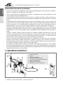
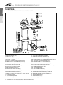
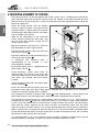
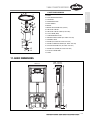
English MANUAL DE INSTRUCCIONES Y MANTENIMIENTO 1 ES Español 1. INSTRUCCIONES DE SEGURIDAD. Para reducir el riesgo de electrocución, no abrir las tapas superiores. No manipular el interior del triturador sanitario, recurrir siempre a personal cualificado. Para evitar posibles incendios o electrocución, no exponer este aparato a la lluvia o inundación. INDICE 1. 2. 3. 4 5. 6. 7. 8. 9. 10. 11. 12. 13. 14. INSTRUCCIONES DE SEGURIDAD. . . . . . . . . . . . . . . . . .01 COMPONENTES PRINCIPALES. . . . . . . . . . . . . . . . . . . . . . .02 INTRODUCCIÓN. . . . . . . . . . . . . . . . . . . . . . . . . . . . . . . . . . . . . . . . . . . . .03 DESCRIPCIÓN GENERAL. . . . . . . . . . . . . . . . . . . . . . . . . . . . . . . .03 4.1. Funcionamiento. MONTAJE DEL SISTEMA. . . . . . . . . . . . . . . . . . . . . . . . . . . . . . .04 5.1. Recomendaciones de instalación. 5.2. Conexión del suministro eléctrico. 5.3. Puesta en marcha. INDICACIONES PARA EL USUARIO FINAL. . . . . .06 OPERACIONES DE MANTENIMIENTO. . . . . . . . . . . . .07 7.1. Limpieza. 7.2. Guía de solución de problemas. 7.3. Desmontaje y extracción del motor. 7.4. Sustitución / limpieza válvula anti-retorno. ESPECIFICACIONES TÉCNICAS. . . . . . . . . . . . . . . . . . . . . .12 ESQUEMA DE MONTAJE Y SISTEMA DE VENTILACIÓN SECUNDARIA. . . . . . . . . . . . . . . . . . . . . . . . . .13 DESPIECES. . . . . . . . . . . . . . . . . . . . . . . . . . . . . . . . . . . . . . . . . . . . . . . . . . . .13 10.1. Conjunto cisterna empotada. 10.2. Conjunto triturador. 10.3. Conjunto caset. COTAS BÁSICAS. . . . . . . . . . . . . . . . . . . . . . . . . . . . . . . . . . . . . . . . . . . .15 INSTALACIÓN / MANTENIMIENTO . . . . . . . . . .16 / 18 DECLARACIÓN DE CONFORMIDAD CE. . . . . . . . . . .38 CONDICIONES GENERALES DE GARANTIA. . . .39 Español TRITURADOR SANITARIO MODELO T-604 CC INSTRUCCIONES DETALLADAS DE SEGURIDAD. Este aparato pueden utilizarlo niños con edad de 8 años y superior y personas con capacidades físicas, sensoriales o mentales reducidas o falta de experiencia y conocimiento, si se les ha dado la supervisión o formación apropiadas respecto al uso del aparato de una manera segura y comprenden los peligros que implica. Los niños no deben jugar con el aparato. La limpieza y el mantenimiento a realizar por el usuario no deben realizarlos los niños sin supervisión. Si el cable de alimentación está dañado, debe ser sustituido por el fabricante, por su servicio posventa o por personal cualificado similar con el fin de evitar un peligro. instrucciones disponibles en www.jimten.com TRITURADOR SANITARIO MODELO T-604 CC Español INSTRUCCIONES DETALLADAS DE SEGURIDAD. Todas las instrucciones de seguridad y de funcionamiento deben leerse antes de poner en marcha el aparato y guardadas para posibles consultas futuras. English Todas las indicaciones de seguridad, instrucciones y operaciones del usuario indicadas en este manual deben respetarse obligatoriamente. El aparato debe instalarse en forma y posición que no se impida la entrada y salida de aire por su parte lateral y superior. Debe de facilitarse el flujo de aire alrededor de la unidad cuando se instala en muros. La unidad debe estar situada lejos de fuentes de calor como: radiadores, estufas, u otros aparatos que generen calor. Este aparato se debe conectar al tipo de fuente de alimentación eléctrica indicada en estas instrucciones o en la etiqueta adhesiva colocada en el mismo. Esta unidad debe conectarse imperativamente a una base con toma de tierra debiéndose verificar que dicha toma es efectiva. El cable de alimentación debe colocarse de forma que no se pueda pisar, perforar, o ser dañado por cualquier tipo de objeto situado cerca del mismo. La limpieza debe efectuarse siempre con un paño humedecido con una solución de jabón neutro. No debiéndose utilizar limpiadores con disolventes o ácidos. Cuando se prevean periodos largos de tiempo sin utilización, deberá desconectarse la toma de corriente o el circuito eléctrico al que esté conectado, y poner especial atención en cerrar la llave de paso de alimentación de agua a la cisterna del inodoro y efectuar su descarga, así como las de cualquier aparato sanitario conectado a éste antes de desconectar el triturador. Evitar la entrada de todo tipo de objetos extraños no admitidos por la unidad como son: compresas, tampones, preservativos, algodón, bastoncillos, estropajos, esponjas, pelos, desechos de comida, bolsas de plástico, pañales, toallas de papel, etc. Colocar la etiqueta adhesiva que se suministra ensitio visible (por ejemplo visible en la tapa levantada del inodoro) Ante daños que requieran servicio técnico, como daños en el cable de alimentación, claros cambios en el funcionamiento habitual o que la unidad parezca no funcionar adecuadamente, las operaciones de mantenimiento deberán llevarse a cabo por personal especializado salvo cuando expresamente se indique lo contrario en estas instrucciones. 2. COMPONENTES PRINCIPALES. 1.- Cuerpo depósito. 2.- Tapas. 3.- Salida de impulsión. 4.- Entradas auxiliares Ø40-32. 5.- Conexión para manguito inodoro recto. 6.- Cable de alimentación. 7.- Filtro de carbón activo. 8.- Bastidor de cisterna empotrada, 3 2 4 7 6 4 8 1 5 4 2 - MANUAL DE INSTRUCCIONES Y MANTENIMIENTO TRITURADOR SANITARIO MODELO T-604 CC Con el triturador sanitario CICLON CC se resuelve el problema de la rehabilitación y creación de cuartos de baño completos en zonas como: buhardillas, sótanos, garaje, huecos de escalera, oficinas, fábricas, restaurantes, pubs, gimnasios, comercios, etc, e incluso por su bajo nivel sonoro, de un cuarto de baño dentro de un dormitorio. El triturador CICLON CC ha sido diseñado para eliminar de aguas negras, defecaciones y papel higiénico. No se debe instalar como triturador de cocina conectando fregaderos o aparatos equipados con bomba tales como lavadoras o lavavajillas, u otros equipos similares. Su atractivo y práctico diseño se ha realizado para que se integre perfectamente dentro del cuarto de baño, facilitando su instalación empotrada y así como en caso necesario, el desmontaje de sus componentes eléctricos para su mantenimiento, dado que en caso de avería, la independencia del conjunto motor del resto de la unidad (Caset), permite una rápida y limpia intervención en la unidad, evitando la situación de "fuera de servicio" mientras se repara. 4. DESCRIPCIÓN GENERAL. El triturador sanitario CICLON CC, permite la instalación y desagüe de tres aparatos sanitarios localizados en un mismo nivel (lavabo, bidet o ducha) y un inodoro. El inodoro (suspendido, salida horizontal) se conecta al triturador mediante el manguito recto (suministrado), y al bastidor / cisterna mediante los tornillos de anclaje facilitados. El producto se compone de 2 módulos independientes: - El cuerpo triturador, formado por un depósito, que recibe las conexiones de evacuación de los aparatos sanitarios y un conjunto caset-motor, extraíble, que contiene todos los mecanismos: el presostato, el motor, las cuchillas y la bomba. - El módulo cisterna empotrada, formado por un bastidor de acero galvanizado, al que se fija un tanque/depósito con los mecanismos de descarga y grifo flotador de llenado, un soporte sobre el que se fija el cuerpo del triturador, y todos los útiles de anclaje del inodoro (no suministrado). No incluye la placa de mando ni las placas embellecedoras(*), dispone de una amplia gama a seleccionar para adaptarse al diseño de su cuarto de baño. (*) según versiones. 4.1. Funcionamiento. Una vez instalado, el triturador se activa automáticamente al accionar la descarga de la cisterna empotrada, a través del inodoro o por el aporte de agua a través de la conexión auxiliar procedente de cualquiera de los aparatos sanitarios conectado al mismo. El agua y las materias residuales entran en la unidad elevando el nivel de agua, disparando el microinterruptor del presostato que activa el motor y la bomba. Las cuchillas trituran los sólidos que se reciben de la conexión al inodoro (o tomas laterales) girando a 2700 r.p.m. siendo triturados e impulsados por la bomba a través de la salida de evacuación hasta una tubería sanitaria o bajante. Dependiendo de la altura del tubo de descarga vertical, un ciclo de funcionamiento durará aproximadamente entre 7 y 12 segundos. En caso de una puesta en marcha durante un tiempo excesivo, o de continuos arranques del triturador, se deberán comprobar la ausencia de fugas de la cisterna empotrada al inodoro y los aparatos sanitarios conectados al triturador en las tomas laterales. MANUAL DE INSTRUCCIONES Y MANTENIMIENTO - 3 English El triturador sanitario CICLON CC ha sido ideado para permitir la instalación y desagüe de instalaciones fijas de inodoro suspendido o cuartos de baño (WC, lavabo, bidet o ducha) en ubicaciones no habituales, a distancia y/o distinto nivel de una bajante, siempre y cuando se disponga de una bajante a una distancia horizontal máxima de 62 m o vertical de 6 m, o una combinación de ambas según se describe en este manual. Español 3. INTRODUCCIÓN. TRITURADOR SANITARIO MODELO T-604 CC English Español 5. MONTAJE DEL SISTEMA. - Colocar CICLON CC en el bastidor, y el conjunto en el lugar deseado. Conecte las entradas y salida. (ver esquema de conexión en página 10). Prever una distancia mínima desde del tubo de la bajante al triturador de un metro, de forma que éste funcione el tiempo adecuado para eliminar los desechos con eficacia. - Presentar el módulo bastidor sobre el forjado, regule la altura de los pies de soporte del bastidor para dejar la base del cuerpo del triturador enrasado con la línea del suelo terminado, marque los puntos de fijación del bastidor a la pared posterior o a la estructura de pared ligera. 훿 훽 -Verifique que los componentes internos de la cisterna, mecanismo de descarga, grifo flotador, etc, no se han desplazado durante el transporte. - Monte la llave de paso en el tanque (1/2”), seleccione el agujero según la alimentación sea superior o lateral. - Inserte la tapa de protección de obra en el orificio frontal seleccionado 훽. - Atornille el módulo bastidor al suelo y a la pared o estructura ligera 훾. - Prevea la conexión eléctrica antes de alicatar o cerrar la pared ligera. Recomendamos una base eléctrica normalizada IEC que facilite su desmontaje en caso de mantenimiento. - Realice la conexión de la alimentación a la toma roscada de 1/2” suministrada y verifique que no fuga 훿. - Instale las tapas de protección de obra tanto en la descarga del como en la alimentación a la cisterna de forma provisional hasta que finalice la obra y coloque el sanitario. - Rosque las varillas de sujeción del WC suspendido y protéjalas (fundas suministradas) . - Instale el acabado frontal de la cisterna (pared ligera, obra, alicatado) con el acabado seleccionado. Respete los huecos de registro indicados (440x310 mm registro inferior y huecos de regulación en profundidad para los imanes) para poder realizar el mantenimiento del triturador. Se suministra plantilla de corte. - Recorte el sobrante del manguito recto de alimentación de WC y la alimentación de WC. - Conecte el manguito y la alimentación al inodoro y encájelo con la cisterna empotrada. Verifique el correcto ajuste libre de fugas. - El triturador dispone de 2 conexiones laterales de 1 1/2” provistas de válvula anti-retorno , y una conexión superior de 1 1/2” equipada con válvula anti-retorno, que le permite conectarlo a aparatos sanitarios. En el caso que no se utilicen, el equipo se suministra con tapones para anularlas. La unidad recibe agua del aparato sanitario conectado por gravedad. El tramo hacia el triturador debe tener una caída positiva (1% - 2%) que permita el drenaje cuando el triturador está parado. 4 - MANUAL DE INSTRUCCIONES Y MANTENIMIENTO DISTANCIA VERTICAL English Español TRITURADOR SANITARIO MODELO T-604 CC DISTANCIA HORIZONTAL - Cuando se conecta un elemento sanitario a las tomas laterales inferiores, se debe tener en cuenta en su instalación una altura mínima de 180 mm entre la parte inferior del plato de ducha y la base del triturador para proporcionar el suficiente desnivel hacia las entradas de desagüe. - Se recomienda la utilización de desagües no sifónicos especialmente en la instalación del plato de ducha (ver recomendaciones de conexión en la página 13 para la instalación de un sistema de ventilación secundaria si esto último no fuera posible). - El triturador sanitario CICLON CC dispone en la impulsión de una conexión hembra Ø32 mm de PVC para encolar, o una conexión con manguito y abrazaderas que permite la adaptación a distintos diámetros de salida provista de una válvula antiretorno, se recomienda instalar una válvula de cierre en el tubo de impulsión vertical que impida el vaciado del mismo en caso de sustitución. - Conectar el tubo de desagüe con la bajante, el triturador bombea a través del tubo de evacuación (Ø32) mediante los adaptadores suministrados, hasta una altura máxima de 6 m o hasta una distancia horizontal máxima de 52 m, o una combinación de las dos (ver diagrama), se debe tener en cuenta siempre una pendiente mínima del 1% constante hasta el punto de descarga. Para obtener un resultado óptimo, Jimten recomienda el empleo de una tubería de Ø32 mm. - En instalaciones combinadas (vertical y horizontalmente) se debe tener en cuenta que 1 metro de elevación vertical equivale aproximadamente a 10 metros de recorrido horizontal. - Todas aquellas instalaciones que deban elevarse verticalmente deben realizar esta elevación directamente sobre el triturador. La instalación de curvas o cambios de sentido producen una pérdida de carga que se debe restar a las distancias máximas de bombeo (reducir aprox. 1 m de la distancia máxima de recorrido por cada curva). Las distancias de bombeo máximas se indican para un tubo de evacuación de 32 mm. El uso de tuberías de diámetro inferior pueden reducir las alturas de bombeo. MANUAL DE INSTRUCCIONES Y MANTENIMIENTO - 5 TRITURADOR SANITARIO MODELO T-604 CC English Español 5.1. RECOMENDACIONES DE INSTALACIÓN. TUBERÍA – Utlizar tubería de PVC Ø32 mm a encolar para la impulsión para descarga. Evitar tramos curvos (sifones) que puedan retener ciertos sólidos y producir obstrucciones. TUBERÍA – Utilizar tubería de PVC Ø32 mm a encolar para la impulsión para descarga. Evitar tramos curvos (sifones) que puedan retener ciertos sólidos y producir obstrucciones. También se pueden emplear otras tuberías (28-22mm) con adaptador de junta y abrazadera metálica. SOPORTES DE TUBOS – Los tubos de evacuación deben sujetarse con los accesorios adecuados de acuerdo con las indicaciones del fabricante. CURVAS – No utilizar codos a 90°, emplear curvas en su lugar. Si no se dispone de curvas se pueden emplear dos codos a 45° en su lugar. EVITAR TRAMOS EN DIAGONAL – Los tramos de la instalación deben ser siempre verticales u horizontales, nunca deben instalarse tramos diagonales. PROTECCIÓN CONTRA HELADAS – En zonas con riesgo de heladas por bajas temperaturas, todos los tramos de tubería que tengan riesgo de congelarse deben protegerse con aislantes térmicos. CONEXIÓN CON LA BAJANTE – Realizar la conexión con la bajante mediante derivación a 45°. En caso que la unión con la bajante quede por debajo de la base del triturador, se debe conectar una válvula de ventilación (tipo Jimten A-69) en el punto más alto de la instalación para evitar el vaciado del triturador. DESCARGA – El tramo de descarga siempre debe conectarse a la red de evacuación, no debe evacuar nunca en desagües abiertos, sumideros, etc. VENTILACIÓN – El triturador debe instalarse en su posición prevista sobre el bastidor. Se recomienda su instalación en paredes ligeras. Y el empleo del embellecedor frontal (opcional) de dos piezas, que permita una correcta ventilación del mismo. APARATOS SANITARIOS – El triturador está preparado para la conexión de un inodoro y 3 aparatos sanitarios (lavabo, bidet o ducha) , no permite la conexión de electrodomésticos como lavadoras o lavavajillas equipados con equipo de bombeo que puede interferir el correcto funcionamiento del triturador. 5.2. CONEXIÓN DEL SUMINISTRO ELÉCTRICO. Conectar todos los elementos sanitarios y red de evacuación antes de realizar la conexión eléctrica. Cuando se instale un cuarto de baño, separar al menos un metro el triturador de cualquier bañera o ducha. Es necesario una toma eléctrica 220 V, base europea 10-16 A con dos polos y toma a tierra de uso exclusivo para la conexión del triturador. Se recomienda situar una clavija eléctrica de forma accesible tras el hueco de registro previsto del triturador y que no interfiera con el desmontaje del caset en caso que fuera necesario. El triturador se debe conectar a una red protegida por interruptor diferencial. 6 - MANUAL DE INSTRUCCIONES Y MANTENIMIENTO TRITURADOR SANITARIO MODELO T-604 CC 6. INDICACIONES PARA EL USUARIO FINAL. El triturador una vez instalado y conectado a la red eléctrica no necesita un mantenimiento especial en condiciones normales de utilización. Cada vez que se acciona el inodoro o el de un aparato sanitario conectado al mismo, el aporte de agua procedente de éste, produce que el triturador entre automáticamente en funcionamiento y pare cuando termine de bombear sin intervención del usuario. Para el buen funcionamiento del triturador, descargar únicamente en el mismo aguas residuales, defecaciones y papel higiénico.. Notas preventivas. - No arrojar elementos sólidos extraños tales como: compresas, tampones, preservativos, algodón, bastoncillos, estropajos, esponjas, pelos, desagües de fregaderos, deshechos de comida, bolsas de plásticos, pañales, toallas de papel, cigarrillos encendidos, otros materiales que ardan, etc, ya que pueden dañar o bloquear el triturador. - No verter líquidos corrosivos como: ácidos, disolventes, aceites, pinturas, decapantes, ya que pueden deformar y afectar el buen funcionamiento del triturador. - En estos casos, los daños no están cubiertos por la garantía. - No introducir en el interior de la cisterna del inodoro sistemas de dosificación de desinfectante o limpiador de inodoro, ya que pueden deteriorar los materiales de los mecanismos de descarga y llenado de la cisterna, produciendo fugas, y haciendo arrancar sucesivamente el sistema. - Recomendamos colocar la etiqueta adhesiva suministrada con esta documentación, en un lugar visible como el interior de la tapa del inodoro, como indicativo de atención ante el vertido de residuos extraños. - No utilizar el inodoro ni ninguno de los aparatos sanitarios conectados al triturador cuando se produzca un corte eléctrico. - Cuando se prevea una ausencia prolongada, o se trate de instalaciones de uso aislado, recomendamos cerrar la llave de paso de alimentación a la cisterna y descargarla a continuación dejándola vacía, evitando riesgo de fugas. - En zonas con riesgo de heladas, se recomienda proteger las tuberías con aislantes térmicos, así como la preparación de todo el sistema (cisterna, triturador y tubos de evacuación) mediante: - El cierre de la llave de paso de alimentación a la cisterna y su descarga. - El llenado de la cisterna con líquido anticongelante especial para fontanería. - Volver a descargar la cisterna. El líquido anticongelante recorrerá la instalación y llenará el tubo de evacuación. - La garantía no cubre daños producidos en el triturador por la congelación 7. OPERACIONES DE MANTENIMIENTO. El triturador sanitario Jimten ha sido diseñado para proporcionarle una alta fiabilidad y años de funcionamiento, a continuación se detallan las operaciones de mantenimiento más comunes, y una guía rápida solución de problemas usted mismo puede resolver fácilmente. MANUAL DE INSTRUCCIONES Y MANTENIMIENTO - 7 English Para la puesta en marcha de la unidad: - Verificar que el inodoro esté limpio de sólidos extraños. - Abrir la llave de paso de llenado de la cisterna y regular la descarga para un mínimo de 6 litros necesarios para el correcto trabajo de la unidad. - Comprobar la conexión de la toma eléctrica. - Accionar la descarga de la cisterna varias veces, depositando entre una y otra varias hojas de papel higiénico para comprobar el correcto funcionamiento de la evacuación. Después de cada descarga no deben quedar residuos en la taza del inodoro. Español 5.3. PUESTA EN MARCHA. TRITURADOR SANITARIO MODELO T-604 CC English Español 7.1. LIMPIEZA. Para Para la limpieza del inodoro conectado al triturador, se recomienda la utilización de cualquier limpiador del mercado de calidad reconocida, de base no ácida. En zonas con alto grado de dureza de agua y con el fin de eliminar los depósitos de cal, se recomienda realizar periódicamente una limpieza siguiendo los siguientes pasos: - Desconectar el triturador de la red eléctrica. - Verter en el inodoro una mezcla de 1 litro de vinagre y 3 de agua (aproximadamente) - Dejar actuar durante unas horas. - Volver a conectar el triturador y poner en marcha. 7.2. GUÍA DE SOLUCIÓN DE PROBLEMAS. Antes de realizar ninguna acción, verifique los puntos siguientes: - Compruebe que los mecanismos de llenado y descarga del inodoro están en buenas condiciones y libres de fugas. - Compruebe que el triturador está conectado en su base de enchufe, y éste tiene corriente. (compruebe que el interruptor diferencial no haya saltado y el magnetotérmico esté conectado) - Compruebe que la protección térmica del triturador no haya actuado. (el triturador incorpora un sistema de desconexión automática por exceso de temperatura), esperando aproximadamente unos 20 minutos (puede variar dependiendo de las condiciones de temperatura ambiente) la unidad se reactivará automáticamente.En caso de puesta en marcha durante un tiempo excesivo, o de continuos arranques del triturador, se deberán comprobar la ausencia de fugas en el inodoro y en el resto de los aparatos conectados. En caso que haya retorno de agua al triturador a través de la válvula antiretorno del tubo de evacuación, comprobar que ésta cierre correctamente (verificar que la clapeta asienta correctamente) y sustitúyala o límpiela en caso necesario (ver página 12) PROBLEMA CAUSA SOLUCIÓN - El triturador no arranca. - Está desconectado. - La toma eléctrica no es correcta. - Se ha activado la protección eléctrica. - Conectar correctamente el aparato. - Comprobar la conexión eléctrica. - Esperar 20 min. Aprox. hasta que se enfríe el motor. - Salta el interruptor diferencial - Toma de tierra del motor defectuosa. - Motor fuera de servicio. Contacte con el S.A.T - El motor funciona pero no descarga o lo hace lentamente. - Obturación en el tubo de evacuación. - Limpiar el tubo de evacuación. - El motor zumba pero no gira. - Turbina o cuchillas bloqueadas por cuerpo extraño. - Ver operaciones de mantenimiento (desmontaje y extracción del motor, página 11) - Después de evacuar, el motor arranca y para indefinidamente. - Fuga de la válvula antiretorno, pérdida de agua de la cisterna o de las conexiones auxiliares. - Limpiar válvula antiretorno del tubo de impulsión. - Revisar y sustituir juntas del descargador de la cisterna o de los grifos de los aparatos sanitarios conectados. - El motor no se para. - Exceso de altura o longitud del tubo de - Replantear la instalación de evacuación. evacuación para el diámetro de tubo - Realizar el proceso de desincrustación empleado. (limpieza 7.1) - Pérdida de potencia por exceso de - Contacte con el S.A.T. codos en la instalación. - Obstrucción de los tubos de evacuación por acumulación de cal. - Mal funcionamiento del micro-interruptor. 8 - MANUAL DE INSTRUCCIONES Y MANTENIMIENTO CAUSA SOLUCIÓN - El motor funciona con la descarga del WC pero no con el agua del otro aparato sanitario conectado. - Las conexión auxiliar está obstruida o la válvula antiretorno bloqueada. - Falta de aireación o pendiente en la conexión auxiliar. - Mal funcionamiento del micro-interruptor. - Limpiar el tramo de tubería de la conexión auxiliar. - Dotar a la instalación de ventilación secundaria, o instale válvula de aireación (tipo Jimten A-69). / Replantear la instalación. - Contacte con el S.A.T. - Después de evacuar, el motor arranca sucesivas veces antes de parar definitivamente. - Retorna el agua al triturador. La válvula - Realizar varias descargas con agua antiretorno no funciona adecuadamente. limpia y limpiar la válvula antiretorno. - Acumulación de residuos en el interior del inodoro. - Suministro de agua inadecuado de la cisterna. - Ajuste el nivel de agua de la cisterna (6 litros mínimo). - Retorno de agua al plato de ducha. - No se ha contemplado la pendiente mínima necesaria en la instalación de evacuación. (ver altura plato ducha). - Mal funcionamiento de las válvulas antiretorno de la conexión auxiliar. - Replantear la instalación (elevando la altura del plato de ducha). - Limpieza y/o sustitución de la válvula antiretorno de la conexión lateral. - Ruido extraño al funcionar el motor. - Obstrucción / Atasco por caída de cuerpo extraño en el inodoro. - Extraer el objeto del interior del triturador. (ver desmontaje y extracción del motor 7.3.). - Aparición de olores procedentes del triturador. - Desgaste del filtro de carbón activo. - Sustitución del filtro (Contacte con el S.A.T.) - No desagua bien el plato de ducha. - Posible obstruccióndel desagüe - Desagüe plato ducha sifónico, genera pistón de aire en la evacuación. - Altura insuficiente del plato de ducha. - Limpieza tubería evacuación. - Eliminar el sifón de la válvula plato de ducha. - Replantear la instalación (elevando la altura de plato de ducha). - Fuga de agua por la pared. - Posible conexión defectuosa del manguito de inodoro o de la alimentación de la cisterna. - Rotura del inodoro. - Verifique la estanqueidad entre la unión del manguito de inodoro o de la alimentación del inodoro y el sanitario. - Sustituya el inodoro. Compruebe que se ha instalado correctamente el inodoro sobre los tornillos soportes con las juntas suministradas. - No funciona la descarga tras pulsar la placa de mando - Cables de accionamiento rotos o monta- - Retire la placa de mando, compruebe la dos de forma incorrecta. unión del cable de descarga simple y - Rotura en la placa de mando. descarga completa está bien instalada. - Descargador en cisterna empotrada - Reemplace la placa de mando. defectuoso. - Reemplace el descargador de la cisterna empotrada. - Perdida de agua en la cisterna - Acumulación de suciedad en el cierre del mecanismo. - Grifo flotador defectuoso. - Llave de paso o latiguillo con fugas. Mecanismo de descarga o base defectuosa. - Retire la placa de mando, extraiga el mecanismo, limpie la junta y la base del descargador, de los sedimentos que puedan haberse acumulado. - Retire la placa de mando y remplace el grifo flotador. - Reemplace el componente afectado. - Reemplace el mecanismo de descarga o su base. MANUAL DE INSTRUCCIONES Y MANTENIMIENTO - 9 English PROBLEMA Español TRITURADOR SANITARIO MODELO T-604 CC TRITURADOR SANITARIO MODELO T-604 CC English Español 7.3. DESMONTAJE Y EXTRACCIÓN DEL CONJUNTO CASET. Antes de realizar cualquier reparación, muy importante verificar que ha desconectado el cable de corriente de su base o si no fuera accesible, ha desconectado el circuito eléctrico al que esté conectada la unidad. Para el caso que haya adquirido junto al equipo la placa embellecedora: - Extraiga la placa de mando, para ello en el caso de ser 훾 de instalación en superficie, empuje hacia un lado el conjunto y tire de ella por un lateral hacia usted 훽. Si se trata de instalaciones enrasadas, pulse ambos pulsadores y tire del cristal hacia fuera 훽. Retire los tornillos del marco de sujeción, esto liberará la placa embellecedora superior - La placa embellecedora está fijada sobre un riel inferior, 훽 y sujeta mediante imanes en la parte superior 훾. Tire hacia el frontal y hacia el arriba para desencajar la placa de su alojamiento inferior. Para el caso que haya realizado otro tipo de instalación: - Retire el registro que haya previsto, para acceder al compartimento bajo el tanque de la cisterna. En todos los casos: - Para retirar el conjunto caset (motor, presostato, cuchillas, bomba, condensador) retire los 7 tornillos de anclaje al cuerpo principal 훿. - Retire los tornillos del caset a la izquierda de su unidad. Los tornillos quedan sujetos tras llegar al final del recorrido útil. ¡Importante! Antes de retirar los tornillos de caset asegurese que el nivel del inodoro es bajo. En caso contrario vacielo, existe el riesgo de verter agua en la instalación empotrada si no lo hace y afloja los tornillos de caset. - Retire la carcasa / protección del ventilador. - Retirar la junta retenedora del cable al conjunto caset, presionando desde los extremos y liberando el tope, desconecte las conexiones (faston) del cable eléctrico al motor y presostato. Prevea un lugar accesible donde colocar el cable (tramo empotrado) hasta su re훿 conexión. - Extraer manualmente todo el conjunto caset tirando del motor hacia arriba . Nota de seguridad: - Prestar atención al motor, que tras un periodo de uso puede estar caliente, atención a las cuchillas del triturador que están muy afiladas. - Sustituir el conjunto caset por el de repuesto y volver a montar siguiendo los pasos en sentido contrario. (ver conexiones eléctricas pagina 11), atornille y coloque la cubierta del caset. Todo el proceso se realiza en únicamente 15 minutos 10 - MANUAL DE INSTRUCCIONES Y MANTENIMIENTO (motor – presostato – TRIAC – cable) A Cable de red 훽 – Compuesto de fase (marron), neutro (azul) y tierra (amarillo/verde) H I B Cable Triac 훾 – fase (marron) a posición 3 del presostato conexión faston hembra. C Cable de red 훿 – fase (marron) al triac . D Cable de triac – fase (marron) al motor. E Cable de triac – fase (marron) a posición 1 del presostato y al motor. F G Neutro (azul) y tierra (amarillo/verde) conexión faston hembra. Si el cable de red está dañado, debe de sustituirse por el fabricante, su servicio técnico autorizado o por un técnico cualificado para prevenir cualquier daño. 7.4. SUSTITUCIÓN / LIMPIEZA VÁLVULA ANTIRETORNO DE IMPULSIÓN. 훾 Antes de comenzar la sustitución / limpieza, realizar varios ciclos de descarga de la cisterna y (si ha sido instalada) cerrar la válvula de paso del tubo de evacuación vertical y desconectar la unidad de la corriente eléctrica eléctrica o desconecte el circuito eléctrico donde esté conectado. - Extraiga el registro previstro para acceder a la udidad. - Retire la tuerca de 1 1/4” 훾. - Suelte las bridas de anclaje del tubo de impulsión para poder desplazar el tubo y facilitar así el desmontaje. - Prever un recipiente para la recogida del agua, vaciar el tubo de impulsión en carga, accionando la clapeta de la válvula antiretorno. 훿 - Retirar la tuerca clip 훿. - Revisar o sustituir el conjunto portajunta más junta antiretorno . - Seguir los pasos en sentido inverso para el montaje de la válvula. Realizar varios ciclos de descarga de la cisterna antes de volver a poner en servicio el triturador con el fin de eliminar el aire de la instalación de impulsión. MANUAL DE INSTRUCCIONES Y MANTENIMIENTO - 11 English ESQUEMA DE CONEXIONES ELÉCTRICAS. Español TRITURADOR SANITARIO MODELO T-604 CC TRITURADOR SANITARIO MODELO T-604 CC English Español 8. ESPECIFICACIONES TÉCNICAS. Entradas: Inodoro: Auxiliar: Manguito WC DE Ø90 mm. 2 Tomas lateral de 1 1/2 x 40 mm para tubos lisos de Ø40 mm. 1 Toma superior de 1 1/2 x 40 mm para tubos lisos de Ø40 mm Salida: Impulsión: Válvula de retención: Ø32 mm para tubo liso. (Ø22 y Ø28 mediante adaptador). 1 1/4” x 32 mm desmontable. Bomba: Voltaje: Fusible: Potencia consumida: Condensador: Conexión Eléctrica: Altura máxima impulsión: Distancia horiz.máx.de impulsión: ~ 240 V, AC, 50 Hz. Térmico. 0.47 kW. 14 µF / 450 V. Para base normalizada IEC 6m 52 m Dimensiones y peso: Dimensiones: Peso: Peso incluido embalaje: Triturador: 470 x 146,5 x 315 mm 6.8 Kg 8.2 Kg Cisterna empotrada: Bastidor: Cisterna empotrada: 500 x 1.1125 x 150 mm 16.3 Kg 17.6 Kg Autoportante, con protección superficial por pintura epoxy, acero galvanizado. 4 puntos de anclaje. Premontado. Incluye elementos de anclaje. Rango ajuste entresuelo terminado y estructura 200 mm. Regulable entre profundidad 155-205 mm. Tornillos de fijación del WC de M12. Adaptable inodoros de anclajes a 180 mm de separación. Tanque: Para pulsador de hueco de registro pequeño. Pulsador frontal. Con aislamiento de protección anti-condensacion. Descarga doble regulable (9/4.5 litros – 6/3 litros). Accionamiento de pulsador por cable de acero, conexión por enchufe rápido. Componentes: Tapones de protección de obra. Llave de escuadra de 1/2”. Manguito de inodoro d.90. 180 mm de longitud. Grifo flotador y flexible de apriete manual. Pueden desmontarse para mantenimiento. Clase I. Mecanismo de descarga de cierre amortiguado. NOTA: Los datos facilitados en este manual de instrucciones y mantenimiento, como consecuencia de la constante mejora y evolución de nuestros productos, pueden variar sin previo aviso. Éste manual de instrucciones y mantenimiento no tiene carácter contractual y toda la información se da de buena fé. 12 - MANUAL DE INSTRUCCIONES Y MANTENIMIENTO TRITURADOR SANITARIO MODELO T-604 CC Español 9. ESQUEMA DE MONTAJE Y SISTEMA DE VENTILACIÓN SECUNDARIA. English CICLON CC, WC Y LAVABO. A – CONEXIÓN A TUBERÍA DE VENTILACIÓN EXISTENTE. C – TUBERÍA ENTRADA DESAGÜE 1% PENDIENTE. B – TUBERÍA DE IMPULSIÓN Ø32 CON 1% DE PENDIENTE. 10. DESPIECE. CONJUNTO CISTERNA EMPOTRADA. 1. - GRIFO FLOTADOR 2. - VÁLVULA DE CORTE 3. - BLOQUEO DESCARGADOR 3 4. - PROTECCION ALICATADO 5. - GRIFO FLOTADOR 4 2 6. - TORNILLOS FIJACION WC 7. - MANGUITOS INODORO 8. - SOPORTE MANGUTO DESCARGA 9. - SOPORTE TRITURADOR 5 2 3 4 1 4, 5 6 7, 7 5 8 DN 50 6 9 2 x 6 x MANUAL DE INSTRUCCIONES Y MANTENIMIENTO - 13 TRITURADOR SANITARIO MODELO T-604 CC Español 10. DESPIECE. CONJUNTO TRITURADOR Y CONJUNTO CASET. 24 English 30 12 9A 9B 19 11 10 13 8A 14A 8B 14B 31 20B 20A 6A 7B 6B 7A 20C 2 20D 20E 20F 1 15 16 28 3 4 5 6B 6A 32 33 22A 22B 17 29 3 30 24 22C 21 1. CUERPO DEPSITO (PP COPO) 2. TRAVESAO CUERPO (ABS) 3. TUERCA 1 1/2" (PP) 4. TAPN OBTURADOR 1 1/2" (PVC) 5. JUNTA AZUL 1 1/2" (EVA) 6A. JUNTA VLV. ANTIRETORNO (CAUCHO NITRILO) 6B. PORTAJUNTA VLV. ANTIRETORNO (PP+TALCO) 7A. BOYA AIREACIN (PP) 7B. JUNTA BOYA AIREACIN (CAUCHO) 8A. TAPA ESTANCA DEPSITO (PP+TALCO) 8B. JUNTA TAPA ESTANCA (CAUCHO) 9A. DEPSITO CARBN ACTIVO (PP) 9B. TAPA DEPSITO CARBN ACTIVO (PP) 10. TAPA EMBELLECEDOR DEPSITO (PP) 11. TAPA EMBELLECEDOR CASETE (PP) 12. TAPA EMBELLECEDOR CIRCULAR (PP) 13. TORNILLO SUJECIN TAPA CIRCULAR (AC. INOX. AISI-304) 14A. CASETE (PP COPO) 14B. JUNTA CASETE (CAUCHO) 15. TUERCA 1 1/4" (PP) 16. TUBO PVCb 17. JUNTA TRICA CODO IMPULSIN (NBR) 19. TORNILLO SUJECIN (AC. INOX. AISI-304) 20A. TUERCA CLIP VLV. ANTIRETORNO (PP) 20B. PARTE SUPERIOR VLV. ANTIRETORNO (PVC PROT. SOLAR) 20C. JUNTA TRICA VLV. ANTIRETORNO (NBR) 20D. PARTE INFERIOR VLV. ANTIRETORNO (PP) 20E. JUNTA PLANA VLV. ANTIRETORNO (NITRILO) 20F. ENLACE TUERCA LOCA/ENCOLAR (PVC) 21. TOPES INFERIOR CUERPO (CAUCHO SANTOPRENE) 22A. MANGUITO CONEXIN WC (EVA) 22B. JUNTA MANGUITO WC 22C. ANILLO MANGUITO WC (PP) 24. BRIDA METLICA 32-50 (AC. INOX. W2) 28. CILINDRO REFUERZO MANGUITO FLEXIBLE (PP) 29. ARANDELA MANGUITO FLEXIBLE (PP) 30. MANGUITO FLEXIBLE (CAUCHO TERMOPLST.) 31. CENTRADOR BOYA (PP) 32. CODO IMPULSIN (PVC) 33. TUERCA 1" (PP) 14 - MANUAL DE INSTRUCCIONES Y MANTENIMIENTO TRITURADOR SANITARIO MODELO T-604 CC 4 1. CASETE (PP COPO) 2. JUNTA ESTANQUEIDAD CASETE (CAUCHO NEGRO) 3. CONDENSADOR (CON JUNTA PVC FLEX.) 4. MANGUERA TRES HILOS 8 6 9 5. JUNTA PASAMUROS (CAUCHO) 19 6. MOTOR 7 Español DESPIECE CONJUNTO CASET. 18 3 7. DISCO AISLANTE MOTOR (PA+FV) 2 8. PRESOSTATO 1 9. JUNTA PRESOSTATO (PVC FLEX) 10. JUNTA TRICA 22x3 (NBR) 11. TAPONES TORNILLO MOTOR (CAUCHO SANTOPRENE) 12. TORNILLOS SUJECIN MOTOR (AC. INOX. AISI-304) 10 13. CIERRE CERMICO 12 14. ROTOR+CUCHILLAS (PP COPO+AC. INOX. AISI-301) 13 11 15. TORNILLO SUJECIN ROTOR (AC. INOX. AISI-304) 14 16. TAPA ROTOR CASETE (AC. INOX. AISI-301) 15 16 17. TORNILLOS TAPA ROTOR (AC. INOX. AISI-304) 17 18. PASAMUROS CABLE 19. TRIAC 11. COTAS BÁSICAS. MêN. 150 mm MçX. 220 mm 1.125 mm 1/2ÕÕ MêN. 75 mm 500 mm MANUAL DE INSTRUCCIONES Y MANTENIMIENTO - 15 English 5 TRITURADOR SANITARIO MODELO T-604 CC English Español 12. INSTALACIÓN. 16 - MANUAL DE INSTRUCCIONES Y MANTENIMIENTO English Español TRITURADOR SANITARIO MODELO T-604 CC MANUAL DE INSTRUCCIONES Y MANTENIMIENTO - 17 TRITURADOR SANITARIO MODELO T-604 CC English Español 12. MANTENIMIENTO. 18 - MANUAL DE INSTRUCCIONES Y MANTENIMIENTO English INSTALLATION AND MAINTENANCE MANUAL. 1 EN English 1. SAFETY INSTRUCTIONS. To reduce risk of electrocution, do not open top covers. Do not manipulate the internal components of the sanitary macerator. Always have a qualified technician to service your unit. INDEX 1. 2. 3. 4 5. 6. 7. 8. 9. 10. 11. 12. 13. 14. SAFETY INSTRUCTIONS. . . . . . . . . . . . . . . . . . . . . . . . . . . . . . . .19 MAIN COMPONENTS. . . . . . . . . . . . . . . . . . . . . . . . . . . . . . . . . . . . .20 INTRODUCTION. . . . . . . . . . . . . . . . . . . . . . . . . . . . . . . . . . . . . . . . . . . . .21 GENERAL DESCRIPTION. . . . . . . . . . . . . . . . . . . . . . . . . . . . . . . .21 4.1. Operation. SYSTEM ASSEMBLY. . . . . . . . . . . . . . . . . . . . . . . . . . . . . . . . . . . . . .22 5.1. Installation recommendations. 5.2. Electrical supply connection. 5.3. System start. INDICATIONS FOR FINAL USER. . . . . . . . . . . . . . . . . . . . .25 MAINTENANCE OPERATIONS. . . . . . . . . . . . . . . . . . . . . . . .25 7.1. Cleaning. 7.2. Problem solution guide. 7.3. Disassembly and removal of the motor. 7.4. Substitution and cleaning non-return valve. TECHNICAL SPECIFICATIONS. . . . . . . . . . . . . . . . . . . . . . . .30 INSTALLATION SCHEME AND SECONDARY VENTILATION SYSTEM. . . . . . . . . . . . . . . . . . . . . . . . . . . . . . . . . .31 SPARE PARTS. . . . . . . . . . . . . . . . . . . . . . . . . . . . . . . . . . . . . . . . . . . . . . .31 10.1. Cistern frame set. 10.2. Sanitary macerator set. 10.3. Caset Set. BASIC DIMENSIONS. . . . . . . . . . . . . . . . . . . . . . . . . . . . . . . . . . . . . .33 INSTALLATION / MAINTENANCE . . . . . . . . . . . .34 / 36 CE PERFORMANCE DECLARATION. . . . . . . . . . . . . . . .38 GENERAL WARRANTY CONDITIONS. . . . . . . . . . . . . . .39 Español SANITARY MACERATOR MODEL T-604 CC To prevent risk of fire or electrocution, do not expose the unit to rain or flooding. DETAILED SAFETY INSTRUCTIONS. This unit can be used by child over 8 years, and by people with reduced physical, sensorial or mental capacities, with lack of experience or knowledge, provided that they have been given proper supervision or training related to the usage of this unit in a safe manner and that they understand risks involved in its usage. Children should not play with the unit. Cleaning and maintenance to be carried out by the end user should not be done by children unattended. If the power supply cable is damaged, it must be substituted by the manufacturer, its aftersales service or qualified technicians to prevent risks. Instructions available at: www.jimten.com T-604 CC WASTE DISPOSER Español DETAILED SAFETY INSTRUCTIONS. All the safety and operation instructions must be read before switching on the unit and stored for future reference. English All safety, operation and instructions indication must be compulsory complied. The unit must be installed so the air coming in and out of it is not obstructed. Air should move freely when the unit is installed within walls. The unit should be installed far from heat sources such as: radiators, heaters, stoves, or other heat generating devices. This unit must be connected to the type of electrical source indicated in this instructions or the adhesive sticker attached. This unit must be imperatively connected to an earth grounded base, which effectiveness should be checked. The electrical supply cable should be placed in such a way it could not be stepped over, be perforated or damaged by any object near it. The waste disposer must be cleaned with a damp cloth moistened with a mild soap solution. Do not employ cleaning products with solvents or acids. When long non-use periods are expected, disconnect the plug from the socket. Take special care of turning off the stopcock allowing the water supply to the lavatory cistern and also in every sanitary appliance connected. Empty the cistern before switching off the waste disposer. Do not let in any sort of foreign objects that the unit does not accept such as: sanitary towels, tampon, condoms, cotton, cotton buds, scouring pads, sponges, hairs, food waste, plastic bags, nappies, paper towels, etc. Stick the adhesive label provided on a visible place near the appliance. Damages that require technical support such as: Damage in the power supply cable, appliance working inadequately or differently, must be repaired by qualified professionals. Except otherwise stated in this manual, all maintenance and repairing operations must be carried out by qualified staff, unless specifically stated in these instructions. 2. MAIN COMPONENTS. 1.- Body tank. 2.- Covers. 3.- Outlet. 4.- Auxiliary inlets Ø40-32. 5.- Connection for Pan Connector. 6.- Electrical supply. 7.- Active carbon filter. 8.- Concealed Cistern Frame. 3 2 4 7 6 4 8 1 5 4 20 - INSTRUCTIONS AND MAINTENANCE GUIDE T-604 CC WASTE DISPOSER The CICLON CC sanitary waste disposer solves the problem of creation and restoration of secondary bathrooms in places such as: attics, basements, garages, shafts and staircase, offices, factories, restaurants, pubs, gyms, shops, etc. and even though thanks to its low sound level a bathroom within a bedroom. Our CICLON CC waste disposer is designed to evacuate sewage, defecations and toilet paper. It must not be installed as food waste disposer connected to kitchen sinks or appliances equipped with pumps such as washing machines or dishwashers. Its attractive and practical design perfectly fits into the bathroom and makes easier the concealed installation and its dismantling in case of maintenance, as thanks to the independence of the motor set from the rest of the unit, it allows an easy access and a fast replacement thereof, thus avoiding the “out of service” situation while being repaired. 4. GENERAL DESCRIPTION. The CICLON CC sanitary waste disposer allows the simultaneous installation and drainage of three sanitary appliances , placed at a same level (washbasin, bidet or shower) and a lavatory. The wallhung lavatory (with a horizontal outlet) is connected to the waste disposer by means of a coupling (provided), and a frame/tank with the fixing screws (supplied). The waste disposer consists of two independent modules: - The sanitary macerator body, formed by a tank and receives all the evacuation connections from the sanitary appliances and a caset-engine set, removable, which contains all the mechanical parts: pressure-switch, engine, pump and rotary blades. -The concealed cistern module, formed by a galvanized steel frame, where the tank/deposit is attached incorporating all the flush and float valves, a support to which the sanitary macerator body is fixed, and all the lavatory (not included) fixing tools. Operating plate and access covers not included (*), a wide range for you to select is available to fit any bathroom design. (*) depending on versions. 4.1. Operating. Once the waste disposer is installed, it starts working by activating the discharge of the lavatory cistern or by means of water supply through the auxiliary connections coming from the rest of the bath appliances connected there to. Sewage and waste materials pass into the unit and increase the water level. The pressure micro switch comes on and the motor and the pump are activated. The blades grind the objects going through the lavatory (or additional inlet by rotating at 2700 r.p.m. Then the pump drives these materials through the pipe evacuation outlet to a sanitary pipe or flush. Depending on the height of the vertical discharge pipe, an operating cycle may last between 7 to 12 seconds. In case of an excessively long operating, or if the waste disposer is started continuously, it is necessary to check if there is any sort of leaking from the cistern to the lavatory or in the rest of the connected appliances. INSTRUCTIONS AND MAINTENANCE GUIDE - 21 English The CICLON CC waste disposer is thought to allow the installation and drainage of fixed wall-hung WC and bathroom facilities (WC, washbasin, bidet or shower) in non-usual places. These facilities can be placed far and/or at a different level of flush, provided that this flush is placed at a maximum horizontal distance of 52 m or at a maximum vertical distance of 6 m, or a combination of both as described in this manual. Español 3. INTRODUCTION. T-604 CC WASTE DISPOSER English Español 5. MOUNTING ASSEMBLY OF SYSTEM. - Place the CICLON CC in the concealed cistern frame, and the set in a suitable place and connect every inlet and outlet (see connection figure on page 10). Provide a one meter minimum distance from the flush to the waste disposer, so that it can operate during the appropriate time to eliminate the wastes effectively. - Check the frame position onto the building structure, adjust its height, so the base of the macerator body is aligned with the final floor finished height. Mark drilling points in the back wall or the light wall structure. - Verify all the components of the concealed cistern, flushing mechanism, float valve, stop cock, to check they remain in place and not moved from transport. - Mount the stopcock in the tank (1/2”), select the hole depending on water supply position. - Screw the frame module to the floor and to the wall or light structure . - Prepare the electrical connection before tiling or closing light wall structure . - A normalized IEC electrical base is recommended to be installed in case disassembling is needed. - Install water supply to the ½” supplied inlet and verify it does not leak . - Install protection covers when tiling on discharge pipe from the tank and waste pipe from the lavatory to the sanitary macerator unit until works are finished and the lavatory installed. - Thread wall-hung fixing bolts and protect them (covers supplied) . - Install the selected frontal finishing onto the concealed cistern (light wall, tiling). Keep register indicated areas (440x310 mm for the bottom, magnets, push plate). Cutting form is supplied. - Cut straight pan connector & lavatory water supply to the required length. Connect both to the toilet and fix them on the concealed cistern. Verify their correct adjustment free of leakage. - The CICLON CC waste disposer has 2 lateral auxiliary inlets, by means of a 1 1/2 “ side connection provided with non-return valve and a top auxiliary inlet (1 ½”) to connect a single sanitary appliance in each. If the side auxiliary inlet is not used, there is a plug to leave it out of action. The unit receives water from the sanitary appliance by the action of gravity. The horizontal stretch from the waste disposer must have a positive slope (1%-2%) to allow drainage when the waste disposer is not working. - When a shower base is connected to the waste disposer, it is essential to provide a minimum height of 180 mm between the lower part of the shower base and the waste disposer base, thus providing the necessary slope towards the waste inlets. - It is recommended to use a non-syphonic waste pipe when installing the shower base and the bathtub; otherwise, see figure on page 13 to install a secondary ventilation system 22 - INSTRUCTIONS AND MAINTENANCE GUIDE 5m 4m Up to 2 m. Up to 12 m. Up to 22 m. Up to 32 m. 3m Up to 42 m. 2m Up to 52 m. Vertical range 1m Graded range - The CICLON CC waste disposer has a Ø32 mm pipe PVC glue socket, or a flexible connection with clamps which allow adapting to different pipe diameters equipped with a non-return clappet valve. In case of obstruction, for an easy cleaning of the non-return valve it is recommended to install a shutoff valve within the vertical discharge pipe that interrupts its emptying. - Conect the waste pipe or flush as the waste disposer pumps by means of a Ø32 mm pipe, up to a maximum height of 6 m or to a maximum horizontal distance of 52 m, or a combination of both (see diagram). A constant 1% minimum slope must be considered up to the discharge point. We recommend using a 32 mm pipe for optimum performance. - In combined installations (vertical and horizontal), it must be considered that 1 m. of vertical elevation is equivalent approximately to a 10 m. horizontal stretch. - If the installation includes a vertical elevation, the latter must prevail over the horizontal stretch, that is, every vertical installation must be carried out directly on the waste disposer. The installation of knees or U-turns result in a pressure head loss that must be subtracted from the maximum pumping distance (approximately: reduce 1 m. per knee the maximum horizontal distance). Maximum pumping distances are indicated for a Ø32 mm outlet pipe. Usage of lower dimension pipe results in reduced pumping distances. INSTRUCTIONS AND MAINTENANCE GUIDE - 23 English 6m Español T-604 CC WASTE DISPOSER T-604 CC WASTE DISPOSER English Español 5.1. INSTALLING RECOMMENDATIONS. PIPE – For the discharge use a Ø32 mm pipe. Do not thump of make siphons with the pipe that may retain certain objects and cause obstructions. PIPE – For the discharge use a Ø32 mm pipe. Do not thump of make siphons with the pipe that may retain certain objects and cause obstructions. Other pipe diameters might be used (Ø28-22 mm) with the joint adapter and metal clamping supplied. PIPE SUPPORT – Evacuation pipes must be fixed with the appropriate accessories according to the manufacturer indications. KNEES – Do not use use knees instead. If knees are not available, two 45º elbows can be employed to make a 90º knee. AVOID DIAGONAL STRETCHES – Evacuation pipes must be always installed vertically or horizontally, but never diagonally. PROTECTION AGAINST FROST – In areas where frost risk due to low temperatures is high, every stretch in risk of freezing must be protected by means of thermal insulators. CONNECTION TO THE FLUSH – The connection to the flush must be carried out by means of a inclined branch. If the connection to the flush is at a lower level regarding the waste disposer base, a A-69 Jimten-type venting valve must be set at the highest point in the installation to prevent the waste disposer from being emptied. DISCHARGE – The discharge stretch must be always connected to the evacuation system. Do not evacuate in an open waste pipe, drain, etc. VENTILATION – The waste disposer unit must be placed right behind the lavatory, it should never be installed in wall-embedded installations, behind walls, etc, which avoid the correct ventilation of motor, which incorporates a self ventilating mechanism. SANITARY APPLIANCES – The CICLON CC waste disposer is prepared to connect a single lavatory and three sanitary appliances (washbasin, bidet or shower), it does not allow connecting other electric powered appliances such as washing machines or dish washing machines, equipped with pumping devices which may interfere the correct working of the unit. 5.2. CONNECTION TO THE POWER SUPPLY. The electrical connection must be carried out after having connected all the sanitary appliances and the evacuation system. If the waste disposer is installed in a bathroom, it must be linearly separated from the bathtub or shower at least one metre. An exclusive 240 V power point is necessary to connect the waste disposer. It is recommended the installation of a European base 10-16A socket with two poles and earth wire to it is accessible from the front register and which does not interfere with the casset removal. The waste disposer must be always connected to a differential protected supply system. Before starting any maintenance operation, the unit must be disconnected from the power supply. 24 - INSTRUCTIONS AND MAINTENANCE GUIDE T-604 CC WASTE DISPOSER 6. INSTRUCTIONS FOR FINAL USERS. Once installed and connected to the electrical power supply, the CICLON FIT does not require special maintenance. The waster disposer automatically goes into action every time it receives a water supply from the lavatory or from the sanitary appliance connected to it, the waste disposer stops when the pump has finished the evacuation. For a good waste disposer operating, it is recommended to discharge only sewage, defecations and toilet paper. Warning notices: - Do not throw foreign objects such as: sanitary towels, tampons, condoms, cotton, cotton buds, scouring pads, sponges, hairs, sink drains, food waste, plastic bags, nappies, paper towels, etc, since they may damage and block the waste disposer. - Do not throw corrosive liquids such as: acids, solvents, oil, painting, stripping, as they can deform and affect the correct working of the unit. - In this case, the warranty does not cover those damages. - Please, do not place inside the lavatory cistern dosage systems for disinfecting or cleaning the lavatory, since they could damage the discharge and filling mechanism materials with a result of escapes, by starting continuously the system. - Along with these documents, it is provided an adhesive label to be placed on a perceptible place (we recommend to place it inside the lavatory lid) as a warning sign to avoid foreign wastes. - Please, do not use the lavatory nor any of the sanitary appliances connected to the waste disposer when, under any circumstances, there is a power cut. - Regarding installations of isolated use or during long non-use periods, it is recommended to close the stopcock feeding the cistern and, then, discharge it by emptying it. Thus, any escape risk can be avoided. - In areas with a frost risk due to low temperatures, it is recommended to protect pipes with thermal insulators, as well as to prepare the whole system (cistern, waste disposer and evacuation pipes). - You may prevent freezing by following these steps: - Close the stopcock feeding the cistern and discharge it. - Fill in the cistern with antifreeze solution suitable for plumbing. - Discharge the cistern again. The antifreeze solution will go through the installation and will fill the evacuation pipe. - This warranty does not cover the damages caused in the waste disposer due to freezing. 7. MAINTENANCE OPERATIONS. Jimten waste disposer has been designed to fulfil high reliability and years of working, hereby please find detailed the most common maintenance operations, as well as a quick troubleshooting guide for problems you may easily solve. INSTRUCTIONS AND MAINTENANCE GUIDE - 25 English To start the unit: - Check that the lavatory has no foreign objects. - Open the cistern filling stopcock. The grinding process needs at least 6 litres to be completed properly. - Check the connection to the electrical current. - Operate the cistern several times by putting some pieces of toilet paper between each discharge to check the adequate operating of the evacuation process. After the discharge, there must be no pieces of toilet paper left within the lavatory bowl Español 5.3. STARTING OF APPLIANCE. T-604 CC WASTE DISPOSER English Español 7.1. CLEANING. In order to clean the lavatory connected to the waste disposer, it is recommended to use any market high-quality cleaner with no acid components. In areas with a high level of water hardness and for the purpose of eliminating the lime deposits, it is recommended to clean regularly the appliance as follows: - Disconnect the waste disposer from the electrical current. - Pour into the lavatory a mixture of roughly 1 litre of vinegar and 3 litres of water. - Leave the mixture to work for some hours. - Connect the waste disposer again and start it. 7.2. TROUBLESHOOTING GUIDE. Before performing any operation, please verify the following steps: - Check that the filling and discharge mechanisms of the lavatory cistern are in good condition, and the water supply to the cistern remains open. - Check that the waste disposer in connected to its socket for a proper working, and check it is working (by checking that the differential has not tripped and the magneto thermal circuit breaker remains connected) - Please check the waste disposer thermal disconnection system has not been set in motion (the waste disposer includes an automatic disconnection system in case of extremely high temperatures), by waiting roughly 20 minutes (may vary depending on temperature conditions). - In case of an excessively long operating, or if the waste disposer is started continuously, please check if there is any sort of leaking from the cistern to the lavatory or in the rest of the connected appliances. - You must also check that there is no return to the waste disposer through the non-return valve of the evacuation pipe due to an inappropriate closing thereof (verify that the clappet fits properly). (see replacement-cleaning of the non-return valve on page 26). PROBLEM REASON SOLUTION - The waste disposer does not start. - It is disconnected. - The electrical connection fails. - The thermal protection circuit has been activated. - Connect the unit properly. - Check the electrical connection. - Wait roughly 20 minutes until the motor cools. - The differential switch trips. - Motor earth wire is defective. - Motor out of service. Contact the T.A.S. - The motor works, but does not discharge - The evacuation pipe is obstructed. or makes it slowly. - Clean the evacuation pipe. - The motor buzzes but does not spin. - Turbines or blades blocked by foreign bodies. - See the waste disposer dismantling (page 11) - After the evacuation, the motor starts and stops indefinitely. - Escapes in the non-return valve or water - Clean the non-return valve of the loss from the cistern or from the auxidischarge pipe. liary connection. - Review and replace the joints of the cistern discharger and those of the taps from the connected sanitary appliances. - The motor does not stop. - Evacuation pipe is too high or long for the diameter of pipe in use. - Power loss due to too many elbows. - The discharge pipe is obstructed. - The discharge pipe is obstructed due to lime remains. - The micro-switch does not work properly. 26 - INSTRUCTIONS AND MAINTENANCE GUIDE - Review the evacuation installation. - Review the evacuation installation. - Perform the descaling process as described (cleaning 7.1.) - Contact the T.A.S. T-604 CC WASTE DISPOSER SOLUTION - The motor only works when the WC is discharged but not with the water from the other sanitary connected appliance. - The auxiliary connection or the non- Clean the pipe stretches of the auxiliary return valve is blocked. connection and the non-return valve., - The auxiliary connection lacks ventila- Install a secondary ventilation, or a tion. Jimten A-69 vac-valve. / Review the - The micro-switch is not working properly. evacuation installation. - Contact the T.A.S. - After evacuating the motor starts continuously before stopping. - The water returns to the waste disposer. The non-return valve dos not work properly. - Accumulation of wastes inside the lavatory. - Unsuitable water supply from the cistern. - Adjust the water level in the cistern (6 litres minimum). - The water returns to the shower base. - The required minimum slope at the evacuation installation has not been attained (see shower base height) - The non-return valve of the auxiliary connection does not work properly. - Review the installation (rising the shower base height) - Clean and/or replace the item from the waste disposer. - Odd noises when the motor operates. - Obstruction due to a foreign object in the lavatory. - Extract the item from the waste disposer (see 7.3. motor dismantling and removal). - Nasty smells coming from the waste disposer. - Corrosion of the active carbon filter. - Replace the filter (contact the T.A.S.) - The shower base does not evacuate correctly. - Obstruction on the run pipe. - Siphoned valve on the shower base, generates an air piston on the pipe. - Not enough height in the shower tray installation. - Clean the pipe. - Replace the shower base valve trap using a non-siphoned valve. - Review the installation (rising shower base height) - Water leakage in the wall - Review pan connection or c.cistern water supply. - Wall-hung toilet breakage. - Verify water tightness in pan connector connection and water supply connection to the wall-hung toilet. - Substitute defective wall-hung toilet. - Check the wall-hung toilet has been correctly mounted onto the screws using the supplied joints. - Does not flush after pushing the operating plate. - Connection cables broken or incorrectly installed. - Defect in the push-plate. - Defect in the c.cistern flush mechanism - Remove the push plate, check the connection of the cable for the simple and double flush. - Replace the push plate. - Replace the flushing mechanism. - Water loss inside the cistern - Accumulation of dirtiness in the flushing mechanism base. - Faulty float valve. - Stopcock or water supply flexible with leakage. - Faulty flushing mechanism or base. - Remove push plate, remove the flushing mechanism, clean joint and base of the flushing mechanism of any accumulated sediment and re assemble. - Remove push plate, access the float valve and replace with a new one. - Remove push plate and replace flushing mechanism. - Carry out several discharges with clean water and clean the non-return valve. INSTRUCTIONS AND MAINTENANCE GUIDE - 27 Español REASON English PROBLEM T-604 CC WASTE DISPOSER English Español 7.3. CASET DISSASSEMBLY AND REMOVAL. Before attempting any operation, please verify the electrical power supply is off, or the electrical cable has been disconnected from its base. If the plate cover has been purchased: - Remove the operating plate, in case it is a surface mounted one, push it sideways & out to release (A). If it is a flat operating plate, push both buttons and grab the glass pulling it out of the magnet fixation (A). Unscrew stainless steel frame, this will release the top glass cover. - The top glass cover rests onto an inferior rail and it is kept in its place by magnets on the top (B). Pull towards you and up to take out the cover from its casing. If the other register system has been installed: - Remove the devised register, to access to the lower compartment below the concealed cistern tank. In every case: - To remove the casset set (motor, pressure switch, blades, capacitor) unscrew the 7 fixation screws from the main body (C). - Release the casset screws in the left side of the unit. Screws will keep in place when loose. Important!. Before removing screws from the Caset pay attention to the water level in the lavatory, it should be low. Otherwise, you must decrease its level. There is risk of pouring water in the concealed installation if this is not done before loosening screws of the Caset. - Remove the protection / ventilation protection. - Remove the cable holder to the Caset, press sideways and free the stop end, disconnect the connections (faston) of the electrical cable to the engine & pressure switch. Prepare an access area to rest the cable (concealed part) until its re-connection. - Manually remove all the Caset set by pulling up all the motor set (D). Safety notice: - Pay attention to the Caset, which after a usage period might be hot, attention to the sanitary macerator blade which might be sharp. - Substitute the Caset set using the spare and re-assemble following the steps in reverse (check electrical connections in page 29), screw and place the Caset cover. All the process can be done in less than 15 minutes. 28 - INSTRUCTIONS AND MAINTENANCE GUIDE Español T-604 CC WASTE DISPOSER A (motor – pressure switch – power cord). H I B C Network cable (A) – Made up of Live (brown), Neutral (blue) and Earth (Yellow/Green). D E F G Triac cable (B) – Live (brown) to connection 3 of pressure switch (D), faston female. Network cable (C) Live (brown) to Triac (E). Triac cable (F) Live (brown) to motor. Triac cable (G) – Live (brown) to connection 1 of pressure switch (D) and to motor. Neutral (blue) (H) and Earth (Yellow/Green) (I) faston male connection. * If power supply cable is damaged, it must be replaced by the manufacturer, its technical assistance service or a qualified technician to prevent any danger. 7.4. REPLACEMENT / CLEANING NON-RETURN VALVE. Before starting the replacement / clearing, discharge several times and (if it was previously installed) to close the stopcock of the vertical waste pipe and disconnect the unit from the power supply. - Remove register to access the unit. - Remove the 1 1/4” nut (B). - Release the support flanges attaching the pipe to the wall in order to move the pipe and to make the dismantling easier. - Have a container near to collect water, empty the discharge pipe by activating the non return valve clapper. - Remove the clip nut (C). - Check or replace the seal support + non-return joint set (D). - To assemble the valve, follow the steps in reverse order. Before operating the waste disposer again, and for the purpose of eliminating air within the discharge installation, discharge the cistern several times. INSTRUCTIONS AND MAINTENANCE GUIDE - 29 English ELECTRICAL CONNECTIONS SCHEME. T-604 CC WASTE DISPOSER English Español 8. TECHNICAL SPECIFICATION. Inlets: Lavatory: Auxiliary: Outlet: Discharge: Retaining Valve: Ø 90 mm flexible offset coupling. Two 1 ½ x 40 mm auxiliary inlets for Ø40 mm pipe. One top 1 ½ x 40 mm auxiliary inlet for Ø40 mm pipe. Ø32 mm solvent PVC pipe. (Ø22 and Ø28 with adapter). 1 1/4” x32 mm that can be dismantled Pump: Voltage: ~ 240 V, AC, 50 Hz. Fuse: Thermal. Consumed power: 0.47 kW. Capacitor: 14 µF / 450 V. Electrical Connection: For a standardised IEC plug Maximum height of discharge: 6m Max. Horizontal distance of discharge: 52 m Dimensions and weight: Dimensions: Weight: Weight including packaging: Concealed cistern: Frame: Sanitary macerator: 470 x 146,5 x 315 mm 6.8 Kg 8.2 Kg Concealed cistern: 500 x 1.1125 x 150 mm 16.3 Kg 17.6 Kg Self standing, with surface protection epoxy painting, galvanized steel. 4 fixing points. Pre-assembled. Includes fixing points. 200mm adjustment range for floor height finishing and building structure distance. Depth adjustment from 155-205 mm. M12 Fixing screws for wall-hung toilets. Suitable for toilets with 180 mm separated fixing points. Tank: For small access concealed cisterns. Frontal operating plate. With anti-condensing protection. Double flush adjustment (9/4.5 ltrs – 6/3 ltrs). Stainless steel cable actioned operating plate, fast connection. Components: Protection covers. ½” Stopcock. Pan connector Ø90, 180mm in length. Flexible hose and float valve, can be hand tightened. Easy to remove for maintenance. Soft closing flushing mechanism. NOTICE: All data provided in this technical catalogue, due to the constant improvement and evolution of our products, can be modified without prior notice. This catalogue has no contractual nature and the information is provided in good faith. 30 - INSTRUCTIONS AND MAINTENANCE GUIDE T-604 CC WASTE DISPOSER Español 9. INSTALLATION SCHEME AND SECONDARY VENTILATION SYSTEM. English CICLON CC, WC AND WASHBASIN. 180 mm (min) A – CONECTION TO EXISTING VENTILATION PIPE. C – WASTE INLET 1% SLOPE. B – Ø32 MM OUTLET PIPE WITH 1% SLOPE. 10. SPARE PARTS. CISTERN FRAME SET. 1. - UNIVERSAL FLOAT VALVE 2. - CONNECTION SET INEO 3. - STIFFENING BRIDGE 3 4. - PROTECTION BOX WITH COVER 4 2 5. - FLUSH VALVE 6. - BOLTS FOR WC-PAN FIXATION 7. - CONNECTING SET 8. - PIPE SUPPORT CLIP 9. - SUPPORT FOR MACERATOR 5 2 3 4 1 4, 5 6 7, 7 5 8 DN 50 6 9 2 x 6 x INSTRUCTIONS AND MAINTENANCE GUIDE - 31 T-604 CC WASTE DISPOSER Español 10. SPARE PARTS. SANITARY MACERATOR BREAKSOWN AND CASET SET. 24 English 30 12 9A 9B 19 11 10 13 8A 14A 8B 14B 31 20B 20A 6A 7B 6B 7A 20C 2 20D 20E 20F 1 15 16 28 3 4 5 6B 6A 32 33 22A 22B 17 29 3 30 24 22C 21 1. MACERATOR BODY 2. CROSSBAR (ABS) 3. 1 ½” NUT (PP) 4. 1 ½” CHOKE PLUG (PVC) 5. 1 ½” BLUE JOINT (EVA) 6A. NON-RETURN VALVE JOINT) 6B. NON-RETURN VALVE HOLDER 7A. VENTILATION BUOY (PP) 7B. VENTILATION BUOY JOINT 8A. CLOSING LID TANK 8B. WATERTIGHTNESS JOINT 9A. ACTIVE CARBON TANK (PP) 9B. ACTIVE CARBON LID (PP) 10. TANK FACING LID (PP) 11. CASET FACING LID. (PP) 12. ROUND FACING LID. (PP) 13. ROUND FACING LID SCREW. (AC. INOX. AISI-304) 14A. CASET (PP COPO) 14B. CASET WATERTIGHTNESS JOINT 15. 1 ¼” NUT (PP) 32 - INSTRUCTIONS AND MAINTENANCE GUIDE 16. PVCb PIPE 17. O.RING OUTLET ELBOW (NBR) 19. FIXING SCREW (AC. INOX. AISI-304) 20A. NUT CLIP FOR NON-RETURN VALVE (PP) 20B. NON RETURN VALVE LOWER PART 20C. 31X2 O-RING (NBR) 20D. NON-RETURN VALVE LOWER PART (PP) 20E. BUTT JOINT (NITRILO) 20F. SOLVENT COUPLING (PVC) 21. LOWER TOPS 22A. WC CONNECTION COUPLING (EVA) 22B. WC CONNECTION JOINT. 22C. WC CONNECTION RING (PP) 24. METAL CLAMP 32-50 (AC. INOX. W2) 28. FLEXIBLE CONNECTION RE-INFORCEMENT CILINDER (PP) 29. WASHER FOR FLEXIBLE CONNECTOR. (PP) 30. FLEXIBLE CONNECTION 31. BUOY GUIDE. (PP) 32. OUTLET ELBOW (PVC) 33. 1” NUT (PP) T-604 CC WASTE DISPOSER 4 Español CASET BREAKDOWN. 18 1. CASET 2. CASET WATERTIGHTNESS 3. CAPACITOR 4. THREE-WIRE HOSE 8 6 9 5. ENTRY BOOTS 19 6. MOTOR 7 3 7. MOTOR INSULATING DISC (PA+FV) 2 8. PRESSURE SWITCH 1 9. PRESSURE SWITCH JOINT (PVC FLEX) 10. 22X3 O-RING (NBR) 11. SCREW MOTOR PLUGS 12. MOTOR FIXING SCREW (AC. INOX. AISI-304) 10 13. CERAMIC LOCK 12 14. ROTOR (PP COPO+AC. INOX. AISI-301) 13 11 15. ROTOR CLAMPING SCREW (AC. INOX. AISI-304) 14 16. CASSETTE ROTOR LID (AC. INOX. AISI-301) 15 16 17. ROTOR LID SCREW (AC. INOX. AISI-304) 17 18. PLASTIC FIXING WIRE 19. TRIAC 11. BASIC DIMENSIONS. MêN. 150 mm MçX. 220 mm 1.125 mm 1/2ÕÕ MêN. 75 mm 500 mm INSTRUCTIONS AND MAINTENANCE GUIDE - 33 English 5 T-604 CC WASTE DISPOSER English Español 12. INSTALLATION. 34 - INSTRUCTIONS AND MAINTENANCE GUIDE English Español T-604 CC WASTE DISPOSER MANUAL DE INSTRUCCIONES Y MANTENIMIENTO - 35 T-604 CC WASTE DISPOSER English Español 12. MAINTENANCE. 36 - INSTRUCTIONS AND MAINTENANCE GUIDE T-604 CC WASTE DISPOSER 13. DECLARACIÓN DE CONFORMIDAD C.E. CE DECLARACION DE CONFORMIDAD DECLARACÃO DE CONFORMIDADE CE EC CERTIFICATE OF CONFORMITY EWC KONFORMITATÄTSERKLÄRUNG CE DÉCLARATION DE CONFORMITÉ JIMTEN JIMTEN JIMTEN JIMTEN JIMTEN Declara que el producto designado como: Declara que o produto designado como: Declares in sole responsibility that the product: Bestätigen, dass die Produkte: TRITURADOR SANITARIO T-604 CC TRITURADOR SANITARIO T-604 CC CICLON T-604 CC WASTE DISPOSER ABFALLZERKLEINERER CICLON T-604 CC Cumple con las directivas siguientes: - Directiva de Baja Tensión (73/23/CEE + ENMIENDAS) - Directiva de Compatibilidad Electromagnética (89/336/CEE + ENMIENDAS) Está em conformidade com as seguintes directivas: - Directiva (73/23/CEE e com as respectivas aterações introduzidas) respeitante ao material eléctrico destinado a ser utilizado dentro de certos limites de tensão. - Directiva (89/336/CEE e com as respectivas aterações introduzidas) respeitante à compatibilidade electromagnética. Complies with the following directives: - The low voltage directive (73/23/EEC including amendments) - The electromagnetic compatibility directive (89/336/EEC including amendments) Folgende Richtlinien erfillt: - Niederspannungsrichtlinie (73/23/EWG + ABÄNDERUNGEN) - Elektromagnetische verträglichkeit (89/336/EWG + ABÄNDERUNGEN) Est conforme aux directives: - Directive Basse Tension (73/23/CEE + amendements) - Directive Compatibilité électromagnétique (89/336/EEC + amendements) Las condiciones de instalación, funcionamiento y mantenimiento están detalladas en el: - Manual de instrucciones y mantenimiento del Triturador CICLON T-604 CC. As condições de instalação, funcionamento e manutenção são fornecidas pormenorizadamente no: - Manual de instruções e de manutenção do Triturador CICLON T-604 CC. Installation, working and maintenance conditions are contained within the: - Instructions and maintenance guide of the CICLON T-604 CC waste disposer. Die Installierungs, Betriebs und Wartungsbedingungen sind zu ersehen aus den: - Gebrauchs und Wartungsbedingungen des Abfallzerkleineres CICLON T-604 CC. Les conditions dʼinstallation, fonctionnement et entretien sont détaillées dans le : - Manuel dʼinstructions et entretien du Broyeur CICLON T-604 CC. Alicante a, 22 de mayo de 2006 / Alicante, em 22 de maio de 2006 / Alicante 22 May 2006 / Alicante, den 22. Mai 2006 / Alicante, le 22 mai 2006. Alejandro Perales Terol Resposable de Calidad / Gerente de Controlo de Qualidade / Quality Control Manager / Qualitätsmanager / Responsable qualité. El fabricante O fabricante The manufacturer Wir Le fabricant Jimten S.A. Ctra. de Ocaña 125 03114, Alicante España INSTRUCTIONS AND MAINTENANCE GUIDE - 37 EJEMPLAR PARA EL USUARIO. CONDICIONES DE GARANTÍA CONDICIONES GENERALES DE GARANTÍA: - Con el fin de hacer efectivo este CERTIFICADO DE GARANTÍA, es necesario devolverlo a JIMTEN S.A. debidamente cumplimentado en los diez días siguientes a la fecha de compra. - JIMTEN S.A. se compromete durante el plazo de dos años, a partir de la fecha de compra, a la sustitución o reparación de componentes defectuosos gratuitamente. - JIMTEN S.A. no responde de los daños que directa o indirectamente pudieran ocasionar a personas u objetos derivados de averías causadas por la manipulación incorrecta del aparato o defectos del mismo no imputables a JIMTEN S.A. - Esta garantía no cubre las averías que se produjeran por mal uso o instalación, distribución de energía defectuosa o manipulación de personal no autorizado por JIMTEN S.A. - Estas condiciones se aplican sólo para España y Portugal. - Consulten las condiciones particulares en su pais o su distribuidor local. PARA LA UTILIZACIÓN DE ESTA GARANTÍA PÓNGASE EN CONTACTO CON SU DISTRIBUIDOR. USER'S COPY. GUARANTEE CERTIFICATE GENERAL GUARANTEE CONDITIONS - With the aim of making this GUARANTEE CERTIFICATE effective, it is necessary to return it, duly completed, to JIMTEN S.A. within ten days of the date of purchase. - JIMTEN S.A. commits itself, for a period of two years, counting from the purchase date, to replace or repair faulty parts, free of charge. - JIMTEN S.A. will not be held responsible for damage that has been directly or indirectly caused to people or objects as a result of breakdowns caused by the incorrect handling of the device or faults which are not attributable to JIMTEN S.A. - This guarantee does not cover breakdowns that have been caused by misuse, incorrect installation or power supply or handling by personnel who have not been authorised by JIMTEN S.A. - This conditions are applicable only for Spain and Portugal. - For other countries please check your conditions in your local dealer. IN ORDER TO USE THIS GUARANTEE, PLEASE CONTACT YOUR SUPPLIER. EJEMPLAR PARA EL USUARIO. CONDICIONES DE GARANTÍA . CONDICIONES GENERALES DE GARANTÍA: - Con el fin de hacer efectivo este CERTIFICADO DE GARANTÍA, es necesario devolverlo a JIMTEN S.A. debidamente cumplimentado en los diez días siguientes a la fecha de compra. - JIMTEN S.A. se compromete durante el plazo de dos años, a partir de la fecha de compra, a la sustitución o reparación de componentes defectuosos gratuitamente. - JIMTEN S.A. no responde de los daños que directa o indirectamente pudieran ocasionar a personas u objetos derivados de averías causadas por la manipulación incorrecta del aparato o defectos del mismo no imputables a JIMTEN S.A. - Esta garantía no cubre las averías que se produjeran por mal uso o instalación, distribución de energía defectuosa o manipulación de personal no autorizado por JIMTEN S.A. - Garantía válida para España. PARA LA UTILIZACIÓN DE ESTA GARANTÍA PÓNGASE EN CONTACTO CON SU DISTRIBUIDOR. Teléfono de contacto: Servicio de Asistencia Técnica 965 109 066 Horario de 08 h. a 14 h. y de 15 h. a 17 h. Este certificado no será válido si no se adjunta este adhesivo con los datos de su unidad trituradora. FECHA DE ADQUISICIÓN: # RECORTAR Y DEVOLVER CUMPLIMENTADO A: CTRA. DE OCAÑA 125, C.P. 0.31140 BUZON POSTAL: 5285 C.P. 03080 ALICANTE (ESPAÑA) Este certificado no será válido si no se adjunta este adhesivo con los datos de su unidad trituradora. DATOS A CUMPLIMENTAR: USUARIO: NOMBRE: DOMICILIO: DISTRIBUIDOR: NOMBRE: DOMICILIO: # ELEMENTOS CONECTADOS: WC LAVABO URINARIO DUCHA FECHA DE ADQUISICIÓN: BIDET Horario de 08 h. a 14 h. y de 15 h. a 17 h. Apartado de Correos 5285 03080 ALICANTE - España © JIMTEN 965 109 066 8596 11-14 Teléfono de contacto: Servicio de Asistencia Técnica