1
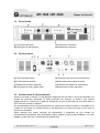
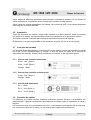
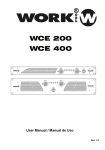
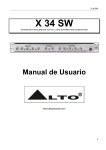
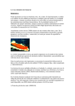
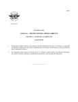
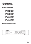
ETAPAS DE POTENCIA
POWER AMPLIFIERS
MT-1500
MT-3500
Manual de instalación y funcionamiento
Installation and operating instructions
MT-1500 / MT-3500
1.
2.
3.
Etapas de Potencia
INSTRUCCIONES DE SEGURIDAD ........................................................................... 2
CARACTERÍSTICAS ................................................................................................... 3
INSTALACIÓN Y FUNCIONAMIENTO........................................................................ 3
3.1
Desembalaje ......................................................................................................... 3
3.2
Montaje ................................................................................................................. 3
3.3
Panel frontal.......................................................................................................... 4
3.4
Panel posterior ...................................................................................................... 4
3.5
Precauciones de funcionamiento .......................................................................... 4
3.6
Instalación............................................................................................................. 5
3.7
Conexión de entradas ........................................................................................... 5
3.7.1
3.7.2
3.7.3
Entrada Jack conexión balanceada ...........................................................................5
Entrada Jack conexión no balanceada ......................................................................5
Entrada XLR balanceada ...........................................................................................5
3.8
Conexión de salidas.............................................................................................. 5
3.9
Conexión de la alimentación ................................................................................. 6
4. MODOS DE FUNCIONAMIENTO................................................................................ 6
4.1
Funcionamiento estéreo........................................................................................ 6
4.2
Funcionamiento paralelo....................................................................................... 6
5. INTERRUPTORES Y TECLAS DE CONTROL ........................................................... 6
5.1
Interruptor de alimentación AC y circuito de protección ........................................ 6
5.2
Potenciómetros de control de volumen de entrada ............................................... 6
5.3
Selector de modo de funcionamiento.................................................................... 7
5.4
Interruptor de unión chasis masa .......................................................................... 7
6. INDICADORES LUMINOSOS ..................................................................................... 7
6.1
LED PROTECT ..................................................................................................... 7
6.2
LED CLIP .............................................................................................................. 7
6.3
LEDS LEVEL - 6 / - 30 .......................................................................................... 7
6.4
LED POWER ........................................................................................................ 8
7. CARACTERÍSTICAS DE PROTECCIÓN .................................................................... 8
7.1
Sobrecalentamiento .............................................................................................. 8
7.2
Cortocircuito.......................................................................................................... 8
7.3
Voltaje de corriente continua................................................................................. 8
7.4
Frecuencias subsónicas........................................................................................ 8
7.5
Protección de conexión / desconexión.................................................................. 8
7.6
Protección de los altavoces .................................................................................. 9
8. ESPECIFICACIONES TÉCNICAS............................................................................... 9
MT-1500 / MT-3500 Versión 1.0
Página 1 de 9
MT-1500 / MT-3500
Etapas de Potencia
1. INSTRUCCIONES DE SEGURIDAD
¾ Guarde este manual para futuras consultas.
¾ Siga el manual de instrucciones para que el funcionamiento sea adecuado.
¾ No derrame agua u otros líquidos sobre la unidad. No utilice la unidad si le ha entrado líquido.
¾ Antes de conectar el equipo a la red eléctrica asegúrese de que éste se encuentra ajustado a
la tensión de suministro adecuada.
¾ No obstruya las entradas y salidas de ventilación. No utilice el amplificador en superficies que
impidan la circulación normal de aire entorno de la unidad, tales como camas, sofás, alfombras
o superficies similares.
¾ No use la unidad si el cable de alimentación está deteriorado o roto.
¾ Conecte siempre la unidad mediante un cable de corriente alterna con toma de tierra.
¾ No conecte la salida de otro amplificador en los canales de entrada.
¾ No conecte las salidas de línea en paralelo o en serie con otro amplificador.
¾ Asegúrese que el amplificador está apagado antes de conectarlo a la red eléctrica.
¾ No utilice estufas, radiadores u otras fuentes de calor cerca de la unidad.
¾ No conecte ningún terminal rojo a masa.
Nota: La información proporcionada por este manual no incluye detalles de diseño,
producción o variaciones en el equipo. Tampoco incluye posibles situaciones de riesgo
durante la instalación, funcionamiento o mantenimiento. Si usted necesita asistencia
especial más allá del manual, por favor contacte con nuestro servicio técnico.
MT-1500 / MT-3500 Versión 1.0
Página 2 de 9
MT-1500 / MT-3500
Etapas de Potencia
2. CARACTERÍSTICAS
•
Circuito de salida capaz de suministrar gran margen dinámico de voltaje con baja distorsión,
permitiendo que los transistores de salida trabajen de un modo más seguro y fiable.
•
Transformador toroidal con secundarios independientes especialmente diseñado para permitir
mayor regulación de volumen, mayor potencia y menor distorsión.
•
Circuito diseñado con funciones de protección por sobrecalentamiento, subidas de tensión,
cortocircuitos y ajuste automático de velocidad del ventilador.
•
Protección automática contra subidas de tensión que evita los picos de señal. Circuito pasa
altos diseñado para proteger los “woofer” en caso de picos de señal.
•
Amplificador de frecuencias bajas y medias y limitador de frecuencias elevadas. Relación
señal-ruido minimizada.
•
La serie MT está equipada con terminales XLR o jack de 6,35 mm. Dispone de dos modos de
funcionamiento: estéreo o paralelo.
•
Los terminales de salida de línea son de tipo SPEAKON y BANANAS.
3. INSTALACIÓN Y FUNCIONAMIENTO
3.1
Desembalaje
Abra cuidadosamente la caja de embalaje y compruebe que no haya ningún desperfecto. Cada
etapa de potencia es comprobada y verificada antes de salir de fábrica y debe llegar en perfectas
condiciones. Si usted encuentra algún daño, notifíquelo a la compañía de transportes
inmediatamente. Solamente el consignatario puede reclamar al transportista por un daño ocurrido
durante el envío. Asegúrese de guardar la caja y todos los materiales de embalaje para la
inspección del transportista. Es recomendable guardarlos aunque el amplificador haya llegado en
buenas condiciones. Usted podría necesitarlos en un futuro para enviar la unidad. Use sólo el
embalaje original de fábrica.
3.2
Montaje
La etapa de potencia está diseñada para su montaje en racks estándar de 19’’ con profundidad
suficiente. Ocupa dos unidades de altura y tiene cuatro agujeros en el panel frontal. Dispone de
escuadras posteriores para mejorar la sujeción del equipo, esenciales en instalaciones móviles y
recomendables en instalaciones permanentes. Debido a los cables y conectores del panel
posterior, será necesario un destornillador con ángulo o una llave Allen para fijar las escuadras en
las guías.
MT-1500 / MT-3500 Versión 1.0
Página 3 de 9
MT-1500 / MT-3500
3.3
Etapas de Potencia
Panel frontal
(1) Volúmenes de canal
(3) Orificios de ventilación
(2) Interruptor de alimentación
(4) Indicadores luminosos
3.4
Panel posterior
(5) Toma de alimentación
(9) Interruptor de modo de funcionamiento
(6) Fusible de alimentación
(10) Entradas balanceadas de señal
(7) Salidas de líneas de altavoces
(11) Selector de tensión de alimentación
(8) Interruptor de unión chasis masa
(12) Interruptor de filtro pasa altos
3.5
Precauciones de funcionamiento
Antes de conectar el equipo a la red eléctrica asegúrese de que éste se encuentra ajustado a la
tensión de suministro adecuada. El daño producido por conectar la unidad a una tensión
inadecuada no es cubierto por la garantía. Asegúrese de que el interruptor de encendido está en
OFF antes de conectar el aparato.
Es recomendable colocar los potenciómetros de ganancia al mínimo durante el encendido de la
unidad. De esa forma, se evitarán daños en los altavoces en el caso que haya un alto nivel de
señal en las entradas.
Utilice siempre una buena conexión de alimentación y asegúrese de que cumple los
requerimientos del aparato. Una alimentación pobre, debida a unos bornes oxidados o un cable
delgado, puede influir en el rendimiento del amplificador.
MT-1500 / MT-3500 Versión 1.0
Página 4 de 9
MT-1500 / MT-3500
Etapas de Potencia
Utilice cables de altavoces adecuados para minimizar la pérdida de potencia. En los bornes de
salida de altavoces, es preferible utilizar conectores a conectar el cable desnudo.
Utilice cables de entrada apantallados, de calidad, con conectores XLR y con buenas soldaduras
para asegurar la máxima fiabilidad.
3.6
Instalación
Todos los terminales de entrada y salida están situados en la parte posterior. Antes de conectar
una señal en la entrada, es imprescindible colocar los potenciómetros de ganancia al mínimo.
Se requiere personal cualificado para realizar el mantenimiento interno del aparato.
El fabricante no se hace responsable de los accidentes surgidos por el mal uso del equipo.
3.7
Conexión de entradas
Las entradas están disponibles en conectores XLR o jack estéreo, tienen una impedancia nominal
de 20 kΩ (10 kΩ desbalanceadas) y aceptan el nivel de señal de salida de la mayoría de
dispositivos del mercado. Pueden verse las distintas conexiones en las siguientes figuras:
3.7.1
Entrada Jack conexión balanceada
Punta - “Hot” (Señal +)
Anillo - “Cold” (Señal -)
Vástago - Masa
3.7.2
Entrada Jack conexión no balanceada
Punta - “Hot” (Señal +)
Vástago - Masa
3.7.3
Entrada XLR balanceada
Pin 1 - Masa
Pin 2 - “Hot” (Señal +)
Pin 3 - “Cold” (Señal -)
3.8
Conexión de salidas
Los altavoces se pueden conectar mediante conectores Speakon, Banana o directamente con
cable desnudo. Consulte los diámetros adecuados de los cables según la impedancia de carga y
longitud.
Los conectores rojos son considerados como “hot” y se conectan al polo positivo de los altavoces.
Los conectores negros son la masa y se conectan al polo negativo de los altavoces.
MT-1500 / MT-3500 Versión 1.0
Página 5 de 9
MT-1500 / MT-3500
Etapas de Potencia
¡Nunca conecte una salida “hot” (rojo) hacia una masa u otra salida “hot”!
¡Apague siempre el amplificador antes de realizar las conexiones!
3.9
Conexión de la alimentación
El consumo de corriente del amplificador varía según la carga aplicada, el nivel de salida y el tipo
de señal. El dato de potencia consumida por el equipo, se ha calculado considerando el
funcionamiento de los dos canales en condiciones nominales. La corriente máxima de salida de
cada amplificador se muestra en la tabla de características. En ningún caso es necesario
desmontar la cubierta del aparato. Sacarla representa un alto riesgo de descarga eléctrica.
4. MODOS DE FUNCIONAMIENTO
4.1
Funcionamiento estéreo
En modo estéreo los canales A y B funcionan de forma independiente. La señal de entrada del
canal A se amplifica y envía a la salida de canal A y la señal de entrada del canal B se amplifica y
envía a la salida de canal B.
Para seleccionar este modo de funcionamiento, apague el amplificador, ajuste los potenciómetros
de volumen al mínimo y ponga el selector de modo a la posición STEREO.
4.2
Funcionamiento paralelo
En modo paralelo la señal de entrada se enviará hacia los dos canales de salida sin necesidad de
ninguna conexión exterior. La señal debe aplicarse en la entrada del canal A y ajustarse con su
potenciómetro.
Para seleccionar este modo de funcionamiento, apague el amplificador, ajuste los potenciómetros
de volumen al mínimo y ponga el selector de modo en la posición PARALLEL.
5. INTERRUPTORES Y TECLAS DE CONTROL
5.1
Interruptor de alimentación AC y circuito de protección
El aparato dispone de una combinación de circuito de protección e interruptor de alimentación en
el panel frontal. Si en estado normal el interruptor pasa a posición de apagado, vuelva a colocarlo
en posición de encendido. En el caso de que no se mantenga en esa posición, consulte con el
servicio técnico.
5.2
Potenciómetros de control de volumen de entrada
Los potenciómetros de ganancia (uno para el canal A y otro para el canal B) están situados en el
panel frontal y regulan la atenuación de la señal en todos los modos de funcionamiento. Cuando
sea posible, fije los potenciómetros en la posición máxima para conseguir un rendimiento óptimo.
MT-1500 / MT-3500 Versión 1.0
Página 6 de 9
MT-1500 / MT-3500
5.3
Etapas de Potencia
Selector de modo de funcionamiento
El selector situado en el panel posterior determina si el amplificador funciona en modo estéreo o
en modo paralelo. No manipule el selector mientras el amplificador está en funcionamiento. Para
más información vea las secciones de Funcionamiento Estéreo y Funcionamiento Paralelo.
5.4
Interruptor de unión chasis masa
Para mayor seguridad y minimizar el ruido, el amplificador debería recibir la señal de masa desde
la toma de corriente. Siempre que sea posible, el equipo emisor de la señal de audio debe
compartir la masa con el amplificador. Algunas veces, es posible que se produzca un bucle de
masas. Si esto sucede, abra el puente de masa mediante el selector posterior. El puente conecta
eléctricamente la masa de la señal con la masa del chasis y de la toma de corriente. Si se quita el
puente, la masa de la señal se aísla completamente de la masa del chasis y de la toma de
corriente. No quite el puente si el amplificador y la fuente de sonido no comparten la misma masa.
6. INDICADORES LUMINOSOS
El equipo dispone de cinco indicadores LED por canal: PROTECT, CLIP, -6, -30 y POWER. Estos
LEDs indican el estado de operación de cada canal y advierten de posibles fallos.
6.1
LED PROTECT
El LED PROTECT se iluminará en rojo cuando en el canal se produzca un sobrecalentamiento. En
este caso el relé de salida de señal se abrirá y la línea de altavoces quedará desconectada. Esto
sucederá si el amplificador detecta un voltaje de corriente continua en la salida o durante el
encendido de la unidad (modo espera).
6.2
LED CLIP
El LED CLIP se iluminará en rojo tenue si la señal de entrada llega a la saturación, e irá
incrementando el brillo a medida que la saturación se haga más intensa. El LED parpadeará
rápido e intermitentemente si el nivel de señal se encuentra en el límite de saturación. Si se
mantiene encendido, indica que el amplificador está limitando o reduciendo la señal para prevenir
daños en los altavoces.
6.3
LEDS LEVEL - 6 / - 30
El LED -6 de color naranja indica que la señal de entrada tiene un nivel de señal de -6 dB o
superior. El LED -30 de color verde indica que la señal de entrada tiene un nivel de señal de
-30 dB o superior.
MT-1500 / MT-3500 Versión 1.0
Página 7 de 9
MT-1500 / MT-3500
6.4
Etapas de Potencia
LED POWER
El LED POWER de color verde indica que el amplificador está encendido, hay alimentación y el
sistema de ventilación está operacional.
7. CARACTERÍSTICAS DE PROTECCIÓN
La etapa de potencia está equipada con varios circuitos de protección capaces de evitar
cortocircuitos, saturaciones de señal, tensiones continuas y sobrecalentamientos. Cuando se
active una protección, se desconectará automáticamente la salida del canal correspondiente hasta
que se solucione el problema o se enfríe la etapa.
7.1
Sobrecalentamiento
En condiciones normales los ventiladores internos mantendrán el amplificador en perfecto
funcionamiento dentro del rango de temperatura habitual.
Si la temperatura de un canal supera los 90º C, éste se desconectará de la carga
automáticamente y el LED PROTECT se iluminará en rojo indicando un fallo por
sobrecalentamiento. El canal se reconectará automáticamente al bajar de 80º C.
7.2
Cortocircuito
En el caso de cortocircuito en la salida de línea, el circuito de protección será más sensible de lo
habitual, lo detectará inmediatamente y protegerá los transistores finales. El indicador LED
PROTECT se iluminará para indicarlo. Si el cortocircuito se mantiene, la protección térmica
desconectará la carga.
7.3
Voltaje de corriente continua
Al detectar voltaje de corriente continua en una salida de línea, ésta será inmediatamente abierta
para prevenir daños en los altavoces. El indicador LED PROTECT se iluminará.
7.4
Frecuencias subsónicas
El amplificador lleva incorporado un circuito de protección contra frecuencias subsónicas que
actúa por debajo de los 10 Hz en cada canal. Un circuito de protección también desconectará los
altavoces en caso de que haya una señal de una frecuencia muy elevada en la salida.
7.5
Protección de conexión / desconexión
Cuando se conecta el amplificador, primero se cargan las fuentes de alimentación y cuando están
estabilizadas, después de unos segundos, se conectan los altavoces. Cuando se desconecta la
alimentación, la señal de los altavoces se sincroniza con la señal de desconexión evitando
cualquier ruido.
MT-1500 / MT-3500 Versión 1.0
Página 8 de 9
MT-1500 / MT-3500
7.6
Etapas de Potencia
Protección de los altavoces
El amplificador protege automáticamente los altavoces contra los voltajes de corriente continua,
las frecuencias subsónicas y las altas frecuencias.
De todas formas, el usuario debe asegurase de que la potencia del amplificador no exceda los
límites de potencia de los altavoces.
8. ESPECIFICACIONES TÉCNICAS
Potencia de Salida
Distorsión RMS
Respuesta en Frecuencia
MT-1500
MT-3500
2 x 300 W a 2 Ω
2 x 700 W a 2 Ω
2 x 225 W a 4 Ω
2 x 500 W a 4 Ω
2 x 150 W a 8 Ω
2 x 350 W a 8 Ω
0,004 % a 1 kHz / 8 Ω
0,015 % a 1 kHz / 8 Ω
0,008 % a 1 kHz / 4 Ω
0,03 % a 1 kHz / 4 Ω
0,15 % a 20 Hz - 20 kHz / 8 Ω
0,15 % a 20 Hz - 20 kHz / 8 Ω
0,2 % a 20 Hz - 20 kHz / 4 Ω
0,2 % a 20 Hz - 20 kHz / 4 Ω
20 Hz - 20 kHz
0,2 dB
(8 Ω 1 W)
> 200 por debajo de 8 Ω
Factor Damping
≥ 110 dB
S/N
“Slew Rate”
38 V/µS
45 V/µS
Ganancia de Voltaje
AV = 45
AV = 68
0,775 V RMS
Sensibilidad de Entrada
Impedancia de Entrada
20 kΩ entradas balanceadas
10 kΩ entradas no balanceadas
Dimensiones (mm)
88 (alto) x 483 (ancho) x 480 (fondo)
Peso (kg)
17
24
LED de Alimentación: 2 x LED verde
LED de Señal: 2 x LED verde (-30 dB) +
Indicadores en el Panel
Frontal
2 x LED amarillo (-6 dB)
LED CLIP: 2 x LED rojo
LED PROTECT: 2 x LED rojo
Jack Señal Entrada
Entrada balanceada XLR (1 masa, 2 positivo, 3 negativo)
Selección de Modo
Estéreo / Paralelo
Frecuencia Inferior de
Corte
MT-1500 / MT-3500 Versión 1.0
Inferior a 30 Hz
Página 9 de 9
MT-1500 / MT-3500
1.
2.
3.
Power Amplifiers
SAFETY INSTRUCTIONS ........................................................................................... 2
FEATURES.................................................................................................................. 3
INSTALLATION AND OPERATION ............................................................................ 3
3.1
Unpacking ............................................................................................................. 3
3.2
Mounting ............................................................................................................... 3
3.3
Frontal panel ......................................................................................................... 4
3.4
Rear panel ............................................................................................................ 4
3.5
Operating precautions........................................................................................... 4
3.6
Installation............................................................................................................. 5
3.7
Connection input ................................................................................................... 5
3.7.1
3.7.2
3.7.3
Jack inputs (balanced signals) ...................................................................................5
Jack inputs (unbalanced signals) ...............................................................................5
XLR inputs (balanced signals) ...................................................................................5
3.8
Connecting outputs ............................................................................................... 5
3.9
Connecting power ................................................................................................. 6
4. OPERATING MODES.................................................................................................. 6
4.1
Stereo operation.................................................................................................... 6
4.2
Parallel operation .................................................................................................. 6
5. SWITCHES AND CONTROLS .................................................................................... 6
5.1
AC power switch circuit breaker ............................................................................ 6
5.2
Input volume potentiometers................................................................................. 6
5.3
Mode select switch................................................................................................ 6
5.4
Signal ground lift switch ........................................................................................ 7
6. INDICATORS............................................................................................................... 7
6.1
Protect LED........................................................................................................... 7
6.2
Clip LED................................................................................................................ 7
6.3
LEVEL LEDS -6 / -30 ............................................................................................ 7
6.4
POWER LED ........................................................................................................ 7
7. PROTECTION FEATURES ......................................................................................... 8
7.1
Overheat ............................................................................................................... 8
7.2
Short circuit ........................................................................................................... 8
7.3
DC voltage protection............................................................................................ 8
7.4
Subsonic frequencies............................................................................................ 8
7.5
Turn-on / turn-off protection .................................................................................. 8
7.6
Speaker protection ................................................................................................ 8
8. TECHNICAL SPECIFICATIONS ................................................................................. 9
MT-1500 / MT-3500 Version 1.0
Page 1 of 9
MT-1500 / MT-3500
Power Amplifiers
1. SAFETY INSTRUCTIONS
¾ Keep this owner’s manual for future reference.
¾ Follow instruction manual for proper operation.
¾ Do not spill water or other liquids on the unit. Do not operate the unit while standing in liquid.
¾ Make sure the power outlet conforms to the power requirements listed on the back of the unit.
¾ Do not block fan intake or exhaust ports. Do not operate the amplifier on a surface, which may
impede the normal flow of air around the unit, such as a bed, sofa, rug or similar surface.
¾ Do not use this unit if the electrical power cord is frayed or broken.
¾ Always operate the unit with the AC ground wire connected to the electrical system ground.
¾ Do not run the output of any amplifier channel back into another channels input.
¾ Do not parallel or series connect an amplifier output with any other amplifier output.
¾ Do not connect the output of the amplifier to any other voltage source, regardless of whether
the amplifiers turned on or off.
¾ Do not use the unit near stoves, heat registers, radiators, or other heat producing devices.
¾ Do not ground any red terminal.
Note: The information furnished in this manual does not include all of the details of design,
production, or variations of the equipment. Nor does it cover every possible situation that
may arise during installation, operation or maintenance. If you need special assistance
beyond the scope of this manual, please contact our technical service.
MT-1500 / MT-3500 Version 1.0
Page 2 of 9
MT-1500 / MT-3500
Power Amplifiers
2. FEATURES
•
Unique output circuit providing a wider voltage dynamic range with lower distortion, creating a
safe environment for power output transistors, enhancing reliability.
•
Specially designed separate ring-shaped transformer with large volume, providing more power
and lower distortion.
•
Circuit design providing overheating protection, power surge limiter, short circuit protection,
and automatic speed adjusting cooling fan control.
•
Auto power surge protection ensures no surf impulse. Low frequency cutting circuit designed
to protect woofer in case of power crest.
•
Advanced low and mid range frequency booster and high range limiter design. Signal to noise
ratio minimized.
•
MT series built with XLR and 6.35 socket, providing two choices of operation: stereo and
parallel.
•
Output terminals include SPEAKON and BINDING POST.
3. INSTALLATION AND OPERATION
3.1
Unpacking
Carefully open the shipping carton and check for any noticeable damage. Every amplifier is
completely tested and inspected before leaving the factory and should arrive in perfect condition. If
you find any damage, notify the shipping company immediately. Only the consignee may institute a
claim with the carrier for damage incurred during shipping. Be sure to save the carton and all
packing materials for the carrier’s inspection. It is a good idea to save the carton and packing
material even if the amplifier has arrived in good condition. Should you ever need to ship the unit,
use only the original factory packing.
3.2
Mounting
The power amplifier will mount in standard 19-inch racks having sufficient depth. The amplifier is
two rack spaces high. Four front panel mounting holes are provided. Rear mounting ears are also
provided for additional support, which is essential in non-permanent installations like mobile or
touring sound systems, but recommended for permanent installations as well. Because of the
cables and connectors on the rear panel, a right angle or offset screwdriver or hex key will make it
easier to fasten the rear mounting ears to the rails.
MT-1500 / MT-3500 Version 1.0
Page 3 of 9
MT-1500 / MT-3500
3.3
Frontal panel
(1) Channel volumes
(3) Air in take grill
(2) Power switch
(4) Front panel indicators
3.4
Power Amplifiers
Rear panel
(5) Power cord plug
(9) Operation modes switch
(6) Power fuse
(10) Balanced phone jacks inputs
(7) Binding post output connectors
(11) Power voltage selector switch
(8) Signal ground lift barrier strip
(12) Low frequency bypass/sub filter switch
3.5
Operating precautions
Make sure that the AC mains voltage is the same as printed on the rear of the amplifier. Damage
caused by connecting the amplifier to improper AC voltage is not covered by the amplifier
warranty. Make sure the power switch is OFF before making system connections or plugging.
It is always a good idea to have the gain controls turned down during power-up to prevent speaker
damage if there is a high signal level at the inputs.
Always use a quality power outlet, and make sure it meets the power requirements. Low quality
power outlet, such as oxidized spring blades in the outlet or to small cable connected to the outlet,
etc, will have an adverse effect on the performance of the amplifier.
Use proper speaker cables to minimize the power loss in the cables. It is better to use spade lugs
than bare wire to connect the speaker system to the red binding posts.
MT-1500 / MT-3500 Version 1.0
Page 4 of 9
MT-1500 / MT-3500
Power Amplifiers
Use good quality shielded input cables and XLR plugs, along with good soldering technique, to
ensure trouble free reliability.
3.6
Installation
All input sockets and output posts are located at the rear panel. Special attention is needed when
selecting Signal Socket, turn gain control to the minimum.
Qualified service personnel are required for all servicing of internal parts.
Manufacturer is not responsible for any accidents arising from a user misuse.
3.7
Connection input
The balanced phone jack inputs have a nominal impedance of 20 kΩ (10 kΩ unbalanced wiring)
and will accept the line level output of most devices. Three-pin female XLR connectors are also
available. Next figures provide examples of recommended connection techniques for each type of
signal source.
3.7.1
Jack inputs (balanced signals)
Tip - “Hot” (+ signal)
Ring - “Cold” (- signal)
Sleeve - Ground
3.7.2
Jack inputs (unbalanced signals)
Tip - “Hot” (+ signal)
Sleeve - Ground
3.7.3
XLR inputs (balanced signals)
Pin 1 - Ground
Pin 2 - “Hot” (+ signal)
Pin 3 - “Cold” (- signal)
3.8
Connecting outputs
Speakers can be connected using Banana plugs, Speakon plugs, or bare wire to the binding posts
on the rear panel of the amplifier. Consult the wire gauges for different load impedances and cable
lengths.
The red binding posts are considered hot, connecting to the positive poles of speakers, while the
black binding posts are signal ground, connecting to the negative poles of speakers.
Never connect a hot (red) output to ground or to other hot outputs! Always turn off the amplifier
before making connections!
MT-1500 / MT-3500 Version 1.0
Page 5 of 9
MT-1500 / MT-3500
3.9
Power Amplifiers
Connecting power
Power demand from the AC mains depends on many factors (including its load, output level, and
the crest factor of its program material). The amplifier power requirement is rated under typical
music conditions. Maximum current draw for each amplifier is listed in the specifications section. In
any case, it’s no necessary to remove the top cover. Removing it can expose dangerous voltages
and shock hazards.
4. OPERATING MODES
4.1
Stereo operation
For stereo mode, both channels operate independently of each other. Thus, a signal at channel A
input is amplified and broadcasted to channel A output, while a signal at channel B input is
amplified and broadcasted to channel B output.
Before connection, turn off the power amplifier, minimize the volume gain potentiometers of both
channels and set the mode switch to STEREO position.
4.2
Parallel operation
In parallel mode, one signal can be sent to both channels without external connection. The audio
signal is broadcasted from channel A input to channel A and channel B outputs. The volume is
controlled by means of channel A potentiometer.
Before connection, turn off the power amplifier, minimize the volume gain potentiometers of both
channels and set the mode switch to PARALLEL position.
5. SWITCHES AND CONTROLS
5.1
AC power switch circuit breaker
The amplifier has a combination AC switch/circuit breaker on the front panel. If the switch shuts off
during normal use, push it back to the ON position once. If it will not stay on, the amplifier needs
servicing.
5.2
Input volume potentiometers
The input potentiometer controls (one for channel A, one for channel B) are located on the front
panel and adjust the gain in all modes. Whenever possible, set the potentiometers fully clockwise
to maintain optimum system headroom.
5.3
Mode select switch
The rear panel mode select switch determines whether the amplifier is in stereo or parallel mode.
Do not operate the mode select switch while the amplifier is on. See the sections about stereo and
parallel mode for more information.
MT-1500 / MT-3500 Version 1.0
Page 6 of 9
MT-1500 / MT-3500
5.4
Power Amplifiers
Signal ground lift switch
For safety and to minimize noise, the amplifier should receive its ground from the line cord.
Whenever possible, the signal source equipment should share the same AC ground as the
amplifier. In some cases, however, this may result in a ground loop. If this happens, remove the
ground lift jumper with the rear panel switch. This jumper electrically connects the signal ground to
the chassis / AC ground. If the jumper is removed, the signal ground is lifted and completely
isolated from the chassis / AC ground. Do not remove the jumper if the amplifier and the signal
source equipment are not on the same AC ground.
6. INDICATORS
The amplifier has five LED indicators in each channel: PROTECT, CLIP, -6, -30 and POWER.
These LEDs displays the operating status and warn about possible abnormal conditions.
6.1
Protect LED
When the red PROTECT LED lights red indicates that the channel has overheated, the channel’s
output relay is open, and the speaker has been disconnected. This will happen if the amplifier
senses a DC voltage at its output or when the unit is powered up and it is in the turn-on delay.
6.2
Clip LED
A channel’s red CLIP LED will light dimly at the onset of clipping and increase in brilliance, as
clipping becomes more and more severe, staying on until the clipping ceases. If the LED is flashing
quickly and intermittently, the channel is just at the clip threshold level, while a steady, bright glow
means the amplifier is clip limiting, or reducing gain to prevent severely clipped waveforms
reaching loudspeakers.
6.3
LEVEL LEDS -6 / -30
The orange -6 LED lights up when the channel produces an output signal of about -6 dB signal
level. The green -30 LED lights up when the channel produces an output signal of about -6 dB
signal level.
6.4
POWER LED
This indicator lights when the amplifier has been turned on, AC power is available and the lowvoltage power supply and fan are operational.
MT-1500 / MT-3500 Version 1.0
Page 7 of 9
MT-1500 / MT-3500
Power Amplifiers
7. PROTECTION FEATURES
Each power amplifier incorporates several circuits to protect both themselves and the
loudspeakers against short and open circuits, DC voltages and overheating. When the protection
mode is activated, the channel’s output relay disconnects the speaker load until the problem is
corrected or the amplifier cools down.
7.1
Overheat
The internal fan will keep the amplifier operating well within its intended temperature range under
all normal conditions. When a channel’s heat sink temperature reaches 90 ºC, which may indicate
an obstructed air supply, clogged air filter, etc, the channel will disconnect its load. Normal
operation will resume automatically once it cools to 80 ºC. During this time, the channel’s
PROTECT LED will light.
7.2
Short circuit
If an output is shorted, the protection circuit will be more sensitive than in the normal protection
situation and will protect the channel’s output transistors from over current stress. The channel’s
PROTECT LED will light. If the short circuit remains, the channel will eventually thermally protect
itself by disconnecting the load.
7.3
DC voltage protection
If an amplifier channel detects DC voltage at its output, the circuit will immediately open speaker’s
line to prevent loudspeakers damage. The channels PROTECT LED will light.
7.4
Subsonic frequencies
The power amplifier has a built-in subsonic frequency protection circuit, cornered at 10 Hz, for
each channel. Also a special high frequency protection automatically disconnects speakers when
excessive high frequency energy appears at the output.
7.5
Turn-on / turn-off protection
At power up speakers are disconnected, the power supplies charge for about few seconds and
stabilize, the speakers are then connected. When power is removed, speaker loop is synchronized
with the turn off signal, therefore no thumps or pops are heard.
7.6
Speaker protection
The power amplifier automatically protects speakers from DC voltages, subsonic signals and
excessive high frequency signals; however, the user must be aware that the amplifier power does
not exceed the speaker’s power capabilities.
MT-1500 / MT-3500 Version 1.0
Page 8 of 9
MT-1500 / MT-3500
Power Amplifiers
8. TECHNICAL SPECIFICATIONS
Output Power
RMS Distortion
Frequency Response
MT -1500
MT -3500
2 x 300 W at 2 Ω
2 x 700 W at 2 Ω
2 x 225 W at 4 Ω
2 x 500 W at 4 Ω
2 x 150 W at 8 Ω
2 x 350 W at 8 Ω
0,004 % at 1 kHz / 8 Ω
0,015 % at 1 kHz / 8 Ω
0,008 % at 1 kHz / 4 Ω
0,03 % at 1 kHz / 4 Ω
0,15 % at 20 Hz - 20 kHz / 8 Ω
0,15 % at 20 Hz – 20 kHz / 8 Ω
0,2 % at 20 Hz - 20 kHz / 4 Ω
0,2 % at 20 Hz - 20 kHz / 4 Ω
20 Hz - 20 kHz
0,2 dB
(8 Ω 1 W)
> 200 under 8 Ω
Damping Factor
≥ 110 dB
S/N
Slew Rate
38 V/µS
45 V/µS
Voltage Gain
AV = 45
AV = 68
Input Sensitivity
Under 0,775 V RMS output
Input Impedance
20 kΩ for balanced inputs
10 kΩ for unbalanced inputs
Dimensions (mm)
88 (height) x 483 (width) x 480 (depth)
Weight (kg)
17
Front Panel Indicators
24
POWER LED: 2 x green LED
LEVEL LED: 2 x green LED (-30 dB) + 2 x yellow LED (-6 dB)
CLIP LED: 2 x red LED
PROTECT LED: 2 x red LED
Signal Input Jack
Mode Selection
Low Frequency Cut
MT-1500 / MT-3500 Version 1.0
XLR balanced input (1 ground, 2 positive, 3 negative)
Stereo / Parallel
Minus 30 Hz
Page 9 of 9