1
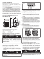
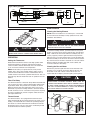
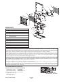
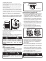
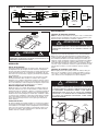
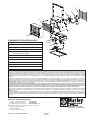
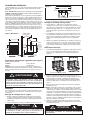
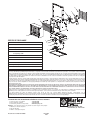
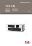
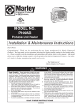
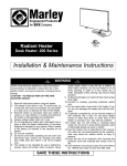
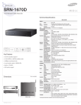
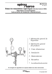
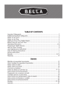
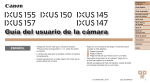
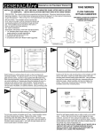
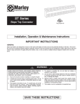
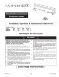
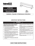
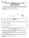
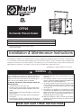
9900268
CFP25
Horizontal Plenum Heater
CFP25 SPECIFICATIONS- Ratings @ 0.20” SP
VOLTS
240
208
HZ
KW
PHASE
BTUH
CFM
50 / 60
1.9
1
6398
130
50 / 60
2.5
1
8530
(Thermostat temperature range : 40°F to 90°F)
* Includes motor amps.
150
FPM
RISE
AMPS*
1880
46°F
9.42
1880
60°F
10.7
Installation & Maintenance Instructions
Dear Owner,
Congratulations! Thank you for purchasing this new heater manufactured by Marley Engineered Products. You have made
a wise investment selecting the highest quality product in the heating industry. Please carefully read the installation and
maintenance instructions shown in this manual. You should enjoy years of efficient heating comfort with this product from
Marley Engineered Products... the industry’s leader in design, manufacturing, quality and service.
... The Employees of Marley Engineered Products
WARNING
Read Carefully - These instructions are written to help you
prevent difficulties that might arise during installation of
heaters. Studying the instructions first may save you considerable time and money later. Observe the following procedures, and cut your installation time to a minimum.
TO REDUCE THE RISK OF FIRE, ELECTRIC SHOCK OR
HEATER FALLING:
1. Use minimum 75ºC copper wire only.
2. Verify the power supply voltage coming to heater matches the ratings printed on heater nameplate before energizing.
3. Heater air flow must be directed parallel to, or away from
adjacent walls.
4. Observe wall, floor, and ceiling clearance requirements.
See Figure 1
5. All wiring must conform to national and local electrical
codes and the heater must be grounded as a precaution
!
against possible electrical shock. Heater circuit must be
protected with proper over current protection. See unit
nameplate.
6. The mounting structure and the anchoring hardware
must be capable of reliably supporting the weight of the
heater and if used, the mounting bracket.
7. All electrical power must be disconnected at the main
service box before installing, inspecting, cleaning or servicing the heater. This is a precaution to prevent possible
electrical shock.
8. This heater is not suitable for use in hazardous location
as defined by the National Fire Protection Association
(NFPA). this heater has hot and arcing (sparking) parts
inside. Do not use in areas where gasoline, paint, or
flammable liquids are used or stored.
10. Improper installation or failure to follow the procedures
outlined in this instruction manual can result in serious
electrical shock.
READ AND SAVE THESE INSTRUCTIONS
GENERAL INFORMATION
Model CFP25 is designed, tested and Listed by Intertek
Testing Services NA, Inc. (ETL/C-ETL Listing Mark) to comply
with the following standards:
USA: ANSI/UL 1995 titled “Heating and Cooling Equipment”
Canada: CSA C22.2 No. 236-05, third edition titled “Heating
and Cooling Equipment”
This unit is specifically designed and approved for freeze protection installations into a concealed space and other areas not
readily accessible. Typical applications include plenums and
associated plenum spaces (such as areas above a finished
ceiling that contain utilities), crawl spaces, water closets and
other concealed locations where freeze protection is required.
Note: rated static pressure is 0.20” sp . This unique heater is
provided with a set of normally open contacts that can supply a
line voltage signal to an alarm device if desired to provide early
notice if for any reason the heater cycles off on its built-in over
temperature safety control. This can provide an early notification to allow for repairs BEFORE a freeze up occurs
Figure 1 Dimension Data
14 in. (356 mm)
MINIMUM DISTANCE
TO WALL
13 in.
(330.2 mm)
14 in.
(356 mm)
1
5 /2 in.
(140 mm)
MOUNTING
LOCATION
MINIMUM
DISTANCE
FROM
DISCHARGE
TO ANY
OBJECT
24 in.
(610 mm)
7 3/8 in.
(187 mm)
INTAKE
121/2 in.
(318 mm)
0 in.
(0 mm)
FRONT VIEW
1 3/4 in.
(45 mm)
1
/2 in.,3/4 in. (2)
(13 mm, 20 mm)
SIDE VIEW
Minimum Installation Clearances (See Figure 1)
SIDES, TOP AND BOTTOM
0 IN.
REAR:
7-3/8 in. (187 mm)
FRONT:
24 in. (610 mm)
Note: To access field wiring and heater controls requires the
bottom panel door open as shown in Fig. 3. Consideration
must be given to provide access to this
M panel.
!
WARNING
TURN OFF ALL ELECTRICAL POWER TO UNIT BEFORE
PERFORMING ANY MAINTENANCE OR SERVICE ON UNIT.
(UNLESS SPECIFIC TESTS REQUIRE ELECTRICAL
SUPPLIES.) FAILURE TO TAKE THIS PRECAUTION MAY
RESULT IN PERSONAL INJURY OR DEATH DUE TO
ELECTRICAL SHOCK.
MOUNTING
This heater can be mounted using the mounting bracket
provided with the heater or it may be mounted using the 1/2” 13NC threaded hole provided on the top of the heater.
Mounting The Heater With Bracket
1. Remove the bracket from the heater and position to the
desired mounting location (see Figure 2). Securely attach to
the building structure using appropriate hardware (supplied
by others).
!
CAUTION
TWO EACH, MIN. 3/8” DIA. MOUNTING BOLTS (OR LAG BOLTS),
FLAT WASHERS, LOCK WASHERS, AND NUTS AS NECESSARY MUST BE USED SO THE HEATER WILL NOT FALL - SEE
WARNING NO. 6.
Figure 2
CEILING JOIST
WASHER
BRACKET
3/ 8"
DIAGONAL
LAG BOLT
Double-Screw Mounting
2. Attach heater to bracket using the keyhole slots in bracket
and bolts provided with heater. Position heater as desired
and tighten bolts.
Mounting The Heater With Threaded Rod
1. A 1/2”-13NC threaded hole is provided in top of heater
enclosure for mounting the heater if desired. Optional
mounting brackets are available from your electrical distributor for use with this heater. If one of these brackets is
to be used, refer to the instructions provided with the
bracket.
2. If a threaded rod is used, it must be securely attached to
the building structure using appropriate brackets, washers,
nuts and lock washers to secure the heater properly and
prevent it from falling (see Warning No. 6, page 1).
3. When installing threaded rod into heater, make sure rod is
inserted approximately 1” into heater to assure all threads
are engaged. In addition, a 1/2” nut should be used as a
jam nut to prevent the heater from rotating during operation.
Connecting the Power
1. To connect the power to the heater, simply remove the
three screws from the bottom of the unit. This allows the
cover to be removed, providing access to the electrical
wiring and connectors. (See Fig. 3)
Figure 3
REMOVE SCREW TO OPEN DOOR
2. Attach the cable connectors to the unit and slide 10 gauge
wire or appropriate size for amperage marked on the
heater nameplate and length of run per NEC (National
Electrical Code) through the cable connector. Pull enough
of the wire through the connector to work with when making the connections.
3. Connect the wire to the power terminal block located in
the base of the heater (See Figures 4 and 5).
Note: This unit is provided with two 1/4” male quick connect
terminals (see Wiring Diagram, Figure 4) marked as Alarm
1 and Alarm 2, to allow for an external alarm to be connected to the unit if desired. This option can provide notification if the heater overheats and cycles on the thermal
over-temperature limit. Each terminal (Alarm 1 or Alarm 2)
will provide 120 volts to ground. Connection to both Alarm
1 and Alarm 2 terminals will supply line voltage (208 or
240V) to the alarm.
!
CAUTION
TO PREVENT DAMAGE TO THE ALARM DEVICE, IT MUST BE
SUITABLE FOR VOLTAGE AS NOTED ABOVE.
4. Close the wiring compartment and replace the screw and
turn on the power at the main service.
Figure 4 Wiring Diagram
BLACK
CONTACTOR DPDT
BLACK
BLACK
L1
L2
RED
TAP BOARD
ALARM L1
BLACK
RED
RED
FAN DELAY
THERMOSTAT
BK
BK
RD
RD
MOTOR
ALARM L2
HEATING ELEMENT
BLACK
PRIMARY LIMIT
BLACK
RED
Figure 5
BOTTOM
VIEW
L2
MAINTENANCE
Cleaning the Heating Element
NOTE: Heater is installed in a concealed space. Unit should
be checked at least annually to verify operation and to clean
fan blades and elements.
G
Ba REE
re N
Co
pp
e
(or
L1
!
CAUTION
USE CARE TO PREVENT DAMAGE TO INTERNAL HEATER
WIRING. MAKE SURE ALL CONNECTIONS REMAIN TIGHT.
OPERATION
Setting the Thermostat
Rotate thermostat knob clockwise to the high position. After
desired temperature is obtained, rotate thermostat knob
counter-clockwise until the thermostat clicks off. Heater will
cycle on and off to maintain room temperature.
NOTE: The first time you operate the unit, it may smoke
slightly. This is due to the residual cleaning agents used to
clean the element when the heater is manufactured. This is
normal and does not indicate a problem with the unit. This condition will stop after the heater has been in operation for a few
minutes.
Timed Fan Delay
The CFP25 heater has a timed fan delay. When the thermostat
calls for heat, fan action is delayed momentarily until the heating elements warm. This prevents the circulation of cold air.
When the heater raises the temperature of the room to the
thermostat set point, the heating element is turned off but the
fan will continue to run for a short time. This prevents exposing
the unit to residual heat, provides a higher comfort level and
prolonged element life.
WARNING
!
ITE
r)
WH
POWER
TERMINAL
BLOCK
BLA
CK
1609-2131-000
REV. A
TO PREVENT POSSIBLE ELECTRICAL SHOCK, ALL
POWER MUST BE SHUT OFF AT THE MAIN SERVICE
BEFORE INSPECTING OR CLEANING.
To clean the heating element, open the bottom access panel
(Figure 3) and disconnect the two element wires from the time
delay . Remove the front outlet cabinet assembly by way of 4
screws ( Figure 6). Remove grille from back inlet (motor/fan
grille) by way of 4 screws. Remove the 4 screws mounting the
element assembly to the fan deck and remove element assembly. Remove dust or lint with a soft brush or a vacuum cleaner.
Replace element assembly, inlet grille, outlet cabinet, and
reconnect element to time delay.
Cleaning the Fan and Motor
Remove the protective grille from the rear of the heater. This
provides access to the fan and motor. Wipe off the fan and
motor with a soft cloth or brush. The fan motor does not
require lubrication. Replace protective grille. (See Figure 6.)
!
CAUTION
USE CARE TO PREVENT DAMAGE TO INTERNAL HEATER
WIRING WHEN CLEANING ELEMENT. MAKE SURE ALL
CONNECTIONS REMAIN TIGHT AND ALL WIRING IS ROUTED AWAY FROM ELEMENT FINS WHEN REASSEMBLING
THE UNIT. ALLOWING WIRING TO TOUCH THE ELEMENT
FINS COULD RESULT IN A FIRE HAZARD.
Figure 6
Thermal Cutout
The CFP25 heater is also equipped with a thermal cutout
which will automatically shut off the heater in the event of overheating. The heater will turn on when the operating temperature returns to normal. Should the unit overheat and activate
the thermal cutout cycle, the cause of the overheating should
be determined before further operation.
PROTECTIVE GRILL
SCREWS (4)
FRONT CABINET
ASSEMBLY
SCREWS (4)
FAN AND MOTOR
9
4
1
10
9
REPAIR PARTS
REF
1
2.
3
4.
DESCRIPTION
1210-2017-000
High Limit
1
1414-2037-000
Time Delay
Motor 6 watt unit bearing
7.
Thermostat
9.
10.
PART NUMBER
1
Relay
8.
QTY
Fan Blade
5.
6.
5
1
1
1
3900-2008-000
5823-0004-000
Thermostat Knob
1
3301-2053-000
Element
2
–
6
7
8
1414-2038-000
1
Wire Guard
2
410171003
Terminal Block
1
3
5813-2091-000
312056-000
302006807
LIMITED WARRANTY
All products manufactured by Marley Engineered Products are warranted against defects in workmanship and materials for one year from date of installation, except
heating elements which are warranted against defects in workmanship and materials for five years from date of installation. This warranty does not apply to damage from
accident, misuse, or alteration; nor where the connected voltage is more than 5% above the nameplate voltage; nor to equipment improperly installed or wired or maintained in violation of the product’s installation instructions. All claims for warranty work must be accompanied by proof of the date of installation.
The customer shall be responsible for all costs incurred in the removal or reinstallation of products, including labor costs, and shipping costs incurred to return products
to Marley Engineered Products Service Center. Within the limitations of this warranty, inoperative units should be returned to the nearest Marley authorized service center or the Marley Engineered Products Service Center, and we will repair or replace, at our option, at no charge to you with return freight paid by Marley. It is agreed that
such repair or replacement is the exclusive remedy available from Marley Engineered Products.
THE ABOVE WARRANTIES ARE IN LIEU OF ALL OTHER WARRANTIES EXPRESSED OR IMPLIED. AND ALL IMPLIED WARRANTIES OF MERCHANTABILITY AND
FITNESS FOR A PARTICULAR PURPOSE WHICH EXCEED THE AFORESAID EXPRESSED WARRANTIES ARE HEREBY DISCLAIMED AND EXCLUDED FROM
THIS AGREEMENT. MARLEY ENGINEERED PRODUCTS SHALL NOT BE LIABLE FOR CONSEQUENTIAL DAMAGES ARISING WITH RESPECT TO THE PRODUCT, WHETHER BASED UPON NEGLIGENCE, TORT, STRICT LIABILITY, OR CONTRACT.
Some states do not allow the exclusion or limitation of incidental or consequential damages, so the above exclusion or limitation may not apply to you. This warranty
gives you specific legal rights, and you may also have other rights which vary from state to state.
For the address of your nearest authorized service center, contact Marley Engineered Products in Bennettsville, SC, USA, at 1-800-642-4328. Merchandise returned to
the factory must be accompanied by a return authorization and service identification tag, both available from Marley Engineered Products. When requesting return authorization, include all catalog numbers shown on the products.
HOW TO OBTAIN WARRANTY SERVICE AND
WARRANTY PARTS PLUS GENERAL INFORMATION
1. Warranty Service or Parts
2. Purchase Replacement Parts
3. General Product Information
1-800-642-4328
1-800-654-3545
www.marleymep.com
Note: When obtaining service always have the following:
1. Model number of the product
2. Date of manufacture
3. Part number or description
Part No. 5200-2816-000
470 Beauty Spot Rd. East
Bennettsville, SC 29512 USA
PPD 062
4/07
9900268
CFP25
Calefactor horizontal para cámara
ESPECIFICACIONES DEL CFP25 – Valores nominales @ presión estática = 0.20”
TENSIÓN
(VOLTS)
FRECUENCIA
(Hz)
POTENCIA
(KW) FASES
POTENCIA
CALÓRICA
(BTU/h)
CAUDAL DE AIRE
(PIES CÚBICOS
POR MINUTO)
VELOCIDAD
DEL AIRE
(PIES POR
MINUTO)
SOBREELEVACIÓN
DE TEMPERATURA
CONSUMO
(AMPERES)*
240
50 / 60
2.5
1
8530
150
1880
33 °C (60°F)
10.7
208
50 / 60
1.9
1
6398
130
1880
26 °C (46°F)
9.42
(Intervalo de temperaturas del termostato: 4.4 ºC [40 ºF] a 32.2 ºC [90 ºF])
* Incluye el consumo del motor.
Instrucciones de instalación y mantenimiento
Estimado propietario:
¡Felicitaciones! Gracias por comprar este nuevo calefactor fabricado por Marley Engineered Products. Al seleccionar el producto de más
alta calidad de la industria de calefacción, usted ha hecho una sabia inversión. Por favor, lea cuidadosamente las instrucciones de instalación
y mantenimiento incluidas en este manual. Así podrá disfrutar de años de calefacción confortable y eficiente con este producto de Marley
Engineered Products... el líder de la industria en diseño, fabricación, calidad y servicio.
... Los empleados de Marley Engineered Products
ADVERTENCIA
Lea cuidadosamente – Estas instrucciones están escritas para
ayudarle a superar las dificultades que podrían aparecer
durante la instalación de calefactores. El estudio previo de estas
instrucciones puede ahorrarle considerable tiempo y dinero en
el futuro. Observe los procedimientos que siguen, y reducirá el
tiempo de instalación a un mínimo.
Para reducir el riesgo de incendio, choque eléctrico o caída
del calefactor:
1.
2.
3.
4.
Utilice únicamente cables de cobre que soporten 75 ºC como
mínimo.
Antes de aplicar alimentación eléctrica, verifique que la tensión de
alimentación provista al calefactor sea compatible con la tensión
nominal impresa en la placa de características del mismo.
La circulación de aire del calefactor debe dirigirse paralelamente a
las paredes adyacentes, o en dirección opuesta a ellas.
Observe los requisitos de espacio libre en relación con las paredes,
piso y cielorraso. Vea la Figura 1
5.
!
Todo el conexionado debe hacerse de conformidad con los códigos
eléctricos nacionales y locales, y el calefactor debe estar conectado
a tierra, como precaución contra la posibilidad de choque eléctrico.
El circuito del calefactor debe estar protegido adecuadamente
contra sobrecorrientes. Vea la placa de características de la unidad.
6. La estructura de montaje y los accesorios de anclaje deben ser
capaces de soportar confiablemente el peso del calefactor y, en
caso de utilizarlo, del soporte de montaje.
7. Antes de instalar, inspeccionar, limpiar o prestar servicio al
calefactor debe desconectarse toda la alimentación eléctrica en el
tablero principal de servicio. Esta es una precaución tendiente a
evitar un posible choque eléctrico.
8. Este calefactor no es apto para su empleo en lugares peligrosos
según la definición de la Asociación Nacional de Protección contra
Incendio (NFPA) de los Estados Unidos. Tiene en su interior piezas
calientes, y piezas en las que se producen arcos (chispas). No lo
utilice en áreas en las que se utilice o almacene gasolina, pintura o
líquidos inflamables.
10. Una instalación incorrecta, o la falta de cumplimiento de los
procedimientos indicados en este manual de instrucciones, pueden
provocar un grave choque eléctrico.
GUARDE ESTAS INSTRUCCIONES
INFORMACIÓN GENERAL
El modelo CFP25 está diseñado, probado y registrado por Intertek
Testing Services NA, Inc. (Marca de Registro ETL/C-ETL) para cumplir
con las normas siguientes:
EE. UU.: ANSI/UL 1995, titulada ‘Equipos de calefacción y refrigeración’
Canadá: CSA C22.2 Nº 236-05, tercera edición, titulada “Equipos de
calefacción y refrigeración”
Esta unidad está diseñada y aprobada específicamente para instalaciones de protección contra la congelación en espacios ocultos y otras
áreas de acceso difícil. Sus aplicaciones típicas comprenden cámaras y
sus espacios asociados (como las zonas que contienen instalaciones y
están encima de un cielorraso terminado), espacios bajo el piso, servicios sanitarios y otros lugares ocultos en los que se necesite una protección contra la congelación.
Nota: la presión estática nominal es 0.20”. Este calefactor exclusivo se
suministra con un conjunto de contactos normalmente abiertos que
pueden suministrar, si se desea, una señal de tensión de línea a un dispositivo de alarma, para dar un aviso anticipado si por alguna razón el
calefactor hace ciclos de activación de su control integrado de seguridad
de sobretemperatura. Esto puede brindar una notificación temprana para
permitir hacer reparaciones ANTES de que se produzca la congelación.
Figura 1 Dimension Data
14 in. (356 mm)
121/2 in.
(318 mm)
0 in.
(0 mm)
VISTA
FRONTAL
FRONT
VIEW
DISTANCIA
A LA
DISTANCE
MINIMUMMÍNIMA
PARED
TO
WALL
13"in.
13
mm)
(330.2 MM)
(330,2
14 in.
(356 mm)
51/2 in.
(140 mm) UBICACIÓN PARA
MOUNTING
EL MONTAJE
LOCATION
MINIMUM
DISTANCIA
DISTANCE
MÍNIMA
7 3/8 in.
FROMDE LA
DESCARGA A
(187 mm)
DISCHARGE
CUALQUIER
TO ANY
OBJECT
OBJETO
ADMISIÓN
INTAKE
2424"in.
(610
(610mm)
MM)
1 3/4 in.
(45 mm)
1/2 in.,3/4 in. (2)
(13 mm, 20 mm)
Figura 2
VIGUETA
DEL CIELORRASO
CEILING
JOIST
ARANDELA
WASHER
SOPORTE
BRACKET
3/8" DIAGONAL
DE
TIRAFONDO
9.5LAG
mmBOLT
(3/8”)
DEL TRAVESAÑO
Montaje con dos tornillos
que están en el soporte y los pernos provistos con el calefactor.
Coloque el calefactor en la posición deseada y apriete los pernos.
Montaje del calefactor con varilla roscada
1. En la cara superior del gabinete del calefactor se proporciona un agujero roscado de ½”-13NC para el montaje del mismo, si fuera necesario. Puede obtener, de su distribuidor de productos eléctricos,
soportes de montaje opcionales para el uso con este calefactor. Si
va a utilizar alguno de estos soportes, consulte las instrucciones que
se proporcionan con el mismo.
2. Si se utiliza una varilla roscada, debe fijarse firmemente a la estructura del edificio mediante los soportes, arandelas, tuercas y arandelas de presión adecuadas, para sujetar correctamente el calefactor y
evitar que se caiga (vea la Advertencia Nº 6, página 1).
3. Cuando instale la varilla roscada en el calefactor, asegúrese de insertarla aproximadamente 25 mm (1”) para que todas las roscas hagan
contacto. Además debe utilizarse una tuerca de 13 mm (1/2”) como
contratuerca, para evitar que el calefactor gire durante la operación.
Conexión de la alimentación eléctrica
1. Para conectar la alimentación eléctrica al calefactor, simplemente
quite los tres tornillo del fondo de la unidad. Esto permite que la
panel inferior está quitada, proporcionando acceso al conexionado
eléctrico y sus conectores. (Vea la Fig. 3).
Figura 3
VISTA
SIDELATERAL
VIEW
Espacios libres mínimos de instalación (vea la Figura 1)
COSTADOS, ARRIBA Y ABAJO: 0 (cero)
ATRÁS: 187 mm (7-3/8 pulg.)
ADELANTE: 610 mm (24 pulg.)
Nota: para tener acceso al cableado del sitio y a los controles del calefactor debe abrirse la panel inferior, como se muestra en la Fig. 3. Debe
tomarse en cosideración proporcionar acceso a este panel.
!
M
ADVERTENCIA
ANTES DE REALIZAR TAREAS DE MANTENIMIENTO O DE
SERVICIO A LA UNIDAD, DESCONECTE TODA LA ALIMENTACIÓN
ELÉCTRICA DE LA MISMA. (A MENOS QUE DETERMINADAS
PRUEBAS REQUIERAN EL USO DE ALIMENTACIÓN ELÉCTRICA).
SI NO SE TOMA ESTA PRECAUCIÓN PUEDEN PRODUCIRSE
LESIONES PERSONALES O LA MUERTE POR CHOQUE
ELÉCTRICO.
MONTAJE
Este calefactor puede montarse mediante el soporte de montaje provisto
con él, o utilizando el agujero roscado de ½”-13NC provisto en su cara
superior.
Montaje del calefactor con soporte
1. Retire el soporte del calefactor y colóquelo en la posición de montaje
deseada (vea la Figura 2). Fíjelo firmemente a la estructura del edificio mediante los accesorios de montaje adecuados (suministrados
por terceros).
2. Sujete el calefactor al soporte, utilizando las ranuras tipo bocallave
!
ATENCIÓN
PARA QUE EL CALEFACTOR NO SE CAIGA DEBEN USARSE DOS
PERNOS (O TIRAFONDOS) DE MONTAJE DE 9.5 MM (3/8”) DE
DIÁMETRO COMO MÍNIMO, ARANDELAS PLANAS, ARANDELAS DE
PRESIÓN Y TUERCAS SEGÚN SEA NECESARIO. VEA LA
ADVERTENCIA Nº 6.
QUITE LOS TORNILLOS PARA ABRIR LA PANEL
2. Conecte los conectores de cable a la unidad y deslice por el conector
un cable calibre 10 o de tamaño apropiado para el consumo
(amperes) marcado en la placa de características del calefactor y la
longitud del tramo, según las recomendaciones del Código Eléctrico
Nacional (NEC) de los Estados Unidos. Cuando haga las conexiones, extraiga a través del conector una cantidad suficiente de
cable para trabajar.
3. Conecte el cable a la bornera de alimentación eléctrica, ubicada en la
base del calefactor (vea las Figuras 4 y 5).
Nota: esta unidad se provee con dos terminales macho de conexión
rápida de 6.4 mm (1/4”) (vea el Diagrama de conexionado, Figura 4)
marcados Alarm 1 y Alarm 2, para poder conectar a la unidad una
alarma externa si fuera necesario. Esta opción puede proporcionar
una notificación si el calefactor sobrecalienta y hace ciclos de activación del límite térmico de sobretemperatura. Cada terminal (Alarm
1 o Alarm 2) suministrará una tensión de 120 volts respecto a tierra.
La conexión a ambos terminales, Alarm 1 y Alarm 2, suministrará la
tensión de línea (208 V ó 240 V) a la alarma.
4. Cierre el compartimiento de cableado y vuelva a colocar el tornillo.
Conecte la alimentación eléctrica en el tablero principal.
!
ATENCIÓN
PARA EVITAR DAÑOS AL DISPOSITIVO DE ALARMA, ÉSTE DEBE
SER ADECUADO PARA LA TENSIÓN INDICADA.
Figura 4 - Diagrama de conexionado
NEGRO
BLACK
CONTACTOR DE DOS
POLOS,
DOS VÍASDPDT
(DPDT)
CONTACTOR
NEGRO
BLACK
L1
L2
DE
PLACA
TAP BOARD
DERIVACIONES
ALARM
ALARM L1L1
NEGRO
BLACK
NEGRO
BLACK
ROJO
RED
ROJO
RED
ROJO
RED
RETARDO DE
VENTILADOR
FAN DELAY
TERMOSTATO
THERMOSTAT
NEGRO
BK
BK
NEGRO
ROJO
RD
MOTOR
MOTOR
ROJO
RD
ALARML2 L2
ALARM
ELEMENTO
HEATING
ELEMENT
CALEFACTOR
NEGRO
BLACK
LÍMITE
PRINCIPAL
PRIMARY
LIMIT
NEGRO
BLACK
ROJO
RED
Figura 5
VISTA
BOTTOM
INFERIOR
VIEW
BORNERA DE
POWER
ALIMENTACIÓN
TERMINAL
ELÉCTRICA
BLOCK
COTE
ANHI
BLW
L1
!
BNLEAGR
CKO
(o(or VGR
coBba EREE
rere C DNE
deosp
npuer
do)
)
L2
ATENCIÓN
TENGA CUIDADO PARA EVITAR DAÑAR EL CONEXIONADO
INTERNO DEL CALEFACTOR. ASEGÚRESE DE QUE TODAS LAS
CONEXIONES PERMANEZCAN FIRMES.
OPERACIÓN
Ajuste del termostato
Haga girar la perilla del termostato en sentido horario, hasta la posición
de temperatura más alta. Después de haber obtenido la temperatura
deseada, haga girar la perilla del termostato en sentido antihorario hasta
que el termostato haga un ‘clic’ e interrumpa el calentamiento. El calefactor hará ciclos de encendido y apagado, para mantener la temperatura de la habitación.
NOTA: la primera vez que usted haga funcionar la unidad, es posible
que humee levemente. Esto se debe a los residuos de los agentes
limpiadores que se utilizaron para limpiar el elemento calefactor cuando
se fabricó la unidad. Esto es normal, y no está indicando ningún problema con la unidad. Esta condición desaparecerá después de que el calefactor haya estado funcionando durante unos pocos minutos.
Retardo temporizado del ventilador
El CFP25 cuenta con un retardo temporizado de ventilador. Cuando el
termostato demanda calor, la acción del ventilador se demora momentáneamente hasta que el elemento calefactor se caliente. Esto impide la
circulación de aire frío. Cuando el calefactor eleva la temperatura de la
habitación hasta el valor prefijado por el termostato, el elemento calefactor se apaga, pero el ventilador continúa funcionando durante un tiempo
breve. Esto impide la exposición de la unidad al calor residual, con lo
que proporciona un mayor nivel de confort y prolonga la vida del elemento calefactor.
Protección térmica
El calefactor CFP25 está equipado también con una protección térmica
que apagará automáticamente la unidad en caso de sobrecalentamiento. El calefactor se encenderá cuando la temperatura de funcionamiento
vuelva a su valor normal. Si la unidad se sobrecalienta y activa el ciclo
de la protección térmica, debe determinarse la causa del sobrecalentamiento antes de continuar la operación.
1609-2131-000
REV. A
MANTENIMIENTO
Limpieza del elemento calefactor
NOTA: el calefactor está instalado en un espacio oculto. La unidad debe
revisarse al menos anualmente, para verificar su funcionamiento y para
limpiar las paletas del ventilador y el elemento calefactor.
ADVERTENCIA
!
PARA PREVENIR UN POSIBLE CHOQUE ELÉCTRICO, ANTES DE
INSPECCIONAR O LIMPIAR LA UNIDAD DEBE CORTARSE TODA LA
ALIMENTACIÓN ELÉCTRICA EN EL TABLERO PRINCIPAL DE
SERVICIO.
Para limpiar el elemento calefactor, abra el panel inferior de acceso
(Figura 3) y desconecte del temporizador los dos cables del elemento.
Extraiga el conjunto del gabinete delantero de salida mediante sus 4
tornillos (Figura 6). Extraiga la rejilla de la entrada posterior (rejilla del
motor/ventilador) mediante sus 4 tornillos. Extraiga los 4 tornillos que
sujetan el conjunto del elemento calefactor a la plataforma del ventilador,
y retire el conjunto del elemento calefactor. Quite el polvo o la pelusa
que pudiera haber mediante un cepillo suave o una aspiradora. Vuelva a
colocar el conjunto del elemento calefactor, la rejilla de entrada y el gabinete de salida, y vuelva a conectar el elemento calefactor al temporizador.
Limpieza del ventilador y del motor
Quite la rejilla protectora de la parte posterior del calefactor. Esto permite el acceso al ventilador y al motor. Limpie el ventilador y el motor
con un paño o cepillo suave. El motor del ventilador no necesita lubricación. Vuelva a colocar la rejilla protectora. (Vea la Figura 6).
!
ATENCIÓN
AL LIMPIAR EL ELEMENTO CALEFACTOR, TENGA CUIDADO PARA
EVITAR DAÑAR EL CONEXIONADO INTERNO DEL CALEFACTOR.
AL VOLVER A MONTAR LA UNIDAD, ASEGÚRESE DE QUE TODAS
LAS CONEXIONES PERMANEZCAN FIRMES Y QUE TODO EL
CONEXIONADO PASE LEJOS DE LAS ALETAS DEL ELEMENTO
CALEFACTOR. SI SE PERMITE QUE EL CONEXIONADO TOQUE
LAS ALETAS DEL ELEMENTO CALEFACTOR, PUEDE HABER
RIESGO DE INCENDIO.
Figura 6
REJILLA
PROTECTORA
PROTECTIVE GRILL
TORNILLOS
SCREWS (4)
(4)
CONJUNTO
DEL
FRONT CABINET
ASSEMBLY
GABINETE
DELANTERO
VENTILADOR
FANYAND
MOTOR
MOTOR
TORNILLOS
SCREWS
(4)
(4)
9
4
1
10
9
COMPONENTES PARA REPARACIÓN
REF.
1
2.
3
4.
5.
6.
7.
8.
9.
10.
DESCRIPCIÓN
CANTIDAD
5
NÚMERO DE PARTE
Paleta del ventilador
1
1210-2017-000
Límite superior
1
1414-2037-000
Temporizador
1
Motor 1
6 watts, unidad de cojinete
3900-2008-000
1
1414-2038-000
Termostato
1
5813-2091-000
1
3301-2053-000
Elemento calefactor
302006807
–
6
7
8
5823-0004-000
Perilla del termostato 1
Protección de alambre 2
2
410171003
Relé
Bornera
3
312056-000
GARANTÍA LIMITADA
Todos los productos fabricados por Marley Engineered Products están garantizados contra defectos de fabricación y de materiales por un año desde la fecha de
instalación, a excepción de los elementos calefactores, que están garantizados contra defectos de fabricación y de materiales por diez años desde la fecha de
instalación Esta garantía no se aplica a daños debidos a accidente, mal uso o alteración, ni a los casos en que la tensión eléctrica conectada supere a la tensión
nominal -indicada en la placa de características- en más de un 5 %, ni a equipos que hayan sido instalados o cableados incorrectamente, o mantenidos en forma
violatoria de lo indicado en las instrucciones de instalación del producto. Todo reclamo por trabajos en garantía debe acompañarse con una prueba de la fecha de
instalación.
El cliente será responsable de todos los costos incurridos en el retiro o reinstalación de productos, incluyendo los costos de mano de obra y los costos de envío
incurridos para regresar productos al Centro de Servicio de Marley Engineered Products. Dentro de las limitaciones de esta garantía, las unidades que no funcionen
deben regresarse al Centro de Servicio autorizado por Marley más cercano o al Centro de Servicio de Marley Engineered Products, y nosotros los repararemos o
reemplazaremos, a nuestra opción, sin cargo para usted, con el flete de retorno pagado por Marley. Se acuerda que tal reparación o reemplazo es el único recurso
que Marley Engineered Products pone a su disposición.
LAS GARANTÍAS EXPUESTAS MÁS ARRIBA TOMAN EL LUGAR DE TODA OTRA GARANTÍA, EXPRESA O IMPLÍCITA, Y POR LA PRESENTE SE DECLINA Y
EXCLUYE DE ESTE ACUERDO TODA GARANTÍA IMPLÍCITA DE COMERCIABILIDAD Y ADECUACIÓN A UN PROPÓSITO PARTICULAR QUE EXCEDA LAS
GARANTÍAS EXPRESAS ANTEDICHAS. MARLEY ENGINEERED PRODUCTS NO SE HARÁ RESPONSABLE POR DAÑOS CONSIGUIENTES QUE SE
PRODUZCAN CON RESPECTO AL PRODUCTO, EN BASE YA SEA A NEGLIGENCIA, AGRAVIO, RESPONSABILIDAD ESTRICTA, O CONTRATO.
Algunos estados o jurisdicciones no permiten la exclusión o limitación de daños incidentales o consiguientes, de modo que la exclusión o limitación expresada más
arriba puede no aplicarse a su caso.Esta garantía le da derechos legales específicos, y usted puede tener también otros derechos, que varían de un estado o
jurisdicción a otro.
Para obtener la dirección de su centro de servicio autorizado más cercano, comuníquese con Marley Engineered Products, en Bennettsville, SC, Estados Unidos
de América, llamando al 1-800-642-4328. Toda mercadería regresada a la fábrica debe ser acompañada por una autorización de retorno y una etiqueta de identificación
de servicio, disponibles ambas en Marley Engineered Products. Cuando solicite la autorización de retorno, incluya todos los números de catálogo mostrados en los
productos.
CÓMO OBTENER SERVICIO EN GARANTÍA, PIEZAS DE
REPUESTO E INFORMACIÓN GENERAL
1. Servicio o repuestos, en garantía:
2. Compra de piezas de repuesto:
3. Información general sobre productos:
1-800-642-4328
1-800-654-3545
www.marleymep.com
Nota: cuando solicite servicio, siempre dé la información que sigue:
1. Número de modelo del producto
2. Fecha de fabricación
3. Número de parte o descripción
Número de parte 5200-2816-000
470 Beauty Spot Rd. East
Bennettsville, SC 29512 USA
PPD 062
4/07
9900268
CFP25
Chauffage horizontal pour plénum
SPÉCIFICATIONS DU CFP25 – Valeurs nominales à pression statique de 0,2"
VOLTS
240
208
HZ
50 / 60
50 / 60
KW
PHASE
1,9
1
2,5
1
BTU/H
8 530
6 398
CFM
150
130
FPM
1 880
1 880
(Plage de température de thermostat : 40 – 90°F ou 4,4 – 32,2 °C)
* Incluant la consommation du moteur
MONTÉE AMPÈRES*
60°F
10,7
46°F
9,42
Instructions d'installation et d'entretien
Cher client,
Félicitations ! Merci d'avoir acheté ce nouveau radiateur fabriqué par Marley Engineered Products. Vous avez fait un excellent
investissement en sélectionnant un produit de la plus haute qualité dans l'industrie du chauffage. Veuillez lire avec soin les
recommandations d'installation et d'entretien données dans ce manuel. Vous devriez bénéficier d'années de confort de chauffage
efficace avec ce produit de Marley Engineered Products … le numéro un de cette industrie en conception, fabrication, qualité et
service.
... les employés de Marley Engineered Products
AVERTISSEMENT
À lire attentivement – Ces instructions sont écrites pour vous
aider à éviter les difficultés qui pourraient survenir durant
l’installation des chauffages. En étudiant ces instructions vous
pouvez tout d’abord gagner pas mal de temps, et ensuite
économiser de l’argent. Observez donc les procédures qui
suivent pour réduire votre durée d’installation à un minimum.
PPOUR DIMINUER LES RISQUES D’INCENDIE, COMMOTION
ÉLECTRIQUE OU CHUTE DU CHAUFFAGE :
1.
2.
3.
4.
5.
N’utilisez que des fils de cuivre résistant à au moins 75 ºC.
Vérifiez que la tension d’alimentation secteur qui arrive au chauffage
correspond aux spécifications portées sur sa plaque signalétique
avant de le mettre en marche.
Le flux d’air venant du chauffage doit être dirigé parallèlement aux
cloisons adjacentes, ou s’en écarter.
Observez les espacements requis par rapport à cloison, plancher
et plafond (Voir la Figure 1).
Tout le câblage doit être en conformité avec les normes électriques
nationales et locales, et le chauffage doit être relié à la terre comme
!
précaution contre une possible commotion électrique. Le chauffage
doit être protégé par une protection adéquate contre une
surintensité. Reportez-vous à la plaque signalétique de l’unité.
6. La structure de montage, et la visserie et les chevilles d’ancrage,
doivent pouvoir supporter sans danger le poids du chauffage, avec
s’il y a lieu celui de son support de montage.
7. Toute l’alimentation électrique doit être coupée au coffret de
branchement en amont avant d’intervenir sur le chauffage pour
installation, inspection, nettoyage ou dépannage. C’est une
précaution afin d’éviter une possible commotion électrique.
8. Ce chauffage ne convient pas pour une utilisation dans un lieu
dangereux tel que défini par la NFPA (association américaine de
protection contre les incendies). Ce chauffage comporte à l’intérieur
des pièces chaudes et productrices d’étincelles. Ne l’utilisez pas
dans des zones où essence, peinture ou liquides inflammables sont
utilisés ou entreposés.
10. Une installation incorrecte, ou le non respect des procédures
décrites dans ce manuel, peuvent entraîner une grave commotion
électrique.
LIRE ET CONSERVER CES INSTRUCTIONS
INFORMATIONS GÉNÉRALES
Le modèle CFP25 est conçu, testé et listé par Interlek Testing Services
NA, Inc. (marque listée ETL/C-ETL) comme répondant aux normes
suivantes :
USA : ANSI/UL A995 (équipements de chauffage et de refroidissement)
CANADA : CSA C22.2 N° 236-05, troisième édition (équipements de
chauffage et de refroidissement)
Cette unité est spécialement conçue et approuvée pour des installations
de protection contre le gel en espace confiné et autres endroits d’accès
difficile. Les applications habituelles incluent plénums et espaces associés (comme les zones au-dessus d’un plafond fini qui contiennent des
commodités), vides sanitaires, toilettes et autre endroits cachés qui ont
besoin d’être protégés du gel. Remarque : pression statique nominale de
0,20". Ce chauffage unique est livré avec un jeu de contacts normalement ouverts qui peuvent fournir une tension secteur pour actionner un
dispositif d’alarme si on le souhaite, pour prévenir tôt si pour une raison
quelconque le chauffage se coupe du fait de sa sécurité intégrée en cas
de surchauffe. Cela permet d’avertir pour réparer AVANT que le gel ne
soit survenu.
Figure 1 Dimensions
14 in. (356 mm)
121/2 in.
(318 mm)
0 in.
(0 mm)
VUE
DE VIEW
FACE
FRONT
DISTANCE DISTANCE
MINIMUM
MINIMUM
JUSQU’À
UN MUR
TO WALL
13"in.
13
(330.2 MM)
mm)
(330,2
14 in.
(356 mm)
1
5 /2 in.
(140 mm)
EMPLACEMENT
MOUNTING
DE MONTAGE
LOCATION
MINIMUM
DISTANCE
DISTANCE
7 3/8 in.
FROM
MINIMUM DU
(187 mm)
DISCHARGE
DÉCHARGEMENT
TO ANY
DEOBJECT
TOUT OBJET
ENTRÉE
INTAKE
2424"in.
MM)
(610mm)
(610
1 3/4 in.
(45 mm)
1/2 in.,3/4 in. (2)
(13 mm, 20 mm)
VUE
CÔTÉ
SIDEDE
VIEW
Espacements minimum pour l’installation (Voir Figure 1)
Figure 2
SOLIVE
DE PLAFOND
CEILING
JOIST
RONDELLE
WASHER
SUPPORT
BRACKET
3/8TIRE-FOND
" DIAGONAL
LAGDIAGONALE
BOLT
3/8" EN
Montage avec deux vissages
serrure du support et les boulons fournis avec le chauffage.
Positionnez au mieux le chauffage et serrez ces boulons.
Montage du chauffage avec tige filetée
1. Un trou fileté 1/2" – 13NC se trouve sur le haut du carter du
chauffage pour pouvoir monter ce chauffage. Des supports de montage optionnels sont disponibles chez votre distributeur de matériel
électrique afin d’être utilisés avec ce chauffage. Si un de ces supports doit être utilisé, reportez-vous aux instructions qui sont données avec.
2. Si une tige filetée est utilisée, elle doit être bien fixée dans la structure du bâtiment en utilisant des supports, rondelles, écrous et rondelles de blocage appropriés pour bien fixer le chauffage et éviter
qu’il ne puisse tomber (Voir l’avertissement N° 6 de la première
page).
3. Quand vous installez la tige filetée dans le chauffage, assurez-vous
qu’elle y entre d’environ 1" (2,5 cm) pour assurer que tous les filets
soient engagés. De plus un écrou de 1/2" doit être utilisé comme
contre-écrou pour éviter que le chauffage ne tourne durant l’opération.
Branchement électrique
1. Pour alimenter électriquement le chauffage, il suffit d’enlever les trois
vis sur son bas. Cela permet de retirer le panneau inférieur, en
donnant accès au câblage et aux connecteurs électriques (Voir
Figure 3).
Figure 3
CÔTÉS, DESSUS ET BAS :
0
ARRIÈRE :
7-3/8" (187 mm)
AVANT :
24" (610 mm)
Remarque : pour accéder au câblage sur site et aux commandes du
chauffage, il faut que la panneau du bas soit ouverte comme montré en
Figure 3. Il faut prendre des dispositions pour conserver un accès à ce
M
panneau.
AVERTISSEMENT
!
COUPEZ TOUTE ALIMENTATION ÉLECTRIQUE VERS CE
CHAUFFAGE AVANT D’INTERVENIR DESSUS POUR TOUT
ENTRETIEN OU DÉPANNAGE (SAUF SI DES TESTS SPÉCIFIQUES
DOIVENT SE FAIRE SOUS TENSION). LE NON RESPECT DE CETTE
PRÉCAUTION PEUT ENTRAÎNER DES BLESSURES GRAVES OU
MORTELLES PAR ÉLECTROCUTION.
MONTAGE
Ce chauffage peut se monter en utilisant le support d’installation fourni
avec, ou en utilisant le trou fileté 1/2" – 13NC qui se trouve sur le haut
du chauffage.
Montage du chauffage avec le support
1. Enlevez le support du chauffage et positionnez-le sur l’endroit de
montage voulu (Voir Figure 2). Fixez-le solidement sur la structure
du bâtiment en utilisant la visserie et les chevilles appropriées (fourniture locale).
2. Fixez le chauffage sur ce support en utilisant les fentes en trou de
!
ATTENTION
IL FAUT AU MINIMUM DEUX JEUX DE BOULONS (DIAMÈTRE 3/8"
AU MINIMUM) OU TIRE-FONDS, RONDELLES PLATES, RONDELLES
DE BLOCAGE ET ÉCROUS POUR QUE LE CHAUFFE-EAU NE
RISQUE PAS DE TOMBER (VOIR L’AVERTISSEMENT N° 6).
ÔTER LES VIS POUR OUVRIR LE PANNEAU
2. Fixez les connecteurs de câble sur l’unité et glissez dans le connecteur de câble un fil de calibre 10 ou de taille adaptée au courant
nominal indiqué sur la plaque signalétique du chauffage et à la
longueur de liaison (selon la norme d’électricité américaine NEC).
Tirez assez de fil dans le connecteur pour pouvoir réaliser les connexions.
3. Branchez le fil sur le bornier secteur situé à la base du chauffage
(Voir Figures 4 et 5).
Remarque : Cette unité est livrée avec des terminaisons de connexion
rapide en 1/4" male (Voir schéma de câblage, Figure 4) marquées
comme Alarme 1 et Alarme 2, pour permettre de brancher s’il y a lieu
cette unité sur une alarme extérieure à activer. Cette option permet
de prévenir si le chauffage a surchauffé et a dépassé la limite faisant
enclencher son interrupteur intégré. Chaque terminaison (Alarme 1
et Alarme 2) fournit du 120 V par rapport à la terre. Le branchement
des deux connexions d’alarme fournira une tension secteur (208 ou
240 V) pour alimenter cette alarme.
4. Refermez le compartiment de câblage et replacez la vis de fermeture, puis alimentez le chauffage en rétablissant le secteur au niveau
de l’interrupteur général.
!
ATTENTION
POUR ÉVITER D’ENDOMMAGER LE DISPOSITIF D’ALARME, IL
DOIT POUVOIR SUPPORTER LES TENSIONS MENTIONNÉES
PRÉCÉDEMMENT.
Figure 4 Schéma de câblage
NOIR
BLACK
CONTACTEUR BIPOLAIRE
DIRECTIONNEL
CONTACTOR
DPDT
NOIR
BLACK
L1
L2
DE
CARTE
TAP BOARD
DÉRIVATION
ALARME
ALARM L1 L1
NOIR
BLACK
NOIR
BLACK
ROUGE
RED
ROUGE
RED
ROUGE
RED
TEMPORISATION
DEFAN
VENTILATEUR
DELAY
THERMOSTAT
THERMOSTAT
NOIR
BK
NOIR
BK
ROUGE
RD
MOTEUR
MOTOR
ROUGE
RD
ALARME
ALARM
L2 L2
ÉLÉMENT
HEATING
ELEMENT
DE CHAUFFE
NOIR
BLACK
LIMITE
PRIMAIRE
PRIMARY
LIMIT
NOIR
BLACK
ROUGE
RED
Figure 5
VUE DU
BOTTOM
DESSOUS
VIEW
POWER
BORNIER
TERMINAL
SECTEUR
BLOCK
L2
BLNAOI
CKR
L1
!
(o( r GVR
ouBa EER
crue ETN
ivCro
epnp
ue)r)
CE
AHNIT
BLW
ATTENTION
PRENEZ SOIN DE NE PAS ENDOMMAGER LE CÂBLAGE INTERNE
DU CHAUFFAGE. ASSUREZ-VOUS QUE TOUTES LES
CONNEXIONS RESTENT BIEN SERRÉES.
FONCTIONNEMENT
Réglage du thermostat
Tournez le bouton du thermostat en sens horaire vers la position de température de consigne élevée. Une fois la température voulue obtenue,
ramenez le bouton du thermostat en sens antihoraire jusqu’à l’audition
d’un déclic. Le chauffage va suivre des cycles de marche et arrêt pour
maintenir la température du local autour du point de consigne.
REMARQUE : La première fois que vous actionnerez l’unité, elle peut
légèrement fumer. C’est dû aux restes d’agents de nettoyage utilisés sur
l’élément durant la production du chauffage. C’est normal et cela
n’indique pas un problème au niveau de l’unité. Ce comportement va
cesser après quelques minutes de fonctionnement du chauffage.
ENTRETIEN
Nettoyage de l’élément de chauffe
REMARQUE : Le chauffage est installé dans un lieu caché. L’unité doit
être vérifiée au moins annuellement pour vérifier son bon fonctionnement, et pour nettoyer pales de ventilateur et éléments de chauffe.
Coupure thermique
Le chauffage CFP25 est également équipé d’un interrupteur interne qui
le coupe automatiquement en cas de surchauffe. Le chauffage se
réamorce quand sa température opérationnelle est redevenue normale.
S’il y a surchauffe de l’unité et que cela enclenche la coupure thermique,
il faut déterminer la cause de cette surchauffe avant de continuer d’utiliser le chauffage.
AVERTISSEMENT
!
POUR ÉVITER UNE POSSIBLE ÉLECTROCUTION, TOUTE
L’ALIMENTATION ÉLECTRIQUE DOIT ÊTRE COUPÉE EN AMONT
AVANT TOUTE INTERVENTION D’INSPECTION OU DE NETTOYAGE.
Pour nettoyer l’élément de chauffe, ouvrez la trappe d’accès du dessous
(Figure 3) et débranchez les deux fils de l’élément de la temporisation.
Enlevez l’ensemble avant de coffret en ôtant 4 vis (Figure 6). Ôtez la
grille de l‘arrivée arrière (grille de moteur/ventilateur) en enlevant 4 vis.
Enlevez aussi les 4 vis maintenant l’ensemble d’élément sur la plateforme de ventilateur et sortez cet ensemble d’élément. Éliminez poussière et peluche avec une brosse souple ou un aspirateur. Remontez
l’ensemble d’élément, la grille, le coffret, et rebranchez l’élément sur la
temporisation.
Nettoyage de ventilateur et de moteur
Enlevez la grille de protection de l’arrière du chauffage. Cela donne
accès au ventilateur et au moteur. Essuyez-les avec un chiffon doux ou
une brosse. Le moteur de ventilateur n’a pas besoin de lubrification.
Remettez ne place la grille de protection (Voir Figure 6).
Temporisation du ventilateur
Le chauffage CFP25 comporte une temporisation pour sa ventilation.
Quand le thermostat appelle du chauffage, l’action du ventilateur est
retardée momentanément jusqu’à ce que l’élément de chauffe ait monté
en température. Cela évite la circulation d’air encore froid. Quand le
chauffage a élevé la température du local au point de consigne du thermostat, l’élément de chauffe est désactivé mais le ventilateur continue
de tourner pendant un court moment. Cela évite que l’unité ne subisse la
chaleur résiduelle, donne un niveau de confort meilleur, et prolonge la
durée de service de l’élément.
1609-2131-000
REV. A
!
ATTENTION
PRENEZ SOIN DE NE PAS ENDOMMAGER LE CÂBLAGE INTERNE
DU CHAUFFAGE. ASSUREZ-VOUS QUE TOUTES LES
CONNEXIONS RESTENT BIEN SERRÉES ET QUE TOUT LE
CÂBLAGE PASSE À L’ÉCART DES AILETTES DE L’ÉLÉMENT
QUAND VOUS REMONTEZ L’UNITÉ. LAISSER DES FILS TOUCHER
CES AILETTES DE L’ÉLÉMENT PEUT PROVOQUER UN DÉPART
D’INCENDIE.
Figure 6
GRILLE DE
PROTECTION
PROTECTIVE GRILL
VIS
(4) (4)
SCREWS
ENSEMBLE
AVANT
FRONT CABINET
ASSEMBLY
DE COFFRET
VENTILATEUR
FAN
MOTOR
ETAND
MOTEUR
VIS (4) (4)
SCREWS
9
4
1
10
9
PIÈCES DE RECHANGE
RÉF.
1
2.
3
4.
5.
6.
7.
8.
9.
10.
DESCRIPTION
5
QTÉ
NUMÉRO DE PIÈCE
Pale de ventilateur
1
1210-2017-000
Limite haute
1
1414-2037-000
Relais
1
1414-2038-000
Thermostat
1
5813-2091-000
Grille de protection
2
312056-000
Temporisation
Moteur à engrenage 6 W
Bornier
1
1
1
Bouton de thermostat 1
Élément de chauffe
–
3
2
6
410171003
3900-2008-000
7
8
5823-0004-000
3301-2053-000
302006807
GARANTIE LIMITÉE
Tous les produits fabriqués par Marley Engineered Products sont garantis contre les défauts de matériaux et de main d'œuvre pendant un an à compter de la date d'installation,
sauf pour les éléments de chauffe qui sont garantis contre les défauts de matériaux et de main d'œuvre pendant cinq ans à compter de la date d'installation. Cette garantie
ne s'applique pas à des dommages suite à accident, abus ou altération, ni au cas ou le secteur d'alimentation fait plus de 5% au-delà de la tension nominale, ni si l'équipement
a été mal installé, mal câblé ou mal entretenu en violation des instructions d'installation données. Toutes les réclamations au titre de la garantie doivent être accompagnées
de la preuve de la date d'installation.
Le client prendra en charge tous les frais relatifs au démontage et remontage des produits, y compris les temps de main d'œuvre, et des coûts d'acheminement pour renvoyer
les produits défectueux au centre de réparation de Marley Engineered Products. En tenant compte des restrictions énoncées de cette garantie, les unités en panne doivent
être renvoyées au centre de service agréé Marley le plus proche, ou centre de Marley Engineered Products, et nous les réparons ou les remplacerons, à notre choix, sans
frais pour vous, avec les frais d'expédition en retour payés par Marley. Il est entendu que cette réparation ou ce remplacement constituera la seule compensation fournie par
Marley Engineered Products.
CETTE GARANTIE DÉCRITE TIENT LIEU DE TOUTES AUTRES GARANTIES EXPLICITES OU IMPLICITES. TOUTES LES GARANTIES IMPLICITES DE VALEUR
MARCHANDE ET D'ADÉQUATION À UN BUT SPÉCIFIQUE QUI EXCÉDERAIENT LA DITE GARANTIE SONT ICI DÉCLINÉES ET EXCLUES DE CET AGRÉMENT.
MARLEY ENGINEERED PRODUCTS NE PEUT PAS ÊTRE TENU POUR RESPONSABLE DES DOMMAGES CONSÉCUTIFS SURVENANT DU FAIT DE CE PRODUIT,
QU'ILS SOIENT FONDÉS SUR NÉGLIGENCE, TORT, RESPONSABILITÉ STRICTE OU CONTRACTUELLE.
Certaines provinces ne permettent pas l'exclusion ou la limitation pour les dommages annexes ou consécutifs, de ce fait l'exclusion ou limitation plus haut peut n'est pas
applicable pour vous. Cette garantie vous donne des droits légaux spécifiques, et vous pourriez avoir d'autres droits qui varient d'une province à l’autre.
Pour obtenir l'adresse du centre de réparation agréé le plus proche de chez vous, contacter Marley Engineered Products à Bennettsville, SC, au
1-800-642-4328. Les marchandises qui nous sont retournées doivent être accompagnées d'une autorisation de retour et d'une étiquette d'identification de réparation, à obtenir
de Marley Engineered Products. En formulant cette demande de renvoi, fournir tous les numéros de référence inscrits sur l'appareillage.
COMMENT OBTENIR DU SERVICE ET DES PIÈCES DANS LE CADRE DE
LA GARANTIE ET DES INFORMATIONS GÉNÉRALES SUR LES PRODUITS
1. Service et pièces sous garantie
2. Pièces détachées achetées
3. Informations générales sur les produits
1-800-642-4328
1-800-654-3545
www.marleymep.com
Remarque - Pour obtenir le service sous garantie vous devez toujours avoir préparé :
1. Référence de modèle du produit
2. Date de fabrication
3. Numéro ou description de pièce
Document N° 5200-2816-000
PPD 062
4/07
470 Beauty Spot Rd. East
Bennettsville, SC 29512 USA