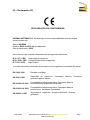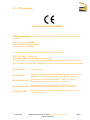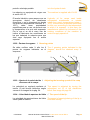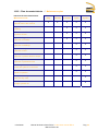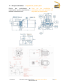
1
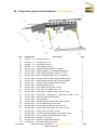
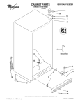
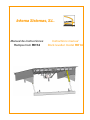
Inkema Sistemas, S.L.
Manual de instrucciones
Rampa mod. RH14
Instructions manual
Dock leveller model RH14
Índice / Index
Contenido / Contents
Pág.
01 – Índice / Index
1
02 – Introducción / Introduction
2
03 – Declaración CE / CE Declaration
4/5
04 – Conjuntos y piezas de la maquina / List of parts
6
05 – Transporte / Transport
8
06 – Montaje / Assembly
9
07 – Desinstalación / Disassembly
13
08 – Instrucciones de uso / Instructions of use
15
09 – Ficha técnica / Technical specifications
18
10 – Mantenimiento / Maintenance
21
11 – Grupo hidráulico / Hydraulic power pack
24
12 – Conexión eléctrica / Electrical connection
25
13 – Condiciones y limites de uso / Conditions and limits for use
26
14 – Contacto / Contact
27
07/01/2008
Manual de instrucciones RH14 / Instructions manual RH14
Manual RH14.doc
Pág. 1
02 – Introducción / Introduction.
Este manual es una guía, para el uso y This manual is a guide, for the correct
mantenimiento correcto y seguro de la and safe use and maintenance of the
dock leveller RH14.
rampa RH14.
El cumplimiento de las instrucciones de
su contenido asegura una larga duración
de la máquina y el respeto de las normas
de seguridad evita los accidentes más
comunes que pueden ocurrir durante el
trabajo o el mantenimiento.
Following these instructions will ensure a
long life span of the machine, and the
most common accidents that could occur
during operation or maintenance will be
prevented by adhering to the safety
regulations.
Las instrucciones contenidas en este
manual, no pueden por si mismas hacer
seguro el trabajo y no eximen al
operador a observar el código de
seguridad o ley, regla o reglamento local
o nacional.
The instructions included in this manual
cannot ensure full labour safety and do
not exempt the operator from observing
local or national safety codes, laws or
regulations.
La norma de servicio representada en The service standard represented in this
este manual vale exclusivamente para manual is only for mobile ramps used for
las rampas móviles, para trabajos de loading and unloading trucks.
carga y descarga de camiones.
En caso de extravío del manual de
instrucciones y mantenimiento, se debe
solicitar otra copia del mismo, el cual es
específico para la máquina. Es
completamente necesario y obligatorio
que el manual esté siempre con la
máquina para poder consultar en
cualquier momento o si existiera una
duda en la utilización de la misma.
If these instructions and maintenance
manual is lost, another copy should be
requested, specifically for this machine.
It is essential and compulsory that this
manual
always
accompanies
the
machine so that it can be easily
consulted at any time and whenever
there is any doubt regarding the use of
the machine.
El fabricante no tiene control directo
sobre las operaciones, ubicaciones o
manutención de la máquina. Es
responsabilidad del operario hacer una
buena
práctica
de
seguridad
y
mantenimiento.
The manufacturer does not have direct
control over the operations, location or
maintenance of the machine.
The
operator is responsible for safe working
and maintenance practice.
Es responsabilidad del operario leer y The operator is responsible for reading
entender el presente manual antes de and understanding this manual before
using the machine.
utilizar la máquina
El utilizar la máquina con cautela y con
una formación adecuada no sólo protege
al operario, sino a las personas que
dependen de su trabajo.
If the operator is properly trained and
uses the machine with care, he will not
only protect himself but also all the
people involved in his work.
La información contenida en el manual The information contained in this manual
is valid at the time of publication.
es válida en la época de su publicación.
07/01/2008
Manual de instrucciones RH14 / Instructions manual RH14
Manual RH14.doc
Pág. 2
Las fotografías y los dibujos son
genéricos y por lo tanto, esta información
puede sufrir alguna variación debido al
constante desarrollo e investigación por
parte de INKEMA SISTEMAS S.L.
Photographs and drawings are generic
and therefore this information may vary
as a result of the constant research and
development conducted by INKEMA
SISTEMAS S.L.
Consulte al departamento técnico si se Consult the technical department if you
are in any doubt.
encuentra en discrepancia.
El manual es parte integrante de la The manual forms part of the machine
máquina y debe ser adjuntado a la and should be attached to it if the
machine is sold.
misma en caso de venta.
07/01/2008
Manual de instrucciones RH14 / Instructions manual RH14
Manual RH14.doc
Pág. 3
03 – Declaración CE
DECLARACION DE CONFORMIDAD
INKEMA SISTEMAS S.L. declara bajo su única responsabilidad que las rampas
electro-hidráulicas:
Marca: INKEMA
Modelo: RH14 de 6000 Kg de capacidad
Año de fabricación: 2008
Es conforme a los requisitos esenciales de las siguientes directivas:
D 98 / 37 / CEE
D 89 / 336 / CEE
D 73 /23 / CEE
Seguridad de maquinas.
Compatibilidad electromagnética.
Baja tensión.
Y ha sido calculada y diseñada de acuerdo con las siguientes normativas Europeas:
EN 1398:1998
Rampas nivelables
EN 292-2:1991
Seguridad de máquinas.
generales para el diseño.
EN 61000-6-2:2001
Compatibilidad electromagnética. Conceptos básicos
inmunidad para ambientes industriales.
EN 61000-6-4:2001
Compatibilidad electromagnética. Conceptos básicos
emisiones en ambientes industriales.
EN 60204-1:1997
Seguridad de máquinas – Equipos eléctricos – Normas
generales.
07/01/2008
Conceptos
básicos.
Manual de instrucciones RH14 / Instructions manual RH14
Manual RH14.doc
Principios
Pág. 4
03 – CE Declaration
DECLARATION OF CONFORMITY
INKEMA SISTEMAS S.L. declares under its own responsibility that its product Dock
Leveller:
Brand name type: INKEMA
Models: RH14 of capacity 6000 Kg
Year serial number: 2008
It’s in agreement to the essential requirements or the guidelines:
D 98 / 37 / CEE
D 89 / 336 / CEE
D 73 /23 / CEE
Machinery.
Electromagnetic Compatibility.
Electrical Equipment designed for use within certain voltage limits.
And has been calculated and designed according to the following European standards:
EN 1398:1998
Dock Levellers
EN 292-2:1991
Safety of machinery - Basic concepts, general principles for
design - Part 2 : Technical principles and specifications
EN 61000-6-2:2001
Electromagnetic compatibility (EMC) -- Part 6-2: Generic
standards Immunity for industrial environments
EN 61000-6-4:2001
Electromagnetic compatibility (EMC) -- Part 6-4: Generic
standards Emission standard for industrial environments
EN 60204-1:1997
Safety of machinery - Electrical equipment of machines - Part
1: General Rules
07/01/2008
Manual de instrucciones RH14 / Instructions manual RH14
Manual RH14.doc
Pág. 5
04 – Conjuntos y piezas de la máquina / List of parts
Pos.
10
21
22
30
40
40
40
40
40
40
40
45
45
45
45
45
45
45
45
45
50
60
71
71
71
72
72
73
07/01/2008
Código pieza
Descripción
20.0001 … (*) Estructura p/RH (*)
20.0002 … (*) Conj.banc.RH14 (*)
20.0022 … (*) Frontal banc.RH14 (*)
20.0003 … (*) Labio abatible 6t RH (*)
20.0017.0001 Centralita hidráulica p/RH (Completa)
30.0011.0008 Depósito plástico 7 Lit. p/centralita hidraulica
30.0011.0007 Cuerpo bomba hidraulica p/RH1 de 1.8cc/v
30.0015.0005 Motor centralita 400/230v 3F 1.1cv 3000rpm
30.0011.0009 Corredera electroválvula seg.p/centralita p/RH1
30.0011.0010 Bobina p/electroválvula seg. p/centralita p/RH1
30.0011.0011 Conector eléctrico bobina electroválvulas
30.0011.0001 Arandela metalbuna 3/8"
30.0011.0002 Racor M/M rosca 3/8" Gas cincado
30.0011.0014 Racor reducción M/M de 3/8" a 1/4"
30.0011.0003 Flexible hidr. 2 salidas rectas 3/8" Gas L=700
30.0011.0004 Flexible hidr. 1 salida recta + 1 salida 90º 1/4" Gas L=1700
30.0011.0005 Grasa tipo Renolit sólida (50kg)
30.0011.0006 Aceite hidráulico
30.0012.0009 Arandela seg.Grower M10 DIN-7980 Cincada
30.0012.0010 Tornillo M10x20 DIN-933 cincado
30.0010.0006 Cilindro hidraulico Ø35 e/c=693 carr=538
30.0010.0002 Cilindro simple efecto Ø30 e/c =260 carr=105
30.0008.0007 Faldón móvil 1250x365x1.5 Galv.
30.0012.0002 Tornillo alomado allen M6x16 ISO-7380 Cincado
30.0012.0003 Tuerca autoblocante M6 DIN-985 Cincado
30.0006.0008 Eje Ø16 x 70 cincado
30.0012.0039 Pasador de aletas Ø5x28 DIN-94
30.0006.0011 Eje p/cilidro Ø25x120 cincado
Manual de instrucciones RH14 / Instructions manual RH14
Manual RH14.doc
Cant
1
1
1
1
1
1
1
1
1
1
1
3
3
3
2
1
0.2
7
2
2
2
1
1+1
2
2
2
4
2
Pág. 6
73
74
75
75
76
76
77
77
77
77
77
30.0012.0040
30.0006.0059
30.0006 … (*)
30.0012.0040
30.0006.0007
30.0012.0034
20.0018.0001
30.0015.0001
30.0015.0002
30.0015.0003
30.0015.0004
Pasador de aletas Ø5x40 DIN-94
Eje p/coliso Ø30x103 cincado
Eje uña Ø22 (*)
Pasador de aletas Ø5x40 DIN-94
Eje bisagras traseras Ø19 x 175 cincado
Anilla seeger DIN-471 para eje de Ø19 / Ø17.5
Cuadro eléctrico p/RH1 (standar)
Manguera electric 4x1.5 Negro/ Marron/Gris clase 5 ó 6
Cable electrico negro 2x1 Aceflex AG
Tubo BGR M25 PG-9 c/dos manguitos.
Terminal cableado VA105
4
2
2
4
3
6
1
10
10
1.5
4
(*) Especificar el código de la pieza y descripción, así como el modelo y dimensión de la máquina.
Pos.
10
21
22
30
40
40
40
40
40
40
40
45
45
45
45
45
45
45
45
50
60
71
71
71
72
72
73
73
74
75
75
76
76
77
77
77
77
Machine code
20.0001 … (*)
20.0002 … (*)
20.0022 … (*)
20.0003 … (*)
20.0017.0001
30.0015.0005
30.0011.0007
30.0011.0008
30.0011.0009
30.0011.0010
30.0011.0011
30.0011.0001
30.0011.0002
30.0011.0014
30.0011.0003
30.0011.0004
30.0011.0006
30.0012.0009
30.0012.0010
30.0010.0001
30.0010.0002
30.0008.0007
30.0012.0002
30.0012.0003
30.0006.0008
30.0012.0039
30.0006.0011
30.0012.0040
30.0006.0059
30.0006 … (*)
30.0012.0040
30.0006.0007
30.0012.0034
20.0018.0001
30.0015.0001
30.0015.0002
30.0015.0003
Description
Mobile structure 6t RH (*)
Set base structure RH14 (*)
Frontal base structure RH14 (*)
Folding lip 6t RH1 (*)
Powerpack RH (assembly)
Electric engine 400/230v 3F 1.1cv 3000rpm
Hydraulic pump 1.7cc/v
Hydraulic tank 7 Lit.
Safety valve RH1
Electric coil
Electric connector
Washer for hydraulic oil 3/8"
Hydraulic connector M/M 3/8" Gas
Hydraulic reduction M/M 3/8" 1/4"
Hydraulic hose 3/8" Gas L=700
Hydraulic hose 1/4" Gas L=1700
Hydraulic oil
Washer M10 DIN-7980
Screw M10x20 DIN-933
Rod cylinder Ø50 e/c=625 x 470
Rod cylinder Ø30 e/c =260 x 105
Mobile flap 1200x365x1.5 Galv.
Screw M6x16 ISO-7380 Zincing
Nut M6 DIN-985
Axis Ø16 x 70
Pin Ø5x28 DIN-94
Axis Ø25x120 zincing
Pin Ø5x40 DIN-94
Axis Ø30 x 103
Axis Ø22 (*)
Pin Ø5x40 DIN-94
Axis Ø19 x 175
Washer seager DIN-471 Ø19 / Ø17.5
Control box RH1 (standar)
Electric cable 4x1.5
Electric cable 2x1
Pipe BGR M25 PG-9
Cant
1
1
1
1
1
1
1
1
1
1
1
2
2
2
1
1
7
2
2
1
1
1+1
2
2
2
4
1
2
1
2
4
3
6
1
10
10
1.5
(*) It is necessary to specify the code of the piece and description, as well as the model and the
dimensions of the machine.
07/01/2008
Manual de instrucciones RH14 / Instructions manual RH14
Manual RH14.doc
Pág. 7
05 – Transporte / Transport
En el transporte la maquina va
completamente plegada. Para
aprovechar el espacio del transporte al
máximo. (Ver dimensiones en el Pto.
09.07 de la Pag.20).
07/01/2008
During transport the leveller is completely
folded to make the best use of the
existing transport space (see dimensions
under point 09.07 on page 20)
Manual de instrucciones RH14 / Instructions manual RH14
Manual RH14.doc
Pág. 8
06 – Montaje / Assembly instructions.
06.01 – Colocación en el foso / Positioning in the pit
MUY IMPORTANTE: En la manipulación
de la rampa se ha de respetar en todo
momento la ley de prevención de riesgos
laborales, así como los reglamentos de
seguridad, salud e higiene en el trabajo.
VERY IMPORTANT: When handling the
ramp, the work risk prevention law and all
safety, health and hygiene regulations at
work, must be followed.
La colocación de la rampa en el foso
debe efectuarse con la ayuda de una
grúa o similar y para izarla utilizaremos
cadenas, eslingas o similar. Con una
capacidad de carga igual o superior al
peso de la rampa. (ver tabla de
dimensiones y pesos en la ficha técnica
Pág. 20)
The ramp should be positioned in the pit
with a crane or similar and raised using
chains, slings or similar, with a load
capacity equal or higher than the weight
of the ramp. (See weight table in the
technical specifications on page 20).
Para la colocación se le atornillará las To place the leveller, its anchoring pieces
piezas de anclaje para poder sujetar la have to be screwed down, so the leveller
could be fixed and rest in the pit.
rampa y apoyarla en el foso.
En ese momento, desenrollar el cable
eléctrico y pasarlo por el tubo que hay
centrado en la parte posterior del foso.
Una vez el cable haya salido por
completo por el otro extremo del tubo,
proceder a colocar correctamente la
rampa en el foso.
Unwind the electrical cable and pass it
through the pipe that is centred in the
bottom part of the pit. Once the cable
completely emerges from the other end
of the pipe, place the ramp correctly in
the pit.
Posteriormente, se centrara y se
colocara el conjunto abisagrado trasero
de la maquina apoyando el mismo en el
perfil “L” invertido que existe en la parte
posterior del foso.
Afterwards the hinged part at the back of
the leveller has to be centered and
placed on the inverted “L”profile in the
back part of the Pit.
Soldar la parte trasera de la maquina al
foso, con 5 cordones de soldadura de
6mm de garganta y 100mm de longitud
repartidos y separados 375mm.
Las zonas de soldadura están indicadas
en el siguiente esquema.
Weld the back part of the leveller to the
Pit, with 5 welding lines of a throat of
6mm and 100mm length each, distributed
and separated by 375 mm.
The welding zones are shown on the
following drawing.
07/01/2008
Manual de instrucciones RH14 / Instructions manual RH14
Manual RH14.doc
Pág. 9
Piezas de anclaje
Destornillar el soporte delantero, del Unscrew the front support of the front part
frontal, para colocarla en la bancada, (ver to place it into the frame (see previous
drawing)
la figura anterior).
Estirar el frontal con los cilindros hasta
colocarlo en su posición correcta, de
forma que cuando el labio descanse
sobre sus apoyos, la máquina quede
totalmente horizontal y el frontal no salga
del foso. Normalmente ha de quedar un
margen entre el frontal y el foso de 10mm
a 30mm. (Ver los siguientes esquemas).
07/01/2008
Stretch the frontal with the cylinders, until
placing it into its right position, the way
the leveller is completely horizontal, when
the lip is resting on its supports and the
frontal does not overpass the Pit.
Normally a margin of 10 to 30 mm should
be left between the frontal and the Pit
(see following drawings)
Manual de instrucciones RH14 / Instructions manual RH14
Manual RH14.doc
Pág. 10
Soldar la parte delantera de
la bancada, con 2 cordones
de 6mm de garganta y
longitud centrados respecto
frontales de la uña.
la maquina a
de soldadura
200mm de
a los apoyos
Weld the front part of the leveller to the
frame, with 2 welding cords with a throat
of 6 mm and 200 mm length, centered
regarding to the frontal supports of the lip.
Una vez realizadas todas las soldaduras Once all weldings are made, the back,
anchoring parts could be withdrawn.
retirar las piezas de anclaje traseras.
06.02 – Conexionado de la rampa / Connecting the dock leveller
La ubicación del cuadro eléctrico en la The location of the control box in the wall
pared debe de coincidir con el lado del must be on the same side than the truck
conductor
del
vehiculo
a driver. (see the next drawing)
cargar/descargar, (ver el siguiente
esquema)
Secure the electric control panel box to
Fijar la caja del cuadro eléctrico a la the wall, at the required height and
pared, a la altura deseada y aligned with the outlet of the ramp
perfectamente alineado con la salida de cables.
los cables de la rampa.
Cut the plastic pipe to pass the cables
Ajustar el tubo para el paso de los cables through it. It must be the same length as
eléctricos a la distancia que hay entre el the distance from the electric control
panel to the floor of the loading bay.
cuadro eléctrico y el suelo.
Fijar el tubo a la pared (como mínimo
con 3 abrazaderas), debe quedar
perpendicular al suelo del muelle de
carga y alineado con la salida de los
cables de la rampa.
Secure the pipe to the wall (with at least
3 clamps). It should be perpendicular to
the floor of the loading bay and aligned
with the outlet of the ramp cables.
El tubo de plástico se entrega precintado The plastic pipe is supplied attached to
a uno de los laterales de la bancada de one of the sides of the ramp base.
la rampa.
07/01/2008
Manual de instrucciones RH14 / Instructions manual RH14
Manual RH14.doc
Pág. 11
Cuadro eléctrico rampa
Dock leveller control box
Conduccion eléctrica vista
Electric pipe on the wall
Conduccion eléctrica bajo tierra
Electric pipe under ground
Una vez esté todo bien fijado, pasar
los cables y conectar según esquema
eléctrico adjunto que encontraremos
en el interior del cuadro eléctrico.
Once this has all been well secured,
pass the cables through the pipe and
connect them following the attached
electrical diagram inside the control
box.
MUY IMPORTANTE: Soltar los
faldones laterales, rompiendo el VERY IMPORTANT: Release the
remache que los sujeta y comprobar lateral Toe guards by breaking the
fastener, and test its movement and
su movimiento y funcionalidad.
functionality.
Finalmente revisar el buen estado de
la pintura de la rampa, repasando los Finally check the condition of the paint
defectos de la misma y soldaduras work of the ramp and touch up any
que
recientemente
se
hayan defects or recent welds.
realizado.
La instalación se puede dar por
finalizada
cuando
el
instalador
autorizado por INKEMA SISTEMAS,
S.L. cumplimente la correspondiente
ficha de control de montaje.
07/01/2008
The installation is ready once the fitter,
authorised by INKEMA SISTEMAS
S.L., has filled in the corresponding
assembly control sheet.
Manual de instrucciones RH14 / Instructions manual RH14
Manual RH14.doc
Pág. 12
07 – Desinstalación / Disassembly
MUY IMPORTANTE: La manipulación de
la rampa se debe respetar en todo
momento la ley de prevención de riesgos
laborales, así como los reglamentos de
seguridad, salud e higiene en el trabajo.
VERY IMPORTANT: When handling the
ramp, the work risk prevention law and all
safety, health and hygiene regulations at
work, must be followed.
Seguir los siguientes pasos:
Follow the next steps:
Estando la rampa en posición de reposo,
debemos de cortar completamente el
suministro eléctrico previo al cuadro
eléctrico, con el fin de poder desconectar
completamente el cuadro y dejar todos
los
cables
eléctricos
sueltos
y
preparados para ser retirados.
With the leveller in its resting position,
you have to switch off completely the
energy supply previous to the control
panel, to be able to disconnect it and
leave free all electrical cables, so they
can be withdrawn.
Seguidamente instalaremos las piezas
de anclaje.
Debemos de enganchar la rampa en
dichas piezas de anclaje. Para ello
usaremos unas cadenas, eslingas o
similar (que tengan una capacidad de
carga igual o superior al peso de la
rampa)
Following the back, anchoring parts have
to be installed.
The leveller has to be fixed to the
mentioned anchoring pieces. You will
have to use chains, slings or similar
which should have an equal or higher
loading capacity than the weight of the
ramp.
Esta operación debe efectuarse con la
ayuda de una grúa o similar, que tenga
una capacidad de carga igual o superior
al peso de la rampa. (Ver cuadrante en
ficha técnica, pág. 20).
This operation has to be made with the
help of a crane or similar which should
have an equal or higher loading capacity
than the weight of the ramp.
(see list of technical sheet, page 20)
07/01/2008
Manual de instrucciones RH14 / Instructions manual RH14
Manual RH14.doc
Pág. 13
Acto seguido cortaremos todas las
soldaduras que unen la rampa al foso,
tras lo cual podemos elevar la misma y
manipular el frontal de esta para fijarlo
bajo el labio mediante los tornillos M10,
quedando la máquina en su posición de
transporte.
Cut all the welds that secure the ramp to
the pre-frame. Now you can raise the
leveller and fix the frontal under the lip
with screws M10, so the leveller achieves
its transport position.
Liberar los cables eléctricos de su
conducto, sacar por completo la rampa
del foso y disponer de la misma para su
transporte.
Release the electrical cables of the pipe,
remove the leveller completely from the
Pit and place it the way, it is possible to
transport it.
El cuadro eléctrico, se puede desmontar You can dismantle the control box por
por completo o bien dejar el mismo in completely or leave it in its place for
situ para la futura conexión de otra future uses.
rampa.
07/01/2008
Manual de instrucciones RH14 / Instructions manual RH14
Manual RH14.doc
Pág. 14
08 – Instrucciones de uso / Instructions of use
08.01 – Antes del uso / Before use
Comprobar visualmente que la rampa Visually check that the ramp is in perfect
conditions of use.
está en perfectas condiciones de uso.
Centrar el vehículo contra los topes de Centre the vehicle against the rubber
bumpers of the ramp.
goma de la rampa.
Comprobar que el
vehículo está Ensure that the vehicle is totally immobile
perfectamente inmovilizado y bloqueado. and locked. (Turn off the engine, put on
(Parar el motor, poner el freno de mano y the handbrake and wedge the wheels).
calzar las ruedas).
Para elevar la rampa hasta el nivel de la To lift the ramp up to the level of the load
surface:
superficie de carga :
Conectar el circuito de maniobra girando Connect the operation circuit by turning
el interruptor superior de color Rojo. En the upper Red switch. The green pilot will
este momento se encenderá el piloto de then light up.
color verde.
Para elevar la rampa y abrir el labio, To lift the ramp and open the lip, keep
presionar de forma continúa el pulsador. the button pressed.
Si dejara de presionar el pulsador de
elevación, la rampa bajaría por su propio If the elevation button is released, the
ramp will lower by its own weight, at a
peso a una velocidad graduada.
gradual speed.
Elevar la rampa hasta que empiece a
abrirse el labio. Una vez abierto todo el Lift the ramp until the lip starts to open.
Once the lip is fully open, release the
labio, soltar el pulsador.
button.
Dejar
que
la
rampa
descienda
gradualmente y se apoye sobre la Let the ramp lower gradually until it rests
on the truck loading surface.
superficie de carga del camión.
07/01/2008
Manual de instrucciones RH14 / Instructions manual RH14
Manual RH14.doc
Pág. 15
Comprobar que la uña, queda finalmente Ensure that the lip finally rests on the
apoyada, sobre la superficie de carga del vehicle loading surface in a space not
vehículo en un espacio no inferior a less than 100 mm.
100mm.
08.02 – Durante el uso / During use
La rampa quedará simplemente apoyada
sobre la superficie de carga (camión).
Los cilindros hidráulicos no estarán
bloqueados para permitir la adaptación
de la rampa a la altura de la superficie
de carga (que variará según varíe la
suspensión del camión).
The ramp will simply remain resting on
the load surface (truck). The hydraulic
cylinders will not be locked to enable the
ramp to be adjusted to the height of the
load surface (that will vary according to
the suspension of the truck).
Asegúrese que el paro de emergencia Ensure that the emergency stop button is
NOT ON.
no está activado.
Queda
terminantemente
prohibido It is forbidden to load or unload when the
realizar operaciones de carga y emergency stop is on.
descarga con el paro de emergencia
activado.
No sobrepasar bajo ningún concepto la Never exceed the maximum nominal
carga máxima nominal. (Ver placa de load. (See specifications plaque).
características de la misma).
Vigilar que durante el tránsito de carga
que no se pierda el apoyo de la rampa
sobre la superficie de carga. En caso de
que esto ocurra, gire el seccionador
general a la posición (0) para que actúe
como paro de emergencia.
Ensure that the ramp is always resting on
the load surface during load transit.
Immediately twist the main switch to (0)
position for activate stop emergency
Las carretillas deben circular con
precaución. La velocidad máxima de
tránsito para la que ha sido calculada la
rampa es de 10Km/hora.
Fork-lift trucks should be driven with care.
The maximum transit speed on these
ramps has been calculated at 10
km/hour.
08.03 – Después del uso. / After use.
Elevar la rampa y cerrar el labio antes de
que el camión abandone su posición de
carga. Para ello presionar el pulsador,
elevando la rampa el espacio suficiente
para salvar el camión.
Lift the ramp and close the lip before the
truck leaves the loading position. To do
this, press the button, lifting the ramp
sufficiently to avoid the truck once the
platform is at its fullest height.
Soltar el pulsador y esperar a que la Release the button and wait until the
rampa descienda a una velocidad ramp descends at a controlled speed,
regulada y se apoye con el labio cerrado and rests on the base with the lip closed.
sobre la bancada.
07/01/2008
Manual de instrucciones RH14 / Instructions manual RH14
Manual RH14.doc
Pág. 16
08.04 – Precauciones de uso. / Precautions of use.
Asegúrese que el paro de emergencia Ensure that the emergency stop system
no está activado, o sea, que el is off, or main switch on (I) position.
seccionador esté en la posición (I).
Never exceed the maximum nominal
No sobrepasar bajo ningún concepto la load. (See specifications plaque).
carga máxima nominal. (Ver placa de
características de la misma).
Antes de cada maniobra verificar que no Before each operation, check that there is
nobody in the work area.
hay personas en el área de trabajo.
Comprobar que la rampa queda bien Ensure that the ramp rests properly on
apoyada sobre la superficie de carga del the load surface of the truck, connecting
camión, acoplando toda la uña en una the whole lip on a 100 mm long surface.
superficie de 100 mm de largo.
El grupo hidráulico tiene como única The sole purpose of the hydraulic unit is
función levantar la rampa para situarla to lift the ramp to place it on the load
sobre la superficie de carga. Nunca se surface. It can never be used to lift loads.
puede utilizar para levantar carga.
Antes de elevar la rampa asegúrese que Before lifting the ramp, ensure that it
su movimiento no se ve obstaculizado cannot be blocked by other equipment
(doors, etc...).
con otros equipos. (Puertas, etc... )
Al final de la operación comprobar que la At the end of the operation, check that the
lip is properly fitted into its rest position.
uña este bien encajada.
07/01/2008
Manual de instrucciones RH14 / Instructions manual RH14
Manual RH14.doc
Pág. 17
09 – Ficha técnica / Technical specifications
Rampa esta diseñada
normativa UNE-EN 1398
cumpliendo The ramp is designed in accordance with
the standard UNE-EN 1398
Calculada para una carga máxima It is calculated for a maximum nominal
nominal de: (Ver placa de características load of: (See specifications plaque of the
de la rampa).
ramp).
Está compuesta por tres
Plataforma, labio y bancada.
partes: It is composed of three parts: Platform,
lip and base.
Los movimientos de la plataforma y el The platform and lip are moved by means
labio, se realizan mediante un grupo of an electro-hydraulic unit.
electro-hidráulico.
09.01 - Plataforma: / Platform:
- Chapa superior lagrimada (Grueso
5/7mm.), calidad ST-37.
- 10 Perfiles tipo IPN.
- 2 Perfiles laterales laminados en frío
(faldones de seguridad anticizalla.
- Conjunto frontal de bisagras
(articulación labio).
- Conjunto trasero de bisagras
(articulación plataforma).
- Barra de seguridad para realizar
trabajos de mantenimiento.
- Top tearplate (5/7mm. thick), quality
ST-37.
- 10 Profile type IPN
- 2 cold-rolled reinforcement sections
(anti-shearing safety toe guards).
- Front hinge unit (lip articulation).
- Rear hinge unit (platform articulation).
- Safety bar for maintenance work.
09.02 - Labio: / Lip:
- Chapa lagrimada (Grueso 13/15mm.),
calidad ST-37.
- Plegado de 5º a 150mm. del extremo
(para el perfecto ajuste al camión).
- Fresado en el extremo (para suavizar
el paso de las carretillas).
- Tearplate (Thickness 13/15 mm),
quality ST-37.
- 5º press stroke at 150 mm from end (to
perfectly adjust to the truck).
- Milled at the end (to level the way for
fork-lift trucks)
09.03 - Bancada: / Base
- Conjunto trasero (cabezal) compuesto
por perfiles laminados.
- Conjunto frontal con perfiles para
apoyo labio.
- Rear unit (header) composed of
laminated sections.
- Front unit with sections to support the
lip.
09.04- Centralita hidráulica: / Powerpack:
- Motor eléctrico de 1.5CV. 380V. 50Hz. - 1.5 HP, 380 V. 50 Hz. electric motor.
pump
with
flow
of
- Bomba hidráulica con caudal 5 - Hydraulic
5 litres/minute.
litros/minuto.
- Depósito de 7 litros con visor de nivel - 7 litre tank with oil level indicator.
07/01/2008
Manual de instrucciones RH14 / Instructions manual RH14
Manual RH14.doc
Pág. 18
de aceite.
- Bloque donde se incorporan todos los
elementos (incluida electroválvula con
maniobra a 24V).
- 2 cilindros de Ø35mm. de vástago para
elevación de plataforma, con válvula
de seguridad paracaídas.
- 1 cilindro de Ø30mm. de vástago para
elevación del labio.
- Latiguillos
- Unit
incorporating
all
elements
(including 24V electro-valve).
- 2 rod cylinders of Ø35mm. to lift the
platform, with safety drop valve.
- 1 rod cylinder of Ø30mm. to lift the lip.
- Hoses.
09.05 – Cuadro eléctrico: / Electric control panel:
- Transformador
para
circuito
de - Transformer for 24V circuit.
- Green start-up light.
maniobra a 24v.
- Drive control.
- Luz verde de puesta en marcha.
- Main switch/emergency stop.
- Mando de accionamiento.
- Thermal.
- Seccionador/paro de emergencia.
- Fuses.
- Térmico.
- Connection strip.
- Fusibles.
- Box 240x190x95(IP-55 protection)
- Regleta de conexiones.
- Caja 240x190x95 (protección IP-55)
09.06 – Sistemas de seguridad: / Safety systems:
- Seccionador/paro de emergencia
- Válvula de seguridad en cilindro
elevación
- Faldones laterales
- Superficie antideslizante
07/01/2008
-
Main switch/emergency stop
Safety valve in each elevation cylinder
Side skirts
Non-slip surface
Manual de instrucciones RH14 / Instructions manual RH14
Manual RH14.doc
Pág. 19
09.07 – Dimensiones maquina. / Machine dimensions.
Dimensiones en mm. / Dimensions in mm.
Peso en Kg. / Weight in Kg
07/01/2008
Manual de instrucciones RH14 / Instructions manual RH14
Manual RH14.doc
Pág. 20
10 – Mantenimiento / Maintenance
El correcto funcionamiento y la larga The good working order and long life
duración de la rampa depende en gran span of the ramp depends largely on the
parte del mantenimiento preventivo que preventive, performed maintenance.
se efectúe.
El mantenimiento avanzado únicamente
lo puede realizar el Servicio Técnico de
INKEMA SISTEMAS S.L. o personal
homologado por la misma.
Our product’s maintenance can be
carried out only by INKEMA SISTEMAS
S.L. technical department or official
authorised technicians.
Este mantenimiento se realiza con el fin
de que el producto conserve las
características de seguridad y uso que
posee en el momento de la instalación.
This maintenance is carried out in order
to preserve each security feature as well
as its correct operability provided at the
moment of its installation.
Cualquier
cambio,
reparación
o
manipulación del producto que no
cumpla con estas directrices, conllevará
la anulación del periodo de garantía de
dos años y la responsabilidad de
INKEMA SISTEMAS S.L. sobre el
producto será anulada automáticamente.
Any change, repair or manipulation of the
product which do not follow above
directive, will imply the cancellation of
INKEMA SISTEMAS S.L. 2 years
product warranty, our product liability and
homologation.
El engrase, pintura y vigilancia Greasing, painting and ongoing care are
continuada son la mejor garantía de the best guarantee for many years of
buenas prestaciones durante muchos trouble-free operation.
años.
10.01 - Aceite hidráulico / Hydraulic oil
El aceite hidráulico se debe reemplazar Hydraulic oil should be changed every
two years.
una vez cada dos años.
El aceite debe contener agentes que
impidan la formación de espuma, la
oxidación y la absorción de agua. Si las
temperaturas invernales son muy bajas,
el aceite debe ser poco denso y con un
índice de viscosidad estable a bajas
temperaturas.
The oil should contain agents that prevent
the formation of foam, rust and water
absorption. If winter temperatures are
very low, the oil should not be very dense
and with a stable viscosity index at low
temperatures.
No se debe mezclar nunca distintos
aceites pues el aceite nuevo puede tener
una resistencia a la oxidación distinta e
influir en la duración del aceite original.
Different oils should never be mixed, as
new oil may have a different degree of
rust resistance and affect the duration of
the original oil.
Es importante verificar el nivel de aceite
cada 6 meses. El depósito de aceite se
debe rellenar hasta que el mismo se
rebose por el tapón de cierre en la
The oil level must be checked every 6
months. The oil tank should be topped
until it flows out of the sealing cap in the
lowest possible position, as then oil only
07/01/2008
Manual de instrucciones RH14 / Instructions manual RH14
Manual RH14.doc
Pág. 21
posición más baja posible.
is in the hydraulic tank.
La máquina va equipada de origen con The machine is supplied with HVI-32.
el aceite HVI-32
El aceite hidráulico para rampas que se
encuentren
dentro
de
almacenes
frigoríficos, o en la intemperie en donde
se alcancen temperaturas inferiores a (10ºC),
debe
tener
propiedades
específicas para su uso, de acuerdo con
la temperatura a la que esté expuesta.
Por lo que si se da el caso, han de
indicar al fabricante las condiciones en
las que trabajará la máquina para que
ésta vaya equipada con el aceite
especial.
Hydraulic oil for ramps used inside
refrigerated warehouses, or outside
where they reach temperatures below (10ºC), should have properties specifically
for this use, according to the temperature
to which it is exposed. In this case, the
manufacturer should be informed of the
working conditions of the machine in
order to supply special oil.
10.02 - Puntos de engrase. / Greasing points
Se debe verificar cada ½ año los 6 The 6 greasing points indicated in the
puntos de engrase indicados en el diagram, should be checked every ½
esquema.
year.
1
3
4
5
6
2
10.03 – Ajuste de la velocidad de / Adjusting the lowering speed of the ramp
descenso de la rampa
La velocidad se regulará mediante el This speed is adjusted by turning the
tornillo (2) del bloque hidráulico según adjustment nut (2) of the distribution
vemos en la imagen de la pág. 24.
block. See image on page 24.
10.04 – Velocidad de apertura del labio / The speed of the lip.
La velocidad de apertura/cierre del labio The speed of opening/closing of the lip is
viene fijada de fábrica.
fixed from factory
07/01/2008
Manual de instrucciones RH14 / Instructions manual RH14
Manual RH14.doc
Pág. 22
10.05 – Plan de mantenimiento / Maintenance plan
Intervención de mantenimiento
Diario
Cada mes
6 meses
1 año
2 años
Maintenance task
daily
monthly
6 months
1 year
2 years
♦
♦
♦
♦
♦
♦
♦
♦
♦
♦
♦
♦
♦
♦
♦
♦
♦
♦
♦
♦
♦
♦
♦
♦
♦
♦
Estado general de la máquina
General state of the machine
Engrase
Greasing
Nivel de aceite hidráulico
Hydraulic oil level
Inspección fugas de aceite
Inspection of oil leaks
Inspección de soldaduras
Inspection of weldings
Inspección de ejes
Inspection of axis
Inspección bandas adhesivas laterales
Inspection of plastic adhesive stripes
Inspección pintura
Inspection of painted surface
Flexibles y rácores
Hoses and hydraulic connections
Velocidad de maniobra
Speed of operation
Comprobar válvula paracaídas
Verify security valve
Cambio de aceite hidráulico
Change hydraulic oil
07/01/2008
Manual de instrucciones RH14 / Instructions manual RH14
Manual RH14.doc
♦
♦
Pág. 23
11 – Grupo hidráulico / Hydraulic power pack
Existen
dos
posibilidades
de There are two possibilities of
motorización, que son equivalentes y motorization, they are equivalent and
realizan la misma función.
they make the same function
07/01/2008
Manual de instrucciones RH14 / Instructions manual RH14
Manual RH14.doc
Pág. 24
12 – Conexión eléctrica. / Electrical connection.
Ver el esquema eléctrico que se Look at the electrical wiring diagram
encuentra en el interior del cuadro inside the control box.
eléctrico.
07/01/2008
Manual de instrucciones RH14 / Instructions manual RH14
Manual RH14.doc
Pág. 25
13 – Condiciones y limites de uso / Conditions and limits
for use
- Capacidad nominal de carga 6t
- Capacity of load 6t
- Tensión eléctrica 230/400 volt. 50Hz
- Electrical power 230/400 volt. 50Hz
- Potencia motor eléctrico 1.1 Kw.
- Electric engine 1.1 Kw.
- Presión máx. de trabajo del circuito
hidráulico 140 kg/cm² (Bar)
- Pressure max. of work of hydraulic
systems 140 kg/cm ² (Bar)
- Rango temperatura de trabajo
(-10ºC +40ºC)
- Range of temperature
(-10ºC +40ºC )
- Nivel de ruido producido <70db
- Noise level <70db
- Velocidad máx. transito 10Km/h
- Speed max. for transit 10Km/h
- Pendiente máx. de trabajo 10% (7º)
- Slope max. of work 10% (7º)
- No trabajar con la máquina mientras la
parada de emergencia se encuentre
activada, o sea mientras el
seccionador esté en posición (0).
- Don't work with the dock leveller while
the emerging stop is ON or main swicht
on (0) position.
07/01/2008
Manual de instrucciones RH14 / Instructions manual RH14
Manual RH14.doc
Pág. 26
14 – Contacto / Contact
Inkema Sistemas, S.L.
Fabrica y sede central / Factory and headquarter
C/ Galileo, naves 7 y 8
Apartado de correos 132
08150 Parets del Vallès
Barcelona – España
Export Tfno: + 34 93 544 47 08
Fax.: +34 93 572 30 11
Tel. 902 47 47 46
E-mail: [email protected]
Web.: www.inkema.com
07/01/2008
Manual de instrucciones RH14 / Instructions manual RH14
Manual RH14.doc
Pág. 27