1
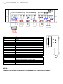
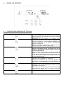
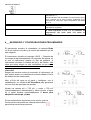
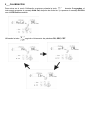
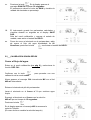
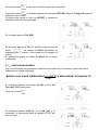
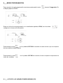
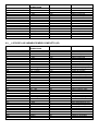
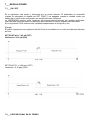
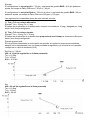
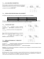
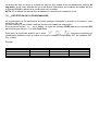
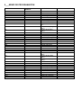
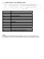
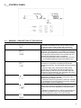
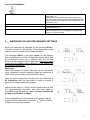
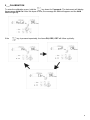
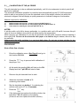
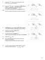
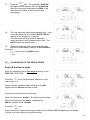
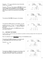
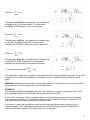
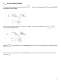
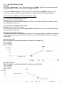
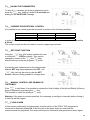
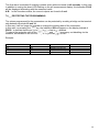
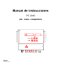
Manual de Instrucciones
PC 2000
pH – redox – temperatura
Manual:
Versión: 1.0
Índice:
1___DATOS TÉCNICOS
pág. 3
2___CONEXIONES EN LA BORNERA
pág. 4
3___PANEL DE MANDOS
3.1___DESCRIPCIÓN GENERAL DEL TECLADO
pág. 5
3.2___DESCRIPCIÓN GENERAL DE LOS INDICADORES LUMINOSOS
pág. 6
4___ENCENDIDO Y CONFIGURACIONES PRELIMINARES
pág. 7
5___CALIBRACIÓN INSTRUMENTO
pág. 8
5.1___CALIBRACIÓN SONDA pH
5.3___CALIBRACIÓN SONDA REDOX
5.3___VERIFICACIÓN SONDAS
pág. 9
pág. 11
pág. 12
6___MENÚ PROGRAMACIÓN
pág. 14
6.1___LISTA DE LAS VARIABLES MENÚ MÍNIMO (255)
6.1___LISTA DE LAS VARIABLES MENÚ COMPLETO (25)
pág. 15
pág. 15
7___REGULACIONES
pág. 16
7.1___ON / OFF
pág. 16
7.2___PROPORCIONAL EN EL TIEMPO
pág. 16
7,3___PROTECCIÓN PARÁMETROS
pág. 16
7.4___ REGULACIÓN PROPORCIONAL EN CORRIENTE
pág. 16
7.5___ FUNCIÓN SET POINT
pág. 17
7.6___ REGULACIÓN MANUAL Y CEBADO BOMBAS
pág. 17
7.7___ ALARMA FLUJO
pág. 17
7.8___ PROTECCIÓN DE LA PROGRAMACIÓN
pág. 17
8___MEMO DE PROGRAMACIÓN
pág. 18
1___DATOS TÉCNICOS
MEDIDAS:
GRADO DE PROTECCIÓN:
SECCIÓN DE LOS BORNES:
240 mm – 245 mm – 140 mm
IP65 (salvo BNC)
4mm2 , o diámetro 2,4 mm
ALIMENTACIÓN:
CONSUMO:
CAPACIDAD MÁXIMA EN RELÉS:
standard 230V ± 10% 50-60 Hz. Bajo pedido 115V
7W + 9W electroválvula
3A (con carga resistiva) 250 Vac
0…50 ° C
TEMPERATURA DE TRABAJO
TEMPERATURA DE ALMACENAJE
ESCALA DE MEDIDA DEL pH:
PRECISIÓN DE LA MEDIDA:
IMPEDANCIA DE ENTRADA:
COMPENSACIÓN EN TEMPERATURA:
AJUSTE DEL SET POINT:
REPETICIÓN REMOTA MEDIDA:
ESCALA DE MEDIDA DEL Redox:
PRECISIÓN DE LA MEDIDA:
AJUSTE DEL SET POINT:
SALIDA RETRANSMITIDA:
-10…+70 °C
0…14,00
± 0,1 pH
> 1013 ohm
MANUAL/AUTOMÁTICA 0…125 °C
ON / OFF
PAUSA / TRABAJO
PROPORCIONAL EN CORRIENTE:
0/4…20 mA separada galvánicamente
Configurable para transmisión medida o regulación
Resolución 255 puntos
Carga máxima 1 K ohm
0…999 mV
± 1 mv
ON / OFF
PAUSA / TRABAJO
PROPORCIONAL EN CORRIENTE:
0/4…20 mA separada galvánicamente
Configurable para transmisión medida o regulación
Carga máxima 1 K ohm
2___CONEXIONES EN LA BORNERA
N° Borne
Descripción
1
2
3
4–5
6–7
8–9
10 – 11
12 – 14
13 – 14
15
16
17
18
19
20
21
22
23
24
25
26
27
TIERRA
FASE
NEUTRO
RELÉ BOMBA PH
RELÉ BOMBA CLORO
RELE ALARMA
RELÉ E.V.
INPUT SEÑAL KEY
INPUT SEÑAL FLUS
NO UTILIZADO
NO UTILIZADO
INPUT PT100
INPUT PT100
INPUT PT100
OUTPUT FREC. PROP. PH POLO NEG.
OUTPUT FREC. PROP. PH POLO POS.
OUTPUT FREC. PROP. CL POLO NEG.
OUTPUT FREC. PROP. CL POLO POS.
OUTPUT CORR. PROP. PH POLO POS.
OUTPUT CORR. PROP. PH POLO NEG.
OUTPUT CORR. PROP. CL POLO POS.
OUTPUT CORR. PROP. PH POLO NEG.
pH
mV
NOTA:
HACIENDO UN PUENTE ENTRE LOS BORNES 17 Y 19 EL INSTRUMENTO RECONOCE QUE LA SONDA DE
TEMPERATURA ESTÁ DESCONECTADA Y HACE REFERENCIA A LA REGULACIÓN MANUAL.
3___PANEL DE MANDOS
3.1
5
6
DESCRIPCIÓN GENERAL DEL TECLADO
Visualiza en secuencia los set point configurados, si la
función está habilitada permite cambiar su valor. Utilizado
al mismo tiempo con la tecla ACK permite forzar el estado
de los relés de set.
Presionando la tecla aparece el mensaje ProG,
manteniendo pulsada la tecla durante 5 segundos se
entra en programación. Si la tecla está inhabilitada por la
protección efectuada en la bornera, presionándola
aparece el mensaje dIS.
Cuando se entra en programación, cada vez que se
presiona esta tecla se avanza un paso (step).
Hace retroceder los pasos de programación. Si se
mantiene presionada durante 5 segundos sale de la
función de programación, guarda todos los datos en
la memoria permanente.
Apagar el relé de alarma, pero si el estado de alarma
persiste, el LED correspondiente pasa de intermitente a
fijo y queda encendido hasta que se elimina la causa de la
alarma. Elimina un mensaje de error y restablece el valor
de defecto del dato errado
Aumenta el valor visualizado en la fase de programación.
Aumenta el valor visualizado con la tecla SET.
Visualiza la temperatura de referencia (manual o
automática). Si la temperatura es manual, presionar al
mismo tiempo con la tecla DOWN para su modificación.
Permite modificar el valor de temperatura. Reduce el valor
visualizado en la fase de programación. Reduce el valor
visualizado con la tecla SET.
Habilita la función manual, si se presiona al mismo tiempo
con la tecla SET permite forzar en manual los relés de
comando de las bombas.
Permite entrar en el Menú de calibración.
3.2 DESCRIPCIÓN GENERAL DE LOS INDICADORES LUMINOSOS
Display de la medida pH
Display de la medida Redox
Diodo LED bicolor. Indica el estado de la bomba pH
APAGADO
VERDE
ROJO
ROJO INTERMITENTE
La bomba del pH está apagada
El set point está activo pero la bomba está temporalmente
apagada
El set point está activo y la bomba está funcionando
En la fase de programación indica que el parámetro
visualizado se refiere al control del set point pH.
Diodo LED bicolor. Indica el estado de la bomba cloro
APAGADO
VERDE
ROJO
ROJO INTERMITENTE
La bomba del cloro está apagada
El set point está activo pero la bomba está temporalmente
apagada
El set point está activo y la bomba está funcionando
En la fase de programación indica que el parámetro
visualizado se refiere al control del set point del Redox.
Diodo LED Rojo. Indica un estado de ALARMA.
ROJO INTERMITENTE
ROJO
Se ha producido un estado de alarma; el relé alarma está
activo, para apagar la alarma presionar la tecla ACK.
Se ha reconocido una alarma con la tecla ACK pero la causa
que la había generado aún persiste, eliminando la causa el
LED Alarm se apaga.
Diodo LED Rojo. Indica un estado de parada total de las funciones del instrumento.
ROJO
Cuando está encendido señala el bloque temporal del
funcionamiento de las bombas, las salidas en corriente
quedan bloqueadas en el último valor retransmitido.
FUNCIONES DE CALIBRACIÓN
7 pH
4 pH
465 mv
El instrumento pide que el electrodo sea sumergido en
solución patrón 7 pH; por tanto está listo para efectuar
calibración del offset para el electrodo pH.
El instrumento pide que el electrodo sea sumergido en
solución patrón 4 pH; por tanto está listo para efectuar
calibración de la ganancia para el electrodo pH.
una
una
una
una
El instrumento pide que el electrodo sea sumergido en una solución
patrón 465 mV; así está listo para efectuar una calibración de la
ganancia para el electrodo Redox.
UNIDAD DE MEDIDA
°C
%
SEC.
mA
El valor numérico visualizado es una temperatura
expresada en °C
Si este indicador está encendido al mismo tiempo que el
led %, significa que el valor numérico visualizado es un
coeficiente de corrección según temperatura expresado
en %/°C.
El valor numérico visualizado es un porcentaje
El valor numérico visualizado es una unidad de tiempo
expresada en segundos
El valor numérico visualizado es un valor de corriente
de salida expresado en mA o es un parámetro de
programación que actúa sobre una salida en
corriente.
4___ENCENDIDO Y CONFIGURACIONES PRELIMINARES
El instrumento muestra, al encenderlo, el mensaje Redo
r 1.2 que indica el nombre y la versión del software que ha
sido cargada.
El instrumento visualiza el mensaje HOLD --- Después de
un tiempo de aproximadamente 10 segundos de espera, en
el cual el instrumento ejecuta un test de software, el
instrumento visualiza la medida del pH y del Redox, está
claro que estos valores no son verdaderos ya que no ha
sido efectuada la calibración de las sondas.
¡Atención!
Apagar las bombas antes de encender el instrumento ya
que podría causar una dosificación errónea debido al error
de medida recién mencionado.
Abrir el flujo del agua en el panel y configurar, con el
caudalímetro, un caudal de 60 litros/hora para garantizar
un buen flujo de agua para las sondas.
Ajustar los valores pH = 7.20 pH y redox = 700 mV
(aproximadamente) manualmente y hacer circular el agua
en el panel durante aproximadamente 2 horas para
adaptación sonda ph y redox.
En las explicaciones siguientes de los menús y de las
funciones del instrumento se utilizará este símbolo
para indicar las teclas a presionar.
5___CALIBRACIÓN
Para entrar en el menú Calibración mantener pulsada la tecla
durante 5 segundos, el
instrumento presenta el mensaje Hold Cal; después de dicho tiempo aparece el mensaje PH CAL
con el LED Hold encendido.
Utilizando la tecla
seguirán cíclicamente las palabras PH, ORP, CRT.
5.1___CALIBRACIÓN SONDA pH
El electrodo de pH debe ser recalibrado periódicamente hasta que, debido a su excesivo
agotamiento, es preciso cambiarlo.
La operación de calibración del electrodo es controlada de manera semiautomática por el
instrumento PC 2000, que reconoce de manera autónoma el valor de norma de la solución patrón
en la cual está sumergido el electrodo y que visualiza un parámetro de calidad para indicar el
grado de agotamiento de la sonda.
Material necesario para la calibración:
1)
2)
3)
Solución tampón 7 pH bien conservada (FRASCO N° 1)
Solución tampón 4 ó 9.22 pH bien conservada (FRASCO N° 3)
Agua limpia para lavar el electrodo (FRASCO N° 2)
NOTAS:
Una solución con 4 pH es siempre preferible a una solución con 9 ó 10 pH, se trata de un valor de
pH mucho más estable en el tiempo y sobre el cual no influye la temperatura.
Durante la fase de calibración se debe evitar introducir el electrodo en las soluciones tampón sin
primero lavarlo cuidadosamente. No secar el electrodo frotándolo con papel o trapos sino
dejarlo escurrir naturalmente.
Las soluciones tampón se deben guardar siempre en un sitio oscuro y fresco, se debe evitar el uso
de soluciones por más de un año.
PROCESO
Cerrar el flujo del agua.
1.
Entrar en el menú calibración (ver pág 8) y seleccionar
la función PH CAL
2.
Confirmar con la tecla
calibración de la sonda pH.
3.
Ahora aparece el mensaje CAL intermitente PH con el
led 7 pH intermitente.
4.
Extraer el electrodo de pH del portasondas.
5.
Lavar el electrodo en el frasco n° 2 que contiene agua
limpia.
6.
Sumergir el electrodo en el frasco n° 1 con la solución
7 pH durante 15 segundos.
7.
Presionar la tecla
8.
En el display aparece el mensaje 7.00 si reconoce la
solución tampón.
(En caso de error cambiar la solución tampón)
para proceder con una
9.
Presionar la tecla
es reconocida.
el valor de la solución tampón
10.
Presionar la tecla
en el display aparece el
mensaje OFFS PH. Esperar 30 segundos para la
calibración de la sonda.
El instrumento calcula el valor de OFFSET y visualiza
la calidad del electrodo en porcentaje.
11.
Al cabo de 5 segundos en el display aparece el
mensaje CAL PH y el led 4 pH intermitente
12.
Lavar el electrodo en el frasco n° 2 que contiene agua
limpia.
13.
Sumergir el electrodo en el frasco n° 3 con la solución
4 pH durante 15 segundos.
14.
Presionar la tecla
15.
En el display aparece el valor de la solución tampón
reconocida.
(En caso de error cambiar la solución tampón)
16.
Si se utiliza una diferente se debe corregir el valor
de la solución tampón con las teclas
17.
Presionar la tecla
. En el display aparece el
mensaje GAIN PH. Esperar 30 segundos.
El instrumento calcula el valor de GAIN y visualiza la
calidad del electrodo en porcentaje.
18.
El instrumento guarda los parámetros calculados y
visualiza durante un segundo en el display SAVE
PAR.
Sale del menú calibración y regresa al estado de
medida, resta activo el estado de HOLD.
19.
Poner de nuevo el electrodo en el portasondas y abrir
de nuevo el flujo del agua ajustándolo en 60
litros/hora, presionar la tecla
para eliminar el estado de HOLD.
5.2___CALIBRACIÓN SONDA REDOX
Cerrar el flujo del agua.
Entrar en el menú calibración (ver pág 8) y seleccionar la
función ORP CAL
Confirmar con la tecla
calibración de la sonda redox.
para proceder con una
Ahora aparece el mensaje CAL intermitente MV con el led
465 mV intermitente.
Extraer el electrodo de pH del portasondas.
Lavar el electrodo en el frasco n° 2 que contiene agua
limpia.
Sumergir el electrodo en el frasco con la solución
465 mV por un tiempo de 15 segundos.
Presionar la tecla
En el display aparece el mensaje 465 si reconoce la
solución Tampón.
(En caso de error cambiar la solución tampón)
Presionar la tecla
el valor de la solución tampón es reconocida.
Presionar la tecla
, en el display aparece el mensaje OFFS MV. Esperar 30 segundos para la
calibración de la sonda.
El instrumento calcula el valor de OFFSET y visualiza la
calidad del electrodo en porcentaje.
En el display aparece CAL END
En el display aparece 0 THL. Es posible configurar con las
teclas
un tiempo de HOLD (expresado en
segundos) para consentir a las sondas que se adapten al
circuito.
El instrumento queda en estado de HOLD por el tiempo
configurado.
5.3___VERIFICACIÓN SONDAS
Una vez terminados los procesos de calibración es posible leer los valores en porcentaje de la
calidad de las sondas calibradas.
Entrar en el menú calibración (ver pág 8) y seleccionar la función Ctr
CAL.
En el display aparece el mensaje Ctr CAL con los led
7pH, 4pH, CL2 intermitentes.
Presionar la tecla
En el display aparece o100 Ctr con el led 7 pH y %
encendido, el instrumento indica la calidad OFFSET del
electrodo pH.
Presionar la tecla
En el display aparece G100 Ctr con el led 4 pH y % encendido, el instrumento indica la calidad
GAIN del electrodo pH.
Presionar la tecla
En el display aparece o100 Ctr con el led Cl2 y %
encendido, el instrumento indica la calidad OFFSET del
electrodo Redox.
Presionar la tecla
En el display aparece G100 Ctr con el led Cl2 y %
encendido, el instrumento indica la calidad GAIN del
electrodo Redox.
Para salir del menú presionar la tecla
Las indicaciones de calidad del electrodo se deben considerar por separado, un grado bajo de
calidad en una de las dos, indica escasa calidad aunque la otra indicación sea buena.
ATENCIÓN: Verificar siempre la calidad de las soluciones de muestra, deben ser nuevas, de color
homogéneo y no deben formarse algas dentro.
EJEMPLO:
Supongamos que en la calibración con 7 pH la calidad resulte ser del 10%, mientras que en la
calibración con 4 pH la calidad resulte ser del 98%.
En tal caso es evidente que el elemento de referencia del electrodo se ha estropeado
precozmente. Este fenómeno por ejemplo es típico en las instalaciones de cloración en que se
efectúan cloraciones SHOCK que tienden a contaminar la referencia del electrodo.
En este caso sería una buena solución cerrar el sistema de medida en la fase de supercloración o
utilizar los electrodos previstos de doble barrera, expresamente construidos para no ser
perjudicados por el cloro disuelto en el agua.
6___MENÚ PROGRAMACIÓN
Para acceder al menú programación mantener presionada la tecla
el display aparece PROG
durante 5 segundos. En
Entra en la función de programación, es visualizada la palabra 0 PAS, con las teclas
configurar el número de contraseña.
Presionando la tecla
con la palabra 255 PAS se accede al menú mínimo que se compone
de las variables indispensables.
Presionando la tecla
todas las variables.
con la palabra 25 PAS se accede al menú completo compuestos de
6.1___LISTA DE LAS VARIABLES MENÚ MÍNIMO (255)
VARIABLES
LÍMITES
CONSENTIDOS
VALORES POR DEFECTO
COMENTARIO
0…14,00
0…SET
SET…14,00
7,20
6,80
7,60
SET POINT pH
Alarma mínimo pH
Alarma máximo pH
700
600
800
SET POINT redox
Alarma mínimo redox
Alarma máximo redox
ON
ON
ON
Habilita la Tecla Set
Habilita la Tecla Cal
Habilita la Tecla Man
CONFIGURACIONES PH
SET
ALL
ALH
CONFIGURACIONES Redox
SET
0…999 mV
ALL
0…SET
ALH
SET…999
HABILITACIONES
SET
CAL
MAN
ON/OFF
ON/OFF
ON/OFF
6.2___LISTA DE LAS VARIABLES MENÚ COMPLETO (25)
VARIABLES
LÍMITES
CONSENTIDOS
VALORES POR DEFECTO
COMENTARIO
SET
REL
ALL
ALH
PRS
HIS
DEL
Ton
Tof
BND
RMA
PHS
PHE
BP
0…14,00
ACID/ALCA
0…SET
SET…14,00
NO / NC
0,02…1,40
0…255
0…999 seg
0…999 seg
0,00…2,00 Ph
0-20/4-20
0…10,00
PHS…14,00
0,50…2,80
7,20
ACID
6,80
7,60
NO
0,05
0
0
0
0,00
4-20
0
14,00
OFF
SET POINT pH
Tipo de regulación
Alarma mínimo pH
Alarma máximo pH
Estado relé pH
Histéresis
Tiempo de retraso dos. pH
Tiempo de On (Reg. Puls.)
Tiempo de Off (Reg. Puls.)
Banda de Guardia
Dinámica Output en mA
Valor inicial para reg. mA
Valor final para reg. mA
Banda proporcional
CONFIGURACIONES Redox
SET
PRS
ALL
ALH
HIS
DEL
Ton
Tof
BND
RMA
RDS
RDE
BP
0…999 mV
NO / NC
0…SET
SET…999
0…0,50
0…255
0…999 seg
0…999 seg
0…200
0-20/4-20
0…999
RDS…999
0…200
700
NO
600
800
0
0
0
0
0
4-20
0
999
OFF
SET POINT redox
Estado relé Redox
Alarma mínimo redox
Alarma máximo redox
Histéresis
Tiempo retraso dos. redox
Tiempo de On (Reg. Puls.)
Tiempo de Off (Reg. Puls.)
Banda de Guardia
Dinámica Output en mA
Valor inicial para reg. mA
Valor final para reg. mA
Banda proporcional
ON/OFF
ON/OFF
ON/OFF
ON
ON
ON
Habilita la Tecla Set
Habilita la Tecla Cal
Habilita la Tecla Man
CONFIGURACIONES PH
HABILITACIONES
SET
CAL
MAN
7___REGULACIONES
7.1___ON / OFF
Es la regulación más simple y elemental que se puede efectuar. El dosificador es encendido
cuando se sobrepasa la medida del SET POINT y es apagado cuando la medida vuelve por
debajo de un cierto valor configurado que es definido como histéresis.
La HISTÉRESIS permite evitar continuas activaciones-desactivaciones del aparato dosificador,
una histéresis reducida mejora la regulación pero conlleva un mayor desgaste del dosificador.
En la regulación PULS tenemos tres variables fundamentales a configurar y son:
Ejemplo:
El gráfico representa una regulación del Set Point de la medida con un valor de histéresis diferente
de cero.
SET POINT pH = 7,20 pH (SET)
Histéresis = 0,10 pH (HIS)
SET POINT CL = 0,90 ppm (SET)
Histéresis = 0,10 ppm (HIS)
7.2___PROPORCIONAL EN EL TIEMPO
Ejemplo:
Si configuramos un set point pH = 7,20 pH y una banda de guardia BND = 0,20 pH podemos
ajustar un tiempo de Ton y Tof entre 7,20 pH y 7,40 pH.
Si configuramos un set point Redox = 700 mV de cloro y una banda de guardia BND = 50 mV
podemos ajustar un tiempo de Ton y Tof entre 650 ppm y 700 ppm.
Las regulaciones consentidas dentro de este intervalo son dos:
1) Ton y Tof con valores diferentes
Ejemplo: Ton = 10 seg Tof = 5 seg.
El tiempo de dosificación de la bomba será, siempre encendida por 10 seg y apagada por 5 seg.
dentro de la franja configurada.
2) Ton y Tof con valores iguales
Ejemplo: Ton = 10 seg Tof = 10 seg.
El tiempo de dosificación de la bomba será proporcional en el tiempo al acercarse al Set point
dentro de la franja configurada.
Ejemplo proporcional:
En los gráficos presentados a continuación se describe la regulación proporcional antedicha;
además se ha representado con una línea punteada la regulación que se tendría si el operador
configurara un valor de histéresis (HIS).
Set Point = 7,20 pH
HIS = 0.10 pH (la regulación es la línea punteada)
Ton = 10 Seg.
Tof = 10 Seg.
BND = 0.20 pH
Set Point = 700 mV
HIS = 50 mV (la regulación es la línea punteada)
Ton = 10 Seg.
Tof = 10 Seg.
BND = 50 mV
7,3___SALVAGUARDIA PARÁMETROS
Para guardar los parámetros configurados en el menú de
programación presionar la tecla
durante 5 segundos
y esperar el mensaje SAVE PAR.
7.4___ REGULACIÓN PROPORCIONAL EN CORRIENTE
La regulación proporcional en corriente es posible configurarla con las variables:
PHS
PHE
RDS
RDE
0 ph
14,00 ph
0 mV
999 mV
Valor inicial para reg. mA
Valor final para reg. mA
Valor inicial para reg. mA
Valor final para reg. mA
Para poder ajustarla es necesario tener una bomba con entrada en corriente 0-20 mA ó 4-20 mA.
La salida en corriente se puede utilizar también para un registrador a papel.
7.5___ FUNCIÓN SET POINT
La tecla
permite al usuario visualizar
cíclicamente los SET POINT y modificarlos con las
teclas
sin tener que entrar en la programación.
Si se efectúa la protección en bornera y en el paso
SET se ha programado OFF, al pulsar la tecla
es posible sólo visualizar los SET
POINT sin poder modificarlos.
7.6___REGULACIÓN MANUAL Y CEBADO DE
LAS BOMBAS.
La tecla
mantenida pulsada, permite activar en secuencia los relés de comando de las
bombas pH y Redox (cloro), presionar la tecla
.
Esta función es de utilidad para operaciones de cebado de las bombas.
Atención: Si la bomba está controlada en corriente hay que configurar en manual antes de forzar
el arranque desde el teclado.
7.7___ALARMA FLUJO
En los bornes 13 y 14 hay conectado un sensor de flujo situado en el rebosador piezométrico del
POOL TOP, si se produce una bajada del flujo del agua tal que perjudique la medida, el
instrumento actúa bloqueando la cloración y generando una alarma.
La alarma de flujo se activa si la señal de falta de flujo queda activa continuamente durante 40
segundos, en tal caso, además de ver el led Alarma intermitente en el display de medida del pH,
el mensaje FLUS se alterna a la visualización de la medida.
NOTA: En el estado de alarma flujo las salidas en corriente son forzadas a 0 mA.
7.8___PROTECCIÓN DE LA PROGRAMACIÓN
La programación de los parámetros se puede proteger realizando un puente en la bornera, entre
los bornes 12 y 14.
De esta manera no es posible modificar los datos de trabajo del instrumento.
Si se presiona la tecla
en el display, en lugar del mensaje PROG aparece el mensaje DIS
para indicar que dicha función está inhabilitada.
Para tener la protección también en la tecla
,
,
, efectuar previamente la
inhabilitación software como se indica en el menú completo configurando OFF las variables SET,
CAL y MAN.
Ejemplo:
HABILITACIONES
SET
CAL
MAN
OFF
OFF
OFF
Inhabilita la Tecla Set
Inhabilita la Tecla Cal
Inhabilita la Tecla Man
8___MEMO DE PROGRAMACIÓN
VARIABLES
VALORES POR
DEFECTO
COMENTARIO
SET
REL
ALL
ALH
PRS
HIS
DEL
7,20
ACID
6,80
7,60
NO
0,05
0
Ton
0
Tof
0
BND
RMA
PHS
PHE
BP
0
4-20
0
14,00
OFF
SET POINT pH
Tipo de regulación
Alarma mínimo pH
Alarma máximo pH
Estado relé pH
Histéresis
Tiempo de retraso dos.
pH
Tiempo de On (Reg.
Puls.)
Tiempo de Of (Reg.
Puls.)
Banda de Guardia
Dinámica Output en mA
Valor inicial para reg. mA
Valor final para reg. mA
Banda proporcional
CONFIGURACIONES PH
CONFIGURACIONES Redox
SET
700
PRS
NO
SET POINT redox
Estado relé Redox
ALL
ALH
HIS
DEL
600
800
0
0
Ton
0
Tof
0
BND
RMA
RDS
RDE
BP
0
4-20
0
999
OFF
Alarma mínimo redox
Alarma máximo redox
Histéresis
Tiempo de retraso dos.
redox
Tiempo de On (Reg.
Puls.)
Tiempo de Of (Reg.
Puls.)
Banda de Guardia
Dinámica Output en mA
Valor inicial para reg. mA
Valor final para reg. mA
Banda proporcional
ON
ON
ON
Habilita la Tecla Set
Habilita la Tecla Cal
Habilita la Tecla Man
HABILITACIONES
SET
CAL
MAN
CONFIGURACIONES
Instruction Manual
PC 2000
(Cod.136314)
pH – redox – temperature
Manual:0000136314
Version: 2.0
Products: PC2000
Table of contents:
1___TECHNICAL SPECIFICATIONS
Page 3
2___CONNECTION TO THE TERMINAL STRIP
Page 4
3___CONTROL PANEL
Page 5
Page 5
Page 6
3.1___GENERAL DESCRIPTION OF THE KEYPAD
3.2___GENERAL DESCRIPTION OF THE SIGNALLING LAMPS
4___SWITCHING ON AND PRELIMINARY SETTINGS
Page 7
5___CALIBRATING THE INSTRUMENT
Page 8
5.1___CALIBRATION OF THE pH PROBE
Page 9
5.3___CALIBRATION OF THE REDOX PROBE
Page 11
5.3___CHECKING THE PROBES
Page 12
6___PROGRAMMING MENU
6.1___LIST OF VARIABLES IN THE SHORT MENU (255)
6.1___LIST OF VARIABLES IN THE FULL MENU (25)
7___CONTROL MODES
Page 14
Page 15
Page 15
Page 16
7.1___ON / OFF
Page 16
7.2___PROPORTIONAL IN TIME
Page 16
7.3___SAVING THE PARAMETERS
Page 16
7.4___ CURRENT-PROPORTIONAL CONTROL
Page 16
7.5___ SET-POINT FUNCTION
Page 17
7.6___ MANUAL CONTROL AND PRIMING OF THE PUMPS
Page 17
7.7___ FLOW ALARM
Page 17
7.8___ PROTECTING THE PROGRAMMING
Page 17
8___PROGRAMMING MEMO
Page 18
2
1___TECHNICAL SPECIFICATIONS
SIZE:
CLASS OF PROTECTION:
CROSS-SECTION OF TERMINALS:
H–L–D
POWER SUPPLY REQUIREMENTS:
CURRENT ABSORPTION:
MAXIMUM CAPACITY ON RELAYS:
standard 230V r 10% 50-60 Hz, 115V on request
7W + 9W for solenoid valve
3A (on a resistive load), 250 VAC
WORKING TEMPERATURE
STORAGE TEMPERATURE
0 to 50 ° C
-10 to +70 °C
IP65 (excluding BNC)
4 mm2 , or diameter 2.4 mm
SCALE OF MEASUREMENT OF pH: 0 to 14.00
RESOLUTION OF MEASUREMENT: r 0.1 pH
INPUT IMPEDANCE:
> 1013 Ohms
TEMPERATURE OFFSETTING:
MANUAL/AUTOMATIC, 0 to 125 °C
CONTROL IN RESPECT OF SET POINT:
ON/OFF
BREAK / WORK
CURRENT-PROPORTIONAL
REMOTE REPETITION OF MEASUREMENT: 0/4 to 20 mA , galvanically separated
Fully configurable for re-transmission of measurement or control
functions
Resolution: 255 dots
Maximum load: 1 K Ohm
SCALE OF MEASUREMENT OF Redox:
ACCURACY OF MEASUREMENT:
CONTROL IN RESPECT OF SET POINT:
RE-TRANSMITTED OUTPUT :
0 to 999 mV
r 1 mV
ON/OFF
BREAK / WORK
CURRENT-PROPORTIONAL
0/4 to 20 mA, galvanically separated
Fully configurable for re-transmission of measurement or control
functions
Maximum load: 1 K Ohm
3
2___CONNECTIONS TO THE TERMINAL STRIP:
Terminal Nr
1
2
3–4
5–6
7–8
9 – 10
11 – 12
13
14
15
16
17
18 – 19
19 – 20
21
22
23
24
25
26
27
28
Description
NEUTRAL
PHASE
RELAY S.V. (SOLENOID VALVE)
RELAY PH PUMP
RELAY CHLORINE PUMP
RELAY ALARM
NOT USED
NOT USED
NOT USED
PT100 INPUT
PT100 INPUT
PT100 INPUT
FLUS SIGNAL INPUT
KEY SIGNAL INPUT
PROP. CORRENT. OUTPUT CL NEGATIVE POLE
PROP. CORRENT. OUTPUT CL POSITIVE POLE
PROP. CORRENT. OUTPUT PH NEGATIVE POLE
PROP. CORRENT. OUTPUT PH POSITIVE POLE
PROP. FREQU. OUTPUT CL NEGATIVE POLE
PROP. FREQU. OUTPUT CL POSITIVE POLE
PROP. FREQU. OUTPUT PH NEGATIVE POLE
PROP. FREQU. OUTPUT PH POSITIVE POLE
NOTE:
IF A BRIDGE IS CREATED BETWEEN TERMINALS 15 AND 17 ,THE INSTRUMENT WILL
RECOGNISE THAT THE PT100 IS DISCONNECTED AND GOES INTO MANUAL CONTROL.
4
3___CONTROL PANEL
3.1
GENERAL DESCRIPTION OF THE KEYPAD
This key displays the set points entered, in sequence. If
this function is enabled, the key can be used to change
the set-point value. Used together with the ACK key
enables the status of the set-point relays to be forced.
When this key is pressed, the wording ProG will be
displayed. If it is held down for 5 seconds, the instrument
will go into the programming mode. If the key is inhibited
by the protection implemented on the terminal strip, the
indication dlS will appear when it is pressed.
When the programming mode is entered, each time this
key is pressed programming will move forward by one
step.
This moves back through the programming steps. If it is
held down for 5 seconds, the instrument will exit the
programming function, and all the data will be permanently
stored.
It resets the alarm relay, however if the alarm status
persists the corresponding LED will stop flashing and
remain steady on until the cause of the alarm has been
eliminated. It will eliminate an error message and resets
the incorrect datum to the default value.
Pressing this key will increment the value displayed while
programming. Pressing it will also increment the value
displayed by pressing the SET key.
It causes the reference temperature ( manual or automatic
) to be displayed. If the temperature is manual it should be
pressed together with the DOWN key.
This key can be used to change the temperature value. It
decrements the value being displayed while programming.
It decrements the value displayed on pressing the SET
key.
It enables the manual function, and if it is pressed at the
same time as the SET key, it can be used to force the
relays controlling the pumps in the manual mode.
This key enables the Calibration menu to be entered.
5
3.2
GENERAL DESCRIPTION OF THE SIGNALLING LAMPS
pH measurement display
Redox measurement display
Two-coloured LED. It indicates the status of the pH pump
OFF
GREEN
RED
FLASHING RED
The pH pump is OFF.
The set point is active but the pump is temporarily OFF.
The set point is active and the pump is ON.
During programming it indicates that the parameter being
displayed refers to control of the pH set point.
Two-coloured LED. It indicates the status of the chlorine pump
OFF
GREEN
RED
FLASHING RED
The chlorine pump is OFF.
The set point is active but the pump is temporarily OFF.
The set point is active and the pump is ON.
During programming it indicates that the parameter being
displayed refers to control of the Redox set point.
Red LED. It indicates an ALARM status.
FLASHING RED
RED
An alarm status has occurred. The alarm relay has been
activated. To reset the alarm press the ACK key.
An alarm has been acknowledged by pressing the ACK
key, however the cause that generated the alarm is still
present. Once the cause is removed the alarm LED will
extinguish.
Red LED. It indicates a status of total stoppage of the functions of the instrument.
RED
When this LED is illuminated, it signals a temporary block of operation of the pumps. The current
outputs remain locked on the last value that was re-transmitted.
CALIBRATION FUNCTIONS
7 pH
4 pH
465 mv
The instrument is prompting you to dip the electrode into a
sample solution a 7 pH it is therefore ready to carry out
calibration of the offset on the pH electrode.
The instrument is prompting you to dip the electrode into a
sample solution with a pH of 4. It is therefore ready to
carry out calibration of the gain on the pH electrode.
The instrument is prompting you to dip the electrode into a
sample solution at 465 mV. It is therefore ready to carry out
calibration of the gain on the Redox electrode.
6
UNITS OF MEASUREMENT
°C
%
SEC.
mA
The numerical value being displayed is a temperature
expressed in °C.
If this indicator is illuminated at the same time as the %
sign, this means that the numerical value being displayed
a correction factor that depends on the temperature. It is
expressed in %/°C.
The numerical value being displayed is a percentage.
The numerical value being displayed is a unit of time
expressed in seconds
The numerical value being displayed is an output current
value expressed in mA, or is a programming parameter
that acts on a current output.
4___SWITCHING ON AND PRELIMINARY SETTINGS
When the instrument is switched on, the message Redo r
1.2 will be shown on the display. This indicates the name
and the revision number of the software loaded.
The message HOLD --- will then appear on the display.
After a waiting time of about 10 seconds, during which time
the instrument carries out a software test, the pH and
Redox values measured will be displayed. Obviously, these
values are not reliable, since calibration of the probes has
not yet been carried out.
Warning!!!
Switch the pumps off before switching on the instrument,
since otherwise incorrect metering might be caused as a
result of the error measurement referred to above.
Open the flow of water into the panel and set a flow rate of
60 Litres/hour with the flow-meter in order to ensure a
good flow of water towards the probes.
Adjust the pH value to 7.20 pH and the Redox value to 700
mV (approximately) manually, and allow the water to
circulate through the panel for about 2 hours to enable the
pH and redox probes to adapt.
In the explanations provided below on the menus and the
functions of the instrument, the symbol
will be used to
indicate the keys to be pressed.
7
5___CALIBRATION
To enter the calibration menu, hold the
key down for 5 seconds. The instrument will display
the message Hold Cal. After this lapse of time, the message CL CAL will appear and the Hold
LED will light up.
If the
key is pressed repeatedly, the items PH, ORP, CRT will follow cyclically.
8
5.1___CALIBRATION OF THE pH PROBE
The pH electrode has to be re-calibrated periodically, until it is too exhausted, at which point it will
have to be replaced.
The electrode calibration operation is controlled semi-automatically by the PC 2000 instrument,
which is able to recognise on its own the standard value of the sample solution into which the
electrode is dipped, and will display a quality parameter to indicate its degree of exhaustion.
Material required for calibration:
1)
2)
3)
Buffer solution with a pH of 7, properly preserved (BOTTLE N° 1)
Buffer solution with a pH of 4 or 9.22, properly preserved (BOTTLE N° 3)
Clean water for washing the electrode (BOTTLE N° 2)
NOTES:
A solution with a pH of 4 is always preferable to a solution with a pH of 9 or 10, because this pH
value is far more stable in time and is not influenced by the temperature.
While carrying out calibration do not dip the electrode into the buffer solutions without washing it
thoroughly first. Do not rub the electrode with paper or a cloth to dry it. Instead, allow it to drip
dry naturally.
Always store the buffer solutions in a cool and dark place. Do not use a given solution for any
longer than one year.
PROCEDURE
Shut off the flow of water.
1.
Enter the calibration menu (See Page 8) and go to
the function PH CAL
2.
Press the
the pH probe.
3.
At this point the wording CAL will flash on the PH
Display and the 7 pH LED will start to flash.
4.
Remove the pH electrode from its tank.
5.
Wash the electrode in bottle n° 2
containing clean water.
6.
Dip the electrode into bottle n° 1 containing the
solution with a pH of 7 for 15 seconds.
7.
Press the
8.
If the instrument recognises the buffer solution, the
indication 7.00 will appear on the display.
(If there is an error replace the buffer solution)
key to proceed with calibration of
key.
9
9.
Press the
key to confirm the value of the
buffer solution as recognised.
10.
Press the
key. The indication OFFS PH will
appear on the display. Wait 30 seconds
for the probe to be calibrated.
The instrument will calculate the OFFSET value
and
show the quality of the electrode as a percentage.
11.
5 seconds later the indication CAL PH will appear
on the display and the 4 pH LED will start to flash.
12.
Wash the electrode in bottle n° 2
containing clean water.
13.
Dip the electrode into bottle n° 3
containing the solution with a pH of 4 for 15 seconds.
14.
Press the
15.
The recognised value of the buffer solution will
appear on the display.
(If there is an error replace the buffer solution)
16.
If you are using a different buffer solution, correct
the value shown using the
keys.
key.
10
17.
Press the
key. The indication GAIN PH
will appear on the display. Wait for 30 seconds
while the instrument calculates the GAIN. It will
then show the quality of the electrode as a
percentage.
18.
The instrument will save the parameters that have
been calculated and the wording SAVE PAR will
appear on the display for 1 second.
The instrument will then exit the calibration
menu and return to the measurement mode. The
HOLD status will remain active.
19.
Place the electrode back into its tank and open
the flow of water again, setting it at 60 litres/hour.
Press the
key to leave the HOLD status.
5.2___CALIBRATION OF THE REDOX PROBE
Shut off the flow of water.
Enter the calibration menu (See page 8) and go to the
ORP CAL FUNCTION.
Press the
redox probe.
key to proceed with calibration of the
At this point the indication CAL will flash on the MV
display and the 465 mv will start to flash.
Remove the pH electrode from its tank.
Wash the electrode in bottle n° 2 containing clean water.
Dip the electrode into the bottle containing the
465 mv solution for 15 seconds.
Press the
key.
If the instrument recognises the buffer solution, the indication 465 will appear on the display.
(If there is an error replace the buffer solution)
11
Press the
key to confirm the value of the buffer
solution as recognised.
Press the
key. The indication OFFS MV will appear
on the display. Wait 30 seconds for the probe to be
calibrated. The instrument will calculate the OFFSET value
and show the quality of the electrode as a percentage
value.
The indication CAL END will appear on the display.
The indication 0 THL appears on the display. It is now
possible to use the
and
keys to a HOLD time
(expressed in seconds) to allow the probes to adapt to
the circuit.
The instrument will remain in the HOLD status for the
time that has been set.
5.3___CHECKING THE PROBES
Once the calibration procedures have been completed, it is possible to read the percentage values of the quality of the
calibrated probes again.
Enter the calibration menu (See page 8) and go to the Ctr CAL function.
The indication Ctr CAL will appear on the display and
the 7pH, 4pH and CL2 LEDs will start to flash.
Press the
key.
The indication o100 Ctr will appear on the display, with
the 7 pH and % LEDs illuminated. The instrument
indicates the OFFSET quality of the pH electrode.
12
Press the
key.
The indication G100 Ctr will appear on the display with
the 4 pH and % LEDs illuminated. The instrument
indicates the GAIN quality of the pH electrode.
Press the
key.
The indication o100 Ctr will appear on the display with
the Cl2 and % LEDs illuminated. The instrument
indicates the OFFSET quality of the Redox electrode.
Press the
key.
The indication G100 Ctr will appear on the display with
the Cl2 and % LEDs illuminated. The instrument
indicates the GAIN quality of the Redox electrode.
To exit the menu press the
key.
The indications concerning the quality of the electrode should be considered separately. A low level
of quality for one of the two readings is an indication of poor quality even if the other reading is
good.
WARNING: Always check the quality of the sample solutions. They must be fresh, have an evenly
distributed colour and no algae must have formed in them.
EXAMPLE:
Let us suppose that when calibrating with the 7 pH solution the quality is found to be 10%, while
when calibrating with the 4 pH solution the quality is found to be 98%.
In this case it is obvious that the reference element of the electrode was prematurely damaged.
This is typical, for instance, in chlorination systems in which shock chlorination is carried out, as
this tens to pollute the reference element of the electrode.
In this case, it would be a good rule to exclude the measuring system when carrying out the
superchlorination, or to use a special electrode with a double barrier, designed specifically to
withstand damage caused by the chlorine dissolved in the water.
13
6___PROGRAMMING MENU
To access the programming menu hold the
will appear on the display.
key down for 5 seconds. The message PROG
On entering the programming function, the first item - 0 PAS – will appear on the display. Use the
keys to set the password number.
and
When the
key is pressed with the item 255 PAS displayed, the short menu containing only the essential variables
will be accessed.
When the
key is pressed with the item 25 PAS displayed, the full menu containing all the available variables will
be accessed.
14
6.1___LIST OF VARIABLES ON THE SHORT MENU (255)
VARIABLES
PERMITTED LIMITS
DEFAULT VALUES
COMMENTS
0…14,00
0…SET
SET…14,00
7,20
6,80
7,60
pH SET POINT
Minimum PH alarm
Maximum pH alarm
0…999 mV
0…SET
SET…999
700
600
800
Redox SET POINT
Minimum redox alarm
Maximum redox alarm
ON/OFF
ON/OFF
ON/OFF
ON
ON
ON
Enables the SET key
Enables the CAL key
Enables the MAN key
PH SETTINGS
SET
ALL
ALH
Redox settings
SET
ALL
ALH
ENABLING
SET
CAL
MAN
6.2___LIST OF VARIABLES ON THE FULL MENU (25)
VARIABLES
PERMISSIBLE LIMITS
DEFAULT VALUES
COMMENTS
0…14,00
ACID/ALCA
0…SET
SET…14,00
NO / NC
0,02…1,40
0…255
0…999 sec
0…999 sec
0,00…2,00 Ph
0-20/4-20
0…10,00
PHS…14,00
0,50…2,80
7,20
ACID
6,80
7,60
NO
0,05
0
0
0
0,00
4-20
0
14,00
OFF
SET POINT pH
Type of control
Minimum pH alarm
Maximum pH alarm
Status of the pH relay
Hysteresis
Delay time, pH metering
ON time (Pulsed control)
OFF time (Pulsed control)
Safety range
Output dynamics in mA
Initial value for mA control
Final value for mA control
Proportional band
0…999 mV
NO / NC
0…SET
SET…999
0…0,50
0…255
0…999 sec
0…999 sec
0…200
0-20/4-20
0…999
RDS…999
0…200
700
NO
600
800
0
0
0
0
0
4-20
0
999
OFF
SET POINT redox
Status of the redox relay
Minimum redox alarm
Maximum redox alarm
Hysteresis
Delay time, redox metering
ON time (Pulsed control)
OFF time (Pulsed control)
Safety range
Output dynamics in mA
Initial value for mA control
Final value for mA control
Proportional band
ON/OFF
ON/OFF
ON/OFF
ON
ON
ON
Enables the SET key
Enables the CAL key
Enables the MAN key
PH SETTINGS
SET
REL
ALL
ALH
PRS
HIS
DEL
Ton
Tof
BND
RMA
PHS
PHE
BP
Redox settings
SET
PRS
ALL
ALH
HIS
DEL
Ton
Tof
BND
RMA
RDS
RDE
BP
ENABLING
SET
CAL
MAN
15
7___CONTROL MODES
7.1___ON / OFF
This is the simplest and most elementary control mode that can be implemented. The metering
device switches on as soon as the measured value exceeds the SET POINT and switches off when
the measured value drops to below a given pre-set value that is defined as HYSTERESIS.
HYSTERESIS makes it possible to prevent the metering device from switching constantly on and
off. Limited hysteresis improves control but to the detriment of the metering device, which will be
subjected to greater wear.
With PULS control, there are three basic variables to be set, which are:
Example:
The diagram shows control of the measurement Set Point with a hysteresis value other than
nought.
SET POINT pH = 7,20 pH (SET)
Hysteresis = 0,10 pH (HIS)
SET POINT CL = 0.90 ppm (SET)
Hysteresis = 0.10 ppm (HIS)
16
7.2___PROPORTIONAL IN TIME
Example:
If we enter a pH set point = pH 7.20 and a safety range BND = pH 0.20, we can control the pH,
keeping it between 7.20 and 7.40 with the Ton and Tof times.
If we enter a Redox set point = 700 mV of chlorine and a safety range BND = 50 mV, we can
control the content, keeping it between 650 ppm and 700 ppm with the Ton and Tof times.
There are two permissible control modes within this range:
1) Ton and Tof having different values
Example: Ton = 10 sec Tof = 5 sec.
The metering time of the pump will always be: ON for 10 seconds and OFF for 5 seconds, within
the range that has been set.
2) Ton and Tof having the same values
Example: Ton = 10 sec Tof = 10 sec.
The metering time of the pump will be proportional in time as the Set Point is approached within
the range that has been set.
Example of proportional control:
Proportional control as described above is shown in the following diagrams. In addition, the type of
control that would be implemented if the operator were to set a hysteresis (HIS) value is shown as
a dotted line.
Set Point = pH 7.20
HIS = 0.10 pH (the control implemented is shown as a dotted line)
Ton = 10 Secs
Tof = 10 Secs
BND = pH 0.20
Set Point = 700 mV
HIS = 50 mV (the control implemented is shown as a dotted line)
Ton = 10 Secs
Tof = 10 Secs
BND = 50 mV
17
7.3___SAVING THE PARAMETERS
To save the parameters set in the programming menu,
press the
key, holding it down for 5 seconds and
waiting for the SAVE PAR message.
7.4___CURRENT-PROPORTIONAL CONTROL
It is possible to set current-proportional control by means of the following variables:
PHS
PHE
RDS
RDE
pH 0
pH 14,00
0 mV
999 mV
Initial value for mA control
Final value for mA control
Initial value for mA control
Final value for mA control
In order to control the metering, it is necessary to have a pump with a current input of 0-20 mA or
4-20 mA.
The current output can also be used to connect a paper-type recorder.
7.5___SET-POINT FUNCTION
Using the
key, this function enables the user
to view the SET POINTs cyclically. They can be
changed by means of the
and
keys
without having to enter the programming mode.
If protection was implemented on the terminal strip
and the SET step was programmed as OFF, the
Key can only be used to view the SET
POINTs, without it being possible to change them.
7.6___MANUAL CONTROL AND PRIMING OF
THE PUMPS.
If the
is held down, it is possible to activate the control relays of the pH and Redox (chlorine)
pump in sequence by pressing the
key.
.
This function is useful for priming the pumps.
Warning: If the pump is current-controlled, it is necessary to configure it manually before forcing it
to start up via the keypad.
7.7___FLOW ALARM
A flow sensor positioned in the piezometric overflow device of the POOL TOP equipment is
connected to terminals 13 and 14. If the flow rate of the water drops so much that the
measurements are prejudiced, this sensor will stop the chlorination and generate an alarm signal.
18
The flow alarm is activated if enabling remains active without a break for 40 seconds. In this case,
in addition to seeing the alarm LED flashing on the pH measurement display, the indication FLUS
will be displayed alternating with the measured value.
N.B. In the flow alarm status, the current outputs are forced to 0 mA.
7.8___PROTECTING THE PROGRAMMING
The values programmed for the parameters can be protected by creating a bridge on the terminal
strip between terminals 12 and 14.
In this way, it will no longer be possible to change the working data of the instrument.
In this case, on pressing the
key, the indication DIS will appear on the display instead of
PROG , to indicate that the programming function has been disabled.
To extend the protection also to the
,
and
keys, carry out disabling via the
software, as indicated in the full menu by setting the variables to OFF.
Example:
.
.
ENABLING
SET
CAL
MAN
OFF
OFF
OFF
Disables the SET key
Disables the CAL key
Disables the MAN key
19
8___PROGRAMMING MEMO
VARIABLES
DEFAULT VALUES
COMMENTS
SET
REL
ALL
ALH
PRS
HIS
DEL
Ton
Tof
BND
RMA
PHS
7,20
ACID
6,80
7,60
NO
0,05
0
0
0
0
4-20
0
PHE
BP
14,00
OFF
SET POINT pH
Type of control
Minimum pH alarm
Maximum pH alarm
Status of the pH relay
Hysteresis
Delay time, pH metering
ON time (Pulsed control)
OFF time (Pulsed control)
Safety range
Output dynamics in mA
Initial value for mA
control
Final value for mA control
Proportional band
SET
PRS
700
NO
Redox SET POINT
Status of the redox relay
ALL
ALH
HIS
DEL
600
800
0
0
Ton
Tof
BND
RMA
RDS
0
0
0
4-20
0
RDE
BP
999
OFF
Minimum redox alarm
Maximum redox alarm
Hysteresis
Delay time, redox
metering
ON time (Pulsed control)
OFF time (Pulsed control)
Safety range
Output dynamics in mA
Initial value for mA
control
Final value for mA control
Proportional band
ON
ON
ON
Enables the SET key
Enables the CAL key
Enables the MAN key
SETTINGS
PH SETTINGS
Redox settings
ENABLING
SET
CAL
MAN
20