1
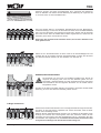
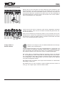
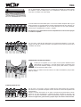
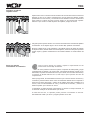
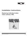
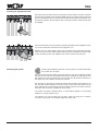
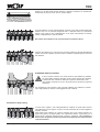
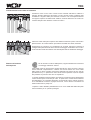
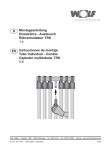
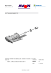
TRK
Technik, die dem Menschen dient.
D
Montageanleitung
Einzelröhre - Austausch
Röhrenkollektor TRK
1-4
ES Instrucciones de montaje
Tubo individual - Cambio
Captador multitubular TRK
5-8
GB Installation Instructions
Replacing individual tubes
Tube collector TRK
9-12
IT
Istruzioni per il montaggio
Sostituzione del singolo tubo
Collettore a tubi sottovuoto TRK
12-16
Wolf GmbH · Postfach 1380 · 84048 Mainburg · Tel. 08751/74-0 · Fax 08751/741600 · Internet: www.wolf-heiztechnik.de
3061285_1206
Art.-Nr.
30 61 285
Änderungen vorbehalten!
12/06 1
Servicehinweise
Defekte Röhren austauschen
TRK
Sicherheitshinweise
WARNUNG, STURZGEFAHR:
Bei der Arbeit auf dem Dach sowie beim Hinauf- und Hinabsteigen besteht Sturzgefahr. Beachten Sie unbedingt die Unfallverhütungsvorschriften und verwenden Sie
geeignete Absturzsicherungen.
WARNUNG, VERLETZUNGSGEFAHR:
Bei der Arbeit auf dem Dach besteht die Gefahr, dass Werkzeuge, Kollektorteile oder
Glassplitter vom Dach fallen und Personen verletzen, die sich darunter aufhalten.
Sperren Sie den Gefahrenbereich am Boden vor Beginn der Arbeit ab und warnen Sie
Personen, die sich in der Nähe oder im Gebäude aufhalten. Sorgen Sie dafür, dass
Kinder fern gehalten werden. Unbefugte Personen dürfen nicht auf das Dach steigen. Sammeln Sie, falls vorhanden, Glassplitter ein und lassen Sie sie nicht vom
Dach fallen.
WARNUNG, VERLETZUNGSGEFAHR:
Gefahr von Schnitt- und Augenverletzungen durch Glassplitter beim Entfernen beschädigter und dem Einsetzen neuer Röhren. Tragen Sie bei diesen Arbeiten Schutzhandschuhe und Schutzbrille.
VORSICHT, VERBRENNUNGSGEFAHR:
Wenn der Kollektor vor dem Röhrenaustausch direkter Sonneneinstrahlung ausgesetzt war, kann er sehr heiß sein. Verbrennungsgefahr beim Berühren! Führen Sie
den Austausch nur an einem bewölkten Tag und nicht während der Mittagszeit aus
oder decken sie den Kollektor mindestens eine Stunde vorher mit einer Decke ab,
damit er abkühlen kann.
Wer darf Röhren austauschen?
Der Austausch defekter Kollektorröhren darf nur von Personen ausgeführt werden,
die aufgrund ihrer beruflichen Qualifikation mit der Installation und sicheren Ausführung vertraut sind (Fachhandwerker).
Der Röhrenaustausch muss von zwei Personen ausgeführt werden.
Zugelassene Ersatzröhren
Verwenden Sie ausschließlich TRK-Original-Ersatzröhren von WOLF.
Versuchen Sie nicht, beschädigte Röhren zu reparieren, und verwenden Sie keine
anderen als Original-Ersatzröhren von WOLF. Nichtbeachtung kann zur Beschädigung der Anlage führen und gefährdet den Gewährleistungsanspruch.
Benötigtes Werkzeug
Zum Austausch von Kollektorröhren benötigen Sie ein weiches, sauberes Tuch, einen Schraubenzieher und jeweils einen Innen-Sechskantschlüssel SW 4 und SW 6.
Anlage drucklos schalten
Vor dem Austausch defekter Röhren muss der Solarkreis drucklos geschaltet werden. Gehen Sie dazu nach der Anleitung des Systems vor.
Die Anlage muss ausgeschaltet und gegen Wiedereinschalten gesichert werden.
Sie muss auch elektrisch außer Betrieb genommen werden und darf erst wider in
Betrieb gesetzt werden, wenn der Röhrenaustausch wie beschrieben abgeschlossen und eine neue Röhre eingesetzt ist.
Defekte Röhre entfernen
Packen Sie die Ersatzröhre aus, bevor Sie auf das Dach steigen, und nehmen Sie die
Röhre, alle mitgelieferten Teile, das mitgelieferte Fett sowie ein weiches Tuch (nicht
im Lieferumfang enthalten) mit auf das Dach.
Lösen Sie am defekten Kollektor zunächst mit einem Innen-Sechskantschlüssel SW
4 die beiden Schrauben unten an der Z-Schiene, ohne sie aber ganz herauszudrehen. Schieben Sie das dahinter liegende Halteblech, das die Kollektorröhren hält,
zum Dach hin weg, so dass die Röhren unten nicht mehr festgehalten werden.
2
3061285_1206
TRK
Entfernen Sie dann mit einem Schraubenzieher die 4 Schrauben der Abdeckung
oben am Kollektor und nehmen Sie die Abdeckung mit Dämmung ab. Legen Sie sie
so zur Seite, dass sie nicht hinabfallen kann.
Wenn die defekte Röhre in unmittelbarer Nachbarschaft einer der Befestigungsschrauben M8 liegt, so lösen Sie die Schraube mit einem Innen-Sechskantschlüssel
SW 6, da sonst die Röhre nicht entnommen werden kann. Drehen Sie die Schraube
aber nicht heraus. Wenn die defekte Röhre selbst angeschraubt ist, drehen Sie die
Schraube ganz heraus und entnehmen Sie sie.
Drehen Sie aber niemals beide Schrauben heraus, da sonst der Kollektor nicht
mehr gehalten wird!
Halten Sie nun die defekte Röhre mit einer Hand an der Kunststoffkappe fest und
schieben Sie mit der anderen Hand den Kunststoffschieber zur Seite, der die Röhre
am Sammler festhält. Nehmen Sie den Schieber vom Sammler ab.
WARNUNG, VERLETZUNGSGEFAHR
Da die Röhre nun nicht mehr vom Kollektor gehalten wird, könnte sie
aufgrund der Neigung nach unten aus dem Kollektor gleiten und vom
Dach fallen. Verletzungsgefahr für unten stehende Personen! Die Röhre
muss deshalb bei der nun folgenden Entnahme von der zweiten Person
festgehalten werden.
Drücken sie die Röhre mit beiden Händen vom Sammler. Verwenden Sie keinesfalls
Werkzeug, da sonst der Sammler beschädig werden könnte.
O-Ringe austauschen
Entfernen Sie mit der Hand oder dem Tuch vorsichtig die beiden O-Ringe am Sammleranschluss, an dem die Röhren aufgesteckt war. Achten Sie darauf, dass die Dichtflächen nicht beschädigt werden.
Reinigen Sie den Sammleranschluss mit dem Tuch. Schieben Sie die beiden neuen
O-Ringe auf: zunächst den schwarz-gelben, dann den schwarzen. Fetten Sie den
Anschluss und die O-Ringe mit dem mitgelieferten Fett ein. Verwenden Sie dazu
ausschließlich das mitgelieferte Fett. Verwenden Sie keinesfalls mineralisches Fett
und gehen sie unbedingt in der beschriebenen Reihenfolge vor!
3061285_1206
3
TRK
Neue Kollektorröhre einsetzen
Nehmen Sie nun die neue Röhre zur Hand. Stecken Sie das Koaxialrohr in den
Sammleranschluss und schieben Sie das Rohr anschließend auf den Sammler.
Achten Sie darauf, dass die Kunststoffteile sauber in den Nuten und Federn der
angrenzenden Teile laufen. Schieben Sie die Röhre oben und unten gleichzeitig auf
die Kollektorhalterungen. Achten Sie darauf, dass die Röhre nicht aus der Kollektorebene herausgehoben wird. Bruchgefahr!
Sichern sie das Rohr oben am Sammler, indem Sie den mitgelieferten Kunststoffschieber einschieben. Wenn sie eine der beiden Schrauben M8 gelöst haben, drehen Sie sie wieder ein.
Setzen Sie die Abdeckung mit Dämmung wieder auf und schrauben Sie sie fest.
Schieben Sie am Fußende das Halteblech hinter der Befestigungsschiene wieder zu
den Röhren hin, so dass sie gehalten werden, und drehen Sie die beiden Schrauben
unten an der Befestigungsschiene wieder fest.
Anlage wieder in
Betrieb nehmen
Beachten und befolgen Sie bei der Wiederinbetriebnahme die Montageanleitung des Gesamtsystems.
Vor der Wiederinbetriebnahme muss eine Dichtigkeitsprüfung vorgenommen und
müssen Kollektor und Solarkreis vollständig entlüftet werden. Handfüllpumpen sind
dazu nicht geeignet, eine Jetpumpe (min. 800 W, 40 m Förderhöhe) ist erforderlich.
Der Fülldruck soll dabei 0,5 bar über dem Druck im Ausgleichsgefäß liegen.
Die Pumpe sollte zur Vorentlüftung mindestens 30 Minuten laufen und mehrmals
ein- und ausgeschaltet werden. Dabei sollte der Wärmeträger über einen Kessel-,
Füll- und Entleerhahn (KFE-Hahn), eingebaut im Rücklauf zwischen Wärmetauscher
und Umwälzpumpe, in einen Behälter laufen und von dort wieder mit der Jetpumpe
ins System zurückgedrückt werden.
Die Anlage ist dann gut entlüftet, wenn längere Zeit keine Blasen im rücklaufenden
Wärmeträger sichtbar sind.
Der Kollektor kann nun, wenn er luftfrei ist, wieder in Betrieb genommen werden. Er
muss ggf. nach einigen Tagen nochmals entlüftet werden.
4
3061285_1206
TRK
Technik, die dem Menschen dient.
Instrucciones de montaje
Tubo individual - Cambio
Captador multitubular TRK
Wolf GmbH · Postfach 1380 · 84048 Mainburg · Tel. 08751/74-0 · Fax 08751/741600 · Internet: www.wolf-heiztechnik.de
3061285_1206
Con
reserva de modificaciones.
FR5
Instrucciones de servicio
Cambiar tubos defectuosos
TRK
Advertencias de seguridad
ADVERTENCIA, PELIGRO DE CAÍDA:
Cuando se trabaja en el tejado, y al subir y bajar del mismo, existe peligro de caída.
Respétese a rajatabla la normativa de prevención de accidentes y utilícense seguros
contra caídas adecuados.
ADVERTENCIA, PELIGRO DE LESIONES:
Cuando se trabaja en el tejado, existe peligro de que caigan herramientas, partes del
captador o esquirlas de vidrio y causen lesiones a personas situadas debajo. Acote la
zona de peligro en el suelo antes de comenzar los trabajos y advierta a las personas
que permanecen en los alrededores o dentro del edificio. Asegúrese de mantener
alejados a los niños. Las personas no autorizadas no deben subir al tejado. Recoja las
esquirlas de vidrio que puedan existir, evitando que caigan del tejado.
ADVERTENCIA, PELIGRO DE LESIONES:
Peligro de corte y de lesiones oculares por esquirlas de vidrio al desmontar tubos
dañados y montar tubos nuevos. Lleve guantes de protección y gafas de protección
durante los trabajos.
PRECAUCIÓN, PELIGRO DE QUEMADURAS:
El captador puede estar muy caliente si ha estado expuesto a la luz solar directa
antes de cambiar los tubos. ¡Peligro de quemaduras por contacto! Realice el cambio
sólo en días nublados, evitando las horas del mediodía, o cubra el captador con una
manta por lo menos una hora antes, para que pueda enfriarse.
¿Quién debe cambiar los tubos?
El cambio de los tubos de captador defectuosos se confiará exclusivamente a
profesionales cualificados que estén familiarizados con la instalación y ejecución
segura (instaladores especializados).
Para cambiar los tubos se requieren dos personas.
Tubos de recambio autorizados
Se utilizarán exclusivamente tubos de recambio originales TRK de WOLF.
No intente reparar tubos dañados y no utilice tubos que no sean recambios originales de WOLF. La inobservancia de lo señalado puede causar daños a la instalación
e invalidar la garantía.
Herramientas necesarias
Para cambiar los tubos del captador se necesita un paño suave limpio, un
destornillador y llaves Allen EC 4 y EC 6.
Despresurizar la instalación
Antes de cambiar los tubos averiados hay que quitar la presión del circuito solar.
Procédase según se especifica en las instrucciones del sistema.
La instalación ha de desconectarse y asegurarse contra toda nueva puesta en marcha.
Además deberá desconectarse también la parte eléctrica de la instalación, que no
se pondrá en marcha nuevamente hasta que se hayan cambiado los tubos y se haya
instalado un tubo nuevo.
Desmontar tubos defectuosos
Desembale el tubo de recambio antes de subir al tejado y lleve consigo el tubo, las
piezas suministradas, la grasa incluida y un paño suave (no incluido en el volumen
de suministro).
Con la llave Allen EC 4, afloje los dos tornillos del carril Z inferior del captador averiado,
sin desenroscarlos del todo. Empuje la chapa de sujeción trasera, que soporta los
tubos del captador, hacia el tejado para liberar la parte inferior de los tubos.
6
3061285_1206
TRK
Con un destornillador, desenrosque los 4 tornillos de la cubierta en la parte superior
del captador y quite la cubierta junto con el aislamiento. Colóquelos a un lado de
forma que no puedan caer hacia abajo.
Si el tubo defectuoso está situado junto a uno de los tornillos de fijación M8, hay que
aflojar el tornillo con una llave Allen EC 6 para poder desmontar el tubo. Atención: no
lo desenrosque completamente. Si es el tubo defectuoso el que está atornillado,
desenrosque completamente el tornillo y sáquelo.
No obstante, nunca deben desenroscarse completamente los dos tornillos porque
se soltaría el captador.
Con una mano, sujete el tubo defectuoso por el capuchón de plástico y, con la otra,
empuje a un lado la corredera de plástico que sujeta el tubo al colector. Desmonte la
corredera del colector.
ADVERTENCIA, PELIGRO DE LESIONES
Puesto que el captador ya no lo sujeta, el tubo podría deslizarse hacia
abajo debido a la inclinación y caer del tejado. Peligro de lesiones para
las personas situadas debajo. Por tanto, para poder sacarlo, es preciso
que otra persona sujete el tubo.
Saque el tubo con ambas manos del colector. No utilice herramientas, pues podrían
dañar el colector.
Cambiar juntas tóricas
Con la mano o con el paño, quite con cuidado las dos juntas tóricas de la conexión
del colector en la que estaba encajado el tubo. Atención a no dañar las superficies de
hermetización.
Limpie la conexión del colector con un paño. Coloque las dos juntas tóricas nuevas:
primero la de color amarillo/negro y después la negra. Engrase la conexión y las
juntas con la grasa suministrada. Utilice exclusivamente la grasa suministrada. No
utilice en ningún caso grasa mineral y respete al pie de la letra el orden descrito.
3061285_1206
7
TRK
Introducir el tubo de
captador nuevo
Sujete el tubo nuevo. Introduzca el tubo coaxial en la conexión del colector e introduzca
después el tubo en el colector. Asegúrese de que las piezas de plástico encajan
perfectamente en las ranuras y los resortes de los elementos vecinos. Introduzca la
parte superior e inferior del tubo al mismo tiempo en los soportes del captador.
Atención a que el tubo no salte del plano del captador. ¡Peligro de rotura!
Asegure la parte superior del tubo en el colector introduciendo la corredera de plástico
suministrada. Si ha aflojado alguno de los tornillos M8, apriételo nuevamente.
Monte la cubierta junto con el aislamiento y atorníllela. Empuje la chapa de sujeción
de la parte inferior, situada detrás del carril de fijación, hacia los tubos para que éstos
queden sujetos y apriete nuevamente los dos tornillos situados en el lado inferior del
carril.
Poner en marcha
nuevamente la instalación
Para la nueva puesta en marcha, respete lo especificado en las
instrucciones de montaje del sistema.
Antes de la nueva puesta en marcha es preciso comprobar la estanquidad y purgar
completamente el captador y el circuito solar. Las bombas de llenado manual no son
adecuadas; se precisa una bomba de chorro (mín. 800 W, 40 m de altura de bombeo).
La presión de llenado debería ser 0,5 bar mayor que la presión del vaso de
compensación.
Para la purga inicial, la bomba debería funcionar por lo menos durante 30 minutos y
conectarse y desconectarse varias veces. El termofluido debería fluir a un depósito a
través de una llave de llenado y vaciado de la caldera (llave KFE), instalada en el
retorno, entre el intercambiador de calor y la bomba de circulación, y retornar al
sistema impelido por la bomba de chorro.
La instalación se habrá purgado correctamente si, durante un tiempo suficiente, no
se observan burbujas en el termofluido que retorna.
Si está libre de aire, el captador puede ponerse nuevamente en marcha.
Eventualmente habrá que volver a purgarlo pasados unos días.
8
3061285_1206
TRK
Technik, die dem Menschen dient.
Installation Instructions
Replacing individual tubes
Tube collector TRK
Wolf GmbH · Postfach 1380 · 84048 Mainburg · Tel. 08751/74-0 · Fax 08751/741600 · Internet: www.wolf-heiztechnik.de
3061285_1206
Subject
to technical modifications.
GB9
Safety instructions
Removing faulty tubes
TRK
Safety instructions
WARNING, RISK OF A FALL:
There is a risk of a fall during work on the roof and whilst ascending/descending the
roof. Always observe all applicable accident prevention regulations and use suitable
methods for preventing a fall.
WARNING, RISK OF INJURY:
During the installation on the roof there is a risk that tools, collector parts or glass
splinters fall from the roof and injure people below. Seal off the danger area on the
ground prior to commencing your work and warn people that may be near or inside
the building. Ensure that children are kept away. Unauthorised individuals must not
ascend the roof. Collect, where required, all glass splinters and never let them fall
from the roof.
WARNING, RISK OF INJURY:
Risk of cuts and eye injuries through glass splinters during the removal of damaged
tubes and during their replacement. Always wear protective gloves and goggles during
this kind of operation.
CAUTION, RISK OF BURNING:
Collectors can be very hot if they were exposed to direct solar irradiation prior to the
tube replacement. There is a risk of burning when touching the collector. Only carry
out the replacement when it is overcast/cloudy and never during midday; alternatively
cover the collector with a blanket for at least one hour to allow it to cool down.
Who should replace the tubes?
Only individuals who are familiar with the installation and safe implementation
(contractor) on account of their vocational/professional qualification.
Two people are needed to replace the tubes.
Approved replacement tubes
Only use original TRK replacement tubes from WOLF.
Never attempt to repair faulty tubes and never use tubes other than original
replacement tubes from WOLF. Non-observation can result in system damage that
puts the manufacturer’s warranty at risk.
Required tools
The replacement of the collector tubes requires a soft clean cloth, a screwdriver and
respectively SW 4 and SW 6 Allen keys.
Put your system into an unpressurised state
Prior to replacing faulty tubes, the pressure in the solar circuit needs to be neutralised.
For this, proceed in accordance with the system instructions.
Disconnect the system from its power supply and prevent unauthorised reconnection.
Decommission the system electrically and only return it into use once the tube
replacement has been completed as described.
Removing the faulty tube
Unpack the replacement tube before climbing onto the roof and take the tube, all
components supplied with it and the grease supplied as well as a soft cloth (not part
of the standard delivery) with you onto the roof.
Initially, release both screws at the faulty collector at the bottom of the Z rail using a
SW4 Allen key, without fully removing the screws. Push the retaining plate below that
secures the collector tube, towards the roof so that the bottom of the tube is no longer
held in place.
10
3061285_1206
TRK
Then, remove the four screws from the cover at the top of the collector with a screwdriver,
and remove the cover with its insulation. Put it aside so it cannot fall.
If the faulty tube is immediately adjacent to a M8 fixing screw, undo the screw with a
SW6 Allen key, otherwise you cannot remove the tube. However, do not fully remove
the screw. Fully remove the screw if the faulty tube itself is secured by it.
However, never fully undo both screws, otherwise the tube would no longer be
held!
Now hold the faulty tube with one hand at the plastic cap and, with your free hand,
push the plastic slider aside that retains the tube at the header. Remove the slider
from the header.
WARNING, RISK OF INJURY
As the tube is no longer held by the collector, the slope of the roof could
lead to it sliding down out of the collector and falling off the roof. This
represents a risk for anyone below. Therefore, the tube must be held by
the second person during the following removal.
Push the tube with both hands off the header. Never use tools, otherwise the
header could be damaged.
Replacing the O-rings
Carefully by hand or with the cloth, remove both O-rings from the header connection,
where the tubes were plugged in. Ensure that the sealing faces are not damaged.
Clean the header connection with the cloth. Push on both new O-rings: first the blackyellow one, then the black one. Lubricate the connection and both O-rings with the
grease supplied. Only use the grease supplied. Under no circumstances use
mineral-based grease and never deviate from the sequence described here.
3061285_1206
11
TRK
Inserting the replacement tube
Now take up the new tube. Push the coaxial pipe into the header connection and push
the tube onto the header. Ensure that the plastic pieces run properly in the tongue and
groove of the adjacent parts. Push the tube simultaneously at the top and bottom onto
the collector retainers. Ensure that the tube is not lifted out of the collector level. Risk
of breakage.
Secure the tube at the top of the header by pushing the plastic slider supplied inwards.
If you have undone one of the M8 screws, retighten it now.
Replace the cover with insulation and secure it with the screws previously removed.
At the foot end, push the retaining plate behind the fixing rail towards the tubes again
so they are held in place; then retighten both screws at the bottom fixing rail.
Restarting the system
Observe the installation instruction for the system as a whole when taking
the system into use again.
Carry out a leak test before taking the system back into use, and completely ventilate
the collector and solar circuit. Manual fill pumps are unsuitable for this purpose; this
task requires a jet pump (at least 800 W, 40 m head). The fill pressure should be 0.5
bar higher than the expansion vessel inlet pressure.
Run the pump on pre-purge for at least 30 minutes and start/stop it several times. For
this, the heat transfer medium must flow through a fill & drain valve, fitted into the
return between the heat exchanger and the circulation pump into a container and from
there back into the system, propelled by the jet pump.
The system is properly ventilated when no more bubbles appear in the returning
medium for a longer period of time.
The collector can now be taken into use again, subject to being free of airlocks.
If required, it may need to be ventilated again after a few days.
12
3061285_1206
TRK
Technik, die dem Menschen dient.
Istruzioni per il montaggio
Sostituzione del singolo tubo
Collettore a tubi sottovuoto TRK
Wolf GmbH · Postfach 1380 · 84048 Mainburg · Tel. 08751/74-0 · Fax 08751/741600 · Internet: www.wolf-heiztechnik.de
Wolf Italia S.r.l. · Via 25 Aprile, 17 · 20097 S. Donato Milanese (MI) · Tel. 02-5161641 · Fax 02-515216 · Internet: www.wolfitalia.com
3061285_1206
Subject
to technical modifications.
IT13
Avvertenze per l‘assistenza
tecnica
Sostituzione dei tubi difettosi
TRK
Avvertenze per la sicurezza
ATTENZIONE, PERICOLO CADUTE:
Durante i lavori sul tetto come anche durante la salita e la discesa esiste il pericolo
di cadute. Attenersi scrupulosamente alle prescrizioni per evitare incidenti ed
utilizzare delle protezioni adattate con eventuali cadute.
ATTENZIONE, PERICOLO DI FERITE:
Durante i lavori sul tetto esiste il pericolo di caduta degli attrezzi, del materiale di
montaggio, dei collettori oppure delle scheggie di vetro, ferendo in questo modo le
persone che si trovano in basso. Chiudere la zona di pericolo prima di iniziare i
lavori ed avvertire le persone che si trovano nelle vicinanze oppure in casa. Tenere
lontano i bambini. Persone non autorizzate non devono salire sul tetto. Raccogliere
se necessario eventuali scheggie di vetro e non fare cadere nulla dal tetto.
ATTENZIONE, PERICOLO DI FERITE:
Pericolo di ferite di taglio oppure degli occhi per scheggie di vetro durante la
sostituzione di nuovi tubi. Durante questi lavori portare sempre dei guanti protettivi
e degli occhiali di protezione.
ATTENZIONE, PERICOLO DI SCOTTATURE:
Con l‘irraggiamento solare diretto il collettore può raggiungere temperature molto
alte. Esiste il pericolo di scottature in caso di contatto! Eseguire il montaggio sul
tetto solo in una giornata nuvolosa e non durante le ore più calde oppure coprire il
collettore con una coperta.
Chi è autorizzato ad eseguire il montaggio dei collettori?
La progettazione del montaggio, il montaggio sul tetto e la messa in funzione del
collettore a tubi sottovuoto deve essere eseguita solo da persone in possesso dei
requisiti tecnici per quanto riguarda l‘installazione e l‘esecuzione dell‘impianto a
regola d‘arte ed in modo sicuro (tecnico specializzato ed autorizzato).
Per effettuare il montaggio sul tetto sono necessarie due persone.
Tubi di sostituzione idonei
Utilizzare esclusivamente tubi TRK originali WOLF per la sostituzione.
Non cercare di riparare dei tubi difettosi ed utilizzare sempre tubi originali WOLF.
La innosservanza di quanto sopra può portare a danneggiamenti sull‘impianto ed
influisce sulla garanzia.
Attrezzi/materiali necessari
Per la sostituzione dei tubi collettori sono necessari un panno morbido, pulito, un
cacciavite e sempre una chiave esagonale SW 4 e SW 6.
Togliere la pressione dell‘impianto
Prima della sostituzione dei tubi difettosi, togliere la pressione dal circuito solare
procedendo in base alle istruzioni del sistema.
L‘impianto deve essere spento e deve essere assicurato contro una eventuale
riaccensione. Deve essere messa fuori funzione anche la parte elettrica e può
essere rimessa in servizio dopo aver terminato la sostituzione dei tubi come
descritto e dopo aver inserito il tubo nuovo.
Togliere il tubo difettoso
Prima di salire sul tetto, togliere il tubo di sostituzione dal suo imballo e portare sul
tetto il tubo stesso, tutti i pezzi ed il grasso forniti ed un panno morbido (non in
dotazione).
Allentare inizialmente le due viti sul binario inferiore del collettore difettoso utilizzando
una chiave esagonale SW 4 senza svitarle completamente. Spingere la lamiera di
sostegno posizionata sul retro, che serve come supporto dei tubi collettore, verso il
tetto, in modo che i tubi non possano più essere tenuti in basso.
14
3061285_1206
TRK
Svitare le 4 viti dalla parte alta del collettore e togliere la copertura con l‘isolamento.
Posizionarla in parte in modo che non possa cadere.
Se il tubo difettoso si trova nelle immediate vicinanze di una delle viti di fissaggio M8,
svitare la vite con un cacciavite esagonale SW 6, altrimenti il tubo non può essere
estratto. Non svitare la vite completamente. Se lo stesso tubo difettoso è avvitato,
svitare completamente la vite ed estrarla.
Non svitare mai entrambe le viti, in questo modo il collettore è libero!
Tenere il tubo difettoso con una mano sul raccordo in plastica e spingere lateralmente
il pezzo scorrevole in plastica che fissa il tubo al collettore. Togliere il pezzo scorrevole
dal collettore.
ATTENZIONE, PERICOLO DI FERITE
Il tubo in questo momento non viene più tenuto dal collettore e potrebbe
per causa della pendenza scivolare verso la parte inferiore del collettore
e cadere dal tetto. Pericolo di ferite per le persone sottostanti! Il tubo
deve essere quindi tenuto da una seconda persona durante la seguente
estrazione.
Con entrambe le mani premere il tubo fuori dal collettore. Non utilizzare in nessun
caso degli attrezzi per evitare il danneggiamento del collettore.
Sostituzione degli O-Ring
In modo cauto, togliere i due O-Ring dall‘attacco collettore sul quale erano inseriti i
tubi utilizzando le mani oppure un panno facendo attenzione di non danneggiare le
superfici di tenuta.
Pulire l‘attacco del collettore con il panno. Spingere i due nuovi O-Ring, iniziando con
quello nero-giallo e di seguito quello nero. Ingrassare l‘attacco e gli O-Ring con il
grasso fornito. Utilizzare esclusivamento il grasso in dotazione. Non utilizzare in
nessun caso del grasso minerale e procedere assolutamente nell‘ordine descritto
in queste istruzioni!
3061285_1206
15
TRK
Inserimento del nuovo tubo sul collettore
Prendere il mano il nuovo tubo. Inserire il tubo coassiale nell‘attacco collettore e
spingere facendo attenzione ad inserire in modo corretto le parti in plastica nelle
scanalature e linguette delle parti adiacenti. Inserire il tubo contemporaneamente
nei supporti superiore ed inferiore del collettore, facendo attenzione che il tubo non
fuoriesca dal piano del collettore. Pericolo di rottura !
Assicurare il tubo sulla parte superiore del collettore inserendo il pezzo scorrevole in
plastica fornito. Se è stata svitata in precedenza una delle due viti M8, riavvitarla.
Riappoggiare la copertura con l‘isolamento ed avvitarla. Spingere la lamiera di
sostegno sulla parte terminale dietro il binario di fissaggio nuovamente verso i tubi in
modo che sia a tenuta ed avvitare le due viti sulla parte inferiore del binario di fissaggio.
Rimessa in funzione
dell‘impianto
Per la rimessa in funzione dell‘impianto, seguire attentamente le istruzioni
di montaggio dell‘intero sistema.
Prima della messa in funzione deve essere eseguita una prova di tenuta e devono
essere disaerati completamente i collettori ed il circuito solare. Non sono adatte
delle pompe a carica manuale. Deve essere utilizzata una pompa Jet (min. 800 W,
prevalenza 40 m). La pressione di carica deve essere superiore di 0,5 bar rispetto
alla pressione di precarica del vaso di espansione.
La pompa dovrebbe funzionare almeno 30 minuti per consentire una pre-disaerazione
e deve essere spenta e riaccesa più volte. In questa fase il fluido termoconduttore
dovrebbe fluire in un contenitore attraverso un rubinetto di scarico, inserito nel ritorno
tra lo scambiatore di calore e la pompa di ricircolo, e da lì caricato nuovamente nel
sistema attraverso la pompa Jet.
L‘impianto è stato disaerato perfettamente se non sono visibili delle bolle nel liquido
termoconduttore per un periodo prolungato.
16
3061285_1206