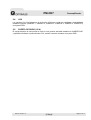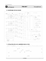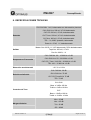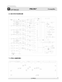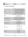
1
PREAMPLIFICADOR
PREAMPLIFIER
PM-CH7
Manual de instalación y funcionamiento v1.0
Installation and operating instructions v1.0
PM-CH7
Preamplificador
INSTRUCCIONES DE SEGURIDAD:
IMPORTANTE:
Los códigos de color de los cables de red son los siguientes:
Verde y amarillo
Tierra
(E)
Azul
Neutro
(N)
Marrón
Positivo
(L)
Si los colores de los cables de red de este aparato no se corresponden con las marcas de
sus terminales de conexión, debe procederse como sigue:
Conectar el cable de color verde y amarillo al terminal marcado con la letra E o con el
símbolo de tierra. Conectar el cable de color azul al terminal negro o marcado con la letra N.
Conectar el cable de color marrón al terminal rojo o marcado con la letra L.
Si se usa un conector macho de 13 A (BS1363), o de cualquier otro tipo, debe colocarse un
fusible de 5 A en el conector o en la caja de distribución.
INSTALACIÓN GENERAL
NO PASAR los cables de micrófono cerca de cables telefónicos, de datos o de línea de 100 V.
NO PASAR los cables de línea de 100 V cerca telefónicos, de datos o de baja tensión.
NO SOBREPASAR el 90% de la potencia de salida de los amplificadores cuando se utiliza la
línea de 100 V para avisos.
NO SOBREPASAR el 70% de la potencia de salida de los amplificadores cuando se utiliza la
línea de 100 V para música ambiental a alto volumen.
NO UTILIZAR altavoces exponenciales para música ambiental, excepto si éstos han sido
especialmente diseñados para esta función.
EVITAR empalmes en los cables de micrófono. Si es inevitable, utilizar exclusivamente
conectores blindados de buena calidad, como los XLR.
Utilizar SIEMPRE para distancias largas, micrófonos balanceados de baja impedancia o
aislados de la masa conectados a entradas balanceadas.
Utilizar SIEMPRE un cable doble aislante de calidad equivalente a los de la red de baja
tensión para las conexiones de los altavoces.
ASEGURARSE de que todos los altavoces estén en fase.
ASEGURARSE de que no existe ningún cortocircuito en la línea de altavoces antes de
conectarla al amplificador.
PM-CH7 Versión 1.0
Página 1 de 12
PM-CH7
Preamplificador
ÍNDICE
1.
DESCRIPCIÓN ........................................................................................................ 3
2.
PANEL FRONTAL ................................................................................................... 4
3.
PANEL POSTERIOR ............................................................................................... 4
4.
CONEXIONES Y FUNCIONAMIENTO .................................................................... 5
5.
4.1.
ENTRADA TEL / EMER (1) .......................................................................................... 5
4.2.
ENTRADA CH1 (3) ....................................................................................................... 5
4.3.
ENTRADAS CH2-CH6 (6 y 7) ...................................................................................... 5
4.4.
ENTRADAS CH7 .......................................................................................................... 5
4.4.1.
ENTRADA CD (9) ...............................................................................................................5
4.4.2.
ENTRADAS AUX / TUNER (10 y 11).................................................................................5
4.5.
SALIDA PRE OUT / ENTRADA POWER IN (12)......................................................... 5
4.6.
SALIDA TAPE OUT (14) .............................................................................................. 6
4.7.
SALIDA MASTER OUT (15 y 16) ................................................................................ 6
4.8.
CONECTOR DIN MASTER / SLAVE (17).................................................................... 6
4.9.
CONEXIÓN DE GND Y CHASIS (19) .......................................................................... 6
4.10.
OVERRIDE (20)............................................................................................................ 6
4.11.
CONEXIÓN DE ALIMENTACIÓN 24 VCC (21) ........................................................... 6
4.12.
CONEXIÓN BATERIA 24 VCC (22) ............................................................................. 6
4.13.
INTERRUPTOR POWER ON / OFF (1)........................................................................ 6
4.14.
VUMETRO DE SALIDA (3) .......................................................................................... 6
CONFIGURACIÓN .................................................................................................. 7
5.1.
PRIORIDAD.................................................................................................................. 7
5.2.
DIP SWITCH DE CONFIGURACIÓN CH1-CH6 (5) ..................................................... 7
5.2.1.
PARÁMETROS ESPECÍFICOS PARA EL CH1 ................................................................7
5.2.2.
PARÁMETROS PARA CANALES CH1-CH6 ....................................................................7
5.3.
FILTRO DE PALABRA ................................................................................................ 7
5.4.
VOX .............................................................................................................................. 8
5.5.
PUERTA DE RUIDO (VCA).......................................................................................... 8
6.
DIAGRAMA DE BLOQUES..................................................................................... 9
7.
SITUACION DE LOS JUMPERS EN EL PCB......................................................... 9
8.
ESPECIFICACIONES TÉCNICAS......................................................................... 10
9.
CERTIFICADO DE GARANTÍA............................................................................. 12
PM-CH7 Versión 1.0
Página 2 de 12
PM-CH7
Preamplificador
1. DESCRIPCIÓN
Preamplificador mezclador de 1 unidad de rack estándar de 19”.
Dispone de 7 canales de entrada con ajustes de volumen y tono independientes.
Canal 1-6 con sensibilidad Micro / Línea ajustable.
Prioridad por VOX o contacto seleccionable para el canal 1.
Gong seleccionable para el canal 1 con nivel ajustable.
Filtro de palabra seleccionable para mejora de inteligibilidad de palabra.
Canal 7 para selección entre 3 entradas para fuentes musicales, CD, AUX o TUNER.
Entrada TEL/ EMER con prioridad por VOX para avisos de emergencia.
Potenciómetro Master para ajustar el nivel de salida general de la unidad.
Conectores RCA con salida de señal no balanceada para PRE OUT, TAPE OUT y MASTER
OUT.
Conector XLR con salida de señal balanceada para MASTER OUT.
Conector MASTER / SLAVE para expandir el sistema a 2 unidades ampliando el número de
canales de 7 a 14.
PM-CH7 Versión 1.0
Página 3 de 12
PM-CH7
Preamplificador
2. PANEL FRONTAL
(1) Interruptor de encendido ON/OFF
(6) Controles de tono CH1-CH6
(2) LED de alimentación
(7) Selector de fuente musical
(3) VUMETRO de salida
(8) LED indicador de fuente musical
(4) Control de volumen MASTER
(9) Control de Graves y agudos CH7
(5) Controles de nivel de entrada CH1-CH6
(10) Control de Nivel de entrada CH7
3. PANEL POSTERIOR
(1)
Entrada TEL/EMER
(12) Salida PRE OUT
(2)
Control de nivel TEL/EMER
(13) Entrada POWER IN
(3)
Entrada CH1
(14) Salida TAPE OUT
(4)
Control de nivel del Gong de entrada CH1 (15) Salida no balanceada MASTER OUT
(5)
Dipswitch CH1 y CH2
(16) Salida balanceada MASTER OUT
(6)
Entrada XLR del CH2
(17) Conector DIN MASTER / SLAVE
(7)
Entrada XLR del CH3-CH6
(18) Interruptor MASTER /SLAVE
(8)
Dipswitch del CH3-CH6
(19) Unión GND y chasis
(9)
Entrada de CD
(20) Override
(10) Entrada auxiliar
(21) Entrada de alimentación 24 Vcc
(11) Entrada Tuner
(22) Entrada de alimentación para batería 24 Vcc
PM-CH7 Versión 1.0
Página 4 de 12
PM-CH7
Preamplificador
4. CONEXIONES Y FUNCIONAMIENTO
4.1.
ENTRADA TEL / EMER (1)
Entrada balanceada con prioridad por VOX. Prioridad máxima respecto al resto de entradas.
Control de volumen independiente ubicado en el panel posterior. El nivel de señal de esta
entrada no se ve afectado por la regulación del control de volumen MASTER. Umbral de
activación del VOX controlable mediante potenciómetro VR3 de la placa interna.
4.2.
ENTRADA CH1 (3)
Entrada balanceada con sensibilidad Micro / Línea seleccionable. Dispone de prioridad
configurable por VOX o por contacto. Conexión mediante 3 terminales en la regleta de entrada
de señal correspondientes a (GND / + / -) para la conexión del audio balanceado y dos
terminales de contacto para activar la función de prioridad. Gong de preaviso configurable
activado desde el contacto de prioridad.
4.3.
ENTRADAS CH2-CH6 (6 y 7)
Entradas balanceadas mediante conectores XLR, con sensibilidad Micro / Línea y alimentación
phantom seleccionable.
4.4.
ENTRADAS CH7
El canal 7 dispone de 3 entradas para fuente musical, con un control volumen, graves y
agudos general. La entrada asignada al canal se selecciona desde el pulsador SELECTOR en
el panel frontal.
4.4.1. ENTRADA CD (9)
Entrada no balanceada de 500 mV mediante dos conectores RCA indicada para introducir una
señal procedente de una fuente musical.
4.4.2. ENTRADAS AUX / TUNER (10 y 11)
Entradas no balanceadas de 200 mV mediante dos
conectores RCA indicadas para introducir una señal
procedente de una fuente musical.
4.5. SALIDA PRE OUT / ENTRADA POWER IN (12)
Entrada / Salida de sensibilidad 1 V utilizada para intercalar equipos externos (ecualizador,
supresor de Efecto Larsen…).
Salida PRE-OUT mediante conector RCA, señal preamplificada controlada por el master.
Entrada POWER IN mediante conector RCA.
PM-CH7 Versión 1.0
Página 5 de 12
PM-CH7
Preamplificador
En caso de no usar esta funcionalidad, el puente de interconexión entre PRE-OUT y POWER
IN debe estar colocado.
4.6.
SALIDA TAPE OUT (14)
Señal de salida para grabación no controlada por el Master. Conexión mediante conectores
RCA a nivel de 350 mV.
4.7.
SALIDA MASTER OUT (15 y 16)
Salida general a nivel de 1 V. Está controlada por el volumen Master y dispone de doble
conexión, balanceada mediante conector XLR (16) y no balaceada (15) mediante dos
conectores RCA.
4.8.
CONECTOR DIN MASTER / SLAVE (17)
Conector de expansión para interconectar 2 unidades.
Al interconectar 2 unidades se obtendrán 14 canales con 14 niveles de prioridad distintos,
siendo las entradas de la unidad master más prioritarias que la unidad SLAVE.
La máxima prioridad disponible para la unidad SLAVE es equivalente a la fuente musical de la
unidad MASTER, motivo por el cual se recomienda que si se utilizan fuentes musicales, se
conecten siempre a la unidad SLAVE.
4.9.
CONEXIÓN DE GND Y CHASIS (19)
Para evitar ruidos provocados por bucles de masa es muy importante que haya un solo punto
de unión entre la masa de señal y el contacto de tierra de la red. Si la instalación de megafonía
está compuesta por varios equipos, probablemente tendrán los chasis unidos, bien mediante
el terminal de tierra de la conexión a la red, o bien porque estén montados en un armario rack.
Si las masas están también unidas por los circuitos de señal, es aconsejable quitar el puente
entre la masa y el chasis de todos los aparatos excepto uno.
4.10. OVERRIDE (20)
Contacto libre de tensión que se cierra al activarse la prioridad de la entrada TEL / EMER.
4.11. CONEXIÓN DE ALIMENTACIÓN 24 VCC (21)
Terminales de conexión de alimentación 24 Vcc.
4.12. CONEXIÓN BATERIA 24 VCC (22)
Terminales de conexión para alimentación mediante batería de 24 Vcc.
4.13. INTERRUPTOR POWER ON / OFF (1)
Pulse el interruptor para encender o apagar la unidad, el encendido de la unidad se indicará
mediante el encendido del LED de alimentación.
En un sistema de megafonía, el preamplificador siempre debe ser el primer equipo a
encenderse y el último a apagarse.
4.14. VUMETRO DE SALIDA (3)
Una barra de 5 LEDs indica el nivel de señal de salida del amplificador, si el LED rojo se
enciende, disminuya el nivel de salida mediante los potenciómetros de volumen de las señales
entrantes.
PM-CH7 Versión 1.0
Página 6 de 12
PM-CH7
Preamplificador
5. CONFIGURACIÓN
5.1.
PRIORIDAD
La configuración de las prioridades del sistema viene definida por de la posición de los Jumper
internos SW9, SW10 y SW11.
El equipo dispone de tres niveles de prioridad diferentes; Block before, Block behind y Serial.
Modo Serial: Las prioridades quedan definidas según el número de canal. Siendo CH1 el
canal de prioridad máxima y CH7 el de prioridad mínima (CH1 > CH2 > CH3 > CH4 > CH5
> CH6 > CH7).
Modo Block before: De los canales CH1, CH2, CH3, CH4, CH5 y CH6, el primero en
activarse tendrá la máxima prioridad y bloqueará el resto de canales incluido el CH7 que
no tiene prioridad.
Modo Block behind: De los canales CH1, CH2, CH3, CH4, CH5 y CH6, el último en
activarse tendrá máxima prioridad y bloqueará el resto de canales, incluido el CH7 que no
tiene prioridad.
5.2.
DIP SWITCH DE CONFIGURACIÓN CH1-CH6 (5)
Mediante los dipswich del panel posterior se permite la modificación de una serie de
parámetros.
5.2.1. PARÁMETROS ESPECÍFICOS PARA EL CH1
Chime / Off: en posición Chime el equipo reproducirá un gong de preaviso al activarse la
prioridad del canal 1.
Se puede regular el volumen del gong mediante el potenciómetro situado en la parte
trasera del equipo (4).
PTT / Off: En posición PTT, la señal de audio de la entrada 1 no se enviara a la salida si no
se cierra el contacto de prioridad entre los terminales de la regleta.
En posición Off no es necesario el contacto de la regleta para enviar el audio a la salida.
En ambos caso al cerrar el contacto de prioridad se silenciaran el resto de canales.
5.2.2. PARÁMETROS PARA CANALES CH1-CH6
Line / Mic: Selección de la sensibilidad entre -60 dB (MIC) o 0 dB (LINE).
Phantom / Off: Permite habilitar o deshabilitar la alimentación phantom. Este microinterruptor
gobierna dos canales, por lo que se recomienda tener especial cuidado al activar esta función.
La alimentación phantom debe deshabilitarse en el modo Line.
5.3.
FILTRO DE PALABRA
Los canales CH1-CH6 disponen de un filtro de palabra que puede ser habilitado o
deshabilitado mediante jumpers (SW1, SW2, SW3, SW4, SW5, SW6) de la placa PCB. El filtro
de palabra mejora la inteligibilidad de palabra mediante el recorte de las frecuencias más
bajas.
PM-CH7 Versión 1.0
Página 7 de 12
PM-CH7
5.4.
Preamplificador
VOX
Los canales CH1-CH6 disponen de la función VOX que puede ser habilitada o deshabilitada
mediante jumpers (JUMPER 1, JUMPER 2, JUMPER 3, JUMPER 4, JUMPER 5, JUMPER 6)
de la placa PCB.
5.5.
PUERTA DE RUIDO (VCA)
El equipo dispone de una puerta de ruido a nivel general activable mediante el JUMPER SW7
y ajustable mediante el potenciómetro P19, ambos controles situados en la placa PCB.
PM-CH7 Versión 1.0
Página 8 de 12
PM-CH7
Preamplificador
6. DIAGRAMA DE BLOQUES
7. SITUACION DE LOS JUMPERS EN EL PCB
PM-CH7 Versión 1.0
Página 9 de 12
PM-CH7
Preamplificador
8. ESPECIFICACIONES TÉCNICAS
CH1-CH6 Mic: 1 mV, balanceada con alimentación phantom
CH1-CH6 Line: 200 mV, 47 kΩ balanceada
CH7 CD: 500 mV, 47 kΩ, desbalanceada
Entradas
CH7 Tuner: 200 mV, 47 kΩ, desbalanceada
CH7 Aux: 200 mV, 47 kΩ, desbalanceada
TEL: 1 V, 600Ω, ajustable, balanceada
Power In: 47 kΩ, 1 V, desbalanceada
Master Out: 600 Ω, 1V, XLR balanceada, RCA desbalanceada
Salidas
Tape Out: 350 mV, 4.7 kΩ
Pre Out: 600 Ω, 1 V
CH1-CH6 Mic: 60 ~ 15.000 Hz ± 3 dB
Respuesta en Frecuencia
CH1-CH6 Line: 50 ~ 20.000Hz ± 3 dB
CH7 CD / Tuner / AUX 50 ~ 20.000 Hz ± 3 dB
TEL: 100 ~ 15.000 Hz ± 3 dB
Distorsión armónica total
< 0.5 % a 1 KHz
CH1-CH6 Mic: 60 dB
Relación señal/ruido
CH1-CH6 Line: 75 dB
CH7 CD /Tuner/AUX: 75 dB
TEL: 75 dB
CH1-CH6
Bass: ± 3 dB a 300 Hz
Controles de Tono
Treble: ± 3 dB a 10 KHz
CH7
Bass: ± 10 dB a 100 Hz
Treble: ± 10 dB a 10 kHz
Mic > 25 dB
Margen dinámico
Line > 25 dB
Tel > 20 dB
CD > 25dB
PM-CH7 Versión 1.0
Página 10 de 12
PM-CH7
Preamplificador
AUX > 25 dB
Tuner > 25 dB
Filtro de palabra
CH1-CH6: -3.5 dB a 315 Hz
Alimentador
24 Vcc (Máx 10% de desviación)
Batería
24 Vcc (Máx 10% de desviación)
Alimentación
Consumo
Dimensiones (mm)
1A
438 x 222 x 44
peso
2.85 kg
color
Negro
Unidades de Rack
PM-CH7 Versión 1.0
1
Página 11 de 12
PM-CH7
Preamplificador
9. CERTIFICADO DE GARANTÍA
7. En el caso de ordenadores PC, la garantía no cubrirá la eliminación de virus
informáticos, restauración de programas por este motivo o la reinstalación del
disco provocada por el borrado del mismo.
1. La empresa OPTIMUS S.A. garantiza que sus productos se encuentran
libres de defectos en materiales y de mano de obra en el momento de su
entrega original al comprador.
8. Los derechos de garantía se anulan si el producto ha sido reparado o
abierto por un personal no autorizado OPTIMUS S.A. o por el propio cliente.
2. La empresa OPTIMUS S.A. concede a sus productos, conforme a las
condiciones aquí descritas, una garantía de dos (2) años a partir de la fecha de
adquisición del producto por el comprador. Si, dentro de este plazo de
garantía, se producen defectos que no sean debidos a razones mencionadas
bajo el punto 2, la empresa OPTIMUS S.A. remplazará o reparará el aparato
utilizando piezas de recambio equivalentes, nuevas o reconstruidas, según
criterio propio. Si se aplican piezas de recambio que constituyen una mejora
del aparato, la empresa OPTIMUS S.A. se reserva el derecho de cargar el
coste adicional de estos componentes al cliente.
3. No se concederán prestaciones de garantía distintas a las citadas.
4. Para la utilización de los derechos de garantía será requisito indispensable
presentar la factura de compra original o el certificado de garantía.
2. DISPOSICIONES DE GARANTÍA
1. Si el producto tuviera que ser modificado o adaptado para cumplir con los
requisitos locales en cuanto a técnica o seguridad, si no se trata del país para
el cual el producto fue concebido y fabricado originalmente, ello no se
considera como defecto de material o de fabricación. Por lo demás, la garantía
no comprende la realización de estas modificaciones o adaptaciones,
independientemente de si éstas hayan sido ejecutadas debidamente o no.
OPTIMUS S.A. tampoco asumirá costes en el marco de la garantía por este
tipo de modificaciones.
2. La garantía no dará derecho a inspección o mantenimiento gratuito o
reparación del aparato, particularmente si los defectos son debidos a uso
inapropiado. Los derechos de garantía tampoco abarcan defectos en piezas de
desgaste que sean debidos a un desgaste normal. Piezas de desgaste son, en
particular, potenciómetros, interruptores/teclas, y piezas similares.
3. La garantía no abarca los defectos en el equipo causados por:
¾
¾
¾
¾
¾
¾
¾
¾
Abuso o uso incorrecto del aparato para fines distintos a los previstos,
en incumplimiento de las instrucciones de servicio y de mantenimiento
especificadas en el Manual y/o Instrucciones Técnicas del equipo.
Conexión o uso del producto de una manera que no corresponda a los
requisitos técnicos o de seguridad del país en el cual se utiliza el
aparato.
Instalación en condiciones distintas a los indicados en el Manual y/o
Instrucciones Técnicas.
Deficiencia o interrupciones tensión eléctrica o defectos de instalación
que impliquen uso en condiciones anormales.
Daños ocasionados por otros equipos interconectados al producto.
El uso o instalación de Software (programas), interfaces, partes o
suministros no proporcionados y/o autorizados por OPTIMUS S.A.
La no utilización de los embalajes originales para su transporte.
Daños causados por fuerza mayor u otras causas no imputables a
OPTIMUS S.A.
4. No están cubiertos por esta garantía los siguientes elementos:
¾
¾
¾
¾
Todas las superficies de plástico y todas las piezas expuestas al exterior
que hayan sido rayadas o dañadas debido al uso normal o anormal.
Las roturas, golpes, daños por caídas o ralladuras causadas por
traslados de cualquier naturaleza.
Defectos de daños derivados de pruebas, uso, mantenimiento,
instalación y ajustes inapropiados, o derivados de cualquier alteración o
modificación de cualquier tipo no realizada por en Servicio Autorizado
por OPTIMUS S.A. en cumplimiento de esta garantía.
Los daños personales o a la propiedad que pudieran causar el uso
indebido del equipo, incluyendo la falta de mantenimiento.
5. La garantía carecerá de validez cuando se observe:
¾
¾
¾
Enmiendas o tachaduras en los datos del certificado de garantía o
factura de compra.
Falta de factura original o falta de fecha en la misma.
Falta de número de serie o lote en el equipo.
9. Si la empresa OPTIMUS S.A. estableciera al comprador del aparato que los
daños presentados no dan derecho a la reclamación de la garantía, los costes
de las prestaciones de revisión por parte de la empresa OPTIMUS S.A.
correrán a cargo del cliente.
10. Los productos sin derechos de garantía sólo se repararán contra pago de
los gastos por el cliente. En caso de ausencia de derechos de garantía,
OPTIMUS S.A. informará al cliente al respecto. Si, en un plazo de 6 semanas
a partir de esta comunicación, no recibimos ninguna orden de reparación
escrita confirmando la aceptación de los gastos, OPTIMUS S.A. devolverá el
aparato en cuestión al cliente. En este caso, los gastos de transporte y
embalaje se facturarán por separado y se cobrarán contra reembolso. En caso
de expedición de una orden de reparación, confirmando la asunción de los
gastos, los gastos de transporte y de embalaje se facturarán adicionalmente,
igualmente por separado.
11. En caso de necesidad de traslado al Centro de Servicio Autorizado, el
transporte será realizado por el responsable de la garantía, y serán a su cargo
los gastos de flete y seguro.
12. En caso de falla, OPTIMUS S.A. asegura al comprador la reparación y/o
reposición de partes para su correcto funcionamiento en un plazo no mayor a
30 días. No obstante, se deja aclarado que el plazo usual no supera los 30
días.
13. Todas las piezas o productos sustituidos al amparo de los servicios en
garantía pasarán a ser propiedad de OPTIMUS S.A.
3. TRANSFERENCIA DE LA GARANTÍA
La garantía se concede únicamente para el comprador original (cliente
principal) y es intransferible. Con excepción de la empresa OPTIMUS S.A.,
ningún tercero (comerciantes, etc.) está autorizado a conceder garantía
adicionales en nombre de la empresa OPTIMUS S.A.
4. RECLAMACIONES POR DAÑOS Y PERJUICIOS
En caso de que OPTIMUS S.A. no pueda proporcionar un servicio de garantía
adecuado, el comprador no tendrá ningún derecho a reclamar indemnización
alguna por daños y perjuicios consecuentes. La responsabilidad de la empresa
OPTIMUS S.A. se limita en todo caso al precio de facturación del producto
5. RELACIÓN CON OTROS DERECHOS DE GARANTÍA Y CON EL
DERECHO NACIONAL
1. Mediante esta garantía no se afecta a los derechos del comprador frente al
vendedor deducidos del contrato de compraventa concluido.
2. Las presentes condiciones de garantía de la empresa OPTIMUS S.A. son
válidas siempre que no contradigan el derecho nacional correspondiente en
relación con las disposiciones de garantía.
3. OPTIMUS S.A. asegura que este producto cumple con las normas de
seguridad vigentes en el país.
ESTA DECLARACIÓN DE GARANTÍA LIMITADA ES LA GARANTÍA
EXCLUSIVA OFRECIDA POR OPTIMUS S.A. SE EXCLUYE TODA OTRA
GARANTÍA EXPLÍCITA O IMPLÍCITA, INCLUIDAS LAS GARANTÍAS DE
COMERCIALIDAD Y APTITUD A UN FIN DETERMINADO. (EXCEPTO
CUANDO DICHAS GARANTÍAS SEAN REQUERIDAS POR UNA LEY
APLICABLE). NINGUNA GARANTÍA, YA SEA EXPLÍCITA O IMPLÍCITA, SE
APLICARÁ TRAS LA FINALIZACIÓN DEL PERIODO DE GARANTÍA.
OPTIMUS S.A.
Servicio Post Venta
C/ Barcelona 101
17003 - GIRONA
Tel. 902 151 96 / 972 203 300
Fax. 972 21 84 13
e-mail : [email protected] 1999/44/CE
6. La garantía no cubre los desplazamientos por asistencias técnicas a
excepción de los motivados por incidencias ocurridas durante los tres primeros
meses.
PM-CH7 Versión 1.0
Página 12 de 12
PM-CH7
Preamplifier
SAFETY INSTRUCTIONS:
IMPORTANT:
The wires in the mains lead are coloured in accordance with the following code:
Green and Yellow
Earth
(E)
Blue
Neutral
(N)
Brown
Live
(L)
If the colours of the wires in the mains lead of this apparatus do not correspond with the
colour markings identifying the terminals in your plug, proceed as follows:
The wire which is coloured green and yellow must be connected to the terminal which is
marked by the letter E, or by the safety earth symbol or coloured green and yellow. The wire
which is coloured blue must be connected to the terminal which is marked with the letter N or
coloured black. The wire which is coloured brown must be connected to the terminal which is
marked with the letter L or coloured red.
If a 13 A (B.S.1363) plug or any other type of plug is used, a 5 A fuse must be fitted either in
the plug or at the distribution board.
GENERAL INSTALLATION
DO NOT run microphone cables near mains, data, telephone or 100V line cables.
DO NOT run 100V line cables near data, telephone or other low voltage cables.
DO NOT exceed 90% of the amplifier’s output power when using 100V line (speech only).
DO NOT exceed 70% of the amplifier’s output power when using 100V line (high level
background music).
DO NOT use horn loudspeakers for background music unless the loudspeaker has been
specifically designed for this purpose.
AVOID jointing the microphone cable, when this is unavoidable make sure a good screened
connector is used, e.g. XLR.
ALWAYS use a balanced or floating low impedance microphone terminating into a balanced
input on long microphone cable runs.
ALWAYS use a mains grade double insulated cable for the loudspeaker cable runs.
ENSURE that all loudspeakers are in-phase.
ENSURE that there are no short circuits on the loudspeaker line before connecting to the
amplifier.
PM-CH7 Version 1.0
Pág 1 de 12
PM-CH7
Preamplifier
INDEX
1.
DESCRIPTION............................................................. ¡Error! Marcador no definido.
2.
FRONT PANEL....................................................................................................... 4
3.
REAR PANEL.......................................................................................................... 4
4.
CONNECTIONS....................................................................................................... 5
5.
4.1.
TEL / EMER INPUT ...................................................................................................... 5
4.2.
CH1 INPUT (3).............................................................................................................. 5
4.3.
CH2-CH6 XLR INPUTS (6 & 7). ................................................................................... 5
4.4.
CH7 INPUTS................................................................................................................. 5
4.4.1.
CD INPUT (9) ......................................................................................................................5
4.4.2.
AUX / TUNER INPUT (10 & 11) .........................................................................................5
4.5.
PRE OUT & POWER IN (12) ........................................................................................ 5
4.6.
TAPE OUT (14) ............................................................................................................ 6
4.7.
MASTER OUT (15 & 16) .............................................................................................. 6
4.8.
MASTER / SLAVE DIN SOCKET (17) ......................................................................... 6
4.9.
GROUND AND EARTH CONNECTION (19) ............................................................... 6
4.10.
OVERRIDE (20)............................................................................................................ 6
4.11.
POWER SUPPLY 24 V DC (21) ................................................................................... 6
4.12.
BATTERY CONNEXION 24 V DC (22) ........................................................................ 6
4.13.
POWER ON / OFF SWITCH (1) ................................................................................... 7
4.14.
OUTPUT LEVEL METER (3)........................................................................................ 7
CONFIGURATION ................................................................................................... 7
5.1.
PRIORITY ..................................................................................................................... 7
5.2.
DIP SWITCH CH1 / CH6 (5) ......................................................................................... 7
5.2.1.
SPECIFIC CH1 PARAMETERS .........................................................................................7
5.2.2.
CH1-CH6 PARAMETERS...................................................................................................7
5.3.
SPEECH FILTER ON / OFF ......................................................................................... 8
5.4.
VOX .............................................................................................................................. 8
5.5.
NOISE GATE (VCA) ..................................................................................................... 8
6.
BLOCK DIAGRAM .................................................................................................. 9
7.
PCB JUMPERS ....................................................................................................... 9
8.
TECHNICAL SPECIFICATIONS ........................................................................... 10
9.
GUARANTEE CERTIFICATE................................................................................ 12
PM-CH7 Version 1.0
Pág 2 de 12
PM-CH7
Preamplifier
1. DESCRIPTION
1 rack unit mixer preamplifier
7 available input channels with individual volume and tone controls.
Switchable MIC / LINE input sensitivity for channels 1-6.
Selectable priority and VOX switching on channel 1.
Adjustable output level for channel one’s selectable chime.
Selectable speech filters for improved intelligibility.
Channel 7 allows the selection of 3 music sources (i.e. CD, AUX or TUNER).
TEL / EMER input terminal with VOX priority for telephone or emergency announcement.
MASTER VR adjusts overall output signal level.
RCA connectors for PRE OUT, TAPE OUT, and MASTER OUT unbalanced output signal.
XLR connector for MASTER OUT balanced output signal.
MASTER / SLAVE connector allows expansion of the system with a second unit, thus
extending the number of available channels up to 14.
PM-CH7 Version 1.0
Pág 3 de 12
PM-CH7
Preamplifier
2. FRONT PANEL
(1) Power ON/OFF Switch
(6) CH1-CH6 Tone control
(2) Power LED
(7) Music Source Selector (CH7)
(3) Output level meter
(8) Music source LED indicator
(4) Master Volume control
(5) CH1-CH6 Input Level Control
(9) CH7 Bass / Treble tone control
(10) CH7 Volume control
3. REAR PANEL
(1)
TEL / EMER Input
(12) PRE OUT
(2)
TEL / EMER Level Control
(13) POWER IN
(3)
CH1 Input
(14) TAPE OUT
(4)
Chime Level Control
(15) Unbalanced MASTER OUT
(5)
CH1-CH2 dip switch control
(16) Balanced MASTER OUT
(6)
CH2 XLR Input
(17) MASTER / SLAVE DIN connector
(7)
CH3-CH6 XLR Input
(18) MASTER /SLAVE switch
(8)
CH3-CH6 Dipswitch
(19) Ground and Earth connection
(9)
CD Input
(20) Override
(10) Aux Input
(21) 24 V DC IN
(11) Tuner Input
(22) 24 V Battery
PM-CH7 Version 1.0
Pág 4 de 12
PM-CH7
Preamplifier
4. CONNECTIONS
4.1. TEL / EMER INPUT
Euro-type screw terminal for TEL / EMER signal input. This input has the highest priority and
internal VOX function will mute any other signal when it is activated. It can not be controlled by
master volume potentiometer. Input level can be set by rotary control on the rear panel. VOX
threshold level adjustable from VR3 internal potentiometer.
4.2.
CH1 INPUT (3)
Euro-type screw terminal with selectable Mic / Line input sensitivity, contact / VOX priority
switching and optional phantom power. Three terminals for balanced audio connection (i.e.
GND / + / -) and two for priority contact input. Configurable preannouncement chime activated
by priority contact.
4.3. CH2-CH6 XLR INPUTS (6 & 7)
Balanced XLR input connector with Mic / Line input sensitivity and selectable phantom power.
4.4. CH7 INPUTS
CH7 includes three BGM inputs and general volume and tone controls.
The SELECTOR button located in the front panel is used to set the desired input to this
channel.
4.4.1. CD INPUT (9)
2 x RCA unbalanced connectors for CD input signal. The input sensitivity is 500 mV.
4.4.2. AUX / TUNER INPUT (10 & 11)
2 x RCA unbalanced connectors for music source
signal. The input sensitivity is 200 mV.
4.5. PRE OUT & POWER IN (12)
1 V Input / Output connectors used to loop the signal through external equipments (e.g.
equalizer or feedback destroyer).
1 x RCA PREOUT connector for preamplified and MASTER controlled signal output.
1 x RCA POWER IN input.
PM-CH7 Version 1.0
Pág 5 de 12
PM-CH7
Preamplifier
In case of not using this function, the bridge between these connectors must be kept.
4.6. TAPE OUT (14)
2 x RCA audio output for tape recording. Unbalanced 350 mV signal level not adjustable by
Master volume potentiometer.
4.7. MASTER OUT (15 & 16)
Master controlled main audio output. 1 V signal level.
2 x RCA connectors for unbalanced master output signal and XLR connector for balanced
master output signal.
4.8. MASTER / SLAVE DIN SOCKET (17)
Expansion connector used to link two units thus allowing the use of up to 14 channels.
With MASTER / SLAVE slide switch to define master unit and slave unit, the slave unit is an
extension of master unit. The highest priority state of slave unit equals to the music source of
master unit.
The slave unit has its own priority state of each signal. We suggest using slave unit music
source connector for music source. Then the master and slave unit can construct a 14 step
down priority function.
4.9. GROUND AND EARTH CONNECTION (19)
In all loudspeaker systems it is very important to have a single connection point between
ground and earth.
If there is more than one unit in the system, they will probably be linked either through the
power supply ground terminal or rack frame.
If ground signals are also connected through the circuits, it is advisable to remove the jumpers
between the signal ground and the frame of all units except one.
4.10. OVERRIDE (20)
This dry contact terminal closes when TEL / ERMER priority input is activated.
4.11. POWER SUPPLY 24 V DC (21)
24 V DC adapter input terminal.
4.12. BATTERY CONNEXION 24 V DC (22)
24 V DC Battery input terminal.
PM-CH7 Version 1.0
Pág 6 de 12
PM-CH7
Preamplifier
4.13. POWER ON / OFF SWITCH (1)
Push POWER button to switch ON / OFF the unit. A power LED lights up when the power is
switched ON. In a PA system the pre-amplifier must always be switched ON in first place and
switched OFF last.
4.14. OUTPUT LEVEL METER (3)
A 5 LED bar displays unit’s output level. When the red LED Lights up, the output level should
be reduced.
5. CONFIGURATION
5.1. PRIORITY
The priority mode can be set with jumpers SW9, SW10, SW11 to Block before, Block behind or
Serial mode.
Serial mode: CH1 has the highest priority and CH7 the lowest one (CH1 > CH2 > CH3 >
CH4 > CH5 > CH6 > CH7).
Block before mode: Among CH1, CH2, CH3, CH4, CH5 & CH6, the first activated Channel
input has the highest priority and blocks all other channels including CH7.
Block behind mode: Among CH1, CH2, CH3, CH4, CH5 & CH6, the last activated channel
input has the highest priority and blocks all other channels including CH7.
5.2. DIP SWITCH CH1 / CH6 (5)
It is possible to change some equipment parameters by means of rear panel switches.
5.2.1. SPECIFIC CH1 PARAMETERS
Chime / Off: Set at Chime, preannouncement chime tone sounds when CH1 trigger
terminal is connected. The chime signal will mute any other signal except TEL / EMER
signal. Set to Off, it will disable chime output and priority as well. Chime output signal level
can be adjusted by rotary control on the rear panel (4).
PTT / Off: When set to PTT is necessary that trigger contact is activated to broadcast CH1
audio signal. Set to off CH1 audio will always be broadcasted.
In both cases all other inputs will be muted when trigger contact is closed.
5.2.2. CH1-CH6 PARAMETERS
CH1 LINE / MIC: Selects -60 dB (MIC) or 0 dB (LINE) input sensitivity.
PHANTOM / OFF: Selects phantom power ON / OFF, Single dipswitch operates both channels,
so you must be careful when activating this function. Phantom power cannot be set in line
mode.
PM-CH7 Version 1.0
Pág 7 de 12
PM-CH7
5.3.
Preamplifier
SPEECH FILTER ON / OFF
The channels CH1-CH6 have a speech filter that can enabled or disabled by the corresponding
jumper (SW1, SW2, SW3, SW4, SW5, SW6) on the PCB. The speech filter improves speech
intelligibility by cutting off the lower frequencies.
5.4.
VOX
The channels CH1-CH6 have VOX function that can be enabled or disabled by the
corresponding jumper (JUMPER 1, JUMPER 2, JUMPER 3, JUMPER 4, JUMPER 5, JUMPER
6) on the PCB. The VOX function can override other lower priority channels.
5.5.
NOISE GATE (VCA)
This equipment includes a general noise gate function activated by Jumper SW7 and
adjustable by potentiometer P19, both controls situated on PCB board.
PM-CH7 Version 1.0
Pág 8 de 12
PM-CH7
Preamplifier
6. BLOCK DIAGRAM
7. PCB JUMPERS
PM-CH7 Version 1.0
Pág 9 de 12
PM-CH7
Preamplifier
8. TECHNICAL SPECIFICATIONS
CH1-CH6 Mic:1 mV balanced with phantom power
CH1-CH6 Line: 200 mV, 47 kΩ balanced
CH7 CD 500 mV, 47 kΩ, unbalanced
Inputs
CH7 Tuner: 200 mV, 47 kΩ, Unbalanced
CH7 Aux: 200 mV, 47 kΩ, Unbalanced
TEL: 1 V, 600 Ω, adjustable, Unbalanced
Power In: 47 kΩ, 1 V, Unbalanced
Master out: 600 Ω, 1 V, XLR Balanced, RCA unbalanced
Outputs
Tape Out: 350 mV, 4.7 kΩ
Pre Out: 600 Ω, 1 V
CH1-CH6 Mic: 60 ~ 15.000 Hz ± 3 dB
Frequency Response
CH1-CH6 Line: 50 ~ 20.000 Hz ± 3 dB
CH7 CD /Tuner/AUX: 50 Hz ~ 20.000 Hz ± 3 dB
TEL: 100 Hz ~ 15.000 Hz ± 3 dB
Total harmonic distortion
< 0.5% at 1 kHz
CH1-CH6 Mic: 60 dB
Signal to noise ratio
CH1-CH6 Line: 75 dB
CH7 CD /Tuner/AUX: 75 dB
TEL: 75 dB
CH1-CH6
Bass: ± 3 dB at 300 Hz
Tone Controls
Treble: ± 3 dB at 10 KHz
CH7
Bass: ± 10 dB at 100 Hz
Treble: ± 10 dB at 10 KHz
Mic > 25dB
Headroom
Line > 25dB
Tel > 20dB
CD > 25dB
PM-CH7 Version 1.0
Pág 10 de 12
PM-CH7
Preamplifier
AUX > 25dB
Tuner > 25dB
Speech Filter
Supply
CH1-CH6: -3.5 dB a 315 Hz
Power supply
Voltage
DC 24V (Max tolerance ±10%)
Battery Voltage
DC 24V (Max tolerance ±10%)
DC power consumption
Dimensions (mm)
1A
438 x 222 x 44
Weight
2.85 Kg
Colour
Black
Rack units
PM-CH7 Version 1.0
1
Pág 11 de 12
PM-CH7
Preamplifier
9. GUARANTEE CERTIFICATE
1. OPTIMUS S.A. guarantees that its products are free from material and
manufacturing defects when they are first delivered to the purchaser.
2. In accordance with the conditions outlined here, OPTIMUS S.A. guarantees
its products for two (2) years from the date on which the purchaser acquires
the product. If, within this guarantee period, defects appear which are not due
to factors outlined in section 2, OPTIMUS S.A. shall replace or repair the unit
using equivalent, new or reconstructed replacement parts, as it deems fit. If
replacement parts are applied which improve the unit, OPTIMUS S.A. reserves
the right to charge the client for the additional cost of these components.
3. No guarantee benefits shall be provided other than those cited here.
4. In order to claim the guarantee rights, it shall be an essential requirement to
present the original purchase invoice or the guarantee certificate.
2. GUARANTEE PROVISIONS
1. In the event that the product had to be modified or adapted to comply with
local requirements concerning technical specifications or safety, and if the
country in question is not the country for which the product was originally
designed and manufactured, defects are not considered to be material or
manufacturing defects. Furthermore, the guarantee does not cover the
execution of these modifications or adaptations, regardless of whether or not
they have been carried out correctly.
Nor shall OPTIMUS S.A. be responsible for any costs under this guarantee for
these types of modifications.
2. The guarantee shall not entitle the purchaser to inspection or free
maintenance or repair of the unit, particularly if the defects are due to
inappropriate use. Nor do the guarantee rights cover defects in wearing parts
that become worn as a result of normal wear and tear. Wearing parts are, in
particular, potentiometers, switches/keys, and similar parts.
3. The guarantee does not cover defects in the equipment unit caused by:
Abuse or incorrect use of the unit for purposes other than those for which it is
intended, in non-compliance with the service and maintenance instructions
specified in the Manual and/or Technical Instructions for the unit.
Connection or use of the product in a manner that does not correspond to the
technical or safety requirements of the country in which the unit is used.
Installation in conditions other than those indicated in the Manual and/or
Technical Instructions.
Deficiency or interruptions in the electricity supply or installation defects which
imply use in abnormal conditions.
Damage caused by other equipment units that are connected to the product.
The use or installation of Software (programmes), interfaces, parts or supplies
not provided and/or not authorised by OPTIMUS S.A.
Failure to use the original packaging for transportation.
Damage caused by force majeure or other causes not attributable to
OPTIMUS S.A.
4. The following elements are not covered by this guarantee:
All plastic surfaces and all parts exposed to outdoor conditions which have
been scratched or damaged as a result of normal or abnormal use.
Breakages, knocks, damage due to a fall or scratches caused by moving the
unit in any way.
Damage caused by tests, use, maintenance, installation or inappropriate
adjustments, or as a result of any alteration or modification of any kind not
carried out by a Service Authorised by OPTIMUS S.A. in compliance with this
guarantee.
Damage to persons or property that might be caused by the improper use of
the equipment, including lack of maintenance.
5. The guarantee shall not be valid whenever the following is observed:
Amendments or corrections made to the details of the guarantee certificate or
purchase invoice.
Failure to produce the original invoice or the absence of a date on this.
Absence of the serial or batch number on the equipment.
6. In the case of personal computers, the guarantee will not cover the
elimination of computer viruses, the restoration of programmes damaged by
these or the reinstallation of the disk following its deletion.
7. The rights of this guarantee are invalidated if the product has been repaired
or opened by staff unauthorised by OPTIMUS S.A. or by the client himself.
8. If OPTIMUS S.A. were to establish before the purchaser that the damage
affecting the unit does not entitle a claim to be made under the guarantee, the
costs of checking the equipment incurred by OPTIMUS S.A. shall be borne by
the client.
9. Products not covered by the guarantee shall only be repaired once payment
has been effected by the client. In the event that the guarantee rights do not
apply, OPTIMUS S.A. shall duly inform the client. If, within a period of 6 weeks
from this communication, no written repair order is received from the client
confirming acceptance of the costs, OPTIMUS S.A. shall return the unit in
question to the client. In this case, the transport and packaging costs shall be
invoiced separately and payment shall be made on delivery. In the event that a
repair order is sent by the client, confirming that he assumes the costs of
repair, the transport and packaging costs shall be invoiced additionally, and
also separately.
10. If the equipment needs to be transferred to the Authorised Service Centre,
transportation shall be effected by the responsible party according to the
guarantee, who will also bear the freight and insurance costs.
11. In the event of a defect, OPTIMUS S.A. guarantees that the repair and/or
replacement of parts so that the unit operates correctly will be made within a
period of no more than 30 days. Nevertheless, OPTIMUS S.A. would like to
clarify that the normal period does not exceed 30 days.
12. All parts or products replaced as part of the guarantee services shall
become the property of OPTIMUS S.A.
3. TRANSFER OF GUARANTEE
The guarantee is solely awarded to the original purchaser (principal client) and
is not transferable. With the exception of OPTIMUS S.A., no third party
(dealers, etc.) is authorised to award additional guarantees on behalf of
OPTIMUS S.A.
4. CLAIMS FOR DAMAGE
In the event that OPTIMUS S.A. cannot provide a suitable guarantee service,
the purchaser shall not be entitled to claim any indemnity for damages arising.
The responsibility held by OPTIMUS S.A. is limited in all cases to the invoicing
price of the product.
5. RELATION WITH OTHER GUARANTEE RIGHTS AND NATIONAL LAW
1. This guarantee does not affect the rights of the purchaser with respect to
the vendor arising from the contract of sale accomplished.
2. These conditions of the guarantee provided by OPTIMUS S.A. are valid as
long as they do not contradict the corresponding national law on guarantee
provisions.
3. OPTIMUS S.A. guarantees that this product complies with the safety
regulations in force in the country.
THIS LIMITED GUARANTEE DECLARATION IS THE EXCLUSIVE
GUARANTEE OFFERED BY OPTIMUS S.A. ALL OTHER EXPLICIT OR
IMPLICIT GUARANTEES ARE EXCLUDED, AND THIS ALSO APPLIES TO
GUARANTEES OF MARKETABILITY AND SUITABILITY FOR A
PARTICULAR PURPOSE. (EXCEPT WHEN THESE GUARANTEES ARE
REQUIRED BY AN APPLICABLE LAW). NO GUARANTEE, EITHER
EXPLICIT OR IMPLICIT, SHALL BE APPLIED ONCE THE GUARANTEE
PERIOD HAS EXPIRED.
OPTIMUS S.A. After-Sales Service C/ Barcelona 101
17003 - GIRONA
Tel.: 902 151 96 / 972 203 300
Fax: 972 21 84 13
e-mail : [email protected]
1999/44/CE
PM-CH7 Version 1.0
Pág 12 de 12