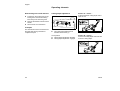
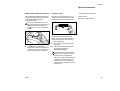
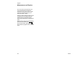
1
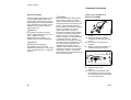
BA_U1_99_01.fm Seite 0 Freitag, 12. November 2004 10:10 10
STIH)
STIHL FW 20
Gebrauchsanleitung
Kasutusjuhend
Eksploatavimo
instrukcija
Èíñòðóêöèÿ çà óïîòðåáà
Navodilih za uporabo
Instruction Manual
Notice d’emploi
Instrucciones de servicio
Naputak za korišcenje
Skötselanvisning
Käyttöohje
Istruzioni d’uso
Betjeningsvejledning
Bruksanvisning
Návod k použití
Használati utasítás
Instruções de serviço
Návod na obsluhu
Handleiding
Èíñòðóêöèÿ ïî ýêñïëóàòàöèè
Lietoðanas instrukcija
²íñòðóêö³ÿ ç åêñïëóàòàö³¿
ïäçãßåò ÷ñÞóçò
Instrukcja u¿ytkowania
BA_SE_174_002_01_02.fm
English
Contents
Guide to Using this Manual
Guide to Using this Manual .............. 9
Safety Precautions ......................... 10
Assembling the unit ........................ 12
Operating elements ........................ 14
Special accessories ........................ 15
Maintenance and Repairs ............... 16
Pictograms
All the pictograms attached to the
machine are shown and explained in
this manual.
The operating and handling instructions
are supported by illustrations.
Symbols in text
© ANDREAS STIHL AG & Co. KG, 2004
0458 379 9921 A. M2,5. L4. T. Printed in Germany
Printed on chlorine-free paper.
Printing inks contain vegetable oils; paper can be recycled.
The individual steps or procedures
described in the manual may be marked
in different ways:
:
A bullet marks a step or procedure
without direct reference to an
illustration.
A description of a step or procedure that
refers directly to an illustration may
contain item numbers that appear in the
illustration.
Example:
Loosen the screw (1)
Lever (2) ...
STIHl
FW 20
9
English
Safety Precautions
In addition to the operating instructions,
this manual may contain paragraphs
that require your special attention. Such
paragraphs are marked with the
symbols described below:
Warning where there is a risk of an
accident or personal injury or
serious damage to property.
Caution where there is a risk of
damaging the machine or its
individual components.
Note or hint which is not essential
for using the machine, but may
improve the operator’s understanding of the situation and result
in better use of the machine.
Note or hint on correct procedure in
order to avoid damage to the
environment.
Equipment and features
This instruction manual may refer to
several models with different
features. Components that are not
installed on all models and related
applications are marked with an
asterisk (*). Such components may
be available as special accessories
from your STIHL dealer.
Engineering improvements
STIHL’s philosophy is to continually
improve all of its products. As a result,
engineering changes and improvements
are made from time to time. If the
operating characteristics or the
appearance of your machine differ from
those described in this manual, please
contact your STIHL dealer for
assistance.
Therefore some changes, modifications
and improvements may not be covered
in this manual.
10
Special precautionsmust
be taken when working
with the combined cut-off
machine and cart.
It is important that you
read, fully understand and
observe the following
safety precautions and
warnings. Read the
owner's manuals and
safety instructions of your TS 700 cut-off
machine and cart periodically. Careless
or improper use of any power tool may
cause serious or fatal injury.
Do not lend or rent your cut-off machine
and cart without the Owner's Manual. Be
sure that anyone using your cut-off
machine and cart understands the
information contained in these manuals.
Have your STIHL dealer show you how
to operate your cut-off machine with
cart. Observe all applicable local safety
regulations, standards and ordinances.
FW 20
English
! Warning !
Minors should never be allowed to use a
cut-off machine and cart. Bystanders,
especially children, and animals should
not be allowed in the area where a cutoff machine is in use. Never let the cutoff machine run unattended.
The cart
For parts of the cart, illustrations and
definitions of the parts see "Parts and
control".
!Warning !
Never modify a cut-off machine or cart in
any way. Only attachments supplied by
STIHL or expressly approved by STIHL
for use with the specific STIHL cut-off
machine model and cart are authorized.
Although certain unauthorized
attachments are usable with a STIHL
powerhead and cart, their use may, in
fact, be extremely dangerous.
FW 20
Mounting the cut-off machine
!Warning !
To reduce the risk of injury from loss of
control and subsequent wheel shatter
the cart has been approved by STIHL
only for use with the STIHL TS 700 cutoff machine model. Other cut-off
machines must not be mounted on the
cart.
For assembly, follow the procedure
described at the appropriate sections of
your owner's manuals.
Before operation of your cut-off machine
and cart, be sure that the cart and cut-off
machine are in good working order.
Check correct functioning of the
operating elements (e.g. throttle control,
cutting depth adjustment and follow the
appropriate chapters in the Owner's
Manuals).
Fueling
The cart must be parked so that it cannot
tip over or roll away when refueling the
cut-off machine mounted on the cart.
!Warning !
Gasoline is an extremely flammable fuel.
If spilled or ignited by a spark or other
ignition source, it can cause fire and
serious burn injury or property damage.
Use extreme caution when handling
gasoline or fuel mix. Do not smoke or
bring any fire or flame near the fuel. For
fueling instructions see chapter "Fuel" of
the owner's manual of your cut-off
machine.
11
English
Assembling the unit
During work
Sweep debris from the path of the wheel
as debris may cause flexing of the
abrasive wheel. This could result in high
frictional forces and thus greatly reduce
the engine power available for the actual
cutting work. Always use the cart to cut
in a straight line.
!Warning !
If the cart is pushed over objects, the
abrasive wheel may become wedged in
the cut and shatter! Always clear a path
for the cart and never work on uneven
surfaces.
!Warning !
To reduce the risk of injury from a cart
and cut-off machine tipping over and
subsequently causing wheel damage do
not work on uneven surfaces.
12
!Warning !
Use of this product can generate dust,
mists and fumes containing chemicals
known to cause serious or fatal injury or
illness. Control dust, mists and fumes at
the source where possible. A water
attachment kit is available for your cart
and cut-off machine and should be used
for dust suppression when wet cutting is
feasible. When the inhalation of dust,
mists and fumes cannot be eliminated,
the operator and any bystanders should
always wear a respirator approved by
NIOSH / MSHA for the material being
cut. See also the safety precautions on
dust, mists and fumes in the Owner's
Manual of the cut-off machine.
Move cart into working position
:
Turn star handle (1) anticlockwise
and move guide tube (2) to working
position A.
:
Tighten star handle down in
clockwise direction.
:
Steady the guide tube.
:
Move the lever (3) for cutting depth
adjustment to position A –
the cutting depth adjustment is
released.
For information on transporting,
maintenance, repair and storage of your
cut- off machine, see specific sections of
your cut-off machine manual.
FW 20
English
Mount the cut-off machine
:
Press the guide tube down in the
direction of the arrow until the
wheel (4) hovers above the ground
with the swivel arm.
:
Hold the cart in this position.
:
Move the lever (3) for cutting depth
adjustment to position B –
the cutting depth adjustment is
engaged.
:
Relieve the guide tube – the wheel
of the swivel arm rests on the
ground.
FW 20
:
Position the cut-off machine so that
the pins (5) protrude into the holes
in the support (6).
:
Turn the locking lever (11) over the
hand guard and engage it.
:
The locking pawl (12) advances and
holds the handle in position.
Mounting the throttle control
:
The handle (7) must rest in the
bracket (8) and the handle (9)
presses down into the holder (10).
:
Push the throttle control (13)
sideways onto the handle (9) and
engage it.
13
English
Operating elements
Dismounting the cut-off machine
:
Press down the locking pawl on the
locking lever and turn the locking
lever away from the hand guard.
:
Remove the throttle control from the
handle.
:
Dismount the cut-off machine.
Cutting depth adjustment
Position A – release –
to set the required cutting depth and to
enter the cut.
Transport
The star handle can be unscrewed and
the guide tube swung forwards for
compact transport.
:
The cutting depth adjustment is
actuated via the lever (1).
Lever position
A Cutting depth adjustment released
B Cutting depth adjustment engaged
14
Position B – engage –
to fix the set cutting depth and work with
a uniform cutting depth.
FW 20
English
Special accessories
Release with combination wrench
Throttle control
Cutting direction indicator set
If the cutting depth adjustment cannot be
released via the lever on the guide tube,
it can still be released with the
combination wrench.
To start the cut-off machine, refer to
"Starting / stopping the engine" in the
user manual for the cut-off machine.
Water tank set
Pressurized water tank set
The combination wrench can only
be used to release the cutting depth
adjustment when the engine is
switched off – do not touch the hot
muffler!
The throttle is not actuated via the
handle on the cut-off machine, but via
the throttle control on the guide tube.
:
:
To release the cutting depth
adjustment, insert the combination
wrench (2) in the hole (3) and press
down in the direction of the arrow.
:
For this purpose:
Press down and hold the locking
button (1).
Pull the throttle control (2) until it
contacts the guide tube –
full throttle position
The speed of the cut-off machine
depends on the distance between
throttle control and guide tube.
When the throttle control is released
completely (no-load setting), the
locking button must be pressed
again before the throttle control can
be actuated.
FW 20
15
English
Maintenance and Repairs
The user of this unit should carry out
only the maintenance operations
described in this manual. Other repair
work may be performed only by an
authorized STIHL dealer.
Warranty claims following repairs can be
accepted only if the repair has been
performed by an authorized STIHL
dealer using original STIHL replacement
parts.
Original STlHL parts can be identified by
the STIHL part number, the STIHl
logo and the STlHL parts symbol (.
The symbol may appear alone on small
parts.
16
FW 20
español / EE.UU
Notas referentes a estas
instrucciones de servicio
Notas referentes a estas
instrucciones de servicio ................
Para su seguridad ..........................
Completar la máquina ....................
Elementos de mando .....................
Accesorios especiales ....................
Informaciones para la reparación ...
© ANDREAS STIHL AG & Co. KG, 2004
0458 379 9921 A. M2,5. L4. T. Printed in Germany
25
26
28
30
31
32
Símbolos gráficos
Todos los símbolos gráficos que se
pueden ver en el motoimplemento están
explicados en estas instrucciones de
servicio.
El manejo correcto está descrito y
explicado adicionalmente con
ilustraciones.
Marcación de los párrafos de
texto
Impreso en papel sin cloro.
Las tintas contienen aceites vegetales,el papel es reciclable.
BA_SE_174_002_03_02.fm
Contenido
Los pasos de manejo descritos pueden
tener distintas marcaciones:
:
Paso de manejo que no tiene
relación directa con la ilustración
Paso de manejo que tiene relación
directa con la ilustración situada por
encima o al margen del texto con
referencia a un número de posición.
Ejemplo:
Aflojar el
1 = tornillo
2 = Palanca ...
STIHl
FW 20
25
español / EE.UU
Para su seguridad
Estas instrucciones de servicio pueden
contener, además de la descripción del
manejo, párrafos de texto con un
significado adicional. Estos párrafos
están marcados con uno de los
símbolos descritos a continuación:
Advertencia de peligro de accidente
y de riesgo de lesiones para
personas y advertencia de graves
daños materiales.
Advertencia de daños o deterioros
del motoimplemento o de los
diferentes componentes.
Advertencia que no es realmente
necesaria para el manejo del
motoimplemento pero, sin
embargo, puede facilitar tanto la
comprensión del texto como la
utilización del motoimplemento.
Advertencia para evitar daños
ecológicos.
Volumen de suministro /
equipamiento
Estas instrucciones de servicio se
refieren a modelos que se entregan
en distintas versiones. Piezas que
no están montadas en todos los
modelos y las respectivas
aplicaciones resultantes están
marcadas con *. Las piezas no
contenidas en el volumen de
suministro y marcadas con * están
disponibles como accesorios
especiales en la tienda de su
distribuidor STIHL.
Perfeccionamiento técnico
STIHL trabaja constantemente en el
desarrollo de todos sus motoimplementos. Nos reservamos el
derecho de introducir modificaciones
referentes al diseño, la técnica y al
equipamiento.
Por esta razón no se puede hacer valer
ningún derecho en base de los datos y
las ilustraciones incluidos en estas
instrucciones de servicio.
Será necesario observar
medidas de seguridad
especiales al trabajar con
la combinación del tren de
guía / tronzadora.
Leer atentamente las
indicaciones de seguridad
siguientes y tenerlas en
cuenta. Leer de vez en
cuando las Instrucciones
de servicio y las
indicaciones referentes a la seguridad
de la TS 700 y del tren de guía. El uso
negligente o erróneo de una máquina a
motor puede originar lesiones graves o
mortales.
No prestar o alquilar la tronzadora y el
tren de guía jamás sin las Instrucciones
de servicio. Todo usuario de la
tronzadora y del tren de guía tiene que
observar las indicaciones que figuran en
las Instrucciones de servicio.
Hacer que el vendedor de productos
STIHL le muestre cómo manejar de
forma segura la tronzadora y el tren de
guía.
Observar las normas de seguridad
específicas del país, de p. ej., las
Asociaciones Profesionales del ramo,
organismos sociales y autoridades
competentes para asuntos de
prevención de accidentes en el trabajo.
26
FW 20
español / EE.UU
! Atención:
Los menores de edad no deberán
trabajar con la tronzadora y el tren de
guía. No permitir que se acerquen niños,
espectadores ni animales. No dejar
nunca la tronzadora en marcha sin
vigilarla.
Tren de guía
Para los componentes del tren de guía,
las ilustraciones y definiciones, véase el
catálogo “Componentes importantes”.
!Atención:
No modificar nunca la tronzadora ni el
tren de guía. Emplear únicamente
dispositivos de acople suministrados o
expresamente autorizados por STIHL
para acoplarlos a esta tronzadora y al
tren de guía. Aun cuando determinados
dispositivos de acople no autorizados se
puedan emplear con la unidad de motor
STIHL y el tren de guía, puede resultar
peligrosa su utilización.
FW 20
Montar la tronzadora
Repostar combustible
!Atención:
Para repostar combustible en la
tronzadora montada en el tren de guía,
éste deberá encontrarse asegurado
contra vuelcos y contra el deslizamiento.
Para el acople en el tren de guía, sólo se
autoriza la tronzadora STIHL TS 700. El
montaje de otras tronzadoras no se
admite – peligro de accidente por rotura
del disco en caso de perderse el control.
Al efectuar el ensamblaje, tener en
cuenta el correspondiente capítulo de
las Instrucciones de servicio.
Comprobar el tren de guía y la
tronzadora antes y después del acople
en cuanto a estado de funcionamiento
seguro. Para el funcionamiento de los
elementos de mando (p. ej., el
accionamiento del gas, la regulación de
la profundidad de corte) – tener en
cuenta el capítulo correspondiente de
las Instrucciones de servicio.
!Atención:
La gasolina es extremadamente fácil de
inflamar. En el caso de que se derrame
o de que se encienda por una chispa u
otra fuente de encendido, pueden
producirse incendios, quemaduras
graves o daños materiales. Poner
especial atención al manipular con
gasolina o mezcla de combustible.
Guardar distancia de fuego abierto. No
fumar. Los detalles sobre el repostaje se
encuentran en el correspondiente
capítulo de las Instrucciones de servicio
de la tronzadora.
27
español / EE.UU
Completar la máquina
Durante el trabajo
Quitar los objetos del recorrido a cortar
ya que pueden ladear el disco. Ello
podría originar altas fuerzas de fricción
disminuyendo por lo tanto la potencia de
motor disponible para efectuar el corte.
Emplear el tren de guía únicamente
para cortes rectos.
!Atención:
Si se empuja el tren de guía sobre
objetos, puede ladearse el disco en el
corte – ¡peligro de rotura!
Despejar el sector de trabajo – no
trabajar sobre una base desnivelada.
!Atención:
No trabajar sobre superficies
desniveladas con la tronzadora
montada en el tren de guía – éste puede
volcar y romperse el disco – ¡peligro de
lesiones!
!Atención:
El uso de la máquina puede producir
polvo, niebla y vapores, los cuales
pueden contener sustancias químicas
de las que se sabe que pueden provocar
lesiones o enfermedades serias. El
polvo, la niebla y los vapores se deben
evitar en lo posible en su lugar de
origen. Para el tren de guía y la
tronzadora se dispone de un empalme
de agua que se debería utilizar para
aglutinar el polvo, si resulta posible
cortar en mojado. Si no se puede evitar
la inhalación de polvos, nieblas y
vapores tóxicos, el operario y aquellos
que estén cerca de él deberían ponerse
un protector para la respiración de
NIOSH/MSHA apropiado para el
material a cortar. Tener en cuenta las
indicaciones referentes a la seguridad
sobre polvos, nieblas y vapores que
figuran también en las Instrucciones de
servicio de la tronzadora.
Poner el tren de guía en la
posición de trabajo
Girar el
1 = asidero de estrella en sentido
contrario al de las agujas del reloj y
poner el
2 = tubo de guía en la posición de
trabajo A
:
Apretar el asidero de estrella en el
sentido de las agujas del reloj
:
Sujetar el tubo de guía
Poner la
3 = palanca para la regulación de la
profundidad de corte en la posición
A – la regulación de la profundidad
de corte se desenclava
28
FW 20
español / EE.UU
Montar la tronzadora
:
Oprimir el tubo de guía hacia abajo,
en el sentido de la flecha, hasta que
la
4 = rueda del brazo oscilante esté
suspendida sobre el suelo
:
Sujetar el tren de guía en esta
posición
Poner la
3 = palanca para la regulación de la
profundidad de corte en la posición
B – la regulación de la profundidad
de corte se enclava
:
Aplicar la tronzadora, de manera
que los
5= pernos penetren en los taladros del
6= apoyo
Girar la
11= palanca de enclavamiento sobre el
protector salvamanos y encastrarla
El
12= trinquete de bloqueo sale y la
empuñadura queda fijada
Montaje del acelerador
El
7= asidero tubular debe descansar en
el
8= estribo de retención y poner la
9= empuñadura en el
10= soporte oprimiéndola hacia abajo
Insertar el
13= acelerador desde el lado en la
9= empuñadura y encastrarlo
Descargar el tubo de guía – la rueda
del brazo oscilante se apoya sobre
el suelo
FW 20
29
español / EE.UU
Elementos de mando
Desmontar la tronzadora
:
Introducir el trinquete de bloqueo en
la palanca de enclavamiento
oprimiéndolo y apartar dicha
palanca del protector salvamanos
girándola
:
Quitar el acelerador de la
empuñadura
:
Quitar la tronzadora
Regulación de la profundidad de
corte
Posición A – desenclavar –
Para ajustar la profundidad de corte
deseada y para penetrar en el corte
Transporte
Para ahorrar espacio en el transporte,
se puede aflojar el asidero de estrella y
plegar el tren de guía hacia delante.
La regulación de la profundidad de
corte se acciona con la
1 = palanca
Posiciones de la palanca
A Regulación de la profundidad de
corte, desenclavada
B Regulación de la profundidad de
corte, enclavada
30
Posición B – enclavar –
para fijar la profundidad de corte
ajustada y para trabajar con una
profundidad de corte homogénea
FW 20
español / EE.UU
Accesorios especiales
Desenclavamiento con la llave
universal
Si no resulta posible efectuar el
desenclavamiento mediante la palanca
en el tubo de guía, se puede
desenclavar la regulación de la
profundidad de corte con la llave
universal.
Accionamiento del gas
Juego indicador del sentido de corte
Para arrancar la tronzadora, véase
“Arrancar/parar el motor” en las
Instrucciones de servicio de la
tronzadora.
Juego depósito de agua
Juego depósito de agua a presión
El desenclavamiento con la llave
universal sólo se deberá efectuar
estando desconectado el motor –
no tocar el silenciador caliente
El accionamiento del gas no se efectúa
por medio de la empuñadura de la
tronzadora, sino con el acelerador del
tubo de guía.
Para ello, oprimir el
1 = botón de bloqueo y mantenerlo
Para el desenclavamiento, insertar
la
2 = llave universal en el
3 = taladro y oprimirla hacia abajo en el
sentido de la flecha
Tirar del
2 = acelerador hasta que tope en el
tubo de guía – posición de pleno
gas
El número de revoluciones de la
tronzadora está en función de la
distancia del acelerador respecto al
tubo de guía.
Si se suelta por completo el
acelerador (posición de ralentí),
habrá que oprimir el botón de
bloqueo para volver a dar gas.
FW 20
31
español / EE.UU
Informaciones para la
reparación
El usuario del motoimplemento debe
efectuar únicamente aquellos trabajos
de mantenimiento y de cuidado que se
hayan descrito en estas instrucciones
de servicio. Reparaciones más amplias
deberán ser efectuadas únicamente por
los talleres autorizados STIHL.
El derecho de garantía después de una
reparación prevalece únicamente si los
trabajos fueron realizados por un taller
autorizado STIHL utilizando piezas de
repuesto originales de STIHL.
Las piezas originales de repuesto STIHL
se reconocen por el N.° de Referencia
STIHL, por el logotipo STIHl y a
veces por el símbolo para piezas de
repuesto STIHL (. En piezas
pequeñas, este símbolo también puede
ir solo, sin logotipo.
32
FW 20
BA_U2_99_01.fm Seite 1 Donnerstag, 11. November 2004 7:48 07
D Gebrauchsanleitung
1-8
H Használati utasítás
89 - 96
G Instruction Manual
9 - 16
P Instruções de serviço
97 - 104
F Notice d’emploi
17 - 24
s Návod na obsluhu
105 - 112
E Instrucciones de
servicio
25 - 32
n Handleiding
113 - 120
h Naputak za korišcenje
33 - 40
R Èíñòðóêöèÿ ïî
ýêñïëóàòàöèè
121 - 128
S Skötselanvisning
41 - 48
L Lietoðanas instrukcija
129 - 136
f Käyttöohje
49 - 56
u ²íñòðóêö³ÿ ç åêñïëóàòàö³¿
137 - 144
I Istruzioni d’uso
57 - 64
g ïäçãßåò ÷ñÞóçò
145 - 152
d Betjeningsvejledning
65 - 72
J
N Bruksanvisning
73 - 80
p Instrukcja u¿ytkowania
161 - 168
c Návod k použití
81 - 88
e Kasutusjuhend
169 - 176
153 - 160
l Eksploatavimo
instrukcija
177 - 184
B Èíñòðóêöèÿ çà óïîòðåáà
185 - 192
y Navodilih za uporabo
193 - 200
BA_U4_99_01.fm Seite 1 Donnerstag, 11. November 2004 7:46 07
0458 379 9921 A
INT 1