1
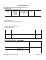
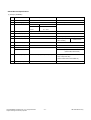
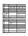
Internal Use Only
North/Latin America
Europe/Africa
Asia/Oceania
http://aic.lgservice.com
http://eic.lgservice.com
http://biz.lgservice.com
PLASMA TV
MANUAL DE SERVICIO
CHASIS : PP81D
MODELO : 32PC5RA
32PC5RA-MF
ATENCIÓN
Antes de dar servicio al chasis, lea las PRECAUCIONES DE SEGURIDAD
en este manual.
CONTENIDO
CONTENIDO ............................................................................................................................ 2
PRECAUCIONES DE SEGURIDAD .........................................................................................3
ESPECIFICACIONES ................................................................................................................4
INSTRUCCIONES DE AJUSTE ...............................................................................................7
GUÍA PARA SOLUCIONES DE PROBLEMAS.......................................................................16
DIAGRAMA EN BLOQUE ......................................................................................................23
VISTA EN DESPIECE .............................................................................................................25
DIAGRAMA ESQUEMÁTICO......................................................................................................
TABLERO DE CIRCUITO IMPRESO ..........................................................................................
Copyright©2008 LG Electronics. Inc. All right reserved.
Only for training and service purposes
-2-
LGE Internal Use Only
PRECAUCIONES DE SEGURIDAD
ADVERTENCIA: Antes de dar servicio a este chasis, lea "PRECAUCIONES RESPECTO A RADIACION POR RAYOS X",
"INSTRUCCIONES DE SEGURIDAD" y "AVISO SOBRE SEGURIDAD DE PRODUCTOS"
INSTRUCCIONES DE SEGURIDAD
1. Cuando el receptor está en operación, se producen voltajes
potencialmente tan altos como 25,000-29,000 voltios. Operar
el receptor fuera de su gabinete o con la tapa trasera
removida puede causar peligro de choque eléctrico.
(1) Nadie debe intentar dar servicio si no está debidamente
familiarizado con las precauciones que son necesarias
cuando se trabaja con un equipo de alto voltaje.
(2) Siempre descargue el ánodo del tubo de la imagen a tierra
para evitar el riesgo de choque eléctrico antes de remover
la tapa del ánodo.
(3) Descargue completamente el alto potencial del tubo de
imagen antes de manipularlo. El tubo de la imagen es de
alto vacío y, si se rompe, los fragmentos de vidrio salen
despedidos violentamente.
2. Si se quemara algún fusible de este receptor de televisión,
reemplácelo con otro especificado en la lista de partes.
3. Cuando reemplace tableros o plaquetas de circuitos,
cuidadosamente enrolle sus alambres alrededor de las
terminales antes de soldar.
4. Cuando reemplace un resistencia de vataje (resistor de
película de óxido metálico) en el Tablero o Plaqueta de
circuitos, mantenga la resistencia a un mínimo de 10mm de
distancia.
5. Mantenga los alambres lejos de componentes de alto voltaje
o de alta temperatura.
6. Este receptor de televisión debe conectarse a una fuente de
100 a 240 V AC.
7. Antes de devolver este aparato al cliente, haga una
verificación de fuga de corriente sobre las partes metálicas
del gabinete expuestas, tales como antenas, terminales,
cabezas de tornillos, tapas de metal, palancas de control etc.,
para estar seguro de que el equipo funciona sin peligro de
choque eléctrico. Enchufe el cordón directamente al
tomacorriente de la línea de AC 100-240V.
No utilice una línea aislada de transformador durante esta
verificación. Use un voltímetro de 1000 Ohmios por voltio
de sensibilidad o más, en la forma que se describe a
continuación.
Cuando la unidad está ya conectada a la AC, pulse el
conmutador primero poniéndolo en "ON" (encendiendo) y
luego en "OFF" (apagando), mida desde un punto de tierra
conocido, tal como una (cañería de metal, una manija
metálica, una tubería etc.) a todas las partes metálicas
expuestas del receptor de televisión (antenas, manijas de
metal, gabinetes de metal, cubiertas de metal, palancas de
control etc.,) especialmente cualquiera de las partes
metálicas expuestas que puedan ofrecer un camino hacia el
chasis. Ninguna medición de corriente eléctrica debe exceder
de 0.5 miliamperios. Repita la prueba cambiando la posición
del enchufe en el tomacorriente. Cualquier medición que no
esté dentro de los límites especificados aquí representan un
riesgo potencial de choque eléctrico que debe ser eliminado
antes de devolver el equipo al cliente.
La lectura no
debe
(READING
SHOULD
exceder
0.5mA
NO T BEde ABO
VE
0.5mA)
LEAKAGE
Probador
CURRENT
de fuga de
corriente
TESTER
Aparato
DEVICE
bajo
UNDER
TEST
examen
+Pruebe
todas
TEST
ALL
MET AL
lasEXPOSED
superficies
SURFA CES
metálicas
2-WIRE CORD
Tambien pruebe cón
ALSO
TEST WITH
los enchufes
al reves
PLUG REVERSED
(utilizando
(USING
AC adaptador
ADAPTER
en caso
PLUG
AS necesario)
REQUIRED)
Tierra
EAR
TH
suelo
GROUND
AVISO SOBRE SEGURIDAD DE PRODUCTOS
Muchas de las partes, electricas y mecánicas en este chasis tienen caracteristicas relacionadas con la seguridad. Estas
caracteristicas frecuentemente pasan desapercibidas en las inspecciones visuales y la proteccion que proporcionan contra la
RADIACION DE RAYOS-X no siempre necesariamente se obtiene al mismo grado cuando se reemplazan piezas o componentes
diseñados para voltajes o vatajes mayores, etc. Las piezas que tienen estas caracteristicas de seguridad se identifican por la
marca
impresa sobre el diagrama esquematico. Antes de reemplazar alguno de esos componente, lea cuidadosamente la
lista de este manual. El uso de partes de reemplazo que no tengan las mismas caracteristicas de seguridad, como se especifica
en la lista de partes, puede crear Radiacion de Rayos-X.
Copyright©2008 LG Electronics. Inc. All right reserved.
Only for training and service purposes
-3-
LGE Internal Use Only
ESPECIFICACIONES
NOTE : Specifications and others are subject to change without notice for improvement.
V
Application Range
This spec sheet is applied to PDP TV used PP81D Chassis.
V
Chassis
Model Name
Market
Brand
PP81D
32PC5RA-TD
NON EU
LG
32PC5RA-MF
Central and South America
32PC53-ZB
EU
32PC54-ZD
EU
Remark
Specification
Each part is tested as below without special appointment.
1) Temperature : 25±5°C (77±9°F), CST : 40±5
2) Relative Humidity: 65±10%
3) Power Voltage: Standard Input voltage (100-240V~, 50/60Hz)
* Standard Voltage of each product is marked by models.
4) Specification and performance of each parts are followed each drawing and specification by part number in accordance with SBOM.
5) The receiver must be operated for about 20 minutes prior to the adjustment.
V
Test Method
1) Performance : LGE TV test method followed.
2) Demanded other specification
Safety : CE, IEC specification
EMC : CE, IEC
Model
Market
32PC53-ZB
EU
Appliance
Remark
Safety : IEC/EN60065
32PC54-ZD
32PC5RA-TD
NON -EU
32PC5RA-MF
Central and South
EMI
: EN55013
EMS
: EN55020
TEST
Safety : IEC/EN60065
EMI
TEST
: CISPR13
America
V
Module General Specification(32” WVGA PDP Module)
No
Item
Specification
1
Display Screen Device
32 inch 16:9 Color Plasma Display Module
2
Aspect Ratio
16:9
3
PDP Module
PDP32F#####,
Remark
PDP
Glass Filter
RGB Closed(Well) Type
4
Operating Environment
1) Temp. : 0 ~ 60 deg
LGE SPEC.
2) Humidity : 20 ~ 80 %
5
Storage Environment
3) Temp. : -20 ~ 60 deg
4) Humidity : 10 ~ 90 %
6
Input Voltage
AC 100-240V~, 50/60Hz
Copyright©2008 LG Electronics. Inc. All right reserved.
Only for training and service purposes
-4-
Maker: Sanken
LGE Internal Use Only
V
Model General Specification
(1) EU Spec.(ZA/ZB/ZD)
No
Item
Specification
1
Market
EU
2
Broadcasting system
PAL BG/I/DK, SECAM
3
Available Channel
BAND
Remark
SECAM-L spec out
PAL
VHF/UHF
C1 ~ C69
CATV
S1 ~ S47
4
Receiving system
Upper Heterodyne
5
SCART Input(2EA)
PAL
Full Scart 1EA, Harf 1EA
6
Video Input (1EA)
PAL
Side AV(Except 32PC models)
7
S-Video Input (1EA)
PAL
Side AV(Except
S-Video Priority
32PC models)
8
Component Input (1EA)
Y/Cb/Cr, Y/Pb/Pr
9
RGB Input(1EA)
RGB-PC
10
HDMI
1EA
HDMI-DTV
Input
2EA
REAR HDMI(Only 42/50PG100R-ZA)
REAR HDMI(Only 42/50PG200R-ZA
(32PC53-ZB, 32PC54-ZD)
11
Audio Input (5EA)
PC Audio, AV(3EA), Component(1EA)
L/R Input(PC 1EA, SCART 2EA, SIDE AV
1EA, Component 1EA)
(32PC models dosen’t have SIDE AV)
12
USB Input(1EA)
Divx, MP3, JPEG
Copyright©2008 LG Electronics. Inc. All right reserved.
Only for training and service purposes
SIDE USB: only for 42/50PG600R-ZA
-5-
LGE Internal Use Only
(2) NON-EU Spec.(TA/TD)
No
Item
Specification
1
Market
NON EU/CHINA
2
Broadcasting system
PAL/SECAM/BG/I/DK, NTSC-M
3
Available Channel
BAND
Remark
PAL
NTSC
VHF/UHF
E2 ~ C69
2 ~ 78
CATV
S21 ~ S47
1 ~ 71
China(DK)
Australia(BG)
VHF/UHF
C1 ~ C62
C1 ~ C75
CATV
S1 ~ S41
S2 ~ S44
4
Receiving system
Upper Heterodyne
5
Video Input(2EA)
PAL, SECAM, NTSC
Rear 1EA, Side 1EA(Except 32PC5RA)
6
AV Output (1EA)
PAL, SECAM, NTSC
Rear 1EA
7
S-Video Input (1EA)
PAL, SECAM, NTSC
Side(Except 32PC5RA)
8
Component Input (2EA)
Y/Cb/Cr, Y/Pb/Pr
9
RGB Input(1EA)
RGB-PC, S/W Upgrade
10
HDMI
2EA
HDMI-DTV, Only PCM MODE
Input
3EA
S-video Priority
REAR HDMI(2)
SIDE HDMI(1), REAR HDMI(2) : Only for
42/50PG60UR-TA, 50/60PG70FR-TB,
50PG30FR-TB
11
Audio Input (5EA)
PC Audio, Component(2EA), AV(2EA),
L/R Input(PC 1EA, Component 2EA, Rear
1EA, Side 1EA(Except 32PC5RA))
12
RS-232C(1EA)
Remote Control
13
USB Input(1EA)
Divx, MP3, JPEG
SIDE USB: only for 42/50PG60UR-TA
(3) Central and South America Spec.(MA/MB/MF)
No
Item
Specification
1
Market
Central and South America
2
Broadcasting system
NTSC, PAL-M, PAL-N
3
Available Channel
BAND
NTSC
VHF
2 ~ 13
UHF
14 ~ 69
CATV
1 ~ 125
Remark
4
Receiving system
Upper Heterodyne
5
Video Input(2EA)
NTSC, PAL-M/N
Rear 1EA, Side 1EA(Except 32PC5RA)
6
AV Output (1EA)
NTSC, PAL-M/N
Rear 1EA
7
S-Video Input (1EA)
NTSC, PAL-M/N
Side(Except 32PC5RA)
8
Component Input (2EA)
Y/Cb/Cr, Y/Pb/Pr
9
RGB Input(1EA)
RGB-PC, S/W Upgrade
10
HDMI
2EA
HDMI-DTV, Only PCM MODE
Input
3EA
S-video Priority
REAR HDMI(2)
SIDE HDMI(1), REAR HDMI(2) : Only for
42/50PG60UR-MA, 50/60PG70FR-MB
11
Audio Input (5EA)
PC Audio, Component(2EA), AV(2EA),
L/R Input(PC 1EA, Component 2EA, Rear
1EA, Side 1EA(Except 32PC5RA))
12
RS-232C(1EA)
Remote Control
Copyright©2008 LG Electronics. Inc. All right reserved.
Only for training and service purposes
-6-
LGE Internal Use Only
INSTRUCCIONES DE AJUSTE
(2) Confirmation
1. Application Range
1) We confirm whether “0xF1(offset), 0xF2(gain)” address of
EEPROM “0xBC” is “0xAA” or not.
2) If “0xF1”, “0xF2” address of EEPROM “0xBC” isn’t “0xAA”,
we adjust once more
3) We can confirm the ADC values from “0x00~0x05”
addresses in a page “0xBC”
This spec. sheet is applied to all of the PP81D Chassis.
2. Specification
(1) Because this is not a hot chassis, it is not necessary to use
an isolation transformer. However, the use of isolation
transformer will help protect test instrument.
(2) Adjustment must be done in the correct order.
(3) The adjustment must be performed in the circumstance of
25±5cC of temperature and 65±10% of relative humidity if
there is no specific designation.
(4) The input voltage of the receiver must keep 100~240V,
50/60Hz.
(5) Before adjustment, execute Heat-Run for 30 minutes at RF
no signal.
[ Manual ADC process using Service Remocon. After enter
Service Mode by pushing “ADJ” key, execute “Auto-RGB” by
pushing “G” key at “Auto-RGB”.
3-2. COMPONENT input ADC
(1) Component Gain/Offset Adjustment
1) Convert to Component in Input-source
2) Signal equipment displays
Impress Resolution 720P
MODEL : 217 in Pattern Generator(720P/60Hz 100%
Color Bar Mode)
PATTERN : 65 in Pattern Generator( MSPG-925 SERISE)
3. ADC calibration
3-1. PC input ADC
(1) Auto RGB Gain/Offset Adjustment
1) Convert to PC in Input-source
2) Signal equipment displays
Output Voltage : 700 mVp-p
Impress Resolution XGA (1024 x 768 @ 60Hz)
Model : 60 in Pattern Generator
(1024 x 768 @ 60Hz Black and White Pattern)
Pattern : 54 in Pattern Generator (MSPG-925 SERISE)
[1/2 Black & White Pattern (Refer below picture)].
<Fig. 1> Adjustment pattern(RGB PC)
Adjustment pattern (COMPONENT)
3) Adjust by commanding AUTO_COLOR_ADJUST(0xF1)
0x00 0x02 instruction
(2) Confirmation
1) We confirm whether “0xF3(offset), 0xF4(gain)” address of
EEPROM “0xBC” is “0xAA” or not.
2) If “0xF3”, “0xF4” address of EEPROM “0xBC” isn’t “0xAA”,
we adjust once more
3) We can confirm the ADC values from “0x06~0x0B”
addresses in a page “0xBC”
[ Manual ADC process using Service Remocon. After enter
Service Mode by pushing “ADJ” key, execute “Auto-RGB” by
pushing “G” key at “Auto-RGB”.
3) Adjust by commanding AUTO_COLOR_ADJUST(0xF1)
0x00 0x02 instruction.
Copyright©2008 LG Electronics. Inc. All right reserved.
Only for training and service purposes
-7-
LGE Internal Use Only
4. PCB Assembly Adjustment Items
5. S/W Program Download
4-1. Option Adjustment Following BOM
5-1. Profile
Tool Option1
Tool Option2
Area Option
This is for downloading the s/w to the flash memory of the
IC803
5-2. Equipment
(1) PC
(2) ISP_tool program
(3) Download jig
5-3. Connection Structure
<Fig. 2>
* Profile: Must be changed the option value because being
different with some setting value depend on module, inch
and market
* Equipment : Adjustment Remote Controller
5-4. Connection Condition
(1) Push the IN-START key in the Adjust R/C.
(2) Input the Option Number that was specified in the BOM,
into the Shipping area.
(3) Select “Tool Option1/ Tool Option2/ Area Option” by using
D / E (CH+/-) key, and press the number key(0~9)
consecutively
ex) If the value of Tool Option1 is 7, input the data using
number key “7” (Fig. 2)
Caution: Don’t Push “IN-STOP” key after PCB assembly
adjustment.
(1) IC name and circuit number : Flash Memory and IC803
(2) Use voltage : 3.3V (5 pin)
(3) SCL : 15 pin
(4) SDA : 12 pin
(5) Tact time : about 2min and 30seconds
6. Download Method (PCB Ass’y)
6-1. Preliminary Steps
- HD
(4) Adjustment method
Before PCBA check, have to change the Tool option and
Area option
[ About PDP
After done all adjustments, Press IN-START button and
compare Tool option and Area option value with its BOM, if it
is correctly same then Change “RF mode” and then unplug
the AC cable.
If it is not same, then correct it same with BOM and unplug AC
cable.
For correct it to the model°Øs module from factory JIG model.
[ Don’t push The IN-STOP KEY after completing the function
inspection.
Copyright©2008 LG Electronics. Inc. All right reserved.
Only for training and service purposes
- FHD
-8-
LGE Internal Use Only
(4) Read and write bin file
Click “(1)Read” tab, and then load download file(XXXX.bin)
by clicking “Read”.
(1) Connect the download jig to D-sub jack
(2) Connect the PC to USB jack
(5) Click “Auto(2)” tab and set as below
(6) Click “Run(3)”.
(7) After downloading, check “OK(4)” message.
6-2. Download Steps
(1) Execute ‘ISP Tool’ program in PC, then a main window will
be opened
(2) Click the connect button and confirm “Dialog Box”.
[ Notice : From this sentence, All working is mass production.
(3) Click the config button and change speed
E2PROM Device setting: over the 350Khz
Copyright©2008 LG Electronics. Inc. All right reserved.
Only for training and service purposes
-9-
LGE Internal Use Only
<HDMI 1 : 256bytes>
7. EDID(The Extended Display
Identification Data) / DDC
(Display Data Channel) Download
[ Caution
- Use the proper signal cable for EDID Download
- Never connect HDMI & D-SUB Cable at the same time.
- Use the proper cables below for EDID Writing
7-1. Profile: To be possible for plug and play
7-2. Equipment
(1) Adjusting PC with S/W for writing EDID Data.(S/W: EDID
TESTER Ver.2.5)
(2) A Jig for EDID Download
(3) Cable : Serial(9Pin or USB) to D-sub 15Pin cable, D-sub
15Pin cable, DVI to HDMI cable.
<HDMI 2 : 256bytes>
7-3. Connection Structure
<Fig. 3> Connection Diagram of DDC Download
Caution: Never connect HDMI & D-SUB Cable at the same time.
<HDMI 3 : 256bytes>
7-4. EDID Data
O
XGA/WXGA/Full HD EDID DATA
<Analog : 128bytes>
Copyright©2008 LG Electronics. Inc. All right reserved.
Only for training and service purposes
- 10 -
LGE Internal Use Only
O
Detail EDID Options are below (ⓐ, ⓑ, ⓒ, ⓓ, ⓔ)
7-5. Preparation for Adjustment
(1) As above Fig. 3, Connect the Set, EDID Download Jig,,
PC & Cable
(2) Turn on the PC & EDID Download Jig. And Execute the
S/W : EDID TESTER Ver.2.5
(3) Set up the S/W option
Repeat Number : 5
Device Address : A0
PageByte : 8
ⓐ Product ID
(4) Power on the Set
ⓑ Serial No
=> Controlled on production line
1) Sequence of Adjustment
ⓒ Month, Year
=> Controlled on production line:
ex) Monthly: ‘11’ -> ‘0B’
Year: ‘2007’ -> ‘11’
1. DDC data of Analog-RGB
(1) Init the data
ⓓ Model Name(Hex)
ⓔ Checksum
=> Changeable by total EDID data
(2) Load the EDID data.(Open File).
1) Analog(128Byte)
2) HDMI 1/2/3(256Byte)
(3) Set the S/W as below.
Copyright©2008 LG Electronics. Inc. All right reserved.
Only for training and service purposes
- 11 -
LGE Internal Use Only
(4) Push the “Write Data & Verify” button. And confirm “Yes”.
8. HDCP(High-Bandwidth Digital Contents Protection)
[ Confirmation
Before HDCP Download, you have to Set the Configuration
that CMD delay.
-> Configuration -> Option-> I2C delay(Write Byte : 0.5 ms,
Read Byte : 0.5ms, Read CMD Byte : 0.5ms)
(1) Connect D-sub Signal Cable to D-Sub Jack
(2) Input HDCP key with HDCP-key- in-program
(3) HDCP Key value is stored on Main M-STAR
IC(LGE6891DD) which is 0x80~0x90 addresses of
0x00~0x01 page(EEPROM MAP PAGE0~PAGE1 / START
:A080)
(4) AC off/on and on HDCP button of MSPG925 and confirm
whether picture is displayed or not of using MSPG925
(5) HDCP Key value is different among the sets
(5) If the writing is finished, you will see the “OK” message.
Copyright©2008 LG Electronics. Inc. All right reserved.
Only for training and service purposes
- 12 -
LGE Internal Use Only
9. Adjustment of White Balance
9-1. Purpose and Principle for Adjustment
of the Color Temperature
(1) Purpose: Adjust the color temperature to reduce the
deviation of the module color temperature.
(2) Principle : To adjust the white balance without the
saturation, Fix the one of R/G/B gain to C0 and decrease
the others.
(3) Adjustment mode: Two modes of Cool and Warm
(Cool data is automatically calibrated by the Medium data)
9-2. Required Equipment
(1) Remote controller for adjustment
(2) Color Analyzer : CA-100+ or CA-210 or same product
- PLASMA TV(ch : 10)
(3) Auto W/B adjustment instrument(only for Auto adjustment)
- Do the white balance adjustment under the 10LUX
(1) Enter the adjustment mode of the white balance
- Enter the white balance adjustment mode at the same time
heat-run mode when pushing the power on by power only
key
- Maintain the white balance adjustment mode with same
condition of Heat-run
- Maintain after AC off/on in status of Heat-run pattern display
(2) Release the white balance adjustment mode
- Release the adjust mode after AC off/on or std-by off/on in
status of finishing the Hear-run mode
- push the “power on” key(IIC Mode) on Adjust remotecontroller.
- Release the Adjust mode when receiving the aging off
command(F3 00 00) from adjustment equipment)
(3) Enter the adjust mode of white balance
- Enter the white balance adjustment mode with aging
command(F3, 00, FF)
O
Color Temperature & Color Coordinates Setting
- When adjusting the Color Temperature, Color Analyzer CA210(Matrix should be corrected through CH10 of CS-1000)
should be used. When CA-210 have used, it don’t need to fit
the CH10.
- Adjust the Color Temperature based below adjustment color
coordinates.
O
Target Value CA-210(LCD : CH 9, PDP : CH10), CA-100(PDP)
(Standard color coordinate and temperature when using the
CA-100+ or CA210 equipment)
[ Notice: When using the Color Analyzer with PDP,
recommend the CA-100 more than CA-210.
If CA-100 can not available, it is also good to use the CA-210.
(4) PC (for communication through RGB)
(5) Pattern Generator (MSPG-925FA etc.)
-Before white balance, press the ADJ key 2times and do
the reset like Fig. 4
-To enter White-balance mode, press the ADJ key 2times.
[ Caution: System control Host should be “DDC” for adjustment.
O
<Fig. 4>
Synchronization relation between PSM and CSM
PSM
CSM
Vivid
Cool
Mild
Warm
9-3. Connecting Diagram of Equipment for
Measuring (For Automatic Adjustment)
(method 1, using IIC, You connect RGB Cable)
Copyright©2008 LG Electronics. Inc. All right reserved.
Only for training and service purposes
- 13 -
LGE Internal Use Only
O
DDC Adjustment Command Set
Adjustment
Adjustment
Adjustment
[ R/G/B GAIN max value : C0
9-4. Connecting Diagram of Equipment for
Measuring (For Automatic Adjustment)
(method2, using RS-232C, You connect RS-232C Cable)
- Maintain the white balance adjustment mode with same
condition of Heat-run
- Maintain after AC off/on in status of Heat-run pattern display
(2) Release the white balance adjustment mode
- Release the adjust mode after AC off/on or std-by off/on in
status of finishing the Hear-run mode
- push the “Tilt” key (RS-232C Mode) on Adjust remotecontroller.
- Release the Adjust mode when receiving the aging off
command(F3 00 00) from adjustment equipment)
(1) Enter the adjustment mode of the white balance
- Enter the white balance adjustment mode at the same time
heat-run mode when pushing the power on by power only
key
Copyright©2008 LG Electronics. Inc. All right reserved.
Only for training and service purposes
(3) Enter the adjust mode of white balance
- you need push “tilt” key on Adjust remote-controller.
- Enter the white balance adjustment mode with aging
command(F3, 00, FF)
- 14 -
LGE Internal Use Only
Caution: Each PCB assembly must be checked by check JIG set.
(Because power PCB Assembly damages to PDP
Module, especially be careful)
9-5. Adjustment of White Balance for
Manual Adjustment (method 3)
Adjustment mode: Two modes of Medium(Vivid) and Warm
(Cool data is automatically calibrated by the Medium data)
- Equipment : 1) Color analyzer(CA100+, CA210) should be
used in the calibrated ch by CS-1000(.(LCD :
CH9, PDP : CH10)
2) Adjustment remocon
- For manual adjustment, it is also possible by the following
sequence.
Operate the zero-calibration of the CA-100+ or CA-210, then
stick sensor to the module when adjusting.
10. POWER PCB Assy Voltage
Adjustment(Va, Vs voltage Adjustment)
10-1. Test Equipment: D.M.M 1EA
10-2. Connection Diagram for Measuring
Refer to Fig. 5
10-3. Adjustment Method
(1) Va Adjustment
(1) Select white pattern of heat-run by pressing “POWER ON”
key on remote control for adjustment then operate heat run
longer than 15 minutes. (recommend)
(If not executed this step, the condition for W/B will be
different)
(2) Changing to the AV mode by remote control.(Push frontAV)
(3) Input external pattern(85% white pattern).
(4) Stick sensor to center of the screen and select each items
(Red/Green/Blue Gain and Offset) using D/E(CH +/-) key
on R/C..
(5) Adjust R/ G/B Gain using F/G(VOL +/-) key on R/C.
(6) Adjust two modes of Medium(Vivid) and Warm as below
figure.
(Fix the one of R/G/B and change the others)
1) Default : Medium(Vivid)
2) Push the “VOL +” key twice : Warm
1) After receiving 100% Full White Pattern, HEAT RUN.
2) Connect + terminal of D. M..M. to Va pin of P812,
connect -terminal to GND pin of P812.
3) After turning VR901,voltage of D.M.M adjustment as
same as Va voltage which on label of panel right/top
(deviation; ±0.5V)
(2) Vs Adjustment
1) Connect + terminal of D. M..M. to Vs pin of P812,
connect -terminal to GND pin of P812.
2) After turning VR951 401, voltage of D.M.M adjustment
as same as Vs voltage which on label of panel right/top
( deviation ; ±0.5V)
[ Refer to the below case to know what value is fixed.
[CASE]
First adjust the coordinate much away from the target value(x, y).
1. x, y > target
1) Decrease the R, G.
2. x, y < target
1) First decrease the B gain,
2) Decrease the one of the others.
- In case of decreasing the x, decreasing the R : fix G
- In case of decreasing the y , decreasing the G : fix R
<Fig. 7> Connection Diagram of Power Adjustment for Measuring
3. x > target , y < target
1) First decrease B, so make y a little more than the target.
2) Adjust x value by decreasing the R
4. x < target , y > target
1) First decrease B, so make x a little more than the target.
2) Adjust x value by decreasing the G
(7) When adjustment is completed, Exit adjustment mode
using EXIT key on R/C.
Copyright©2008 LG Electronics. Inc. All right reserved.
Only for training and service purposes
- 15 -
LGE Internal Use Only
GUÍA PARA SOLUCIONES DE PROBLEMAS
Copyright©2008 LG Electronics. Inc. All right reserved.
Only for training and service purposes
- 16 -
LGE Internal Use Only
Copyright©2008 LG Electronics. Inc. All right reserved.
Only for training and service purposes
- 17 -
LGE Internal Use Only
Copyright©2008 LG Electronics. Inc. All right reserved.
Only for training and service purposes
- 18 -
LGE Internal Use Only
Copyright©2008 LG Electronics. Inc. All right reserved.
Only for training and service purposes
- 19 -
LGE Internal Use Only
Copyright©2008 LG Electronics. Inc. All right reserved.
Only for training and service purposes
- 20 -
LGE Internal Use Only
Copyright©2008 LG Electronics. Inc. All right reserved.
Only for training and service purposes
- 21 -
LGE Internal Use Only
Copyright©2008 LG Electronics. Inc. All right reserved.
Only for training and service purposes
- 22 -
LGE Internal Use Only
DIAGRAMA EN BLOQUE
Copyright©2008 LG Electronics. Inc. All right reserved.
Only for training and service purposes
- 23 -
LGE Internal Use Only
Copyright©2008 LG Electronics. Inc. All right reserved.
Only for training and service purposes
- 24 -
LGE Internal Use Only
VISTA EN DESPIECE
IMPORTANT SAFETY NOTICE
240
570
560
300
120
303
305
A2
301
A21
302
304
203
201
200
202
900
580
590
204
520
250
400
Many electrical and mechanical parts in this chassis have special safety-related characteristics. These
parts are identified by
in the Schematic Diagram and EXPLODED VIEW.
It is essential that these special safety parts should be replaced with the same components as
recommended in this manual to prevent X-RADIATION, Shock, Fire, or other Hazards.
Do not modify the original design without permission of manufacturer.
- 25 -
LGE Internal Use Only
Copyright©2008 LG Electronics. Inc. All right reserved.
Only for training and service purposes
LGE Internal Use Only
Copyright©2008 LG Electronics. Inc. All right reserved.
Only for training and service purposes
LGE Internal Use Only
Copyright©2008 LG Electronics. Inc. All right reserved.
Only for training and service purposes
LGE Internal Use Only
Copyright©2008 LG Electronics. Inc. All right reserved.
Only for training and service purposes
LGE Internal Use Only
Copyright©2008 LG Electronics. Inc. All right reserved.
Only for training and service purposes
LGE Internal Use Only
Copyright©2008 LG Electronics. Inc. All right reserved.
Only for training and service purposes
LGE Internal Use Only
Copyright©2008 LG Electronics. Inc. All right reserved.
Only for training and service purposes
LGE Internal Use Only
Copyright©2008 LG Electronics. Inc. All right reserved.
Only for training and service purposes
LGE Internal Use Only
Copyright©2008 LG Electronics. Inc. All right reserved.
Only for training and service purposes
LGE Internal Use Only
Copyright©2008 LG Electronics. Inc. All right reserved.
Only for training and service purposes
LGE Internal Use Only
Copyright©2008 LG Electronics. Inc. All right reserved.
Only for training and service purposes
LGE Internal Use Only
Copyright©2008 LG Electronics. Inc. All right reserved.
Only for training and service purposes
LGE Internal Use Only
MAIN(TOP)
Copyright©2008 LG Electronics. Inc. All right reserved.
Only for training and service purposes
LGE Internal Use Only
MAIN(BOTTOM)
Copyright©2008 LG Electronics. Inc. All right reserved.
Only for training and service purposes
LGE Internal Use Only
CONTROL(TOP)
CONTROL(BOTTOM)
PRE-AMP(TOP)
PRE-AMP(BOTTOM)
Copyright©2008 LG Electronics. Inc. All right reserved.
Only for training and service purposes
LGE Internal Use Only
P/NO : MFL56838802
Sep., 2008
Printed in Korea