1
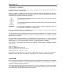
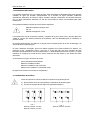
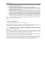
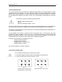
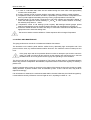
SVA
INSTALACIÓN, MONTAJE Y MANTENIMIENTO
INSTALLATION, ASSEMBLY AND MAINTENANCE
Bombas Ideal, S.A.
2
INDICE
INDEX
PAGINA
1.
2.
3.
4.
5.
6.
7.
8.
9.
PREÁMBULO – GARANTIA.......................................................................................
RECEPCIÓN .............................................................................................................
DESCRIPCIÓN DEL GRUPO …………………………………………………………….
CONEXIONADO ELÉCTRICO ..................................................................................
CONTROL Y MANTENIMIENTO ..............................................................................
ANOMALIAS DE FUNCIONAMIENTO ......................................................................
SECCIÓN Y LISTA DE COMPONENTES .................................................................
DIAGRAMA CONEXION ...........................................................................................
INSTALACION TIPO ..................................................................................................
3
3
3
4
4
5
9
10
11
PAGINA
1.
2.
3.
4.
5.
6.
7.
8.
9.
INTRODUCTION AND WARRANTY .........................................................................
ACCEPTANCE ..........................................................................................................
GROUP DESCRIPTION ............………………………………………………………….
ELECTRIC CONNECTIONS .....................................................................................
CONTROL AND MAINTENANCE .............................................................................
TROUBLESHOOTING …………...............................................................................
SECTION AND COMPONENTS LIST …...................................................................
CONEXION DIAGRAM ...............................................................................................
INSTALLATIONS
TYPE...............................................................................................
6
6
6
7
7
8
9
10
11
Bombas Ideal, S.A.
1. PREAMBULO – GARANTIA
Este manual de servicio está dirigido a los usuarios de bombas SVA. Contiene las instrucciones de
instalación, servicio y mantenimiento.
Antes de proceder a cualquier tipo de intervención, el usuario debe leer atentamente este manual y
prestar atención a cuantas sugerencias y recomendaciones se den en él, especialmente las que sean
precedidas de los siguientes símbolos de seguridad:
La no observancia de estas instrucciones, puede exponer a las personas a riesgos
importantes para su salud.
La no observancia de estas instrucciones, puede exponer a las personas a riesgos
de origen eléctrico.
ATENCIÓN
Las instrucciones identificadas con este mensaje, indican su importancia para una
correcta instalación, utilización y mantenimiento.
Las instrucciones contenidas en este manual cumplen con la Directiva de la CEE sobre Máquinas
nº89/399, así como sus sucesivas modificaciones.
Con el objeto de mejorar el resultado final de sus productos, Bombas Ideal S.A. se reserva el derecho
de modificar el contenido del presente manual y/o el propio producto sin necesidad de avisar
previamente a sus clientes.
El incumplimiento de las sugerencias y recomendaciones de este manual, así como la incorrecta
utilización o la manipulación no autorizada del producto, invalida totalmente la responsabilidad de
Bombas Ideal S.A., por los posibles daños causados, ya sean personales o materiales.
Ante cualquier duda respecto del producto, su utilización, mantenimiento o reparación deberán
contactar con;
Bombas Ideal S.A.
Polig. Ind. Mediterráneo C/Cid nº 8
Tfno. 34 961 402 143 Fax 34 961 402 131
46560 Massalfassar – Valencia – Spain
El manual se suministra junto con la bomba y debe estar próximo al lugar de la instalación,
debidamente protegido, para que pueda ser consultado por los usuarios en caso de necesidad.
2. RECEPCIÓN
En el momento de la recepción del material que compone la expedición se comprobará si los materiales
han sufrido algún desperfecto, en especial el cable de alimentación. Hacer recuento de los mismos y
notificar la existencia de cualquier anomalía.
Si el grupo debe permanecer algún tiempo en almacén convendrá colocarlo en un lugar seco. Después
de un largo período de inactividad, tanto en almacén como en el lugar de trabajo, girar el rodete a mano,
por si hubiera algún proceso de agarrotamiento por oxidación.
3
Bombas Ideal, S.A.
4
3. DESCRIPCION DEL GRUPO
Las bombas sumergidas SVA con rodete de hélice están especialmente diseñadas para elevar grandes
caudales de agua. Se emplean ventajosamente en el bombeo de aguas pluviales, estaciones
depuradoras, desecación de terrenos, riegos, arrozales, drenajes, refrigeración de centrales eléctricas,
etc. Los altos rendimientos obtenidos por este tipo de bombas las hacen recomendadas para estas
instalaciones.
Es importante respetar los límites de funcionamiento siguientes:
Máxima temperatura del agua 40ºC
PH: 5-9
Máxima sumergencia: 10 mts.
Las bombas SVA son de construcción robusta y compacta de eje único entre motor y bomba, dando una
solidez al conjunto que elimina problemas de instalación. Han sido diseñadas para su instalación en
posición vertical.
El montaje resulta sencillo, al ir fijada por su propio peso e instalada dentro de un tubo de descarga o en
cámara de obra civil de hormigón.
El motor, totalmente sumergido, forma una unidad compacta con la parte hidráulica. Es trifásico, con
protección IP 68 y aislamiento clase F, para 155º C. El eje del rotor gira sobre cojinetes de bolas
lubricados permanentemente, libre de mantenimiento. La estanqueidad del eje entre el motor y la parte
hidráulica se consigue por medio de dos cierres mecánicos de alta calidad y una cámara de aceite
intermedia.
Se incorporan en el grupo funciones de control:
-
Control temperatura del bobinado
Detector humedad en estator
Detector humedad en caja conexiones
Detector de humedad en la cámara del aceite
El esquema de conexión se muestra en el apartado 8.
4. CONEXIONADO ELECTRICO
Antes de la puesta en marcha se deberá comprobar los siguientes puntos:
a) Que la tensión de la red corresponde a la indicada en la placa del grupo.
b) En caso de arranque directo según los siguientes esquemas.
Z
X
Y
Z
X
Y
U
V
W
U
V
W
FIG. 1
Bobinado 230/400 red 230V
Bobinado 400/690 red 400V
FIG. 2
Bobinado 230/400 red 400V
Bombas Ideal, S.A.
c)
En el caso de arranque estrella - triángulo, del motor salen 2 cables que habrá que conectar
adecuadamente al cuadro de maniobras.
d) En todos los casos se conectará el cable de toma de tierra para evitar accidentes.
e) Control de temperatura del estator: El sensor térmico que lleva el bobinado incorporado protege
el estator de sobrecalentamiento en casos como prolongado funcionamiento en seco, excesiva
temperatura en el medio bombeado, etc.
f) Detección de humedad. En la cámara del aceite, caja de conexiones e interior motor se coloca
un electrodo que asegura la estanqueidad, detectando la presencia de humedad. La resistividad
normal es ≥ 100 KΩ, en caso de entrada agua o humedad, la resistividad cae hasta ser ≤ 30KΩ
g) Control de temperatura de los rodamientos (opcional): Los sensores térmicos de los rodamientos
los protegen ante sobrecalentamiento en casos como falta de lubricación, rodamientos dañados,
excesiva temperatura en el medio bombeado, etc. Convendrá asegurarse que los fusibles o relé
de sobrecorriente montados y regulados son los adecuados para soportar la carga de arranque.
Se verificará el sentido de giro del grupo, cambiando las fases de conexión en el cuadro en caso
de que lo haga en sentido contrario.
5. CONTROL Y MANTENIMIENTO
El funcionamiento del grupo debe ser silencioso y sin vibraciones.
Se observará en los amperímetros del cuadro eléctrico cualquier consumo anormal y en caso de que así
sea se buscarán las posibles causas. El número máximo de arranques por hora es de 6.
Si el grupo se para y al intentar ponerlo en marcha la protección se dispara es conveniente no
insistir, averiguar las causas y subsanarlas adecuadamente, pero nunca forzar al grupo a
trabajar en tales condiciones.
El mantenimiento de los grupos SVA es prácticamente nulo, salen de fábrica perfectamente preparados
para su inmediata utilización sin necesidad de manipulación. No obstante para asegurar una larga
duración de la bomba se recomienda comprobaciones e inspecciones regulares.
Será importante observar el estado de las juntas tóricas, pues como elementos de cierre estático deben
estar en perfectas condiciones. Al menor indicio de defecto deben ser sustituidas.
Si se observara disminución en la cantidad de aceite o presencia de agua se procederá a la revisión de
los cierres mecánicos para comprobar su estanqueidad. Una vez comprobado se repondrá el aceite que
deberá tener una viscosidad entre 3 y 6 grados Engler a 50º C, equivalente a un SAE 10 - 20.
5
Bombas Ideal, S.A.
6
6. ANOMALÍAS DE FUNCIONAMIENTO
ANOMALIA
1. El grupo no arranca.
CAUSA
1.1 No hay tensión en la red.
1.2 Fusible fundido.
1.3 Cable cortado.
1.4 Bomba agarrotada.
2. El grupo arranca pero no
2.1 Giro contrario.
eleva agua.
2.2 Altura real mayor que la de la
bomba.
2.3 Rodete atascado.
3. Caudal insuficiente.
3.1 Giro contrario.
3.2 Tubo descarga obstruido.
3.3 Rodete parcialmente atascado.
3.4 Desgaste de rodete.
4. Intensidad absorbida
4.1 Bomba frenada.
superior a la prevista.
4.2 Tensión red baja.
4.3 Tensión de red inferior a la
indicada en la placa.
5. Agua en la caja de
5.1 Juntas deterioradas.
conexiones motor.
5.2 Rotura del recubrimiento del
cable.
6. Agua o aceite en la carcasa 6.1 Cierre mecánico superior
del motor.
deteriorado.
6.2 Juntas tóricas carcasa
estropeadas.
7.Agua en el aceite del
7.1 Cierre mecánico inferior
depósito.
deteriorado.
7.2 Tapones de llenado y vaciado
mal apretados o juntas rotas.
7.3 Juntas tóricas estropeadas.
SOLUCION
1.1 Averiguar si hay fluido.
1.2 Reponer fusible.
1.3 Reparar cable.
1.4 Soltar bomba.
2.1 Invertir el giro.
2.2 Cambiar el tamaño bomba.
2.3 Desatascar el rodete.
3.1 Invertir el giro.
3.2 Limpiar tubo.
3.3 Limpiar rodete.
3.4 Cambiar rodete.
4.1 Soltar la bomba.
4.2 Elevar la tensión en red.
4.3 Cambio del tipo de grupo.
5.1 Reponer juntas.
5.2 Reparar cable o cambio por
uno nuevo.
6.1 Cambiar cierre mecánico.
6.2 Poner juntas nuevas
(reponer aceite).
7.1 Cambiar cierre mecánico.
7.2 Apretar tapones y cambiar
juntas.
7.3 Poner juntas nuevas
(reponer aceite).
Bombas Ideal, S.A.
1. INTRODUCTION AND WARRANTY
This service manual is intended for users of SVA pumps. It contains the instructions for installation,
service and maintenance.
Before proceeding to do any kind of work on the equipment, users should read this manual carefully and
pay attention to any suggestions and tips given in it, particularly the ones preceded by the following safety
symbols:
Failure to observe these instructions may expose people to serious danger for their
health.
Failure to observe these instructions may expose people to electrical risks.
TAKE NOTE
Any instructions preceded by this message are of great importance for proper installation,
use and maintenance.
The instructions contained in this manual comply with EEC directive nº89/399 on machines, as well as
its subsequent modifications.
In order to improve the final result of its products, Bombas Ideal S.A. reserves the right to modify the
content of this manual and/or the product itself with no need to inform its customers beforehand.
Failure to comply with the suggestions and recommendations in this manual, as well as improper use
or non-authorised handling of the product, shall fully release Bombas Ideal S.A. from any liability as
regards possible damage caused, whether this be personal or material.
In the event of any doubt about the product, its use, maintenance or repair, please contact;
Bombas Ideal S.A.
Polig. Ind. Mediterráneo C/Cid nº 8
Tel. 34 961 402 143 Fax 34 961 402 131
46560 Massalfassar – Valencia – Spain
The manual is supplied along with the pump and should be kept close to the point of installation, duly
protected so that this can be consulted by users when required.
2. ACCEPTANCE
Check that the packing and shipping materials have not been damaged in transit, specially the inlet cable.
Make a report of any such damage and notify any irregularities at once.
If the pump is to be stored for any length of time, it must be kept in a dry place. The impeller of the pump
must be rotated by hand after a long period of being out of active service, to detect seizing due to
oxidation.
7
Bombas Ideal, S.A.
8
3. GROUP DESCRIPTION
The SVA submersible pumps, provided with propeller/helicoidal impeller, are expressly designed for lifting
considerable flow rate capacities. They are extremely suitable for pumping rainfall deposits, purifying
stations, ground drying, irrigations, rice fields, waste drains, power plant cooling systems, etc. Thanks to
the high efficiencies obtained by this kind of pump, they are particularly recommended for the above
plants.
It’s important to observe the following operational limits:
Maximum water temperature 40ºC.
PH: 5-9
Maximum submergence depth : 10 mts.
The SVA pumps have strong and compact structure and are provided with single motor – pump shaft, thus
giving a very solid unit with easy installation. SVA pumps have been designed for vertical installation.
The erection is quite simple, as the pump is fixed by its own weight and installed inside a waste piping or in
a concrete civil work chamber.
The submersible motor makes a compact unit with the hydraulic part. It is three phase, have IP68
protection and Class F insulation for use up to 155º C. The rotor shaft rotates on free-maintenance ball
bearings permanently lubricated. A set of high quality mechanical seals, operating in an oil bath and
situated between the pump and the motor, brings about complete leak-tightness.
Following control functions are incorporated in the unit:
- Winding control temperature.
- Humidity sensor on stator
- Humidity sensor on connexion box
- Humidity sensor on oil bath.
The connexion diagram is showed in chapter 8.
4. ELECTRIC CONNECTIONS
Prior to starting the following points shall be duly verified:
a) The mains voltage is exactly the same as that stated on the group plate.
b) In case of a direct start, as show in the figs. 1 and 2
Z
X
Y
Z
X
Y
U
V
W
U
V
W
FIG. 1
Winding 230/400 network 230V
Winding 400/69 0 network 400V
FIG. 2
Winding 230/400 network 400V
Bombas Ideal, S.A.
c) In case of a star-delta start, there are two cables leaving the motor which shall appropriately
connect to the control panel.
d) In every case the ground connection shall be connected in order to avoid any undue accidents.
e) Temperature control in the stator: the stator is protected by a thermal sensor incorporated in the
motor to protect against overheating due to dry running, high temperature in the fluid, etc.
f) Humidity sensor: On the oil bath, connexion box, and motor chamber one electrode is placed to
control the leak-tightness. Normal resistivity is ≥100 KΩ, in case of water entrance or humidity,
the resistivity drops down to ≤ 30KΩ.
g) Temperature control in ball bearings (under request): Ball bearings thermal gauges protect
against overheating due to loss of grease, bearing damage, high temperature in the fluid, etc.
h) It shall be verified whether the fuses and relays of overcurrent mounted and adjusted are the
appropriate ones to stand the starting load.
The sense of rotation must be verified too. Phase sequence will be changed if requested.
5. CONTROL AND MAINTENANCE
The group performance must be in a noiseless and vibration-free manner.
The ammeters on the electric panel shall be verified for any abnormally high consumption and if this
proves to be the case, any eventual reasons shall be found out. The maximum number of starts per hour
is six.
If the group stops and the its protection blows out when an attempt to put it back to service is
made, you shall not insist at all but just find out the reasons and overcome them in the best
possible manner as it is not good to force the group into operating in such conditions.
The SVA groups call for practically no maintenance. They leave our plant ready for immediate utilization
without any previous manipulation. Nevertheless, inspections shall be carried out regularly to warranty a
perfect work.
Another important point to keep in mind here is the status of the relevant O’rings since as they are static
sealing elements, a perfect condition must be exhibited by them. If this is not the case, they shall be
replaced accordingly.
If an oil reduction is observed, the mechanical seals shall be checked. After that, the oil shall be topped up.
It must exhibit a viscosity of between 3 and 6º Engler at 50º C, equalling to a SAE 10 – 20.
9
Bombas Ideal, S.A.
10
6. TROUBLESHOOTING
TROUBLE
1. The group does not start
CAUSE
1.1 No voltage on mains line
1.2 Blown out fuse
1.3 Cut off cable
1.4 Seized pump
2. The group starts, but it does 2.1 Opposite turning
not lift water
2.2 Real height is higher than of the
pump
2.3 Jammed impeller
3. Not a large enough flow
3.1 Opposite turning
rate.
3.2 Clogged discharge tube
3.3 Semi-jammed impeller
3.4 Impeller
4. Absorbed intensity higher
4.1 Braked pump
than envisaged one
4.2 Low mains voltage
4.3 Mains voltage lower than that
stated on the plate
5. There is water in the motor 5.1 Damaged joints
connecting box
5.2 Broken cable coating
6. There is water or oil in the
motor carcass
6.1 Damaged upper mechanical
seal
6.2 Carcass O’rings damaged
7. There is water in the oil tank 7.1 Damaged lower mechanical seal
7.2 Filling and emptying closures
poorly tightened or broken joints
7.3 Damaged O’rings
SOLUTION
1.1 See whether electric current
1.2 Replace fuse
1.3 Repair cable
1.4 Release pump
2.1 Reverse turning
2.2 Change the pump size
2.3 Unjam impeller
3.1 Reverse turning
3.2 Clean tube
3.3 Clean the impeller
3.4 Change impeller.
4.1 Release pump
4.2 Increase mains voltage
4.3. Change of group type
5.1 Replace joints
5.2 Repair cable or replace it with
a new one
6.1 Replace mechanical seal
6.2 Place fresh O’rings (top up oil)
7.1 Replace mechanical seal
7.2 Tighten closures and replace
joints
7.3 Place new O’rings (top up oil)
Bombas Ideal, S.A.
11
7. SECCION Y LISTA DE COMPONENTES / SECTION AND COMPONENTS LIST
Prensa cable completo
Complete stuffing box
Sensor de humedad
Leakage sensor
Estator
Stator
Sensor de humedad
Leakage sensor
Cierre mecánico sup.
Upper Mech. seal
Asa
Handle
Caja de conexiones
Conexion box
Rodamiento superior
Upper bearing
Eje
Shaft
Rotor
Rodamiento inferior
Lower bearing
Cuerpo de bomba
Bowl assembly
Cierre mecánico inf.
Lower Mech. seal
Rodete
Propeller
Cuerpo aspiración
Suction case
Bombas Ideal, S.A.
12
8. DIAGRAMA DE CONEXION / CONEXION DIAGRAM
PE
L1
L2
L3
N
U
V
W
TT
M
Motor
TERMINAL CONTROL
CONTROL TERMINAL
N. 11 (ó 21)
N. 12 (ó 22)
N. 13 (ó 23)
N. 31
N. 32
N. 41
N. 71
N.95
N.96
TT : Toma de tierra / earthing
N. 11: Sensor temperatura (salida) / Overheat protection terminal (outlet)
N. 12: Sensor temperatura (entrada) (común para N.11 , 13) / Overheat protection
terminal (inlet) (common for N.11, 13)
N. 13: Sensor temperatura (salida, standby) / Overheat protection terminal (outlet,
standby)
N. 31: Sensor de humedad cámara aceite / Leakage sensor terminal for oil chamber
N. 32: Entrada común para N.31, 41, 71. Common inlet for N.31,41,71)
N. 41: Sensor de humedad caja conexiones / Leakage sensor for junction box
N. 71: Sensor de humedad cámara motor / Leakage sensor for motor chamber.
N.95 N.96 : Resistencia anticondensación (230V/ Monofasico / 50Hz) / Anticondensation heating (230V /Single phase/ 50 Hz).
Bombas Ideal, S.A.
13
9 INSTALACION TIPO / INSTALLATION TYPE
DESCRIPCION / DESCRIPTION
1
2
3
4
5
6
7
8
9
10
11
12
13
14
15
16
17
VALVULA
TUBERIA IMPULSIÓN
CABEZAL DESCARGA
PERFIL HORIZONTAL
CUBIERTA
ESLINGA DE IZADO
TENSOR
CABLE ACERO
CLIP CABLE
TORNILLO ANCLAJE
AMARRE CABLE ACERO
BOMBA
SEGURO ANTI-GIRO
JUNTA TORICA
EMPAQUETADURA
PRENSA CABLE
CAJA PRENSA CABLE
VALVE
DISCHARGE PIPING
DISCHARGE HEAD
HORIZONTAL BEAM
COVER
LIFTING ROPE
TURNBUCKLE
STEEL CABLE
CABLE CLIP
ANCHORING POINT
CABLE FIXING
PUMP
ROTATION STOPPER
O’RING
PACKING
GLAND
PACKING BOX