1
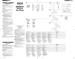
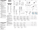
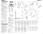
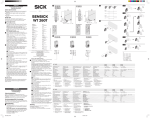
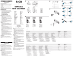
A
ENGLISH
Photoelectric Proximity Switch
with infrared light
Operating Instructions
Safety Specifications
‡ Read the operating instructions before starting operation.
‡ Connection, assembly, and settings only by competent
technicians.
‡ Protect the device against moisture and soiling when
operating.
‡ No safety component in accordance with EU machine
guidelines.
8 008 964.1202 GO KE
Proper Use
2
3
4
Maintenance
WTR2-P511 S01
WTR2-P511 S03
WTR2-P521 S04
FR
WTR (n-1)
We reserve the right to make changes without prior notification
Änderungen vorbehalten
Angegebene Produkteigenschaften und technische Daten
stellen keine Garantieerklärung dar
Sous réserve de modifications
Reservam-se alterações
Ret til ændringer forbeholdes
Con riserva di modifiche
Wijzigingen voorbehouden
Reservado el derecho a introducir modificaciones
2
DEUTSCH
‡ Vor der Inbetriebnahme die Betriebsanleitung lesen.
‡ Anschluss, Montage und Einstellung nur durch Fachpersonal.
‡ Gerät bei Inbetriebnahme vor Feuchte und Verunreinigung
schützen.
‡ Kein Sicherheitsbauteil gemäß EU-Maschinenrichtlinie.
4
WTR zwischen den Rollen an geeignete Halter unter
Förderniveau anschrauben (z.B. SICK-Haltewinkel). Dabei
Tastweite TW (A), Förderrichtung, Abstrahlwinkel (5o),
Abstand zum Fördergut (B)/Blindbereich beachten.
Nur WTR 2-P 521/-N 551/-P 521 S04/-N 551 S05:
D: dunkelschaltend, bei Lichtunterbrechung (Objekt nicht
vorhanden) Ausgang (-P 521, -P 521 S04: QP, -N 551,
–
–
-N 551 S05, -N 551 S06: QN, -P 551 S08: QP) aktiv;
Nur WTR 2-P 511/-N 551/-P 511 S03/-P 511 S01/
-N 551 S05:
L: hellschaltend, bei Lichtempfang (Objekt vorhanden)
Ausgang (-P 511, -P 511 S01, -P 511 S03, -P 551 S08: QP, N 551 S05, -N 551: QN) aktiv.
Einsatzbedingungen wie Tastweite, Objektgröße und
Remissionsvermögen des Tastgutes sowie des Hintergrundes überprüfen und mit der Kennlinie im Diagramm
vergleichen. (x=Tastweite, y=Übergangsbereich zwischen
eingestellter Tastweite und sicherer Hintergrundausblendung (z) in % der Tastweite, Ro=Remission Objekt,
Rh=Remission Hintergrund).
Remission: 6%=schwarz, 18%=grau, 90%=weiß (bezogen
auf Standardweiß nach DIN 5033).
Justage Lichtempfang:
Tastweite auf Max. stellen.
Objekt positionieren. Lichtfleck auf Objekt ausrichten.
Empfangsanzeige muss leuchten. Leuchtet sie nicht, WTR
neu justieren, reinigen bzw. Einsatzbedingungen überprüfen.
Einstellung Tastweite:
Objekt entfernen, die Empfangsanzeige muss erlöschen.
Leuchtet sie weiterhin, Drehknopf in Richtung Min. drehen,
bis sie erlischt. Drehknopf auf Min. stellen. Objekt
positionieren. Drehknopf in Richtung Max. drehen, bis die
Empfangsanzeige aufleuchtet.
Nur WTR 2-P621/-P621 S02:
1,5 m lange Leitung zum Anschluss eines separat in der
Förderanlage montierten Ventils (Schaltstrom 600 mA).
Die integrier te Logik erlaubt einen kontrollierten Stauvorgang an definierten Stauplätzen.
Einzeleinlauf: Fördergut durchläuft den gesamten Einlaufbereich und wird erst am WTR (n) gestoppt. Sind zwei
benachbarte Stauplätze belegt, dann wird das Fördergut
gestoppt: Lückenbildung zwischen den Fördergütern.
Bestimmungsgemäße Verwendung
Wartung
Der WTR ist ein optoelektronischer Sensor mit Logik und
Ventilanschlussmöglichkeit oder ohne Logik/Ventilanschlussmöglichkeit, der zum berührungslosen Erfassen von Gegenständen auf Förderrollen und zur Steuerung der Stauplätze
eingesetzt wird.
SICK-Lichttaster sind wartungsfrei. Wir empfehlen, in regelmäßigen Abständen
- die optischen Grenzflächen zu reinigen,
- Verschraubungen und Steckverbindungen zu überprüfen.
Inbetriebnahme
1
Leitungsdose spannungsfrei aufstecken und festschrauben.
Für Anschluss in B gilt: brn=braun, blu=blau, blk=schwarz,
wht=weiß; FR = Förderrichtung.
Nur WTR 2-P621/WTR 2-P621 S02:
WTR an Betriebsspannung legen (s. Typenaufdruck).
Stromversorgung für weitere WTR:
Leitungsdose des ersten Gerätes mit dem Gerätestecker
des jeweiligen nächsten WTR verbinden. Die Leitungsdose
des WTR (n) bleibt unverbunden.
2
*
3
Sicherheitshinweise
3
WTR 2-P621 S02
B
SICK photoelectric switches do not require any maintenance.
We recommend that you clean the optical interfaces and check
the screw connections and plug-in connections at regular
intervals.
Reflexions-Lichttaster
mit unsichtbarem Infrarotlicht
Betriebsanleitung
1
WTR 2-P621
521/621
Starting Operation
Connect and secure cable receptacle tension-free.
The following apply for connection in B: brn=brown,
blu=blue, blk=black, wht=white; FR = conveyor direction.
WTR 2-P621/WTR 2-P621 S02 onl
y:
only:
Connect WTR to operating voltage (see type label). Power
supply for additional WTR:
Connect the cable receptacle of the first device with the
equipment plug of the respective next WTR. The cable
receptacle of the last WTR (n) is not connected to
anything.
Mount the WTR with the mounting holes between the
rollers at the suitable bracket below the conveyor level
(e.g., SICK mounting bracket). Pay attention to the scanning
distance (A), conveyor direction, angle of dispersion (5o)
and the distance to conveyed products (B)/blind area.
WTR 2-P 521/-N 551/-P 521 S04/-N 551 S05 onl
y:
only:
D: dark-switching, if light interrupted (object not present),
output (-P 521,
– P, -N 551, -N 551 S05,
– -P 521 S04: Q
-N 551 S06: QN, -P 551 S08: QP) active;
WTR 2-P 511/-N 551/-P 511 S03/-P 511 S01/
-N 551 S05 onl
y:
only:
L: light-switching, if light received (object present), output
(-P 511, -P 511 S01, -P 511 S03, -P 551 S08: QP,
-N 551 S05, -N 551: QN) active.
Check application conditions such as scanning distance, size
and reflectance of object to be detected as well as of
background, and compare with characteristic in diagram.
(x=scanning distance, y=transition range between set
scanning distance and reliable background suppression (z)
in % of scanning distance, Ro=reflectance of object,
Rh=reflectance of background).
Reflectance: 6%=black, 18%=gray, 90%=white (based on
standard white to DIN 5033).
Adjustment of light reception:
Set scanning distance to max.
Position object. Position light spot on object. Signal strength
indicator should light up. If it does not light up, readjust
and/or clean WTR and/or check application conditions.
Setting scanning distance:
Remove object, signal strength indicator should go out. If it
does not go out, turn switch towards min. until it goes out.
Set switch to min. Position object. Turn switch towards max.
until signal strength indicator lights up.
WTR 2-P621/-P621 S02 onl
y:
only:
1.5 m long cable for connecting a valve mounted separately
in the system (switching current 600 mA).
The integrated logical device enables a controlled backup
procedure at defined backup spots.
Single feed: Conveyed product runs through the complete
feeder area and is only stopped at WTR (n). If two
neighboring backup spots are occupied, the conveyed
product is stopped: A gap is created between the
conveyed products.
2-P521
2-P511
2-P511 S07
2-P551 S08
2-N551
2-N551 S05
2-N551 S06
WTR 2
The WTR is an opto-electronic sensor with a logic device and
a valve connection option or without a logic device and a valve
connection option. It is used for contactless detection of
objects on conveyor belts and for controlling backup spots
(WTR 2-P621, WTR 2-P621 S02).
1
WTR
WTR
WTR
WTR
WTR
WTR
WTR
Alarm
WTR (1)
4
FRANÇAIS
Détecteur réflex
avec rayons infrarouge
Instructions de Service
Conseils de sécurité
‡ Lire les Instructions de Service avant la mise en marche.
‡ Installation, raccordement et réglage ne doivent être
effectués que par du personnel qualifié.
‡ Lors de la mise en service, protéger l’appareil de l’humidité
et des saletés.
‡ N’est pas un composant de sécurité au sens de la directive
européenne concernant les machines.
Utilisation correcte
Le WTR est un capteur optoélectronique à logique et
possibilité de raccorder une vanne ou bien sans logique ni
possibilité de raccorder une vanne, et s’utilise pour la détection
sans contact des objets défilant sur des convoyeurs à rouleaux
par gravité et pour le pilotage des aires d’accumulation
(WTR 2-P621, WTR 2-P621 S02).
2
Mise en service
1
2
3
4
Enficher la boîte à conducteurs sans aucune tension et la
visser.
Pour le raccordement dans B on a: brn=brun, blu=bleu,
blk=noir, wht=blanc; FR = direction de convoyage.
WTR 2-P621/WTR 2-P621 S02 uniquement: Appliquer
la tension de service au capteur WTR (voir inscription
indiquant le modèle). Alimentation électrique d’autres
capteurs WTR: Raccorder la boîte à câbles du premier
appareil à la fiche d’entrée du capteur suivant respectif. La
boîte à câbles du nième WTR (n) reste non connectée.
Monter le capteur WTR au moyen de ses trous de fixation
sur des supports appropriés (par ex. équerre de fixation
SICK) entre les rouleaux, sous le niveau de convoyage. Ce
faisant, tenir compte de la distance de détection TW (A),
direction de convoyage, angle de rayonnement (5o),
distance à l’objet convoyé (B) ou champ sans visibilité.
WTR 2-P 521/-N 551/-P 521 S04/-N 551 S05
uniquement: D: commutation sombre, la sortie
– (-P 521, -P
521 S04: QP,–-N 551, -N 551 S05, -N 551 S06:QN,
-P 551 S08: QP) est active lorsque le trajet lumineux est
interrompu (pas d’objet présent);
WTR 2-P 511/-N 551/-P 511 S03/-P 511 S01/
-N 551 S05 uniquement: L: commutation claire, la sor tie
(-P 511, -P 511 S01, -P 511 S03, -P 551 S08: QP,
-N 551 S05, -N 551: QN) est active à la réception de
lumière (objet présent).
Vérifier les conditions d’utilisation telles que distance de
détection, taille de l’objet, facteur de luminance du matériel
à détecter et de l’arrière-plan, et les comparer à la courbe
caractéristique du diagramme. (x=distance de détection,
y=plage de transition entre la distance de détection ajustée
et une élimination certaine de l’arrière-plan (z) en % de la
distance de détection, Ro=luminance objet, Rh=luminance
arrière-plan). Luminance: 6%=noir, 18%=gris, 90%=blanc
(par rapport au blanc étalon selon DIN 5033).
Ajustement Réception de la lumière:
Régler la distance de détection sur Maxi.
Positionner l’objet. Pointer la tache lumineuse vers l’objet.
Le témoin de réception doit rester allumé en permanence.
S’il n’est pas allumé, nettoyer ou ajuster à nouveau le
détecteur WTR, ou vérifier les conditions d’utilisation.
Réglage Distance de détection: Enlever l’objet, le témoin de
réception doit s’éteindre. Si le témoin reste allumé, tourner
le bouton rotatif en direction Mini jusqu’à ce qu’il s’éteigne.
Mettre le bouton rotatif en position Mini. Positionner
l’objet. Tourner le bouton rotatif en direction Maxi jusqu’à
ce que le témoin de réception s’allume.
WTR 2-P621/-P621 S02 uniquement:
Câble de 1,5 m de long pour le raccordement d’une vanne
montée séparément dans l’installation (Courant de
commutation 600 mA).
La logique intégrée permet une accumulation contrôlée sur
des aires d’accumulation définies.
Entrée individuelle: le matériel convoyé traverse toute la
zone d’entrée et est stoppé seulement au détecteur WTR
(n). Si deux aires d’accumulation voisines sont occupées,
matériel convoyé est stoppé: formation d’une lacune entre
les objets convoyés.
Maintenance
3
4
Manutenção
Os sensores de luz SICK não requerem manutenção.
Recomendamos que se faça, em intervalos regulares,
- a limpeza das superfícies óticas,
- e um controle às conexões roscadas e uniões de conetores.
4
SICK-fotoceller kræver ingen vedligeholdelse. Vi anbefaler, at
- de optiske grænseflader rengøres
- forskruninger og stikforbindelser kontrolleres med
regelmæssige mellemrum.
Instruções de segurança
‡ Antes do comissionamento dev ler as instruções de
operação.
‡ Conexões, montagem e ajuste devem ser executados
exclusivamente por pessoal devidamente qualificado.
‡ Guardar o aparelho ao abrigo de umidade e sujidade.
‡ Não se trata de elemento de segurança segundo a Diretiva
Máquinas da União Europêa.
2
Utilização devida
O WTR é um sensor optoelectrónico com parte lógica e
possibilidade de conexão de válvula ou sem parte lógica/sem
possibilidade de conexão de válvula, utilizado para detectar,
sem contacto, objectos sensores em rolos de transpor te e para
controlo de pontos de acumulação (WTR 2-P621,
WTR 2-P621 S02).
Comissionamento
Enfiar a caixa de cabos sem torções e aparafusá-la.
Para a ligação elétrica em B é: brn=marron, blu=azul,
blk=preto, wht=branco; FR = o sentido de transporte.
Só WTR 2-P621/WTR 2-P621 S02: Colocar o sensor na
tensao de serviço (ver letreiro de tipo).
Alimentação de corrente para outros WTR.
3
Gebruik volgens bestemming
De WTR is een opto-elektronische sensor met logica en een
ventielaansluitmogelijkheid of zonder logica/ventielaansluitmogelijkheid die voor het contactloos registreren van een
object op transpor trollen en voor het sturen van stuwplaatsen
(WTR 2-P621, WTR 2-P621 S02) wordt toegepast.
Avvertimenti di sicurezza
‡ Leggere prima della messa in esercizio.
‡ Allacciamento, montaggio e regolazione solo da par te di
personale qualificato.
‡ Durante la messa in esercizio proteggere da umidità e
sporcizia.
‡ Non componente di sicurezza secondo la Direttiva macchine
EN.
2
Impiego conforme allo scopo
Il WTR è un sensore optoelettronico dotato di logica
elettronica e collegamento per valvola oppure senza logica
elettronica e collegamento per valvola che viene usato per il
rilevamento senza contatto di oggetti su nastri di
convogliamento e per il comando di aree di magazzinaggio
(WTR 2-P621, WTR 2-P621 S02).
Messa in esercizio
1
Beregnet anvendelse
PORTUGUÊS
‡ Lees voor de ingebruikneming de gebruiksaanwijzing.
‡ Aansluiting, montage en instelling alleen door vakbekwaam
personeel laten uitvoeren.
‡ Apparaat voor ingebruikneming tegen vocht en
verontreiniging beschermen.
‡ Geen veiligheidscomponent conform EU-machinerichtlijn.
ITALIANO
‡ Driftsvejledningen skal gennemlæses før idrifttagning.
‡ Tilslutning, montage og indstilling må kun foretages af fagligt
personale.
‡ Apparatet skal beskyttes mod fugtighed og snavs ved
idrifttagningen.
‡ Ingen sikkerhedskomponent iht. EU-maskindirektiv.
Foto-célula de reflexão
com luz infra-vermelha
Instruções de operação
Veiligheidsvoorschriften
Sensore luminoso a riflessione
con luce infrarossa
Instruzioni per l'uso
Sikkerhedsforskrifter
Ledningsdåse monteres spændingsfri og skrues fast.
For tilslutning i B gælder : brn=brun, blu=blå, blk=sort,
wht=hvid; FR = transpor tretningen.
Kun WTR 2-P621/WTR 2-P621 S02:
WTR tilsluttes driftsspænding (se Typeskilt).
Strømforsyning til yderligere WTR:
Ledningsdåsen fra det første apparat forbindes med
apparatstikket fra den næste sensor. Ledningsdåsen fra den
n-te WTR forbliver uforbundet.
Sensoren monteres på egnede holdere under
transportniveauet over befæstelsesboringerne mellem
rullerne (f.eks. på SICK-vinkelbeslag). Derved skal man være
opmærksom på aftastningsvidden TW (A),
transportretningen, strålingsvinklen (5o), afstanden til det
transporterede materiale (B)/det blinde område.
Kun WTR 2-P 521/-N 551/-P 521 S04/-N 551 S05:
D: bliver mørk, ved lysafbrydelse (uden objekt) udgang (-P
521, -P 521 S04:
– QP, -N 551, -N
– 551 S05,
-N 551 S06: QN, -P 551 S08: QP) aktiv;
Kun WTR 2-P 511/-N 551/-P 511 S03/-P 511 S01/
-N 551 S05: L: bliver lys, ved lysmodtagelse (med objekt)
udgang (-P 511, -P 511 S01, -P 511 S03,
-P 551 S08: QP, -N 551 S05, -N 551: QN) aktiv.
Anvendelsesbetingelser som f.eks. tastevidde,
objektstørrelse og remissionsevne for tasteproduktet samt
for baggrunden kontrolleres og sammenlignes med
karakteristikken i diagrammet. (x=tastevidde,
y=overgangsområde mellem indstillet tastevidde og sikker
baggrundsudtoning (z) i % af tastevidden. Ro=remission
objekt, Rh=remission baggrund).
Remission: 6%=sort, 18%=grå, 90%=hvid (fastlagt på basis
af standardhvid iht. DIN 5033).
Indstilling lysmodtagelse: Tastevidde stilles på max.
Objekt positioneres. Lysplet rettes på objekt.
Modtagerlampe skal lyse. Lyser den ikke, justeres lystaster
WTR igen, rengøres eller anvendelsesbetingelser
kontrolleres.
Indstilling tastevidde:
Objekt fjernes, modtagerlampen skal slukke. Bliver den ved
med at lyse, drejes drejeknappen i retning min., indtil den
Reflectie-fotocel
met infraroodlicht
Gebruiksaanwijzing
1
DANSK
1
NEDERLANDS
2
Ingebruikneming
Reflektions-lystaster
med infrarød lys
Driftsvejlening
WTR er en opto-elektronisk sensor med logik og mulighed for
tilslutning af en ventil eller uden logik/mulighed for tilslutning af
en ventil, den benyttes til berøringsløs registrering af objekter
på transportruller og til styring af ophobnings-pladserne
(WTR 2-P621, WTR 2-P621 S02).
slukker. Drejeknap stilles på min. Objekt positioneres.
Drejeknap drejes i retning max., indtil modtagerlampen
lyser.
Kun WTR 2-P621/-P621 S02:
1,5 m lang ledning for tilslutning af en ventil, som er
monteret separat i anlægget (koblingsstrøm 600 mA).
Den integrerede logik tillader en kontrolleret
ophobningsproces ved definerede ophobningspladser.
Enkeltindløb: Transportmaterialet gennemløber hele
indløbsområdet og stoppes først ved føler WTR (n). Hvis
to efterfølgende ophobningspladser er optaget, stoppes
transportmaterialet: Huldannelse mellem transportmaterialerne.
Vedligeholdelse
2
Idriftagning
Les détecteurs de lumière SICK ne nécessitent pas d’entretien.
Nous recommandons, à intervalles réguliers
- de nettoyer les surfaces optiques,
- de contrôler les assemblages vissés et les connexions à fiche
et à prise.
1
Ligar a tomada de condutor do primeiro aparelho com a
ficha do respectivo WTR seguinte. A tomada de condutor
do WTR (n) permanece desligada.
Montar o WTR com orifícios de fixação entre os rolos, em
supor tes apropriados abaixo do nível de transporte (p.ex.
cantoneiras de suporte SICK). Observar a largura sensora
TW /A), o sentido de transpor te, o ângulo d radiação (5°),
a distância em relação aos objectos transportados (B)/zona
cega.
WTR 2-P 521/-N 551/-P 521 S04/-N 551 S05: D:
ativado quando escuro, significa que, quando a luz está
interrompida (objeto inexistente), a saída (-P 521,–
-P 521 S04: Q
– P, -N 551, -N 551 S05, -N 551 S06:QN,
-P 551 S08: QP) está ativada;
Só WTR 2-P 511/-N 551/-P 511 S03/-P 511 S01/
-N 551 S05: L: ativado com luz significa que a saída
(-P 511, -P 511 S01, -P 511 S03, -P 551 S08: QP,
-N 551 S05, -N 551: QN) está ativada quando há luz.
Controlar os parâmetros de operação, como sejam: raio de
exploração, dimensões do objeto e capacidade de
remissão, tanto do objeto a analisar como do fundo,
comparando-os com a linha caraterística do diagrama.
(x=raio de exploração, y=espaço intermédio entre raio de
exploração e plena iluminação do fundo.) (z) em % do raio
de exploração, Ro=remissão do objeto, Rh=remissão do
fundo).
Remissão: 6%=preto, 18%=cinzento, 90%=branco (em
função do branco normal segundo DIN 5033).
Ajuste da recepção de luz:
Colocar o raio de exploração no máx.
Posicionar o objeto. Centrar o raio de luz sobre o objeto.
O sinal de recepção deve acender. Caso não acenda é
necessário ajustar a WTR de novo, limpá-la ou controlar os
parâmetros de operação.
Ajuste do raio de exploração:
Retirando o objeto o sinal de recepção deve apagar. Caso
continuar aceso gire o botão em direção ao mínimo até
apagar. Ajustar o botão giratório no mín. Posicionar o
objeto. Girar o botão em direção ao máximo, até que o
sinal de recepção acenda.
Só WTR 2-P621/-P621 S02:
Condutor de 1,5 m de comprimento para ligação de uma
válvula montada separadamente no equipamento (600 mA).
A lógica integrada permute um processo de acumulação
controlada em pontos de acumulação definidos.
Entrada individual: o material a ser transpor tado passa pela
zona de entrada e só é detido no WTR (n). Se estiverem
ocupados dois pontos de acumulação vizinhos, o material a
ser transportado será detido: formação de lacunas entre os
materiais a serem transpor tados.
3
4
Inserire scatola esente da tensione e avvitare stringendo.
Per collegamento B osservare: brn=marrone, blu=blu,
blk=nero, wht=bianco; FR = direzione di convogliamento.
Solo WTR 2-P621/WTR 2-P621 S02: Allacciare il WTR a
tensione di esercizio (v. stampigliatura).
Alimentazione elettrica per altri WTR.
Collegare la presa di rete del primo apparecchio in linea
con la spina del sensore seguente. La presa di rete
dell’ultimo WTR (n) resta scollegata.
Montare il sensore con fori di montaggio tra i rulli su un
supporto adatto sotto il livello di convolgiamento (es.
Angoli di fissaggio SICK). Tenere conto della distanza di
rilevamento TW (A), direzione di convogliamento, angolo
di deflezione (5°), distanza dagli oggetti trasportati (B)/
ambito cieco.
Solo WTR 2-P 521/-N 551/-P 521 S04/-N 551 S05:
D: commutazione a scuro, con cessazione di luce (oggetto
assente) uscita (-P 521, -P–521 S04: QP, -N–551,
-N 551 S05, -N 551 S06: QN, -P 551 S08: QP) attiva;
Solo WTR 2-P 511/-N 551/-P 511 S03/-P 511 S01/
-N 551 S05: L: commutazione a chiaro, con ricezione di
luce (oggetto presente) uscita (-P 511, -P 511 S01,
-P 511 S03, -P 551 S08: QP, -N 551 S05, -N 551: QN) attiva.
Verificare le condizioni di impiego quali distanza di
ricezione, dimensioni dell’oggetto e riflettenza dell’oggetto
e dello sfondo alla mano della curva caratteristica nel
diagramma. (x=distanza di ricezione, y=ambito di passaggio
tra distanza di ricezione impostata e mascheramento
sfondo (z) in % della distanza di ricezione, Ro=riflettenza
oggetto, Rh=riflettenza sfondo).
Riflettenza: 6%=nero, 18%=grigio, 90%=bianco (bianco
standard DIN 5033).
Aggiustare ricezione luce:
Impostare su Max. la distanza di ricezione.
Posizionare l’oggetto. L’indicatore di ricezione deve restare
acceso permanentemente. Se resta spento oppure
lampeggia, riaggiustare la posizione del WTR, pulire oppure
controllare nuovamente le condizioni di impiego.
Impostazione distanza di ricezione:
Rimuovere l’oggetto: l’indicatore di ricezione deve
spegnersi. Se resta acceso, ruotare la manopola verso Min.
finché si spegne. Ruotare la manopola su Min. Posizionare
l’oggetto. Ruotare la manopola verso Max. finché si
accende l’indicatore di ricezione.
Solo WTR 2-P621/-P621 S02:
Cavo lungo 1,5 m per il collegamento di una valvola
montata separatemente sull’impianto (Corrente di
commutazione 600 mA).
La logica integrata permette il magazzinaggio controllato in
aree di magazzinaggio predefinite.
Entrata singola: il beni convogliati passano l’area di entrata e
vengono fermati presso il WTR (n). Se due aree di
magazzinaggio contingenti sono occupate, i beni convolgiati
vengono fermati: formazione di spazi liberi tra i beni
convogliati.
Manutenzione
Le barriere luminose SICK non richiedono manutenzione. Si
consiglia
- di pulire regolarmente le superfici ottiche limite,
- di controllare regolarmente gli avvitamenti e i collegamenti a
spina.
3
4
Connector spanningsloos monteren en vastschroeven.
Voor de aansluiting in B geldt: brn=bruin, blu=blauw,
blk=zwart, wht=wit; FR = de transpor trichting.
Alleen WTR 2-P621/WTR 2-P621 S02:
Systeem onder bedrijfsspanning zetten (zie typeplaatje).
Stroomtoevoer voor andere WTR:
Verbind de kabeldoos van het eerste apparaat met de
connectoraansluiting van de volgende WTR. De kabeldoos
van de n-de WTR wordt niet verbonden.
Monteer de WTR met bevestigingsgaten tussen de rollen
aan geschikte houders onder het transportniveau (bijv.
SICK-bevestigingsbeugels). Neem daarbij de tastafstand TW
(A), de transpor trichting, de reflectiehoek (5o), de afstand
t.o.v. het transportmateriaal (B)/blinde bereik in acht.
Alleen WTR 2-P 521/-N 551/-P 521 S04/-N 551 S05:
D: donkerschakelend, bij lichtonderbreking (object niet
beschikbaar) uitgang (-P 521, -P 521 S04: QP, -N 551,
–
–
-N 551 S05, -N 551 S06: QN, -P 551 S08: QP) actief;
Alleen WTR 2-P 511/-N 551/-P 511 S03/-P 511 S01/
-N 551 S05: L: helderschakelend, bij lichtontvangst (object
beschikbaar) uitgang (-P 511, -P 511 S01,
-P 511 S03, -P 551 S08: QP, -N 551 S05, -N 551: QN) actief.
Gebruiksvereisten zoals Tastafstand, objectgrootte en
reflectievermogen van het object alsmede de achtergrond
controleren en met de merklijn in het diagram vergelijken.
(x=Tastafstand, y=overgangsgebied tussen ingestelde
Tastafstand en onderdrukking van de achtergrond (z) in %
van de impulslengte. Ro=reflectie object, Rh=reflectie
achtergrond).
Remissie: 6%=zwart, 18%=grijs, 90%=wit (gerelateerd aan
het standaard wit volgens DIN 5033).
Uitrichten lichtontvangst:
Tastafstand o max. zetten.
Object positioneren. Lichtvlek op object uitrichten.
Ontvangstaanduiding moet oplichten. Licht deze niet op.
dan de fotocel WTR opnieuw uitrichten, schoonmaken
resp. gebruiksvoorwaarden controleren.
Instelling tastafstand:
Object verwijderen, de ontvangstaanduiding moet doven.
Blijft de aanduiding branden, draai dan de draaiknop naar
min. tot de aanduiding dooft. Draaiknop op min. zetten.
Object positioneren. Draaiknop naar max. draaien, tot de
ontvangstaanduiding oplicht.
Alleen WTR 2-P621/-P621 S02:
1,5 m lange kabel voor de aansluiting van een apart in het
systeem gemonteerd ventiel (600 mA).
De geïntegreerde logica zorgt voor een gecontroleerd
stuwproces op vastgestelde stuwplaatsen.
Afzonderlijke toevoer: Het transpor tmateriaal doorloopt
het gehele toevoerbereik en wordt pas bij toets WTR (n)
gestopt. Indien twee stuwplaatsen in de buur t bezet zijn,
dan wordt het transpor tmateriaal gestopt: Vorming van
tussenruimten tussen het transpor tmateriaal.
Onderhoud
SICK-reflextasters zijn onderhoudsvrij. Wij bevelen aan,
regelmatig
- de optische grensvlakken schoon te maken,
- schroef
- en connectorverbindingen te controleren.
ESPAÑOL
Barrera de luz de reflexión
con luz infraroja
Manual de Servicio
Observaciones sobre seguridad
‡ Leer el Manual de Servicio antes de la puesta en macrcha.
‡ Conexión, montaje y ajuste solo por personal técnico.
‡ A la puesta en marcha proteger el aparato contra humedad
y suciedad.
‡ No es elemento constructivo de seguridad según la
Directiva UE sobre maquinaria.
Empleo para usos debidos
El WTR es un sensor optoelectrónico con lógica y posibilidad
de conexión de válvula o sin lógica/ posibilidad de conexión de
válvula, y se utiliza para la detección sin contacto de material a
explorar sobre rodillos de transpor te, y para el control de las
posiciones de acumulación (WTR 2-P621, WTR 2-P621 S02).
Puesta en marcha
1
Insertar y atornillar bien la caja de conexiones sin tensión.
Para conectar en B: brn=marrón, blu=azul, blk=negro,
wht=blanco; FR = la dirección de transpor te.
Solo WTR 2-P621/WTR 2-P621 S02:
Conectar el WTR a la tensión de servicio (ver impresión
de tipo).
Alimentación eléctrica para otros WTR:
Unir el conector hembra del primer aparato con el
conector de aparato del siguiente sensor, respectivamente.
El conector hembra del enésimo WTR (n) permanece sin
conectar.
3
4
Montar el WTR, mediante los taladros de sujeción, entre
los rodillos en unos soportes adecuados por debajo del
nivel de transpor te (p.ej. escuadra de sujeción de SICK).
Obsérvense el alcance de detección TW (A), la dirección
de transpor te, el ángulo de radiación (5o), la distancia hacia
el material transpor tado (B)/el área no detectable.
Solo WTR 2-P 521/-N 551/-P 521 S04/-N 551 S05:
D: conexión en oscuro, con interrupción de luz (objeto no
existente) salida (-P 521, -P 521 S04: QP, -N 551,
–
–
-N 551 S05, -N 551 S06: QN, -P 551 S08: QP) activa;
Solo WTR 2-P 511/-N 551/-P 511 S03/-P 511 S01/
-N 551 S05:
L: conexión en claro, con recepción de luz (objeto
existente) salida (-P 511, -P 511 S01, -P 511 S03,
-P 551 S08: QP, -N 551 S05, -N 551: QN) activa.
Comprobar las condiciones de trabajo, como amplitud de
palpación, tamaño del objeto y capacidad de remisión del
producto a detectar, así como también el fondo, y
comparar con la línea característica del diagrama.
(x=amplitud de palpación, y=zona transitoria entre el
alcance de palpación ajustado y enmascaramiento seguro
de fondo (z) in % del alcance de palpación, Ro=reflexión
espectral del objeto, Rh=reflexión espectral del fondo).
Reflexión espectral: 6%=negra, 18%=gris, 90%=blanca
(referida a blanco estándar en base a la norma DIN 5033).
Ajuste de la recepción de luz:
Ajustar al máximo el alcance de detección.
Posicionar el objeto. Orientar la mancha fotoeléctric hacia
el objeto. El piloto de recepción debe encenderse
permanentemente. Si no se enciende, ajustar entonces de
nuevo el detector fotoeléctrico WTR, limpiarlo y
comprobar las condciones de empleo.
Ajuste del alcance de detecciòn:
Quitar el objeto, debe extinguirse la indicación de
recepción. Si continúa encendida, girar entonces el botón
giratorio en dirección de Min. hasta que se extinga. Colocar
el botón giratorio en Min. Posicionar el objeto. Girar el
botón giratorio en dirección de Max. hasta que se encienda
la indicación de recepción.
Solo WTR 2-P621/-P621 S02:
Línea de un largo de 1,5 m, para la conexión de una válvula
montada separadamente en la instalación (corriente de
conmutación de 600 mA).
La lógica integrada permite un proceso de acumulación
controlado en unas posiciones de acumulación definidas.
Entrada individual: el material transportado atraviesa toda
el área de entrada y sólo se detiene en el sensor WTR (n).
Si están ocupadas dos posiciones de acumulación
contiguas, se detiene el material transpor tado: formación
de huecos entre los productos transpor tados.
Mantenimiento
Los detectores fotoeléctricos SICK están libres de manimiento.
Recomendamos a intérvalos regulares
- limpiar las superficies ópticas limítrofes,
- limpiar los prensaestopas y las conexiones de enchufe.