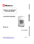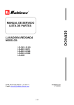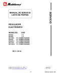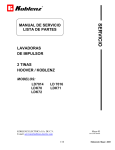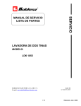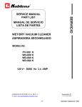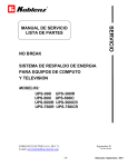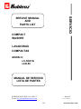
1
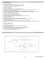
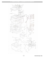
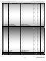
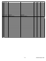
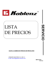
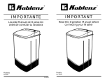
SERVICIO
SERVICE MANUAL
AND
PARTS LIST
COMPACT
WASHER
LAVADORAS
COMPACTAS
MODELS:
LC-5025 B
LCK-50
MANUAL DE SERVICIO
LISTA DE PARTES
KOBLENZ ELECTRICA S.A. DE C.V.
E-mail: [email protected]
Mayo-05
LP-LC50-200505
1/10
Elaborado: Mayo / 2005
INDEX
Page
I. TROUBLE SHUTING.
3
II. PARTS REPLACEMENT.
4
III. ELECTRICAL DIAGRAM.
4
IV. WASHER ASSEMBLY.
5
V. PART LIST.
6
2/10
Elaborado: Mayo / 2005
I. TROUBLE SHUTING
1.- MOTOR DO NOT RUN
POSSIBLE CAUSE
Timer in off position
Defective time cord
Defective timer
Loose electrical connection
Defective motor
Defective capacitar
POSSIBLE SOLUTION
Start timer
Replace line cord
Replace timer
Check connection
Replace motor
Replace capacitar
2.- MOTOR RUNS BUT IMPELLER DO NOT MOVE
POSSIBLE CAUSE
Motor pulley loose
Belt loose or broken
Impeller pulley loose
Impeller loose in shaft
POSSIBLE SOLUTION
Tight set screw on pulley
Tight or replace belt
Replace impeller pulley
Tight impeller screw
3.- EXCESSIVE NOISE OR VIBRATION
POSSIBLE CAUSE
Loose screws
Loose impeller
Loose motor pulley
Damaged pulley or belt
POSSIBLE SOLUTION
Tight firmly
Tight impeller screw
Tight set screw on pulley
Replace
4.- WATER LICKS
POSSIBLE CAUSE
Hose broken
Hose clamp loose
Shaft seal damaged
Shaft bearing or shaft
Damaged
POSSIBLE SOLUTION
Replace hose
Reposition and tight
Replace shaft seal
Replace entire shaft
Assembly
3/10
Elaborado: Mayo / 2005
II. PARTS REPLACEMENT
1.- TO REMOVE THE LID (1)
1.1.- Remove the three screws (5).
1.2.- Lift the lid top cover (3), making sure not to stretch the flexible metal tube (27).
1.3.- Remove the lid (1), bending out the tabs of the cover to disengage the hinge.
1.4.- To reassembly follow the same steps in reverse order.
2.- TO REMOVE THE TIMER (6)
2.1.- Remove the two screws (22) of the rear cover 833) and separate the cover.
2.2.- Remove the four electrical connectors 854) and disconnect the cables from the timer (7), the motor (50) and the line cord (25).
2.3.- Remove the timer knob (4) pulling it out of the timer shaft.
2.4.- Remove the three screws (5) that hold the lid top cover (3), and remove the panel with the timer and the flexible tube.
2.5.- Remove the screw (9) and 11ft the timer cover (10) with the metal tube, taking care to slide the electrical cables out of the metal tube.
2.6.- Remove the two screws (8), lift the timer and replace it.
2.7.- To reassemble follow the same steps in reverse order.
3.- TO REMOVE THE SHAFT ANO BEARING ASSEMBLY (26)
3.1.- Remove the Impeller screw (15) with the conical washer (16), and pull the impeller out of the shaft.
3.2.- Follow the steps of points 2.1 and 2.2.
3.3.- Remove the "V" Belt 838).
3.4.- Remove the six screws (59) that hold the base to the cabinet and separate the base.
3.5.- Place the cabinet horizontally over the bench, extract the pin (29) from the impeller pulley and remove the pulley.
3.6.- Turn loose and remove the nut (36).
3.7.- Remove the complete shaft and bearing assembly pulling out from the interior of the tub and replace.
3.8.- To reassemble follow the same steps in reverse order, make sure the gasket (19) is in position between the shaft assembly (26) and the tub
bottom.
4.- TO REMOVE THE MOTOR (50)
4.1.- Follow the steps 2.1, 2.2, 3.4 and 3.5.
4.2.- Remove the nut (43) and washer (44) that holds the ground terminal of the line cord (25).
4.3.- Disassemble the capacitor (50).
4.4.- Turn loose the set screw (40) on the motor pulley (39) and remove the pulley and fan assembly.
4.5.- Remove from the motor the three screws (51-49) and washer (52), with a screwdriver.
4.6.- Remove the motor (50) and disassemble the three motor supports (57).
4.7.- To reassemble follow the same steps in reverse order.
III. ELECTRICAL DIAGRAM / DIAGRAMA ELECTRICO
4/10
Elaborado: Mayo / 2005
IV. WASHER ASSEMBLY / ENSAMBLE DE LA LAVADORA
5/10
Elaborado: Mayo / 2005
V. PARTS LIST / LISTA DE PARTES
#
PART
NUMBER
1
13-2387-2
LID
2
17-4325-1
PANEL INSERT
LCK50
CSA-UL
KOBLENZ
LCK50
HOOVER
LC5025B
TAPA BLANCA
1
1
1
INSERTO PANEL
1
DESCRIPTION
DESCRIPCION
2
17-4016-6
PANEL INSERT
INSERTO PANEL
3
13-2859-0
LID TOP COVER
TAPA CUBIERTA BLANCA
3
13-2421-9
LID TOP COVER
TAPA CUB. C/IMP.
3
13-2366-6
LID TOP COVER
TAPA CUB. IMP.
4
13-2367-4
TIMER KNOB
PERILLA TIMER LOCK50
4
13-2343-5
TIMER KNOB
PERILLA
5
01-1896-8
SCREW No. 7-16 x 3/8
6
13-2616-4
7
7
1
1
1
1
1
1
TORNILLO TRUSS “A” 7-16 X 3/8
9
3
3
TIMER COVER LID
BASE CUBIERTA TIMER
1
38-0398-8
TIMER
RELOJ
1
38-0312-9
TIMER
RELOJ
1
1
8
01-1895-0
SCREW No. 10-16 x 1/2
PIJA TRUSS 10-16 UNC X 11.4 MM
2
2
2
9
01-0267-3
SCREW No. 4-24 x 1/2
PIJA TRUSS 4-24 UNC X 11.4 MM
1
10
13-2617-2
TIMER COVER
TAPA TIMER
1
11
13-2860-8
TOP COVER
SOPORTE CUB.
1
1
11
13-2388-0
TOP COVER
SOPORTE CUB.
12
12-0749-7
SEAL
SELLO BOSTIK 3030-10
13
17-4250-1
LEVEL ESPECIFICATIONS
ETIQUETA ESPECIFICACIONES
1
14
17-4322-8
WATER LEVEL LABEL
ETIQUETA NIVEL DE AGUA
1
14
13-3875-6
WATER LEVEL LABEL
ETIQUETA NIVEL DE AGUA
1
1
15
01-1917-2
SCREW No. 12-24 x 1 INOX
TORNILLO No. 12-24 x 1 INOXIDABLE
1
1
1
16
04-0580-3
CONICAL LOCK WASHER
ROLDANA CONICA ESTRIADA
1
1
1
17
13-2668-5
IMPELLER
IMPULSOR
1
17
13-2386-4
IMPELLER
IMPULSOR
1
1
18
04-0529-0
IMPELLER WASHER
ROLDANA IMPULSOR
1
1
1
19
12-0748-9
SEAL
SELLO AGUA GABINETE TINA
1
1
1
1
1
0.3 M
1
1
0.3 M
0.3 M
20
17-3971-3
KOBLENZ INSERT
MEDALLON KOBLENZ
20
17-3940-8
MILENIUM INSERT
EMBLEMA MILENIUM
21
12-0750-5
GASKET
SELLO GABINETE CUBIERTA
2
2
2
22
01-1893-5
SCREW No. 8-18 x 1/2
TORNILLO No. 8-18 x 1/2
3
3
3
1
1
1
1
1
23
13-2222-1
HOSE BRAKET
GANCHO DE MANGUERA
1
24
13-1540-7
CAPACITOR PLASTIC STRAP
CINTURON DE PLASTICO DE CAPACITOR
1
25
28-1279-0
LINE CORD
CORDON DE LINEA
1
25
09-1183-4
LINE CORD
CORDON DE LINEA
26
46-2473-0
SHAFT AND BEARING ASSEMBLY
ENSAMBLE DE CHUMACERA
1
1
1
26a
04-0586-0
LOCK WASHER
RONDANA CANDADO
1
1
1
26b
12-0747-1
SEAL
SELLO DE CUERPO DE CHUMACERA
1
1
1
26c
04-0240-4
LOCK WASHER TYPE C
RONDANA CANDADO
2
2
2
26d
04-0545-6
FLAT WASHER
ROLDANA INOXIDABLE DIAMETRO 12.82 mm
2
2
2
26e
26-0209-2
TOP BEARING
CHUMACERA SUPERIOR
1
1
1
26f
13-2039-9
BEARING BODY
CUERPO DE CHUMACERA
1
1
1
26g
25-1227-5
SHAFT
FLECHA IMPULSOR MILENIUM
1
1
1
26h
37-0228-9
FELT BUSHING
ROLDANA FIELTRO IMPULSOR MILENIUM
1
1
1
1
1
1
26i
26-0210-0
BOTOM BEARING
CHUMACERA INFERIOR
27
26-0233-2
METAL TUBE FLEXIBLE
TUBO FLEXIBLE METALICO
28
13-2607-3
PLASTIC STRAP
CINTURON AMARRE DE CABLES
2
1
1
29
25-0415-7
SPIROL PIN
PERNO ESPIROL 5/32 x 1”
1
1
1
30
13-2861-6
CABINET
GABINETE
1
30
13-2385-6
CABINET
GABINETE
1
1
6/10
0.74 M
Elaborado: Mayo / 2005
#
PART
NUMBER
DESCRIPTION
DESCRIPCION
LCK50
CSA-UL
KOBLENZ
LCK50
HOOVER
LC5025B
31
13-2221-3
HOSE HANGER
SOPORTE DE MANGUERA
1
1
1
32
12-0732-3
DRAIN HOSE
MANGUERA DE DSAGÜE
1
1
1
33
13-2665-1
REAR COVER
TAPA POSTERIOR
1
33
13-2364-1
REAR COVER
TAPA POSTERIOR AZUL
1
33
13-2365-8
REAR COVER
TAPA POSTERIOR
34
27-0268-6
NOSE CLAMP
ABRAZADERA DE 34.85 mm DIAMETRO
1
1
35
05-4377-7
BAFFLE
BAFLE METALICO
1
36
13-2111-6
SHAFT BEARING NUT
TUERCA CHUMACERA
1
37
13-2038-1
IMPELLER PULLEY
POLEA DE IMPULSOR DE PLASTICO
1
1
1
38
12-0735-6
“v” BELT
BANDA “v” MOTOR REVERSIBLE
1
1
1
39
06-0877-8
MOTOR PULLEY
POLEA DE MOTOR
1
1
1
40
01-0883-7
SET SREW
TORNILLO
1
1
1
41
13-1753-6
MOTOR FAN
VENTILADOR
1
1
1
42
01-0537-9
SCREW No. 6-20 x 7/8
TORNILLO No. 6-20 x 7/8
3
3
3
43
02-0007-1
HEXAGONAL NUT 8-32
TUERCA HEXAGONAL 8-32
2
44
04-0276-8
WAHER No. 8
ROLDANA No. 8
2
1
1
1
1
1
45
13-2671-9
CABINET BASE
BASE DE GABINETE
45
13-2390-6
CABINET BASE
BASE DE GABINETE AZUL
45
13-2389-8
CABINET BASE
BASE DE GABINETE
46
12-0763-8
HEYCO STRAIN RELIEF
PROTECTOR CORDON
1
1
1
47
28-1297-2
CAPACITOR WIRE ASSEMBLY YELLOW
ENSAMBLE CABLE AMARILLO DE CAPACITOR
1
1
1
1
1
48
28-1296-4
CAPACITOR WIRE ASSEMBLY BLACK
ENSAMBLE CABLE NEGRO DE CAPACITOR
1
1
1
49
01-1918-0
SREW TYPE No. 12 x 1/4
TORNILLO TIPO A No. 12 x 1/4
2
2
2
50
44-0347-3
REVERSIBLE MOTOR & CAPACITOR 40μF
MOTOR REVERSIBLE
1
1
1
51
01-0312-7
SCREW TYPE A No. 14 x 1/4
TORNILLO TIPO A 14 x 1/4
1
3
3
4
4
3
3
6
6
52
04-0578-7
WASHER
ROLDANA
3
53
01-2041-0
GROUND SCREW
TORNILLO DE TIERRA
1
54
10-0148-6
ELECTRIC CONECTOR
CONECTOR ELECTRICO
4
55
13-2693-3
TIMER COVER ELBOW
CODO DE CUBIERTA DE TIMER
1
2
56
01-0318-4
SCREW TYPE AB 6 x 14
TORNILLO TIPO AB 6 x 14
57
12-0752-1
MOTOR SUPPORT
SOPORTE DE MOTOR
3
58
17-4320-2
LEVEL ID
NIVEL DE TAPA
1
59
01-1916-4
SCREW No. 10-12 x 3/4
TORNILLO No. 10-12 x 3/4
6
60
17-4323-6
LEVEL ELECTRIC GROUNDING
NIVEL ELECTRICO DE TIERRA
1
7/10
Elaborado: Mayo / 2005
INDICE
Pág.
I. FALLAS Y CORRECCIONES.
9
II. INSTRUCCIONES PARA CAMBIO DE PARTES.
9
III. DIAGRAMA DE CONEXION PARA LA LAVADORA.
4
IV. ENSAMBLE LAVADORA.
5
V. LISTA DE PARTES.
6
8/10
Elaborado: Mayo / 2005
I. FALLAS Y CORRECCIONES
1.- MOTOR NO TRABAJA
CAUSAS
Fusible Clavija o cable defectuosos
Timer defectuoso
Timer en posición de apagado
Bobinas del motor abiertas o en corto
Capacitor defectuoso
CORRECCIONES
Cambiar partes en mal estado
Cambiar Timer
Colocarlo en la posición correcta
Reemplazar el motor
Reemplazar capacitor
2.- EL MOTOR TRABAJA PERO EL IMPULSOR NO SE MUEVE
CAUSAS
CORRECCIONES
Polea del motor floja o dañada
Banda floja o rota
Polea impulsor floja o barrida
Apretar ó reemplazar
Ajustar banda o reemplazar
Apretar polea ó reemplazar
3.- VIBRACIONES EXCESIVAS – FUNCIONAMIENTO RUIDOSO
CAUSAS
CORRECCIONES
Sujeciones flojas
Polea impulsor floja
Banda floja
Apretar correctamente
Apretar correctamente
Apretar correctamente
4.- FUGA DE AGUA
CAUSAS
CORRECCIONES
Manguera rota
Abrazadera mal colocada
Sello de agua dañado
Chumaceras dañadas
Reemplazar manguera
Colocar correctamente
Reemplazar sello
Reemplazar chumaceras
SPECIFICATIONS / ESPECIFICACIONES
VOLTAGE / VOLTAJE
127 V ~
Hz
CAPACITY / CAPACIDAD
60 Hz
5 Kgs.
II. INSTRUCCIONES PARA CAMBIO DE PARTES
1.- DESENSAMBLE DE LA TAPA (1)
1.1.- Quite las tres pijas (5).
1.2.- Levante la tapa para soporte cubierta (3) la cuál viene ensamblada con la tapa (1) y el timer (6).
1.3.- Desensamble la tapa y reemplace invirtiendo la secuencia de desensamble.
2.- DESENSAMBLE DEL TIMER (6)
2.1.- Siga los pasos indicados en los puntos 1-1 y 1-2.
2.2.- Quite la perilla (4) así cómo los dos tornillos (8).
2.3.- Quite las tres pijas (22) que sujetan la tapa posterior (33) al gabinete (30).
2.4.- Desconecte las terminales del timer (6).
2.5.- Reemplace el timer, invirtiendo la secuencia de desensamble.
3.- DESENSAMBLE DEL CONJUNTO CHUMACERA (26)
3.1.- Quite el tornillo de impulsor (15) y la rondana conica (16).
3.2.- Quite el impulsor (17) así cómo la roldana especial de impulsor (18).
3.3.- Quite las seis pijas (59) y desensamble el gabinete (30) con la base (45).
3.4.- Desmonte la banda (38), desconecte el timer (6) y separe el gabinete (30) de la base (45).
3.5.- Coloque en forma horizontal el gabinete (30) con un punzón de 1/4” bote el perno espirol (40).
3.6.- Quite la polea impulsor (39) y desatornille y quite la tuerca de chumacera (36).
3.7.- Por la parte interior del gabinete (30) saque el conjunto chumacera que viene ensamblado con los componentes 9a, 9b, 9c, 9d, 9e,
9f, 9g, 9h, 9i.
3.8.- Reemplace el nuevo conjunto chumacera invirtiendo la secuencia del desensamble.
NOTA: Cuando conecte las terminales, siga la secuencia con sus respectivos colores.
4.- DESENSAMBLE DEL MOTOR (50)
5.1.- Siga los pasos indicados en los puntos 3-3 y 3-4.
5.2.- Desconecte las terminales del cable de línea (25) así cómo del capacitor (45).
5.3.- Quite los tres tornillos (49) con las roldanas (44) que sujetan el motor con la base (45).
5.4.- Reemplace el motor invirtiendo la secuencia de desensamble, colocando los amortiguadores del motor (57) como estaba
inicialmente.
NOTA: Cuando reemplace el nuevo motor ajuste la banda con la tensión adecuada.
9/10
Elaborado: Mayo / 2005
SERVICIO
CUANDO ORDENE,
NO OLVIDE ESPECIFICAR:
• NUMERO DE PARTE
• DESCRIPCIÓN
NÚMERO DE MODELO
NOTA:
LOS NUMEROS DE LOS DIBUJOS SON
SOLO PARA PROPOSITOS DE IDENTIFICACION
TALLERES DE SERVICIO DIRECTOS DE FABRICA
DIVISION DEL NORTE
OFICINA CENTRAL
Av. División del norte No. 416
Col. Del Valle
C.P. 03100 México, D.F.
Tel. 5543-3535
Río San Joaquín No. 345
Col. Ampliación Popo
C.P. 11480 México, D.F.
Tel: 5250-91-35
LAVADORAS D.F.
Y ZONA METROPOLITANA
Servicio a Domicilio
Tels.: 5864-03 85 / 5864-03-8
VALLEJO
Norte 45 No. 802, Col. Ind. Vallejo
C.P. 02300, México D.F.
Tels.: 5567-80-45 35-81
CUAUTITLAN
Av. Ciencla No. 28 Cuautillán Izcalli
Edo. de México, C.P. 54730
Tels.: 5864-08-85 / 5864-03-86
Del lnterior de la República lIamar al 01 (800)84-94-711
FABRICA
GUADALAJARA JAL.
Cincinatti 125 Sector Reforma
C.P. 44440 Guadalajara, Jal.
Tels: 01 (33) 3610-05-71
MONTERREY N.L.
KOBLENZ ELECTRICA, SA DE C.V.
Av. Ciencia No. 28 Cuautitlán Izcalli
Edo. de México, C.P. 54730. Tel.: 5864-03-00
KOBLENZ ELECTRICA S.A. DE C.V.
E-mail: [email protected]
Platón Sánchez 1860 norte
Col. Primero de Mayo
C.P. 64580 Monterrey, N.L.
Tels: 01 (81) 8375-14-81
Mayo-05
LP-LC50-200505
10/10
Elaborado: Mayo / 2005