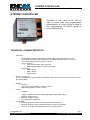
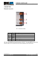
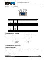
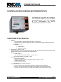
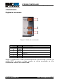
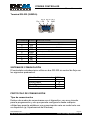
1
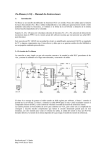
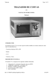
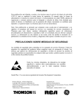
Model VST11I Version 2.0 © 2008 DCM Sistemes, S.L .All right reserved. Specifications are subject to change without notice. USER M ANUAL STROBE CONTROLLER This Page Intentionally Left Blank This Page Intentionally Left Blank STROBE CONTROLLER User manual INDEX English……………………………………………………………..5 Español…………………………………………………………...13 DCM Sistemes S.L. http://www.dcmsistemes.com Page 3 e-mail: [email protected] This Page Intentionally Left Blank This Page Intentionally Left Blank STROBE CONTROLLER User manual STROBE CONTROLLER Controller of one output of 6A, with an input of pulse wide and programmable pulse between 0 µs and 10 ms in steps of 4µs. Programming via RS-232 stored in non-volatile memory. TECHNICAL CHARACTERISTICS. • Assembly: o o o All STROBE modules are aligned in rows by simply snap locking them onto the symmetrical mounting rail in accordance with EN 50 022 (DIN 46277/3). They are removed by pulling back the orange snap lock. Type of housing: Polycarbonate PC-F fiber reinforced Inflammability class V0 (UL94) color: black Dimensions: Width: 90mm. Deep: 103mm. Height: 75mm. • Power: +24Vdc. 1A. The system disposes of large capacity condensers, which are able to store enough power to give the output pulses. • Outputs: o Quantity: 1 o Type: open drain MOSFET, +24Vdc common. o Maximum intensity by output: 6 Amp. Inputs: o Quantity: 1 o o Trigger: negative or positive edge trigger equal or great than +5Vdc. o Minimun voltage: 0Vdc. o Maximun voltage: +24Vdc. o Input impedance: 60KOhms. Led indicator: o Power: A green led comes on when the power is switched on. o Running: A blinking red led indicates when the system is operative. o RS-232: A red led is activated when there is communication. • • DCM Sistemes S.L. http://www.dcmsistemes.com Page 5 e-mail: [email protected] STROBE CONTROLLER User manual CONNECTION External connector Pic 1. Connection detail. Terminal Signal Description 1 +24Vdc Power Input voltage 2 GND 0v input power 3 OUT+ Output 1, Positive terminal. 4 OUT- Output 1, Negative terminal 5 Disp 1 Output 1 trigger input. 6 GND GND for trigger input NB: The outputs OUT+ permanently produce +24VDC. The output OUT- are put on the ground charge, when activated and left at high impedance when deactivated. DCM Sistemes S.L. http://www.dcmsistemes.com Page 6 e-mail: [email protected] STROBE CONTROLLER User manual RS-232 terminal (SUBD-9). Pin 2 Pin 3 Pin 5 Pin 1 RX TX GND Pin 6 Pin 9 Pin number SIGNAL DESCRIPTION 1 NC Not connected 2 RX Data input 3 TX Data output 4 NC Not connected 5 GND Ground of RS-232 6 NC Not connected 7 NC Not connected 8 NC Not connected 9 NC Not connected COMMUNICATION SYSTEM The stroboscopic controller uses a non-flow control RS-232 with the following parameters. Communication speed 9600 bps Start bit Dates bits Parity bit Stop bit 1 8 No 1 COMMUNICATION PROTOCOL Communication type There are two methods of communication with the device: the first is more convenient to program and the other allows usage from whichever software that is able to establish a serial communication in text mode. - Program mode. HyperTerminal mode. DCM Sistemes S.L. http://www.dcmsistemes.com Page 7 e-mail: [email protected] STROBE CONTROLLER User manual HIPERTERMINAL mode The first steep is to choose the correct mode. In order to do this a string “mode” is sent. If sent a second time it will be switched to program mode. The following will appear on the screen: STROBE CONTROLLER. (c) DCM Sistemes 2008 Model VST11I -- SW v2.00 AVAILABLE COMMANDS v.- Show selected pulse width u.- To increase pulse width d.- To decrease pulse width p.- Set new pulse width t.- Set delay time e.- Show delay time c.- Set trigger edge f.- Show trigger edge ?.- Command menu Show the command menu and it is ready for use. Command v – Show the weight pulse The following will appear: Pulse width = (X * 4)uS. X is therefore the value between 0 and 2500 of the output. Command u – To increase pulse width Up the pulse weight in steps of one unit. The following will appear:: New pulse width = (X * 4)uS. X is therefore the value between 0 and 2500 of the output. Command d – To decrease pulse width Down the pulse weight in steps of one unit. The following will appear: DCM Sistemes S.L. http://www.dcmsistemes.com Page 8 e-mail: [email protected] STROBE CONTROLLER User manual New pulse width = (X * 4)uS. X is therefore the value between 0 and 2500 of the output. Command p – Set the weight pulse The following will appear: New value [0..2500]= The new value should then be introduced followed by ENTER Command t – Set the delay time Used to change the initial time of delay in steps of 410useg. With a range between 0-27 seconds. The following will appear: New value [0..65535]= The new value should then be introduced followed by ENTER Command e – Show delay time Show the value of delay time. The following will appear: Delay time = (x * 410)uSeg. X is therefore the value between 0 and 65535 . Command c – Set trigger edge Allows the trigger edge to be changed when there is a rise or fall in power level. The following will appear: Set trigger edge (rise/fall) (a/b)?= You have to introduce a for a rise in the input trigger and b for the trigger to activate when the input fall. DCM Sistemes S.L. http://www.dcmsistemes.com Page 9 e-mail: [email protected] STROBE CONTROLLER User manual Command f – Show trigger edge Show the status of the edge in the selected output. The following will appear: Rise edge (1) if it is of ascent or, Fall edge (0) if it is of descent. Command ? – Show the command menu Command mode – Switch between text mode and abbreviated mode. DCM Sistemes S.L. http://www.dcmsistemes.com Page 10 e-mail: [email protected] STROBE CONTROLLER User manual Abbreviated mode In order to program PLC’s and other devices. It is used in the same way as the HyperTerminal mode, with the same commands but without the strings requesting or replying the value. For example: If the u command is introduced the system will respond with an x, with x being the value of the width pulse of the device. DCM Sistemes S.L. http://www.dcmsistemes.com Page 11 e-mail: [email protected] This Page Intentionally Left Blank This Page Intentionally Left Blank STROBE CONTROLLER Manual de usuario CONTROLADOR DE DISPARO ESTROBOSCÓPICO Controlador de una salida de 6 amperios, con entrada de disparo y ancho de pulso programable entre 0 µs y 10ms en pasos de 4µs. Programación vía RS-232 almacenada en memoria no volátil. CARACTERÍSTICAS TÉCNICAS • • • • • Formato: o Caja Carril DIN en policarbonato reforzado con fibra PC-F. o Montaje mediante simple engatillado sobre los perfiles de soporte simétricos según EN 50 022 (DIN 46277/3). o Medidas: Ancho: 90mm. Alto: 75mm. Profundo: 103mm. Alimentación: +24Vdc. 1Amp. El sistema dispone de unos condensadores de gran valor, que acumulan la carga necesaria para proporcionar los pulsos de corriente durante los disparos. Salidas: o Nº de salidas: 1 o Tipo: MOSFET a drenador abierto. +24Vdc común. o Intensidad máxima por salida: 6 Amp. Entradas: o Número de entradas: 1. o Disparo: por flanco positivo o negativo superior o igual a +5Vdc. o Tensión mínima: 0Vdc. o Tensión máxima: +24Vdc. o Impedancia de entrada: 60KOhms. Indicadores a led: o Power: Led verde que se enciende cuando el sistema recibe alimentación. o Runing: Led rojo intermitente que indica que el sistema está en funcionamiento. o RS-232: Led rojo que se activa cuando el controlador recibe algún dato vía serie. DCM Sistemes S.L. http://www.dcmsistemes.com Page 13 e-mail: [email protected] STROBE CONTROLLER Manual de usuario CONEXIONADO Regleta de conexiones. Figura 1. Detalle de conexionado. Nº Terminal SEÑAL DESCRIPCIÓN 1 +24Vdc Entrada positiva de alimentación. 2 GND Masa de la entrada de alimentación. 3 OUT+ Salida 1, terminal positivo. 4 OUT- Salida 1, terminal negativo. (Drenador del transistor 5 6 Disp 1 GND MOSFET) Entrada de disparo de la salida 1. Masa de la entrada de disparo. Nota: La salida OUT+ están permanentemente suministrando +24Vdc. La salida OUT- se pone a masa cuando se activa, quedando en alta impedancia cuando está desactivada. DCM Sistemes S.L. http://www.dcmsistemes.com Page 14 e-mail: [email protected] STROBE CONTROLLER Manual de usuario Terminal RS-232 (SUBD-9). Pin 2 Pin 3 Pin 5 Pin 1 RX TX GND Pin 6 Pin 9 Nº Terminal SEÑAL DESCRIPCIÓN 1 NC No conectado 2 RX Terminal de entrada de datos RS-232 3 TX Terminal de salida de datos RS-232 4 NC No conectado 5 GND Masa del puerto RS-232 6 NC No conectado 7 NC No conectado 8 NC No conectado 9 NC No conectado SISTEMA DE COMUNICACIÓN El controlador estroboscópico utiliza un bus RS-232 sin control de flujo con los siguientes parámetros. Velocidad de comunicación 9600 bps Bits de Start 1 Bits de Datos 8 Bit de Paridad No Bits de Stop 1 PROTOCOLO DE COMUNICACIÓN Tipo de comunicación Existen dos modos de comunicarse con el dispositivo, uno muy cómodo para la programación y otro que permite configurarlo desde cualquier utilidad que permita establecer una comunicación serie en modo texto con un dispositivo (ej. Hiperterminal de Windows). DCM Sistemes S.L. http://www.dcmsistemes.com Page 15 e-mail: [email protected] STROBE CONTROLLER Manual de usuario - Modo programación. - Modo HyperTerminal. Modo HYPERTERMINAL Lo primero que hay que hacer es decirle al dispositivo que tiene que funcionar en este modo para ello se le enviará la cadena mode. Si se vuelve a enviar esta cadena conmutará al modo programación. Entonces aparecerá el siguiente menú: STROBE CONTROLLER. (c) DCM Sistemes 2008 Model VST11I -- SW v2.00 AVAILABLE COMMANDS v.- Show selected pulse width u.- To increase pulse width d.- To decrease pulse width p.- Set new pulse width t.- Set delay time e.- Show delay time c.- Set trigger edge f.- Show trigger edge ?.- Command menu Muestra los comandos y ya se puede manejar el dispositivo. Comando v – Ver ancho de pulso de la salida Aparecerá: Pulse width = (X * 4)uS. Siendo x el valor entre 0 y 2500 que tiene la salida. Comando u – Aumentar Ancho de Pulso Aumenta el ancho de pulso en incrementos de una unidad. Aparecerá: New pulse width = (X * 4)uS. Siendo x el valor entre 0 y 2500 que tiene la salida. DCM Sistemes S.L. http://www.dcmsistemes.com Page 16 e-mail: [email protected] STROBE CONTROLLER Manual de usuario Comando d – Disminuir Ancho de Pulso Disminuye el ancho de pulso en decrementos de una unidad. Aparecerá: New pulse width = (X * 4)uS. Siendo x el valor entre 0 y 2500 que tiene la salida. Comando p – Poner nuevo Ancho de Pulso Aparecerá: New value [0..2500]= Se debe introducir un valor y a continuación INTRO Comando t – Configurar Tiempo de Espera inicial Vale para poner un tiempo de espera antes del disparo con pasos de 410useg. El rango está entre 0 y 27 segundos. Aparecerá: Nuevo valor [0..65535]= Se debe introducir un valor y a continuación INTRO Comando e – Ver Tiempo de Espera inicial Muestra el valor de tiempo de espera inicial. Aparecerá: Delay time = (x * 410)uSeg. Siendo x el valor entre 0 y 65535 . Comando c – Configurar el flanco de disparo DCM Sistemes S.L. http://www.dcmsistemes.com Page 17 e-mail: [email protected] STROBE CONTROLLER Manual de usuario Permite modificar el valor del flanco de disparo, pudiendo ser de subida o de bajada. Aparecerá: Set trigger edge (rise/fall) (a/b)?= Se debe introducir a para que el flanco sea de subida y b para un flanco de bajada. A continuación se debe pulsar INTRO Comando f – Ver flanco de disparo Vale para comprobar el valor del flanco en el dispositivo seleccionado: Aparecerá: Rise edge (1) si es de subida o, Fall edge (0) si es de bajada. Comando? – Muestra el menú de comandos Comando mode – Conmuta del modo texto a modo corto. DCM Sistemes S.L. http://www.dcmsistemes.com Page 18 e-mail: [email protected] STROBE CONTROLLER Manual de usuario Modo CORTO Sirve para facilitar la programación en autómatas u otros dispositivos. Se usa exactamente igual que el modo HyperTerminal, con los mismos comandos, pero no aparecen cadenas de texto preguntando el dato o devolviendo información. Ejemplo: Si se introduce el comando u el sistema hará un eco con x, siendo x el valor del ancho de pulso del dispositivo. DCM Sistemes S.L. http://www.dcmsistemes.com Page 19 e-mail: [email protected]