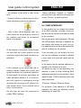
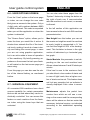
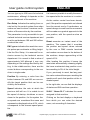
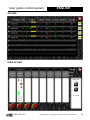
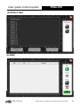
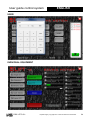
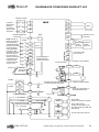
1
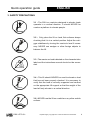
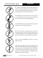
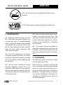
Show Lift 4/55
GB ELECTRIC LIFT
OPERATING INSTRUCTIONS
E
ELEVADOR ELÉCTRICO
MANUAL DE INSTRUCCIONES
V 01.13
ELECTRIC LIFTING TOWER
Show Lift 4/55
TORRE ELEVADORA ELÉCTRICA
Show Lift 4/55
CERTIFICATIONS / CERTIFICACIONES
BGV-C1
BGG-912
EC Conformity Declaration pursuant to the EC Machinery
Directives 89/392/CE and 98/37/CE: Manual lifters
MADE IN SPAIN (EU)
Manufacturer - Fabricante
PRO LIFTS S.L.
Pol. Inglés, Nave 6
46181 Benisanó (Valencia)
+34 96 171 81 86
[email protected] - www.prolifts.es
Este manual de usuario y catálogo anexo de piezas de repuesto es propiedad de PRO LIFTS S.L.
Queda prohibida su reproducción total o parcial por cualquier medio de la tecnología actual permita.
Deposito legal y copyright 2012. Todos los derechos reservados.
Quick operation guide
GENERAL CONTENTS:
ENGLISH
The model type, production year and serial number must be quoted in any queries
or orders for spare parts.
1. - INTRODUCTION
2. - TECHNICAL INFORMATION
2. TECHNICAL INFORMATION
3. - SAFETY PRECAUTIONS
4. - MAINTENANCE
2.1 - Towerlift Showlift.
5. - GUARANTEE
6. - USER GUIDE BASE ASSEMBLY
2.2 - Designed to lift loads vertically to various heights to support lighting and sound
7. - INNER ELECTRONICS AND
systems.
INSTALATION GUIDE
8. - USER GUIDE CONTROL SYSTEM
2.3 - Maximum load : 55 Kg (121 lb).
9. - SCREENSHOTS FROM CONTROL
2.4 - Minimum load : 10 Kg (22 lb).
SYSTEM
2.5 - Maximum height : 4.11 m (13.48’).
2.6 - Minimum height : 1.27 m (4.17’).
1. INTRODUCTION
2.7 - Area of base : 87x86 cm
Dear customer, In order to ensure a safe
and reliable operation of the Slift 4/55
towerlift please follow the instructions in
this booklet carefully. Before operating the
lift, read the instructions completely and
please note the technical information contained within this manual.
2.8 - Unit weight :88 Kg (194,01 lb).
2.9 - Base weight: 18 Kg (39,68 lb).
2.10 - Construction material : Main body in
extruded aluminium 6082-T6 profile. Base
and legs are made of steel profile according to DIN2394. Catches and safety rack
of ST-37 steel.
All VMB products undergo very rigorous
testing, under strict conditions and they
are monitored continuously during the
manufacturing process. In order to guarantee the lifts function and safety, only
original parts from the manufacturer must
be used. If any parts other than those of
the manufacturer are used, or the product
is modified in any way, the user forfeits all
warranty rights to claim.
2.11 - Cable : Steel DIN 3060. Quality 180
Kg/mm2 twist resistant.
Cable diameter: 4 mm.
2.12 - Adjustable stabilizing platforms with
ruber non-slip supports.
2.13 - Base and supports are finished in
textured polyester. The tower is supplied
with black finish.
2.14 - Wheels to transport the lift when
folded.
VMB reserves the right to modify the product specifications without prior notice.
PRO LIFTS S.L.
Depósito legal y copyright 2011. Todos los derechos reservados.
3
Quick operation guide
ENGLISH
3. SAFETY PRECAUTIONS.
3.1 - The Slift is a machine designed to elevate loads
upwards in a vertical direction, It should NEVER be
used as a platform to elevate people.
3.2 - Only place the lift on hard, flat surfaces always
checking that it is in a vertical position. Adjust the outrigger stabilisers by turning the cranks to level if necessary. NEVER use wedges or other foreign objects to
balance the lift.
3.3 - The maximum load indicated on the characteristics
label and the instructions manual should not be exceeded.
3.4 - This lift should NEVER be used to elevate a load
that has not been properly checked. It is necessary to
verify that the load is correctly supported and centred
on the appropriate lift support so that the weight of the
load will only elevate in a vertical direction.
3.6 - NEVER use the lift on a vehicle or any other mobile
surface.
PRO LIFTS S.L.
Depósito legal y copyright 2011. Todos los derechos reservados.
4
Quick operation guide
ENGLISH
3.7 - If there is a possibility of strong winds or gusts, place the lift on the ground firmly and secure the base with
the use of straps. NEVER attach a strap to a vehicle or
any other object that can possibly be moved.
3.8 - NEVER move the lift whilst if it is carrying a load.
It is not advisable to carry out any type of horizontal
movement even small positional adjustments.
3.9 - NEVER allow any team member below the load or
anybody else in the lifts operating zone.
3.10 - Take care with all obstacles above the lift and
its extension zone such as cornices, balconies, and
luminous signboards. It is very important to avoid the
presence of all types of cables below the extended lift.
3.11 - Do not use stepladders on the lift or use it as a
support for them.
3.12 - Before using the lift, check the condition of the
cable. The cable should not contain broken threads or
show any signs of crushed/flattened areas. NEVER use
faulty cables, always change them if there is any doubt. Only use steel cables reference: DIN 3060. Quality:
180KG/mm and torsion resistant.
PRO LIFTS S.L.
Depósito legal y copyright 2011. Todos los derechos reservados.
5
Quick operation guide
ENGLISH
3.13 - All sections must be lowered first, before transportation.
3.17 - Only original replacement parts should be used.
O R I GI N A L
4. MAINTENANCE.
4.1 - Regularly check the state of the cable. If the cable has broken threads, or if
it shows any signs of crushed/flattened
areas, it should be changed and replaced
immediately with a new one. Do not use
the lift if the cables are in bad condition.
Only use steel cables reference: DIN
3060 torsion resistant.
4.2 - The lift is supplied from the factory
completely greased. However, it is recommended to periodically grease according
to use, the gearing, the axis bearings and
the sections.
4.3 - All lifts should undergo an annual
technical inspection carried out by an
authorized VMB dealer to check the certifications and general condition of all the
lift’s elements and security systems involved in the lift’s use.
PRO LIFTS S.L.
4.4 - Only use original spare parts to guarantee a continued security level. The
user loses all rights to warranty if any spare parts other than originals are used or
carries out any modification or alteration
to the towerlift.
4.5 - To request a spare part please indicate the corresponding code which can
be found in this manual together with the
lift’s serial number and year of manufacture.
5. GUARANTEE.
The warranty period for this lift is 2 years
from the date of purchase.
PRO LIFTS S.L. promises, that from the
date of purchase and during the warranty
period to resolve any faults that may occur, produced through defect material or
fabrication. Damage caused by improper
use, product modification, third party manipulation or accidental fire are not covered by this warranty.
Depósito legal y copyright 2011. Todos los derechos reservados.
6
User guide base assembly
ENGLISH
Show Lift 4/55
6.- USER GUIDE BASE ASSEMBLY.
6.1 - Place the base front piece (S001) and the base
back piece (S002) on a firm, flat surface with an approximate distance between them of 35 cm, set the levelling
platforms (S227) to their minimum height to achieve a
horizontal surface .
6.2 - Tilt the tower and place it behind the base back
piece (S002) using their transport wheels, upload and
slide the tower onto the base, and match the holes of the
support of the tower with the holes at the bases.
6.3 - Once the tower is properly placed above the base,
fix it by screwing the wing nuts (6404).
6.4 - Level the tower by using the crank knobs of the
levelling platforms (S227) at the base. Please use a proffesional level.
6.5 - How to place the load:
Place the load on the top plate (S022), center and fix the
load firmly to the holes intended for this purpose (The
maximum load is 55 kg (121 lb), the elevator should NEVER be overloaded (over 55 kg). Safety at work is the
most important element.
PRO LIFTS S.L.
Depósito legal y copyright 2011. Todos los derechos reservados.
7
Inner electronic and instalation guide
7 - INNER ELECTRONIC AND
INSTALATION GUIDE.
On the one hand, the connection for machine operation and on the other, completely independent, the power connection to
the computer/s which should be connected
in the top head.
Index:
7.1
7.2
7.3
7.4
- Installing the SLift
- GateWay: Node Configuration
- Variable speed
- Wiring
7.1.1 - Power Connections:
Each S.lift machine has interated electronics which enable you to communicate
with the control system, control the inverter
and view both actions and possible machine errors.
The inverter allows full control of the engine, requiring a previous “tuning”, which
will manage the tower. This allows you to
send engine information to the inverter in
order to manage the properties of the engine, and adapt the work of the machine
depending on its response.
The general configuration of the inverter
comes preset from factory, so it is recommended not to change any parameters
from the panel of the equipment.
In the same way, the gateway or interface
of communication with the control system
is factory set and addressed, so it is not
advisable to touch the parameters set in it,
so as to ensure a proper operation.
7.1 - INSTALLING THE SLIFT
After placing the machines at the appropriate site, proceed to wire the power lines
and power distribution. Each S.Lift has separate power connections.
PRO LIFTS S.L.
ENGLISH
All power connections use PowerCon connectors. The power connection for the machine, has a second grey PowerCon connector, so it is possible to power a second
machine, using the appropriate cable from
another machine installed near by.
You should not power more than 4 S.Lift
machines from the same power line. The
control system has a small power distributor, where several lines can be shared to
power the equipment installed. Power for
the top head computer/s can be taken from
stage distributors prepared for this purpose.
Do not use the distributor of the control
system to power the top head equipment,
since it has limited power and could the
protections prepared exclusively for powering the machines to fail.
7.1.2 - Communication Connections:
Use the 3-pin XLR connectors located
on the connection panel, section “Machine”, so that the machines and the control
system can communicate together. Do
not confuse this with the DMX information
which is explained later and is differentiated in another section of the patch panel.
Depósito legal y copyright 2011. Todos los derechos reservados.
8
Inner electronic and instalation guide
For this purpose you should use a DMX
120 ohm cable or similar, and always using
3-pin XLR connectors.
The ‘pinout’ is shown below:
XLR Pin 1: Ground (ground)
XLR pin 2: Data –
XLR pin 3: Data +
The ‘pinout’ of a standard DMX cable has
been respected to make these connections compatible with DMX wiring using
this type of connector.
You need to close the bus communication
of the machine with a 120 Ohm terminator
at the free end of the last installed machine. Since it is a different protocol to the
DMX, it has higher speed, bidirectional
data capacity, so the use of this closure or
terminator is OBLIGATORY.
For the DMX, 5-pin XLR connectors have
been prepared as protocol standard, to differentiate bus connections of the machine
from the control lighting or other equipment mounted on the top head.
ENGLISH
7.2 - GATEWAY:
Node Configuration:
‘Gateway’ refers to the interface that is installed on each S.Lift machine that allows
communication of each one with the control system and install on to it, in a modular form, elements that interact with the
machine, so as to give orders and receive
information delivered by each S.Lift machine.
‘Node’ refers to every machine installed
with its assigned and unique address, not
repeated, differentiated from the others.
In contrast to DMX, we must number the
nodes sequentially. This is necessary to
make the control system recognize every
machine installed; always start from node
2 (the first S.Lift machine) up to node ‘n’.
It is important to know that the node number 1 is ALWAYS the control system.
Therefore, the first S.Lift assigned will be
the node number 2 and so on. Below is an
image of the node address switches found
on the front of the gateway.
The diagram can be found on PAGE 13.
There is a small box at the top head with
the necessary connections to mount the
equipment/s on it, both power and DMX
communication. In this case, to make the
power connection at the top head compatible with the cable that contributes the majority of spots, a Shuko base can be found.
PRO LIFTS S.L.
1 - Gateway
2 - Hardware and status indicators
3 - Connector service
4 - Node direction switch
5 - Communication speed switch
6 - Switch to activate the bus terminator
7 - Error indicators and communication
Depósito legal y copyright 2011. Todos los derechos reservados.
9
Inner electronic and instalation guide
From the switches above, you should not
manipulate the ones affecting factory settings and it makes no sense to use them at
a user level, numbered 5 and 6.
These switches should be positioned by
default and as indicated from factory as:
5. - 20 off, 21 on, 22 off
6. – Off
On = 1
Off = 0
To set or change the node direction you
must use binary encoding, as the following
example:
Switches values (On PAGE 13):
20
21
22
23
24
25
7.3 - VARIABLE SPEED:
The inverter is the element that powers the
engine, manages and sends us necessarry information in case of defects, of the
inverter or the motor itself.
With this feature you can move the machines at different speeds, and manages
the curves of acceleration / deceleration,
approach, etc.
It is important not manipulate the factory
wiring of this element around the machine
and the gateway.
Below, on PAGE 11 is the Connection
diagram and MX2 inverter hardware
functions.
=1
=2
=4
=8
= 16
= 32
7.4 - WIRING DIAGRAM:
Example 1:
To set the direction of the 5th node we will
act on the switches:
20, 22 (1 + 4 = 5)
Example 2:
To set the direction of the 11th node we will
act on the switches:
20, 21, 23 (1 + 2 + 8 = 11)
Remember that the 1st node is always the
control system and never a S.Lift machine,
so it cannot be assigned to one of them.
PRO LIFTS S.L.
ENGLISH
On PAGE 12 are the internal wiring diagrams among different computers and devices that integrate each S.Lift machine:
Depósito legal y copyright 2011. Todos los derechos reservados.
10
Show Lift
CONNECTIONS DIAGRAM SLIFT 4/55
Switch, MCCB
MX2
R
Three phase
power supply
or single, according to the
drive model.
U (T1)
(L1)
Engine
V (T2)
S
(L2)
W (T2)
T
(M/L3)
+-
P24
NOTE:
For wiring of E / S
smart and analog
inputs, be sure to
use a twisted pair or
shielded wire.
Connect the shielded
wire of each signal to
its respective terminal on the drive only.
The input impedance
of each entry is 4.7
kc2 smart.
PD/+1
24 V
Smart imputs, 7
terminals.
C.C. Reactance
(optional)
P/+
Directa
1
Brake
resistor
(optional)
RB
Input
circuits
2
N/-
3/GS1
AL1
Relays contact
Form C type 1
4/GS2
5/PTC
6
AL0
[5] Configurable
using discrete input
or thermistor input
AL2
Open collector output
Output circuit
7/EB
11/EDM
Thermistor
Short circuit
bridge
(PNP type)
GND for logic inputs
Brake unit
(optional)
Charge
PLC
L
12
Charge
+
-
Measurer
CM2
Termination resistor (200Ω)
(Select by switch)
EO
GND for logic inputs
SP
Measurer
AM
Analogical reference
0 ~ 10 Vc.c.
Approx. 10kΩ
OI
+
-
Converter
RS485
RJ45 port
(Optional port operator)
Converter
USB
USB port (mini-B)
(PC communication port)
USB power: auto-power
Approx. 100Ω
Pulse train input
24 Vc.c. 32 kHz max.
EA
L
PRO LIFTS S.L.
SN
10 Vc.c.
H
O
4 ~ 20 mA
Serial communication port
(RS485/Mod Bus)
Converter
RS485
Optional port
driver
Optional port connector
Depósito legal y copyright 2011. Todos los derechos reservados.
11
Show Lift
PRO LIFTS S.L.
WIRING DIAGRAM SLIFT 4/55
Depósito legal y copyright 2011. Todos los derechos reservados.
12
Show Lift
ENGLISH
1 - Gateway
2 - Hardware and status indicators
3 - Connector service
4 - Node direction switch
5 - Communication speed switch
6 - Switch to activate the bus terminator
7 - Error indicators and communication
ESPAÑOL
1 - GateWay
2 - Indicadores de Hardware y Estado
3 - Conector de Servicio
4 - Selectores de Dirección de Nodo
5 - Selectores de Velocidad de Comunicación
6 - Selector para activar el terminador del bus
7 - Indicadores de Error y comunicación
20 = 1
21 = 2
22 = 4
23 = 8
24 = 16
25 = 32
PRO LIFTS S.L.
Depósito legal y copyright 2011. Todos los derechos reservados.
13
User guide control system
ENGLISH
8.- USER GUIDE CONTROL SYSTEM. 8.1 - INTRODUCTION and
UTILITIES.
Index:
To access the control system, it is neces-
8.1 - Introduction and utilities
sary to press the key “users” at the top
8.2 - System
right of the display screen, once you have
8.3 - Monitor
started the application and enter the ac-
8.4 - DMX Interface
cess code. “1234” is the default code set
8.5 - Alarms
8.6 - User Options and screen options
8.7 - Individual Equipment
8.8 - Screenshots from Control System
The control system developed for Showlift
machines allows the configuration, control
by the factory. Once inside the system,
we have an index with all the necessary
utilities for managing and monitoring the
Slifts. On the right side, there is a space
which details the machines connected
and recognized by the system.
and monitoring of all SLift models connec- In turn, at the bottom, we have some
ted to the bus. This bus is bi-directional, shortcut keys for direct access to each
allowing us to control the machine as well as connected Slift, where you can configure
receive status information, locate problems and manage them individually and in deand view actions, all in real time. The control tail.
system is designed in a modular but open Also shown is an indicator of the state of
way, so that it is not necessary to install all the internal battery. If this fails, data remthe machine being deployed. The system nants that keeps the team is lost when this
detects the direction of the connected ma- goes off.
chines and only allows operation with them,
either individually or by DMX interface.
You can expand a previous control system A corresponding alarm is generated and
and upgrade to a later version or extension the battery must be replaced as soon as
in order to continue using the same hard- possible to recover the remainder and
ware and be able to control and monitor configuration data, clock and calendar.
more machines. Currently, there are ver- It must be replaced with the power on, so
sions for 4, 8, 12 and 16 machines. As stan- that the settings and saved data are not
dard, and if not requested otherwise, the lost. If you have any problems with this,
system comes with an installed version for contact an authorized service center to
4 Slift machines.
assist with the control system reset.
PRO LIFTS S.L.
Depósito legal y copyright 2011. Todos los derechos reservados.
14
User guide control system
8.2 - SYSTEM (on stage).
ENGLISH
Position shows the current position in %
Through using this feature we can monitor
the entire system.
height and by a horizontal green bar graphic.
It has two red flags of the limit switches,
From here you can name the machine de-
one at the beginning for the lower limit and
pending on its location on the stage, the
one at the end corresponding to the top
moving head it is lifting or any other iden-
limit.
tifier you wish. It also allows direct access
The yellow “STOP” indicates the state of
to the connected machines, which can be
emergency control located on each ma-
controlled individually and monitor their
chine. It lights if pressed and generates
status.
the corresponding alarm.
Just below this horizontal graphic, it
shows another grey one that indicates the
The number assigned to each machine,
height limit point set on each machine, if
situated at the left of each row, indicates
configured.
the node address that is assigned to each
Slift, from the internal equipment of each
Speed shows the current execution rate
one (see device manual, section “Elec-
in %.
tronics”). Detailed system indications and
Inverter is the witness drive and has two
messages:
Slift Name: Lets you name each machine
by clicking on the name itself in each row,
an alphanumeric keyboard appears.
We confirm text input with “OK” at the
end and it remains in memory even after
shutdown. It is able to enter names with
up to 8 characters.
possible directions:
The first tells us if the machine is running or stopped. If it says “Run” then the
machine is currently changing position,
otherwise it will show “Stop”.
The second indication shows there is a
fault “Err” or in perfect operation “Ok”. It
also generates a corresponding alarm.
Node: indicates the communication status of the node (electronic) installed in
Encoder is the control of movement.
each Slift. If communication is successful
If it detects an unwanted stop due to a mo-
it shows “Ok”. If not good or poor, “Err” is
tor stall, excess weight, etc. it is indicated
shown together with the corresponding
by the marker “Block”. It also generates a
alarm message.
corresponding alarm.
PRO LIFTS S.L.
Depósito legal y copyright 2011. Todos los derechos reservados.
15
User guide control system
ENGLISH
Starts/min tells us the startups per minu-
otherwise it is recommended to keep it di-
te made by each machine. After a certain
sabled because this action blocks the abi-
number of starts, the indicator changes
lity to use manually and individually any
color, signaling that it has exceeded the
Slift.
established startups. This parameter can
be adapted according to amount of use
and does not block any movement, it is
only a visual indicator.
When the interface is disabled “Disable” in
the upper windows you can see the assigned position and speed values. By clicking
on them, a keypad appears from which we
Part Time indicates the operating time in
can enter a new desired position/speed,
hours accumulated since the last technical
between 0% and 99% in both cases for
service. Usually used as a partial opera-
the machine individually. The indicators
tion counter to provide performances and
show “Position” and “Speed”.
periodic reviews depending on the use.
You can set the value from which it will indicate via alarm and visually the need for
technical review or periodic maintenance.
When the DMX interface is enabled
“Enable” in the upper windows are the
position and velocity values received from
the DMX console. The indicators change
to “Pos DMX” and “DMX Spd” respectively.
8.3 - MONITORING (on stage).
By using this monitoring feature, we can
track the performance of all Slift, graphically and visually.
Please note, if you have enabled the
DMX interface, any change in position is
staged immediately, as well as a change
of speed, even whilst running it is possible
Also with this feature you can control both
the position and speed of every machine, in a single mode. The control can be
enabled to work wth DMX interface and
monitor at all times the information recei-
to modify this parameter.
Note: If a limitation of the maximum height
has been set, this adjustment is operable
in both modes of operation.
In the space where each machine is re-
ved and execution thereof.
When booting the system, the interface
presented we can see in real time:
starts disabled. You need to enable it ma-
- The position and height limitation, by
nually after every power, if it is going to
overlapping two bar graphs. In green the
be used,
current position and grey the height limitation.
PRO LIFTS S.L.
Depósito legal y copyright 2011. Todos los derechos reservados.
16
User guide control system
- An indicator of the drive in case of default.
ENGLISH
status indication “Enable” or “Disable”
and just below, the indications of starts per
- Another indicator of performance or Run,
minute “Str/min” of each machine.
while repositioning machine performs.
8.4 - DMX INTERFACE.
In this window we can display the values
- And a third, which appears after you
of all DMX channels involved in the sys-
have clicked on the emergency control of
tem and set the refresh time data provided
the machine and blocks all movements
by the interface.
whilst it is pressed.
We recommend a value between 100 and
200 milliseconds, although it depends on
the console with which you work. Any value between that should work seamlessly
At the bottom of this space, in text format,
with all consoles on the market.
we can read the current position as the
From this page you can access the con-
execution speed and height limitation es-
trol over the interface, to enable or disable
tablished.
it and check the received values and its
rhythmn.
In the upper part the starting address as-
If the machine is not connected, the indicators remain hidden and control and
speed windows in an inoperative position.
At the bottom we find the stop knobs for
each individual machine. It is a momentary hold, implies no emergency, but the
machine will not move at all if these controls remain active. If you activate one of
them, it turns yellow.
signed to the interface is shown.
All machines reply to corresponding addresses, in order of node, following DMX
addresses assigned to the interface. Each
machine uses 3 DMX channels and in the
order described:
1Posición; 2Speed; 3Remote Reset
For example, if the address is 120 DMX
interface, we have the following control
On the right, we have the command to
addresses for each Slift.
enable DMX interface,
PRO LIFTS S.L.
Depósito legal y copyright 2011. Todos los derechos reservados.
17
User guide control system
ENGLISH
1. - “Name SLift1”
To acknowledge each alarm and make it
- Channel 120 position (first channel allo-
disappear from the alarm window as read,
cated in the interface)
you must click on it and mark it, then click
- Speed Channel 121
on the button “Alarm Ack” and it disap-
- Channel 122 Remote Reset
pears, provided they do not stay active.
2. - “Name SLift2”
- Channel 123 Position
- Speed Channel 124
If we wish to acknowledge all alarms, it is
- Channel 125 Remote Reset
not necessary to mark them individually,
3. - “Name SLift3”
The “Ack All” button selects all of them.
- Channel 126 Position
- Speed Channel 127
- Channel 128 Remote Reset
4. - “Name SLift4”
Alarms that persist after this operation
- Channel 129 Position
reappear in the window. You can track
- Channel 130 Speed
historical alarms from clicking on the “His-
- Channel 131 Remote Reset
tory”.
If you want to change the starting address
of the interface, you need to do so while
it is off, and while it stays on it does not
The window changes to all alarms recor-
respond to changes in direction selectors.
ded since the last power and may also
Note: If any machine is not connected or
is in default of communication, DMX chan-
consult the acknowledgments made from
alarms.
nels assigned to it are also reserved in the
system.
The historical icon changes and appears
below a calendar, thus signaling that we
8.5 - ALARMS.
are in the historic browser.
From this screen you can see a detailed
To return to the alarm window in real time
status of any faults, anomalies and sys-
press the “History” button and the calen-
tem messages, detailing the type of error
dar disappears.
and its corresponding Slift machine.
PRO LIFTS S.L.
Depósito legal y copyright 2011. Todos los derechos reservados.
18
User guide control system
8.6 - USER OPTIONS SCREEN.
ENGLISH
You can also enter these pages from the
From the “User” option on the home page
or index, we can change the user code
that gives us access to the system. Only a
4 digit code, with numbers between 0000
“System” feature by clicking the button on
the right of each row. If communication
with the machine is not correct, no access
is allowed.
to 9999 is allowed. This code is requested
In the left section of this application we
when you exit the application or when the
have access buttons to each Slift machine
system is rebooted.
parameterization:
The “Screen Saver” option, allows you to
Max Height from this button you can set
enter the time you would like it active. A
the maximum height we want the machine
shorter time extends the life of the termi-
to reach, height is represented in %. You
nal touch, making it work at a lower inten-
can limit the height to 50% of its develop-
sity and hiding the current page, in case
ment. This limitation is shown in the right
you are not using graphics application,
section of indicators by a horizontal grey
but in an active state in terms of operation
bar graph.
of the machinery. By briefly pressing anywhere on the screen the last open feature will restart on the last screen page you
were using.
Starts Max/min this parameter is set depending on the use and machine load.
Allows values between 5 and 25 starts per
minute.
From this page you can also see the sta-
If the load is near to the maximum limit,
tus of the internal battery, as mentioned
you should set a low number of starts and
before.
in case of light loads, then a higher number of starts can be set. This feature does
not limit any operation but an indicator is
8.7 - INDIVIDUAL EQUIPMENT.
visually displayed if this value is excee-
All connected Slift machines have direct
ded.
access capability for certain parameters
Maintenance adjusts the partial hour
that can be set and where they can be in-
counter from which we will see a war-
dividually controlled. You can access this
ning on the screen and the corresponding
feature on each machine from the featu-
alarm will be shown so that we make the
res index, using the lower keys that are
necessary technical service, as indicated
activated
according to the established operating
hours.
PRO LIFTS S.L.
Depósito legal y copyright 2011. Todos los derechos reservados.
19
User guide control system
ENGLISH
You can type up to 100 hours for technical
It is however possible to modify the execu-
maintenance, although it depends on the
tion speed while the machine is in motion.
use and treatment of the machine.
As the motion control has been develo-
Run Setup Indicates the waiting time ca-
ped, if the position requested is not altered
rried out by the control system from when
from the current one by 5 centimeters, no
orders are sent to when it receives confir-
speed change is made and the movement
mation of the execution by the machine.
will be made as a gradual approach to the
This parameter is only accessible to spe-
new position, with the speed as slow as
cialized technical service department and
possible.
must be set between 100 and 200 milliseconds at the most.
Reset executes an instant reset of the
machine. This means that it overrides
ENC ppcm indicates the resolution enco-
the position and speed values entered
der pulses per centimeter or lifting height.
by the user or DMX console launched
Like the Run Setup, it is reserved for ex-
and makes a move down to the bottom of
clusive access by the technical service
the machine, always approaching at the
department. It is normal to find a value of
speed of 0%.
approximately 340 although it may vary
After locating this position it leaves the
depending on the settings and factory tes-
reset state automatically releasing slightly
ting. In the middle section, there are the
the lower mechanical stop position coun-
control buttons corresponding to the ma-
ters resetting to 0% of the initial height.
chine in single mode:
If you, previously to reset, had any posi-
Position By entering a value from the
button between 0% and 99% we can modify the target position that can be rea-
tion value entered thereupon resetting the
machine will reach that position at the indicated speed.
In the right side, we can find the displays
ched by the machine.
Speed indicates the rate at which the
of states and Slift machine operation:
previous shift will run. It is unable to set
SLift1 “ Name SL1” indicates the name
the speed of startup, shutdown or move
assigned to that machine.
closer to the position, for the system the-
Clicking on the text displays a keyboard
se speeds are considered the same and
from which you can enter the desired
represents a displayed value of 0%, which
name, not exceeding 8 characters.
corresponds to the slowest speed possible.
PRO LIFTS S.L.
Depósito legal y copyright 2011. Todos los derechos reservados.
20
User guide control system
ENGLISH
Running Position indicates the current
completely independent of the partial,
position in which it is located. This nume-
that shows in hours and minutes the ove-
rical value corresponds to the horizontal
rall running time of the machine, since it
green bar graph, found below the indica-
left the factory.
tor.
The partial indicator of operating time may
Running Speed indicates the instantaneous speed of execution.
By default, if the machine is stopped, this
be left at zero after a repair, service, etc..
from the button on the left of the display,
marked as “Clear Part Time”.
indication is 0%. It also shows 0% when
Note:
the distance value obtained does not ex-
As you can see, there are elements, win-
ceed 5 centimeters or when performing
dows, buttons, etc.. which currently per-
braking approach to the selected position.
form no use, but their space is reserved
All the other indicators have already been
mentioned in section 2 of this manual
“System”. It is worth noting, the indicator
of overall performance of the machine,
for future versions and control system features. By the same token, there are some
feature adjustment settings, factory test
information etc integrated into the system
but inaccessible to the user.
8.8 - SCREENSHOTS FROM CONTROL SYSTEM
INDEX
PRO LIFTS S.L.
Depósito legal y copyright 2011. Todos los derechos reservados.
21
User guide control system
ENGLISH
SYSTEM
DISPLAY UNIT
PRO LIFTS S.L.
Depósito legal y copyright 2011. Todos los derechos reservados.
22
User guide control system
ENGLISH
INTERFACE DMX
ALARMS
PRO LIFTS S.L.
Depósito legal y copyright 2011. Todos los derechos reservados.
23
User guide control system
ENGLISH
USER
INDIVIDUAL EQUIPMENT
PRO LIFTS S.L.
Depósito legal y copyright 2011. Todos los derechos reservados.
24
Manual de instrucciones
CONTENIDOS GENERALES:
ESPAÑOL
VMB se reserva el derecho de modificar las
especificaciones del producto sin previo aviso. El tipo de modelo, año de producción y el
número de serie debe ser citado en cualquier
consulta o pedido de piezas de recambio.
1. - INTRODUCCIÓN
2. - DATOS TÉCNICOS
3. - PRECAUCIONES DE SEGURIDAD
4. - MANTENIMIENTO
5. - GARANTÍA
6. - MANUAL DE ENSAMBLAJE DE LA
2. INFORMACIÓN TÉCNICA
2.1 - Torre elevadora Showlift.
BASE
7. - MANUAL DE INSTALACIÓN Y
2.2 - Diseñada para levantar sistemas de
iluminación en sentido vertical a diferentes
alturas.
ELECTRÓNICA INTERNA
8. - MANUAL DE USUARIO DEL
SISTEMA DE CONTROL
2.3 - Carga máxima: 55 Kg (121 lb).
2.4 - Carga mínima: 10 Kg (22 lb)
2,5 - Altura máxima: 4,11 m (13.48’).
1. - INTRODUCCIÓN
2.6 - Altura mínima: 1,27 m (4,17’).
Estimado cliente: Con el fin de garantizar un
funcionamiento seguro y fiable de la torre
elevadora Showlift 4/55 por favor, siga cuidadosamente las instrucciones de este folleto.
Antes de manipular la torre elevadora lea las
instrucciones completas y tenga en cuenta
la información técnica contenida en este manual. Todos los productos de VMB se someten a pruebas muy rigurosas, en condiciones
estrictas y son monitorizados continuamente
durante el proceso de fabricación.
Con el fin de garantizar el correcto funcionamiento y seguridad de los elevadores, sólo
deben ser utilizadas piezas originales del
fabricante. Si se utilizan piezas que no sean
las originales del fabricante, o el producto se
modifica de alguna manera, el usuario pierde todos los derechos de garantía.
PRO LIFTS S.L.
2.7 - Área de la base: 87x86 cm.
2.8 - Peso de la torre: 88 Kg (194,01 lb).
2.9 - Peso de la base: 18 Kg (39,68 lb).
2.10 - Material de construcción: Cuerpo en
perfil de aluminio extruido 6082-T6. La base
de placa de acero según norma DIN2394.
2.11 - Cable: Acero DIN 3060. Calidad de resistencia a la torsión 180 kg/mm2. Diámetro
del cable: 4 mm.
2.12 - Plataformas estabilizadoras ajustables con soportes de goma antideslizantes.
2.13 - Base y soportes tienen un acabado en
poliéster texturado. La torre es suministrada
con acabado en negro.
2.14 - Ruedas para el transporte del elevador cuando está plegado.
Depósito legal y copyright 2011. Todos los derechos reservados.
25
Manual de instrucciones
ESPAÑOL
3. PRECAUCIONES DE SEGURIDAD.
3.1 - La Slift 4/55 es una máquina diseñada para la elevación de cargas en dirección vertical, NUNCA se debe
utilizar como plataforma elevadora de personas.
3.2 - Colocar el elevador sólo en superficies firmes y
planas, verificando que está en posición vertical. Ajuste
los niveladores girando los pomos de ajuste hasta nivelar, si es necesario. Nunca utilice cuñas u otros objetos
extraños para equilibrar el elevador.
3.3 - La carga máxima indicada en la placa de características y en las instrucciones del manual nunca debe
ser excedida.
3.4 - Este elevador NUNCA debe utilizarse para elevar una carga que no ha sido correctamente revisada.
Es necesario verificar que la carga está correctamente
apoyada y centrada en el soporte de elevación apropiado para que el peso de la carga sólo actúe en una
dirección vertical.
3.6 - NUNCA use el elevador sobre un vehículo o cualquier superficie móvil.
PRO LIFTS S.L.
Depósito legal y copyright 2011. Todos los derechos reservados.
26
Manual de instrucciones
ESPAÑOL
3.7 - Si existe la posibilidad de vientos fuertes o ráfagas, coloque el elevador en el suelo con firmeza y fije
la base mediante tirantes tensores. Nunca fije un tirante a un vehículo o cualquier otro objeto que se pueda
mover.
3.8 - NUNCA mueva el elevador mientras esté cargado. No es aconsejable llevar a cabo cualquier tipo de
movimiento horizontal, ni tan sólo pequeños ajustes de
posición.
3.9 - NUNCA permita que ningún miembro del equipo o
cualquier otra persona se sitúe debajo de la carga en la
zona de operación de las torres elevadoras.
3.10 - Tenga cuidado con todos los obstáculos por
encima de la elevación y su zona de extensión, como
cornisas, balcones, letreros luminosos, etc. Es muy importante evitar la presencia de todo tipo de cables por
debajo de la torre extendida.
3.11 - No usar escaleras encima del elevador ni utilizarlo como un apoyo para éstas.
3.12 - Antes de utilizar el elevador, compruebe el estado del cable. El cable no debe contener hilos rotos o
mostrar signos de áreas aplastadas/aplanadas. NUNCA use cables defectuosos, siempre debe cambiarlos
si hay alguna duda. Utilice solamente cable de acero
DIN 3060. Calidad: 180kg/mm2 y resistente a la torsión.
PRO LIFTS S.L.
Depósito legal y copyright 2011. Todos los derechos reservados.
27
Manual de instrucciones
ESPAÑOL
3.13 - Todas los tramos deben ser bajados antes del
transporte.
3.17 - Sólo deben ser utilizadas piezas de repuesto originales de VMB PRO LIFTS S.L.
O R I GI N A L
4. MANTENIMIENTO
4.1 - Comprobar periódicamente el estado
del cable. Si el cable presentase hilos rotos,
o si muestra signos de zonas aplastadas/
aplanadas, debe ser sustituido inmediatamente por uno nuevo. No use el elevador si
los cables están en mal estado. Utilice solamente cable de acero DIN 3060 resistente a
la torsión.
4.2 - La torre elevadora es suministrada de
fábrica completamente engrasada. Sin embargo, se recomienda un engrase periódico,
según el uso, de las ruedas de fricción, los
cojinetes de eje, y los tramos.
4.3 - Todos los elevadores deben someterse a una inspección técnica anual llevada
a cabo por un distribuidor autorizado VMB
para comprobar las certificaciones y el estado general de todos los elementos de elevación y sistemas de seguridad que intervienen en el uso del elevador.
PRO LIFTS S.L.
4.4 - Utilice únicamente piezas de repuesto
originales para garantizar el nivel de seguridad de forma continuada. El usuario pierde
todos los derechos de garantía si las piezas
de repuesto utilizadas no son originales o se
utilizan o se lleva a cabo cualquier modificación o alteración de la torre elevadora.
4.5 - Para solicitar una pieza de recambio indique el código correspondiente que se encuentra en este manual junto con el número
de serie de la torre y el año de fabricación.
5. GARANTÍA
El período de garantía para este elevador es
de 2 años a partir de la fecha de compra.
PRO LIFTS S.L. se compromete, que a partir
de la fecha de compra y durante el período
de garantía, a resolver los fallos que puedan
producirse, debidos a material defectuoso
o fabricación. Los daños causados por un
uso inadecuado, modificación del producto,
la manipulación de terceros o incendio accidental no están cubiertos por esta garantía.
Depósito legal y copyright 2011. Todos los derechos reservados.
28
Manual de ensamblaje de la base
ESPAÑOL
Show Lift 4/55
6 - MANUAL DE ENSAMBLAJE DE LA BASE.
6.1 - Colocar la pieza base delantera (S001) y la pieza
base trasera (S002) sobre una superficie firme y plana
a una distancia entre ellas de 35 cm aproximadamente, ajustar los estabilizadores (S227) a su altura mínima
para conseguir una superficie horizontal.
6.2 - Inclinar la torre y situarla detrás de la pieza base
trasera (S002) sirviendose de sus ruedas de transporte,
subirla y deslizarla sobre esta hasta hacer coincidir los
orificios de sujeción del soporte de la torre con los de las
bases.
6.3 - Una vez ubicada correctamente la torre encima de
la base, atornillar esta a la base mediante las palomillas
de presión (6404).
6. 4- Nivelar la torre utilizando los pomos de ajuste de los
estabilizadores (S227) situados en la base. Si se requiere utilize un nivel profesional.
6.5 - Como colocar la carga:
Colocar la carga sobre la bandeja de apoyo superior
(S022), centrarla y fijarla con firmeza a los orificios destinados para este fin (La carga máxima es 55 Kg (121
lb), el elevador NUNCA debe ser sobrecargado (más de
55 kg). La seguridad en el trabajo es el elemento más
importante.
PRO LIFTS S.L.
Depósito legal y copyright 2011. Todos los derechos reservados.
29
Manual de instalación y electrónica interna
7. - MANUAL DE INSTALACIÓN Y
ELECTRÓNICA INTERNA.
CONTENIDO
7.1 - Instalación de las Showlift 4/55 (SLift)
7.2 - GateWay: Configuración de Nodo
7.3 - Variador de velocidad
7.4 - Esquema de cableado
ESPAÑOL
las líneas de alimentación y distribución
de energía. Cada SLift tiene separadas
las conexiones de corriente.
Por un lado la conexión para funcionamiento de la máquina y por otro lado,
completamente independiente, la conexión de alimentación para el equipo/os
que se monten en el cabezal.
7.1.1 - Conexiones de alimentación:
Cada máquina SLift lleva internamente
unos equipos electrónicos que le permiten
comunicarse con el sistema de control, actuar sobre el variador (inverter) y reconocer las acciones y defectos de la máquina.
El variador permite un control total del motor, necesitando previamente una “sintonización” con el motor definitivo que va a
gestionar.
Esto permite darle al variador toda la información del motor real que va a soportar,
para que pueda gestionar las propiedades
de dicho motor y adaptar el funcionamiento de la máquina en función de la respuesta de este.
La configuración general del variador para
su correcto funcionamiento viene cargada
de fábrica, por lo que se recomienda no
cambiar ningún parámetro desde el panel
de dicho equipo.
De la misma forma, el GateWay ó interface de comunicación con el sistema de
control, viene ajustado y direccionado de
fábrica, así que no es recomendable tocar los parámetros ajustados en este para
asegurar su correcto funcionamiento.
7.1 - Instalación de las SLift:
Después de haber posicionado las máquinas en el sitio deseado, proceda a cablear
PRO LIFTS S.L.
Todas las conexiones de alimentación
usan conectores PowerCon. La conexión
para alimentación de la máquina, tienen
un segundo conector PowerCon gris, de
manera que es posible alimentar una
segunda máquina, utilizando el cable
adecuado, desde otra máquina instalada
cercana a ella.
No conviene alimentar más de 4 máquinas SLift a partir de una misma línea de
alimentación. En el sistema de control
hay un pequeño distribuidor de corriente, desde donde pueden repartirse varias
líneas para alimentar el equipo de máquinas instalado. La alimentación para
el equipo/os del cabezal puede tomarse
desde los distribuidores de escenario preparados para ese fin. No usar el distribuidor del sistema de control para alimentar
los equipos del cabezal, ya que tiene una
potencia limitada y puede tirar las protecciones preparadas exclusivamente para
la alimentación de las máquinas.
7.1.2 - Conexiones de comunicación:
Para establecer comunicación entre las
máquinas y el sistema de control, se utilizan los conectores XLR de 3 polos situados en el panel de conexiones, sección
“Machine”.
Depósito legal y copyright 2011. Todos los derechos reservados.
30
Manual de instalación y electrónica interna
No confundir con el DMX que se explica
posteriormente y se encuentra diferenciado en otra sección del panel de conexiones. Pueden utilizarse para este fin cable
de DMX ó similar, de baja resistividad y capacitancia, utilizando siempre conectores
de 3 polos XLR.
El pinout se muestra a continuación:
XLR pin 1: Ground (masa)
XLR pin 2: Data –
XLR pin 3: Data +
Se ha respetado el pinout de un cable estándar DMX para que puedan ser compatibles estas conexiones con cableado DMX
que use este tipo de conector.
Es necesario cerrar el bus de comunicación de la máquina con un terminador de
120 ohmios en el extremo libre de la última máquina instalada. Puesto que es un
protocolo distinto al DMX, de mayor velocidad, capacidad de datos y bidireccional,
el uso de este cierre ó terminador es OBLIGATORIO.
Para el DMX se han preparado conectores XLR de 5 polos, como manda el protocolo, para diferenciar las conexiones del
bus de la máquina de las de control de la
iluminación u otros equipos montados en
el cabezal. En el cabezal hay dispuesto
un pequeño cajetín con las conexiones
necesarias para el/los equipos montados
sobre este, tanto de alimentación como de
comunicación DMX. En este caso, para
compatibilizar la conexión de alimentación
en cabezal con el cable que aportan la mayoría de spots, se ha colocado una base
shuko.
PRO LIFTS S.L.
ESPAÑOL
7.2 - GateWay: Configuración de
nodo.
Llamaremos GateWay al interface que
se encuentra instalado en cada máquina
SLift y que permite comunicar cada una
de ellas con el sistema de control e instalar sobre ella, de forma modular, los elementos que interactúan con la máquina,
para poder darle órdenes y recibir la información que nos proporciona cada una
de las máquinas SLift.
Llamaremos Nodo a toda máquina instalada y que tenga asignada una dirección
exclusiva, no repetida, que la diferencia
de las demás. En diferencia al DMX, debemos numerar los nodos correlativamente. Es necesario para que el sistema
de control reconozca las máquinas instaladas, empezar siempre desde el nodo 2
(primera máquina SLift) hasta el nodo n.
Es importante saber que SIEMPRE el
nodo número 1 es el sistema de control.
Por lo tanto, la primera SLift asignada
será el número de nodo 2 y así sucesivamente. A continuación se muestra una
imagen de los selectores de dirección de
nodo que se encuentran en el frontal de
la GateWay.
1.- GateWay
2.- Indicadores de Hardware y Estado
3.- Conector de Servicio
4.- Selectores de Dirección de Nodo
5.- Selectores de Velocidad de Comunicación
6.- Selector para activar el terminador del bus
7.- Indicadores de Error y comunicación
(Ver el esquema en la página 13)
Depósito legal y copyright 2011. Todos los derechos reservados.
31
Manual de instalación y electrónica interna
De los selectores anteriormente mencionados, se recomienda no manipular los
que afectan a la configuración de fábrica y
que no tiene sentido a nivel de usuario su
utilización, numerados como 5. y 6.
Por defecto y según se indica de fábrica,
estos selectores deben estar posicionados
en:
5.- 20 off; 21 on; 22 off
6.- off
On= 1
Off= 0
Para establecer ó cambiar la dirección de
nodo, es necesario usar la codificación binaria, según el ejemplo:
Valor de los selectores (Página 13):
20 = 1
21 = 2
22 = 4
23 = 8
24 = 16
25 = 32
ESPAÑOL
7.3 - Variador de velocidad:
El variador es el elemento que alimenta al
motor, lo gestiona y se preocupa de mandarnos información necesaria en caso de
defectos, de sí mismo o del propio motor.
Mediante este elemento es posible mover las máquinas a diferentes velocidades, además de gestionar las curvas de
aceleración/deceleración, acercamiento,
etc.
Es importante no manipular el cableado
realizado en fábrica de este elemento
con el entorno de la máquina y con la GateWay.
En la siguiente página (33) se muestra
el diagrama de conexiones y funciones
hardware del variador MX2.
7.4 - Esquema de cableado:
Ejemplo 1:
Para establecer la dirección de nodo 5 actuaremos sobre los selectores
20 ; 22 (1 + 4 = 5)
En la PÁGINA 12 se muestran los diagramas del cableado interno entre los diferentes equipos y dispositivos que integra
cada máquina Show Lift.
Ejemplo 2:
Para establecer la dirección de nodo 11
actuaremos sobre los selectores
20 ; 21 ; 23 (1 + 2 + 8 = 11)
Recordar que el nodo 1 es siempre el
sistema de control y nunca una máquina
SLift, por lo que no puede asignarse a una
de ellas.
PRO LIFTS S.L.
Depósito legal y copyright 2011. Todos los derechos reservados.
32
Show Lift
DIAGRAMA DE CONEXIONES SHOWLIFT 4/55
Interruptor, MCCB
MX2
R
Fuente de
alimentación
trifásica o
monofásica,
según modelo
de variador.
U (T1)
(L1)
Motor
V (T2)
S
(L2)
W (T2)
T
(M/L3)
P24
NOTA: Para el cableado de sistemas
E/S inteligentes y
entradas analógicas,
asegúrese de utilizar
un par trenzado o
cable apantallado.
Conecte el cable
apantallado de cada
señal a su respectivo terminal en el
variador unicamente.
La impedancia de
entrada de cada
entrada inteligente
es de 4,7 kc2.
PD/+1
24 V
Entradas inteligentes,
7 terminales.
+-
Reactancia de c.c.
(opcional)
P/+
Directa
1
2
Resistencia Unidad de
de freno
frenado
(opcional)
(opcional)
RB
Circuitos
de entrada
N/-
3/GS1
AL1
Contacto de relés
tipo 1 Forma C
4/GS2
5/PTC
6
AL0
[5] Configurable por
entrada discreta o
entrada de termistor
AL2
Salida de colector abierto
Circuito de salida
7/EB
11/EDM
Termistor
Puente de
cortocircuito
(tipo PNP)
Carga
PLC
L
12
GND para entradas lógicas
Carga
+
-
Medidor
CM2
Resistencia de terminación (200Ω)
(Cambiar mediante interruptor)
EO
GND para salidas lógicas
SP
Medidor
Conversor
RS485
AM
Referencia analógica
0 ~ 10 Vc.c.
O
4 ~ 20 mA
Aprox. 10kΩ
OI
+
-
Conversor
RS485
Puerto RJ45
(Puerto del operador opcional)
Conversor
USB
Puerto USB (mini-B)
(Puerto de comunicación con
PC) Alimentación por USB: auto
alimentación
Aprox. 100Ω
Entrada de tren de pulsos
24 Vc.c. 32 kHz max.
EA
L
PRO LIFTS S.L.
SN
10 Vc.c.
H
Puerto de comunicación en
serie (RS485/Mod Bus)
Controlador de
puerto opcional
Conector del puerto opcional
Depósito legal y copyright 2011. Todos los derechos reservados.
33
Manual de usuario del sistema de control
8. - MANUAL DE USUARIO DEL
SISTEMA DE CONTROL.
ESPAÑOL
Actualmente, existen versiones de 4, 8, 12 y
16 máquinas. De origen y, si no se solicita lo
contrario, el sistema viene con una versión
CONTENIDO
instalada para 4 máquinas SLift.
8.1 - Inicio y utilidades
8.1 - INICIO Y UTILIDADES.
8.2 - Sistema
8.3 - Monitor
Para acceder al sistema de control, es nece-
8.4 - Interface DMX
sario pulsar sobre la tecla “usuarios” situa-
8.5 - Alarmas
da en la parte superior derecha de la panta-
8.6 - Opciones de usuario y pantalla
lla de presentación, una vez ha arrancado
8.7 - Maquinaria individual
la aplicación y teclear el código de acceso,
Capturas de pantalla del Sistema de Control
por defecto “1234” el cual viene configurado
(VER LA VERSIÓN EN INGLÉS).
de fábrica.
El sistema de control desarrollado para las
máquinas SLift, permite la configuración,
control y monitorización de la totalidad de
máquinas conectadas a su bus. Dicho bus
es bi-direccional, lo que nos permite además de controlar la máquina, recibir información de su estado, defectos y acciones
en tiempo real.
El sistema de control está pensado de manera modular pero abierta, de manera que
no es imprescindible instalar la totalidad de
las máquinas representadas, ya que el sistema detecta la dirección de las máquinas
conectadas y solamente deja operar con
Una vez dentro del sistema, tenemos un
índice con todas las utilidades necesarias
para el manejo y seguimiento de la maquinaria. En su parte derecha, hay un espacio
donde se detalla las máquinas conectadas y
reconocidas por el sistema.
A su vez, en la parte inferior, tenemos unas
teclas de acceso directo a cada máquina
SLift conectada, donde podemos configurar
y manejarla a modo individual con todo detalle. También se muestra un indicador del
estado de la batería interna. Si esta fallase,
se pierden los datos remanentes que guarda el equipo cuando este se apaga.
ellas, a modo individual o mediante el interface DMX, para su puesta en escena.
Es posible ampliar un sistema de control anterior y actualizarlo a una versión posterior
u ampliación, para poder seguir usando el
mismo hardware y tener la posibilidad de
controlar y monitorizar más máquinas.
PRO LIFTS S.L.
Se genera la correspondiente alarma y es
necesario sustituirla cuanto antes para poder recuperar la remanencia y datos de configuración, reloj y calendario.
Depósito legal y copyright 2011. Todos los derechos reservados.
34
Manual de usuario del sistema de control
ESPAÑOL
Es necesario sustituirla con el equipo EN-
Node nos indica el estado de la comunica-
CENDIDO, para que la configuración y da-
ción con el nodo (electrónica) instalado en
tos guardados no se pierdan. Si se llegase
cada SLift. Si la comunicación es correcta
a este punto, póngase en contacto con el
aparecerá “Ok”. Si es nula o deficiente, apa-
servicio técnico autorizado para restablecer
recerá “Err” y se escribirá la correspondien-
el sistema de control.
te alarma.
Position nos muestra la posición actual, en
8.2 - SISTEMA (En escena).
% de altura y mediante un gráfico de barras
Mediante esta utilidad podemos monitorizar
horizontal, de color verde.
la totalidad del sistema. Desde aquí se per-
Tiene dos indicadores rojos de los finales
mite nombrar la maquinaria en función de
de carrera, uno al inicio correspondiente al
su ubicación en escena ó del equipo que
final de carrera inferior y otro al final que co-
soporta, por ejemplo.También se permite el
rresponde al superior. El indicador amarillo
acceso directo a las máquinas conectadas,
de “STOP” indica el estado del mando de
donde pueden controlarse de manera indivi-
emergencia situado en cada máquina. Se
dual y monitorizar ampliamente su estado.
ilumina si se ha pulsado y genera la correspondiente alarma. Justo debajo este gráfico
horizontal, se muestra otro de color gris que
El número de cada máquina, situado a la
izquierda de cada fila, indica la dirección de
nodo que se le ha asignado a cada SLift,
desde el equipo interno de cada una de
nos indica el punto de limitación de altura
establecido en cada máquina, si se ha configurado. Speed muestra la velocidad de
ejecución actual, en %.
ellas (ver manual de la máquina, sección
Inverter es el testigo del variador y tiene
“Electrónica”). A continuación se detalla por
dos indicaciones posibles:
columnas, cada indicación y mensajes de
La primera nos dice si la máquina se en-
esta utilidad:
cuentra en ejecución o parada. Si aparece
SLift Name permite nombrar cada máquina, pulsando sobre el propio nombre en
cada fila, aparece un teclado alfanumérico.
“Run” la máquina está actualmente realizando cambio de posición, de lo contrario
aparecerá la indicación “Stop”.
Debemos confirmar la entrada de texto con
La segunda indicación muestra si está en
“Enter” al terminar y permanecerá en me-
defecto “Err” o en perfecto funcionamiento
moria incluso después de un apagado del
“Ok”. También genera la correspondiente
sistema. No es posible introducir nombres
alarma.
que excedan de 8 caracteres.
PRO LIFTS S.L.
Depósito legal y copyright 2011. Todos los derechos reservados.
35
Manual de usuario del sistema de control
ESPAÑOL
Encoder es el testigo de movimiento.
También desde esta utilidad es posible con-
Si se detecta una parada no deseada, por
trolar tanto en posición como en velocidad
bloqueo del motor, exceso de carga, etc. se
toda maquinaria, en modo individual.
indica con el señalizador “Block”. También
Puede habilitarse el control al interface DMX
genera la correspondiente alarma.
y monitorizar en todo momento la informa-
Starts/min nos dice los arranques por minuto efectuados por cada máquina. A partir
de cierto número de arranques, el indicador
cambia de color, señalizando que se han
superado los arranques establecidos. Este
parámetro es posible adaptarlo en función
de la utilización y no bloquea ningún tipo
de movimiento, solamente es un indicador
visual.
ción recibida del mismo y su ejecución.
Por defecto siempre al iniciar el sistema, el
interface arranca deshabilitado. Es necesario habilitarlo manualmente después de
cada encendido, si es que va a ser usado,
de lo contrario, se recomienda dejarlo deshabilitado porque esta acción bloquea la
posibilidad de manejar manualmente y de
forma individual cualquier máquina SLift.
Cuando el interface está deshabilitado “Di-
Part Time indica el tiempo de funciona-
sable” en las ventanas superiores aparecen
miento en horas, acumulado desde la última
los valores de Posición y Velocidad asigna-
intervención técnica. Normalmente se usa
dos desde estas ventanas. Pulsando sobre
como contador parcial de funcionamiento,
ellas, aparece un teclado numérico desde
para prever actuaciones y revisiones perió-
el que podemos entrar la nueva posición/
dicas, en función de la utilización.
velocidad a conseguir, entre 0% y 99% en
Es posible configurar el valor a partir del
ambos casos, individualmente para esa má-
cual nos indicará visualmente y mediante
quina. En los indicadores aparece “Position”
alarma, la necesidad de revisión técnica o
y “Speed”.
mantenimiento periódico.
Cuando el interface DMX está habilitado
“Enable” en las ventanas superiores aparecen los valores de Posición y Velocidad
8.3 - MONITOR (En escena).
recibidos desde la consola DMX. Los indi-
Usando esta utilidad de monitorización, po-
cadores cambian a “DMX Pos” y “DMX Spd”
demos seguir el funcionamiento de todas
respectivamente.
SLift, desde un entorno más gráfico y visual,
Atención, si se ha habilitado el interface
obviando algunos elementos no imprescin-
DMX, cualquier cambio en la posición se
dibles de monitorizar con un funcionamiento
pone en escena de inmediato, así como un
normal.
cambio de velocidad, incluso en ejecución
es posible modificar este parámetro.
PRO LIFTS S.L.
Depósito legal y copyright 2011. Todos los derechos reservados.
36
Manual de usuario del sistema de control
ESPAÑOL
Nota:
pero la máquina no realizará movimiento
Si se ha establecido una limitación de la
alguno si estos mandos permanecen activa-
altura máxima, este ajuste es operativo en
dos. Si se ha activado alguno de ellos, se
ambos modos de funcionamiento.
ilumina de color amarillo.
En el espacio donde se representa cada
A la derecha, tenemos el mando para habili-
máquina vemos a tiempo real:
tar el interface DMX, la indicación de su es-
- La posición y la limitación de altura, mediante dos gráficos de barras solapados. En
color verde la posición actual y en gris la li-
tado “Enable” ó “Disable” y justo debajo, las
indicaciones de arranques por minuto “Str/
min” de cada máquina.
mitación de altura.
- Un indicador del estado del variador en
8.4 - INTERFACE DMX.
caso de defecto.
En esta ventana podemos visualizar los valores de todos los canales DMX que inter-
- Otro indicador del estado de ejecución ó
vienen en el sistema y configurar el tiempo
Run, mientras la máquina realiza cambio de
de refresco de datos que nos proporciona
posición.
el interface.
- Y un tercero, que aparece cuando se ha
Se recomienda un valor entre 100 y 200 mi-
pulsado sobre el mando de emergencia
lisegundos, aunque depende de la consola
de la máquina y bloquea todo movimiento
con la que se trabaje. Cualquier valor entre
mientras se encuentra pulsado.
los mencionados debería funcionar sin complicaciones con la totalidad de consolas del
mercado.
En la parte inferior de este espacio, en for-
Desde esta página podemos acceder al
mato de texto, podemos leer tanto la posi-
control sobre el interface, para poder habili-
ción actual, como la velocidad de ejecución
tarlo ó deshabilitarlo y chequear los valores
y limitación de altura establecida. Si la má-
recibidos, así como su cadencia.
quina no está conectada, los indicadores
permanecen ocultos y las ventanas de control de posición y velocidad inoperantes.
En la parte superior se muestra la dirección
de inicio asignada en el interface.
Todas máquinas responden a direcciones
En la parte inferior tenemos los mandos de
correlativas, por orden de nodo, en las di-
parada individual de cada máquina. Es un
recciones DMX siguientes a la asignada por
paro momentáneo, no implica emergencia,
el interface.
PRO LIFTS S.L.
Depósito legal y copyright 2011. Todos los derechos reservados.
37
Manual de usuario del sistema de control
Cada máquina utiliza 3 canales DMX y en el
orden que se describe:
ESPAÑOL
8.5 - ALARMAS.
Desde esta pantalla podemos ver el estado
1Posición; 2Velocidad; 3Reset remoto
detallado de los defectos, anomalías y men-
Por ejemplo, si la dirección DMX del interface es 120, tendremos las siguientes direcciones de control por cada máquina SLift.
sajes del sistema, donde se detalla el tipo de
error y la máquina a la que corresponde.
Para reconocer cada alarma y hacerla desaparecer de la ventana como alarma leída,
1.- “Nombre SLift1”
es necesario pinchar sobre ella y marcarla,
- Canal 120 Posición (primer canal asignado
luego se pulsa sobre la tecla “Ack Alarm” y
en el interface)
desaparece, siempre y cuando no perma-
- Canal 121 Velocidad
nezca activa.
- Canal 122 Reset remoto
2.- “Nombre SLift2”
Si deseamos reconocer todas alarmas, no es
- Canal 123 Posición
necesario marcarlas previamente, para eso
- Canal 124 Velocidad
está el botón “Ack All”.
- Canal 125 Reset remoto
3.- “Nombre SLift3”
Las alarmas que persistan, después de esta
- Canal 126 Posición
operación vuelven a aparecer en la ventana.
- Canal 127 Velocidad
Es posible realizar un seguimiento de las
- Canal 128 Reset remoto
alarmas desde el histórico, pulsando sobre
4.- “Nombre SLift4”
el botón “History”.
- Canal 129 Posición
- Canal 130 Velocidad
La ventana cambia a todas las alarmas regis-
- Canal 131 Reset remoto
tradas desde el último encendido y además
Si se desea cambiar la dirección de inicio
pueden consultarse los acuses realizados de
del interface, es necesario hacerlo con éste
las alarmas reconocidas.
apagado, ya que mientras permanece encendido no responde a cambios de los se-
El icono del histórico cambia y aparece debajo un calendario, señalizando de esta ma-
lectores de dirección.
nera que nos encontramos navegando den-
Nota:
Si alguna máquina no se ha conectado o se
tro del histórico.
encuentra en defecto de comunicación, los
canales DMX asignados a ésta quedan reservados igualmente en el sistema.
Para volver a la ventana de alarmas a tiempo real es necesario volver a pulsar el botón
“History” y el calendario desaparece.
PRO LIFTS S.L.
Depósito legal y copyright 2011. Todos los derechos reservados.
38
Manual de usuario del sistema de control
8.6 - Opciones de usuario y pantalla:
Desde la opción “User” en la página principal ó índice, podemos cambiar el código de
usuario que da acceso al sistema. Solo se
permiten 4 dígitos numéricos, desde 0000
hasta 9999.
ESPAÑOL
, usando las teclas inferiores que se activan
cuando la máquina está con la comunicación
establecida.
También es posible entrar en estas páginas
desde la utilidad “System” pulsando sobre el
botón situado a la derecha de cada fila.
Igualmente, si la comunicación con la máqui-
Este código se solicita siempre que se sale
de la aplicación o se reinicia el sistema.
na no es correcta, no se permite el acceso.
En la sección izquierda de esta aplicación
La opción “Screen Saver” salvapantallas,
tenemos los botones de acceso a la parame-
permite introducir el tiempo que deseamos
trización de cada máquina SLift:
para el inicio de esta rutina, que permite
alargar la vida del terminal táctil, haciéndola
trabajar a una intensidad menor y ocultando
la página actual, en caso de no estar haciendo uso de la aplicación gráfica, pero en
estado activo en cuanto a funcionamiento
de la maquinaria se refiere.
Pulsando brevemente sobre cualquier pun-
Max Height desde este botón podemos configurar la altura máxima a alcanzar por la máquina, representada en %.Es posible limitar
la altura hasta el 50% de su desarrollo.
Esta limitación queda representada, en la
sección derecha de indicadores, mediante
un gráfico de barras horizontal de color gris.
to de la pantalla, se reanuda la utilidad en
Max Starts/min este parámetro se ajusta en
curso y se abre de nuevo la última pantalla
función de la utilización y carga de la máqui-
donde estábamos operando.
na. Permite valores entre 5 y 25 arranques
Desde esta página podemos observar también el estado de la batería interna, como se
ha comentado anteriormente.
por minuto.
Si la carga está en el límite permitido, es
recomendable ajustar un número bajo de
arranques, pudiendo llegar al máximo en
caso de cargas ligeras.No limita ningún tipo
8.7 - Maquinaria individual:
de operación pero se mantiene visualmente
Todas las máquinas conectadas tienen un
en pantalla un indicador mientras se supera
acceso directo desde el que pueden confi-
este valor.
gurarse ciertos parámetros y desde donde
Maintenance ajusta el contador de horas
es posible manejarla a modo individual. Es
parcial a partir de las cuales nos aparecerá
posible acceder a esta utilidad de cada má-
un aviso en pantalla y se escribirá la corres-
quina desde el índice de utilidades,
pondiente alarma,
PRO LIFTS S.L.
Depósito legal y copyright 2011. Todos los derechos reservados.
39
Manual de usuario del sistema de control
ESPAÑOL
para que se realice la intervención técni-
para el sistema estas velocidades se con-
ca necesaria, según las horas de funciona-
sideran la misma y representa un valor en
miento indicadas. Es posible teclear hasta
pantalla de 0%, que corresponde con la ve-
100 horas para mantenimiento preventivo,
locidad más lenta posible. Si que es posible
aunque depende de la utilización y trato en
modificar la velocidad de ejecución mientras
cada caso.
se encuentra la máquina en movimiento.
Run Conf indica el tiempo de espera que
Según se ha desarrollado el control de mo-
realiza el sistema de control desde que da
vimiento, si la posición que se solicita no se
las órdenes de mando hasta que recibe la
diferencia de la actual en 5 centímetros, no
confirmación de su ejecución, por parte de
se realizará cambio de velocidad y ese movi-
la máquina. Es un parámetro al que solo tie-
miento se realizaré como un desplazamiento
ne acceso el Servicio Técnico Especializa-
de acercamiento a la nueva posición, con la
do y tiene que estar configurado entre 100 y
velocidad más lenta posible.
200 milisegundos, como máximo.
RESET ejecuta un reseteo instantáneo de la
ENC ppcm indica la resolución de pulsos de
máquina. Esto significa que anula los valo-
encoder por cada centímetro de carrera o
res de posición y velocidad entrados por el
altura de elevación. Al igual que el anterior,
usuario o lanzados desde la consola DMX y
queda reservado para acceso exclusivo del
realiza un movimiento de bajada hasta el ori-
Servicio Técnico Especializado. Lo normal
gen de la máquina, siempre a la velocidad de
es encontrar un valor de 340 aunque puede
acercamiento 0%.
variar en función de los ajustes y pruebas
Una vez localizada esta posición, sale del
de fábrica. En la sección central, tenemos
estado de reset automáticamente liberando
los botones correspondientes al control de
ligeramente el tope inferior mecánico y rese-
la máquina, en modo individual:
teando los contadores de posición a la cota
inicial 0%. Si previamente al reset se había
Position entrando un valor desde este botón
entrado algún valor de posición, acto segui-
entre 0% y 99% modificamos la posición a
do al reseteo, la máquina alcanzará dicha
alcanzar por la máquina.
posición a la velocidad indicada.
En la sección derecha, encontramos los vi-
Speed indica la velocidad a la que se ejecu-
sualizadores de estados y funcionamiento de
tará el cambio de posición anterior.
la máquina SLift:
No es posible parametrizar la velocidad de
arranque, parada ni de acercamiento a la
posición,
PRO LIFTS S.L.
SLift1: “Name SL1” indica el nombre asignado a esa máquina.
Depósito legal y copyright 2011. Todos los derechos reservados.
40
Manual de usuario del sistema de control
ESPAÑOL
Pulsando sobre el propio texto aparece un
Cabe destacar, el indicador de funcionamien-
teclado desde el que podemos entrar el
to total de la máquina, completamente inde-
nombre deseado, sin sobrepasar los 8 ca-
pendiente del parcial, y que nos muestra en
racteres.
horas y minutos el tiempo de funcionamiento
Running Position indica la posición actual
en la que se encuentra. Este valor numérico se corresponde con el gráfico de barras
horizontal de color verde, situado más abajo
de este indicador.
global de la máquina, desde que salió de fábrica. El indicador parcial de tiempo de funcionamiento es posible dejarlo a cero, tras
una intervención técnica, revisión, etc. desde
el botón situado a la izquierda del indicador,
marcado como “Clear Part Time”.
Running Speed indica la velocidad instan-
Nota:
tánea de ejecución. Por defecto, si se en-
Como podrán observar, existen elementos,
cuentra la máquina parada, esta indicación
ventanas, botones, etc. que de momento no
es 0%. También indica 0% de valor cuan-
tienen utilidad, aunque está reservado su
do la distancia a conseguir no excede de 5
espacio para futuras versiones y utilidades
centímetros o cuando realiza la frenada de
del sistema de control. De la misma manera,
acercamiento a la posición seleccionada.
quedan integradas en el sistema pero inac-
El resto de indicadores ya se ha comentado
cesibles por el usuario, otras utilidades de
en la sección 2 de este manual “System”.
ajuste, pruebas de fabricación e información
adicional para el Servicio Técnico Especializado.
Las capturas de pantalla del Sistema de Control se muestran
en las páginas 21, 22, 23 y 24.
PRO LIFTS S.L.
Depósito legal y copyright 2011. Todos los derechos reservados.
41
Show Lift
Spare parts Showlift 4/55
Piezas Showlift 4/55
PRO LIFTS S.L.
Depósito legal y copyright 2011. Todos los derechos reservados.
42
Show Lift
6404
6404
S001
S227
S227
6404
2029
6404
S002
S228
8004
2117
8005
1012
S227
S003
S203
S203
S203
S203
S219 x2
7242 x2
7242 x2 7243 x2
S203
S203
S203
S203
S205
S204
PRO LIFTS S.L.
S205
S206
S206
S204
Depósito legal y copyright 2011. Todos los derechos reservados.
43
Show Lift
S203
S203
S203 S203
S004
S203 S203
S203
S203
S005
S207
S008
S207
S006
S207
S207 x6
S007
S207
PRO LIFTS S.L.
Depósito legal y copyright 2011. Todos los derechos reservados.
44
Show Lift
S010
S011
D
D
S012
D
A
F
B
E
E
F
F
C
C
5415
5432
S013
5212
E
C
S213
2152 7234
A
2152 7234
PRO LIFTS S.L.
Depósito legal y copyright 2011. Todos los derechos reservados.
45
Show Lift
5415
5433
B
5465
2152 7234
5416
2152 7234
5432
C
S210
8019
7223
7222
5432
2152
S211
2152
S211
7061 7061
2044
S208
7223
7061
S209
D
PRO LIFTS S.L.
Depósito legal y copyright 2011. Todos los derechos reservados.
46
Show Lift
S221
S222
S223
E
S224
S222
S225
S229
S226
F
S230
S220x2
2152x2
7078x2
7078x2
2152x2
2152x2
S220x2
2152x2
S022
2039
2039
2039
2039
2039
2039
2039
S014
PRO LIFTS S.L.
S014
Depósito legal y copyright 2011. Todos los derechos reservados.
47
Show Lift
S207
S207
S021
S217
7234
S010
2152
S020
S019
S018
S009
7234
2152
S218
5432 x2
5432 x2
S017
S216
7253
2152
7234
2152
S015
S215
PRO LIFTS S.L.
7253
7253
2152
S215
S216
MOTOR
S016
7253
7253
7253
2152
2152
S216
S216
Depósito legal y copyright 2011. Todos los derechos reservados.
48
Show Lift
Reductor
Motor
PRO LIFTS S.L.
Encoder
Limit switch /
Final de carrera
Depósito legal y copyright 2011. Todos los derechos reservados.
49
SPARE PARTS LIST / LISTA DE PIEZAS SHOWLIFT 4/55
Code/Código
S001
S002
S003
S004
S005
S006
S007
S008
S009
S010
S011
S012
S013
S014
S015
S016
S017
S018
S019
S020
S021
S022
S201
S202
S203
S204
S205
S206
S207
S208
S209
S210
S211
S212
S213
S214
S215
S216
S217
S218
Description/Descripción
Showlift base front piece / Pieza base delantera Showlift
Showlift base back piece / Pieza base trasera Showlift
Showlift support / Soporte Showlift
Support casing / Carcasa soporte
Casing connections panel / Panel conexiones carcasa
Box / Cajetín
Ventilation grille / Rejilla ventilación
Connectors panel / Panel conectores
Showlift front cable cover / Tapa frontal cable Showlift
Section 1 Base-Engine / Tramo 1 Base-Motor
Section 2 / Tramo 2
Section 3 / Tramo 3
Section 4 Platform / Tramo 4 Plataforma
Support arm top plate / Brazo soporte bandeja superior
Limit switch plate / Placa final de carrera
Engine support plate / Placa soporte motor
Showlift roller cover / Cubre rodillo Showlift
Showlift roller axel / Eje rodillo Showlift
Showlift roller / Rodillo Showlift
Showlift roller fixer / Fijador rodillo Showlift
Showlift limit switch fixer / Fijador fin de carrera Showlift
Top plate / Bandeja superior
Hexagonal screw / Tornillo hexagonal
M6 Flat washer / Arandela plana M6
Casing-support conic screw / Tornillo cónico soporte-carcasa
Hexagonal screw of the wheel / Tornillo hexagonal rueda
Special nylon wheel / Rueda nylon especial
Auto-block nut of the wheel / Tuerca autoblocante rueda
M5 Conic screw / Tornillo cónico M5
Special conic screw / Tornillo especial cónico
Axel Nut / Tuerca eje
Stop / Tope
M8 Flathead allen screw / Tornillo allen cabeza plana M8
Showlift special axel pulley / Eje especial polea Showlift
Showlift cable tensioner pulley set / Conjunto polea tensor cable Showlift
Showlift steel cables set / Conjunto cables de acero Showlift
M8 Allen screw / Tornillo Allen M8
M8 Allen screw / Tornillo Allen M8
Showlift roller axel screw / Tornillo eje rodillo Showlift
Lock washer / Arandela de seguridad
PRO LIFTS S.L.
Depósito legal y copyright 2011. Todos los derechos reservados.
50
SPARE PARTS LIST / LISTA DE PIEZAS SHOWLIFT 4/55
Code/Código
Description/Descripción
S219
S220
S221
S222
S223
S224
S225
S226
S227
S228
S229
S230
M14x180 Screw / Tornillo M14x180
M8x45 Screw / Tornillo M8x45
Stabilizer support / Soporte estabilizador
M6x20 Conic screw / Tornillo cónico M6x20
M9x20 Nylon cylinder / Cilindro de nylon M9x20
M10x10 Allen screw / Varilla roscada allen M10x10
Nylon stabilizer piece / Pieza estabilizador de nylon
M10x20 Allen screw / Varilla roscada allen M10x20
Showlift levelling platform / Plataforma niveladora Showlift
Levelling platform screw / Varilla roscada patas niveladoras
Bottom plate / Taco de ajuste inferior
M10 Nut / Tuerca M10
1012
2029
2039
2044
2117
2152
5415
5416
5432
5433
5465
6404
7061
7078
7222
7223
7234
7242
7243
7253
8004
8005
8019
Allen screw M6 / Tornillo allen M6
Crank knob / Pomo baquelita
M5 Conic screw / Tornillo cónico M5
M10 Auto-block nut / Tuerca autoblocante M10
Stabilizer plate / Plato estabilizador
M8 Washer / Arandela M8
Special pulley / Polea especial
Steel axel / Eje de acero
M8 Screw / Tornillo M8
M6 Screw / Tornillo M6
Steel axel support / Soporte eje acero
Screw / Palomilla bloqueo
M10 Washer / Arandela M10
M8 Auto-block nut / Tuerca autoblocante M8
Special screw / Tornillo especial
Nylon pulley / Polea de nylon
M8 Screw / Tornillo M8
M14 Washer / Arandela M14
M14 Nut / Tuerca M14
M8 Nut / Tuerca M8
M12 Washer / Arandela M12
Wide M6 Washer / Arandela ancha M6
Threaded plate inner stop / Pletina roscada interior tope
PRO LIFTS S.L.
Depósito legal y copyright 2011. Todos los derechos reservados.
51
PRO LIFTS S.L.
Depósito legal y copyright 2011. Todos los derechos reservados.
52
CERTIFICATION 209 / 2013
EC Conformity Declaration pursuant to the EC Machinery Directives
89/392/CE and 98/37/CE: Manual lifters.
- MANUFACTURER:
PRO LIFTS S.L.
Pol. Ind. Inglés. Nave 6
E-46181 Benisanó- VALENCIA
- MACHINE TYPE:
Telescopic towwerlift for trussing structures.
- MODEL:
S.LIFT 4/55
- DESCRIPTION:
Towerlift with 4 telescopic profiles.
Minimum height: 1.27 m
Maximum height: 4.1 m
Maximum load: 55 Kg
Area of base: 0.87 x 0.86 m
We hereby declare that VMB towerlifts model TE-074 satisfy the EC Machinery Directive
89/392/CE, 98/37/CE, regulations, relevant EC directives and amendments when
used for lifting and lowering loads as directed.
Benisanó, January 2013
PRO LIFTS S.L.
Depósito legal y copyright 2011. Todos los derechos reservados.
53
PRO LIFTS S.L.
Pol. Inglés, Nave 6
46181 Benisanó (Valencia) Spain
Tel. +34 96 171 81 86
email: [email protected]
web: www.prolifts.es