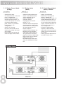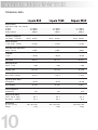
1
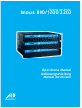
Professional Power Amplifiers
Impuls 800/1200/2200
Operational Manual
Bedienungsanleitung
Manual de Usuario
Impuls 800/1200/2200
SAFETY PRECAUTIONS
SICHERHEITSHINWEISE
MEDIDAS DE SEGURIDAD
WARNING:
ACHTUNG!:
PRECAUCIÓN:
The exclamation point inside a triangle indicates the existence of
internal components that may
affect safety when undergoing
replacement procedures.
Das Ausrufzeichen innerhalb eines
Dreiecks weist auf den Enthalt
interner Bauteile hin, dessen
Austausch sicherheitsbedingt ist.
El punto de exclamación dentro
del triángulo indica la existencia
de componentes internos que pueden ser peligrosos al ser manipulados.
The lightning and arrowhead symbol warns about the presence of
un-insulated dangerous voltage.
Das Blitzzeichen zeigt die
Gegenwart unisolierter gefährlicher Spannungen an.
El relámpago y la punta de flecha
avisa de la presencia de voltaje
peligroso sin aislar.
CAUTION
VORSICHT
PELIGRO
RISK OF ELECTRIC SHOCK
DO NOT OPEN
GEFAHR EINES ELEKTRISCHEN
SCHLAGES. NICHT ÖFFNEN
RIESGO DE DESCARGA ELÉCTRICA
NO ABRIR
To avoid fire or electrocution risk,
do not expose the unit to rain or
moisture. To avoid electric shock,
do not open the unit. No user
serviceable parts inside. In case of
disfunction, have the unit checked
by qualified agents.
Um Brand oder elektrische Schläge
zu vermeiden, setzen Sie diese
Einheit keiner starken
Luftfeuchtigkeit oder Regen aus.
Damit elektrische Schläge vermieden werden, öffnen Sie diese
Einheit nich. Bei Bedarf von
Reparaturen, wenden
Sie sich an qualifiziertes Personal.
Para prevenir riesgos de electrocución o incendio, no se deje la
unidad expuesta a la lluvia o
humedad. Para evitar electrocución no abrir la unidad. En caso
de mal funcionamiento, déjelo
revisar por técnicos cualificados.
Class I device.
Producto de Clase 1
Es handelt sich um ein Gerät der
Klasse I.
©AD-Systems, 2000
1
Impuls 800/1200/2200
INDEX
INHALTSVERZEICHNIS
ÍNDICE
0
SAFETY PRECAUTIONS
0
SICHERHEITSANWEISUNGEN
0
MEDIDAS DE SEGURIDAD
1
GENERAL INFORMATION
1.1 Introduction
1.2 Main Characteristics
1
ALLGEMEINE ANWEISUNGEN
1.1 Einleitung
1.2 Allgemeine Eigenschaften
1
INFORMACIÓN GENERAL
1.1 Introducción
1.2 Características Principales
2
CONTROLS: WHERE AND
WHAT?
2.1 Front Panel
2.2 Rear Panel
2
LOKALISIERUNG DER
FUNKTIONEN
2.1 Frontplatte
2.2 Rückseite
2
CONTROLES: DÓNDE Y COMO?
2.1 Panel Delantero
2.2 Panel Trasero
3
INSTALLATION AND
OPERATION
3.1 Connections
3.1.1 Dual Mode (Stereo)
3.1.2 Bridge Mode (Mono)
3.2 Troubleshooting
3
ANSCHLUSS- UND
INBETRIEBNAHME
3.1 Anschlüsse
3.1.1 Zweikanalmodus (Stereo)
3.1.2 Einkanalmodus (Bridge)
3.2 Problemlösung
3
INSTALACIÓN Y FUNCIONAMIENTO
3.1 Conexiones
3.1.1 Dual Mode (Estéreo)
3.1.2 Bridge Mode (Mono)
3.2 Problemas comunes
4
TECHNICAL SPECIFICATIONS
4.1 Data
4.2 Electrical diagrams
4
TECHNISCHE SPEZIFIKATIONEN
4.1 Technische Daten
4.2 Elektrische Diagramme
4 ESPECIFICACIONES TÉCNICAS
4.1 Datos Técnicos
4.2 Esquemas Eléctricos
2
Impuls 800/1200/2200
GENERAL INFORMATION
ALLGEMEINE
ANSWEISUNGEN
1.1 Introduction
1.1 Einleitung
The IMPULS Series Power
Amplifiers have been developed to
meet the highest goals in the field
of professional power amplification. Their power, distortion figures
and dynamics place them
as a reference in the industry.
Die Leistungsendstufen der Impuls
Serie sind für die höchste
Anforderungen im professionellen
Audiobereich entwickelt worden.
INFORMACIÓN GENERAL
1.1 Introducción
The IMPULS Series incorporate unique Protection Systems such as
the CRO® , an immediate load disconnection system with an exclusive design that excludes current in
the output circuit relay, and the
ICL® Clip-Limiter.
Die Impuls serie enthält einzigartige Schutzschaltungen, wie z.B.
ein anti-clip system (ICL®) oder
das automatische stromlose
Abkopp-lungssytem zum Schutz
der Lautsprecher am
Ausgangsrelais (CRO®).
1.2 Allgemeine
Eingenschaften
1.2 Main characteristics
• Trafoeinheit mit sofortigem
Hochstrom.
• Instantaneous High Flow Power
Supply.
• Hochleistungs-Toroidaltrafo.
• High Power Toroidal
Transformer.
• Leistungsmodule mit überdimensionierten Motorola®
Transistoren
Las etapas de potencia IMPULS han
sido diseñadas para lograr la más
alta calidad en el campo de la
amplificación sonora. Su potencia, cifras de distorsión y su dinámica las coloca como referencia
en la industria.
La Serie IMPULS incorpora protecciones únicas como el CRO®, un
sistema de desconexión inmediata
de corriente diseñado exclusivamente para excluir la corriente en
el relé del circuito de salida.
También integra un limitador de
clip ICL® y un SCP®
1.2 Características
Principales
• Suministro instantáneo de corriente de alta tensión.
• Transformador toroidial de alta
potencia.
• Hoher Dämpfungsfaktor.
• Módulos equipados con transistores de salida Motorola®
• High Damping Factor.
• Einzigartige Schutzschaltungen:
ICL®, SCP®, CRO®.
• Gran capacidad de amortiguamiento.
• Unique Protection Systems:
ICL® , SCP® , CRO®.
• Bridge-mode Schalter auf der
Rückseite.
• Sistemas de protección únicos:
ICL®, SCP®, CRO®.
• Bridge operation switch on rear
panel.
• Standardhöhe von zwei
Rackeinheiten.
• Interruptor en panel trasero
para empleo en “Bridge”
• 2 U Rugged Steel Chassis.
• Dicke, anodisierte
Aluminiumfrontplatte.
• Chasis resistente de 2 U.
• Oversized Motorola® output
transistors in power modules.
• Thick anodized aluminum front
panel.
• Twin Neutrik XLR Connectors.
• Slow Start System with circuit
relay based speaker protection.
• Back to front twin cooling fans.
(Impuls 800 single fan)
• Doppelte Neutrik XLR -Stecker.
• Gestufte Einschalttechnik mit
Relaisschutz für die
Lautsprecher (Softstart)
• Lüfter mit stufenlos geregelter
Geschwindigkeit. Luftaustritt
vorne.
• Elektronische Kontrolle der
Lüfter.
©AD-Systems, 2000
• Panel frontal de aluminio grueso
anodizado.
• Conectores dobles Neutrik XLR.
• Sistema de encendido lento protegido por relé para la protección de los altavoces.
• Ventilación forzada con 2 ventiladores de atrás hacia delante
(Impuls 800, 1 ventilador)
3
Impuls 800/1200/2200
CONTROLS WHERE AND
WHAT?
LOKALISIERUNG DER
FUNKTIONEN
CONTROLES, DONDE Y
COMO?
2.1 Front Panel
2.1 Frontplatte
2.1 Panel Delantero
See Figure 1
Siehe Fig. 1
Ver Figura 1
1
1
Lautstärkeregler: diese
ermöloglichen die Signalstärke
am Ausgang zu regeln.
1
Botones de atenuación del
nivel de señal: Permite el
control de atenuación individual por canal.
2
FAULT: Diese LED-Anzeige
leuchtet auf wenn das
Schutzrelais durch irgendeine
der Shutzschaltungen ausgelöst
worden ist (Kurzschluss, niedrige Impedanz, Anwesenheit von
Gleichstrom.
2
FAULT: Este LED indica que el
relé del circuito de salida esta
obedeciendo una o más ordenes de protección del amplificador: Corto circuito, impedancia, DC, encendido.
3
TEMP: Este LED indica que la
protección de temperatura
esta activada. El LED de Fault
se activará de forma simultanea indicando la desconexión
de los altavoces.
4
OK: LED que indica el funcionamiento correcto de la
unidad.
5
CLIP: Situación de clipping en
las señales de salida. El LED
se mantendrá encendido
durante 200 MS sin que este
sea su tiempo real, para permitir una detección fácil.
6
Interruptor de encendido:
Conecta la alimentación de la
etapa.
Signal attenuation level control knobs: Allows independent control of each channel’s
attenuation.
2
FAULT: This LED shows the circuit relay on the output has
opened obeying one or several
protection orders from the
amplifier: short circuit, impedance, DC, start,...
3
TEMP: This LED indicates temperature protection is active.
Fault LED will activate simultaneously indicating loudspeaker disconnection.
4
OK: LED indicating unit is functioning correctly.
5
CLIP: Clipping situation in the
outputs’ signal. The LED will
remain lit for 200 ms regardless of real clipping duration,
to allow easy detection.
3
TEMP: LED-Anzeige leuchtet
wenn eine der Überwärmungsfunktionen eintritt.
Gleichzeitig schaltet sich auch
die Anzeige “FAULT” ein.
4
OK: Anzeige für die korrekte
Funktion dieser Einheit.
5
6
7
6
Hauptstromschalter: Dieser
Schalter schaltet die
Stromzuführung der Endstufe
ein und aus.
7
Main Power LED: Die Lampe
leuchtet wenn die Endstufe
eingeschaltet ist.
Main Power Switch: Connects
the amplifier’s current feed.
Main Power: Light shows
when unit is switched on.
4
CLIP: Clip-Anzeige. Diese
Anzeige leuchtet 200 ms lang,
unabhängig von der realen
Länge des clips.
7 Main Power: Este LED indica
que hay suministro de corriente.
1 Front Panel
Impuls 800/1200/2200
2.2 Rear Panel
2.2 Rückseite
2.2 Panel Trasero
See Figure 2
Siehe Fig. 2
Ver figura 2
1
Signal Input: Female Neutrik
XLR Connectors for the amplifier’s signal input.
1
Eingangssignal: Neutrik -XLR
Buchsen.
1
Entrada de señal: Conectores
hembra Neutrik XLR para la
entrada de señal.
2
2
Signal Link: Male Neutrik
XLR Connectors for daisy chaining input signal to other
amplifiers (parallel connected
to female input connectors).
LINK: Paralele XLR-Ausgänge
zur Zusammenschaltung mehrerer Endstufen.
2
Link de Señal: Conectores
macho Neutrik XLR para encadenar señal de entrada a otras
etapas. (Conectados paralelamente a los conectores hembra de entrada).
3
Link de tierra: Este interruptor permite la desconexión
/
conexión de la toma de tierra.
4
Cable de Alimentación:
Alimentación y tierra (220V –
240V AC)
5
Conectores de altavoces:
Bornes de salida para conexión
de altavoces.
6
Dual/Single (Bridge):
Interruptor que permite seleccionar el modo de empleo.
3
4
5
6
Ground Link: This switch permits connection/disconnection
of the amp’s internal ground
to general earth.
Mains Cable: Mains and earth
main feed (220V-240V AC).
3
GROUND LINK: Ermöglicht den
Anschluss der Erdung an die
Masse der internen Schaltung.
4
Stromkabel: 220V-240 V
Wechselstrom mit
Erdanschluss.
5
Lautsprecheranschluss:
Bananenstecker-Typ zum
Anschluss externer
Lautsprecher. Der
Anschluss erfolgt über Kabel
mit entfernter Isolierung.
Speaker connectors: Output
binding posts to connect speakers.
Dual / Single (Bridge):
Operation Selection Switch.
6
Dual / Single (Bridge): Dieser
Schalter wechselt von
Zweikanaloperation zu BridgeModus.
2 Rear Panel
©AD-Systems, 2000
5
Impuls 800/1200/2200
INSTALLATION
AND OPERATION
ANSCHLUSS
UND INBETRIEBNAHME
INSTALACIÓN
Y OPERACIÓN
See figure 3
Siehe Fig 3
Ver figura 3
3.1 Connections
3.1 Anschluss
3.1 Conexiones
The Power switch must always be
on the “Off” position before plugging the amp to a properly earthed mains socket (220-240V AC).
Bevor Sie diese Einheit an eine
SHUKO-Steckdose anschliessen,
schalten Sie den Hauptstromschalter aus.
El interruptor de encendido debe
estar siempre en la posición de
apagado antes de conectar la
etapa a una fuente de corriente
adecuada (220 – 240V AC).
The input signal connected to the
amplifier can be either balanced
or unbalanced. The drawing below
shows both ways to wire an XLR
connector for the purpose.
Das Eingangssignal kann entweder
symmetrisch oder unsymmetrisch
sein.
Der Anschluss wird gemacht wie
folgt.
Balanced Signal: Connect pin 1 to
Ground, pin 2 to Signal + (hot) and
pin 3 to Signal - (cold).
Symmetrisches Signal: Die
Belegung der XLR Pins ist folgende: 1-Masse, 2- Positives Signal
(hot), 3-Negatives Signal (cold).
Unbalanced Signal: Connect Pin 1
to Ground, pin 2 to Signal and pin
3 to Ground.
Asymetrisches Signal: Die
Belegung der XLR Pins ist folgende: 1-Masse, 2- Signal, 3-Masse.
La señal de entrada del amplificador puede ser balanceada o nobalanceada. La ilustración indica
las dos formas de configurar el
cableado de un conector XLR para
desempeñar ambas funciones.
Señal Balanceada: Conecta Pin 1
a tierra, Pin 2 a señal + (hot) y Pin
3 a señal - (cold)
Señal no Balanceada: Conecta
Pin 1 a tierra, Pin 2 a señal +
(hot) y Pin 3 a tierra.
figure 3.
BALANCED WIRING
UNBALANCED WIRING
1
2
3
1
2
3
Ground
Signal +
Signal -
IMPORTANT!: If a connection is
made with an unbalanced line and
pin 3 on the XLR is not connected
to ground, a 6 dB loss occurs in
the line and only a quarter of the
amplifier power is produced.
ACHTUNG! Wenn Sie ein
Asymetrisches Signal anschliessen
und Pin 3 nicht an Masse anschliessen, erzeugt sich ein Verlust von
6dB (3/4 der Leistung der
Endstufe) am ausgangs-signal.
The amplifier provides, for each
channel, a female XLR Connector
(Signal Input) parallelled to a male
XLR to daisy chain several amplifiers with the same signal line
(LINK).
Die Endstufe rechnet mit einer
paralelen XLR-Buchse, die zum
Anschluss an weitere Endstufen
dient.
6
Ground
Signal
Ground
IMPORTANTE!: Si una conexión se
realiza con una línea no balanceada y Pin 3 no esta conectado a
tierra, habrá una perdida de 6 dB
en la línea y la etapa solo entregará una cuarta parte de su potencia.
La etapa integra por cada canal un
conector hembra XLR (entrada de
señal) paralelo a un XLR macho
para puentear varias etapas con la
misma línea de señal (LINK).
Impuls 800/1200/2200
The amplifier can operate on two
different configurations: DUAL or
BRIDGE (Dual ch. / Single ch.).
The connections for the two
modes are different.
Es gibt zwei Funktionsmöglichkeiten dieser Endstufe: DUAL und
BRIDGE (Dual ch. / Single ch.).
Die Anschlüsse sind in beiden
Fällen verschieden.
El amplificador se puede configurar de dos formas diferentes: DUAL
o BRIDGE (Dual ch. / Single ch.). La
forma de conexión es diferente
para cada modo.
3.1.1 Dual Channel Mode
(Stereo)
3.1.1 Dual Modus
(Stereo)
3.1.1 Dual Channel Mode
(Estéreo)
See Figure 4
Siehe Fig. 4
Ver figura 4
- Switch “Off” the amp.
- Set the Mode Switch on the rear
panel to “BRIDGE OFF”
- Connect the signal lines to the
female input XLR connectors on
both channels.
- Connect the speaker lines to
the corresponding binding posts
on the amplifier respecting the
polarity.
- Switch “On” the amp.
- Use the level control knob on
the front panel to adjust each
channel independently.
- Each signalling LED group will
show its corresponding channel
status.
- Schalten Sie die Endstufe aus.
- Setzen Sie den Modusschalter
auf der Rückseite auf die
Position “BRIDGE OFF”.
- Schliessen Sie beide
Eingangssignale an ihre entsprechenden XLR-Buchsen.
- Schliessen Sie beide
Lautsprecher an die entsprechenden Ausgänge an, positiv
an die rote Buchse.
- Schalten Sie die Endstufen ein.
- Benutzen Sie die Lautstärkereglung der entsprechenden
Kanäle um den gewünschten
Lautstärkepegel zu erreichen.
- Die LED-Anzeigen werden den
Status der beiden Kanäle angeben.
- Apagar el amplificador.
- Posicionar el interruptor de
Mode en el panel trasero en
“BRIDGE OFF”
- Conectar los cables de señal a
las entradas hembras XLR en
ambos canales.
- Conectar las líneas de los altavoces a sus respectivos bornes,
respetando la polaridad.
- Encender el amplificador.
- Emplear el botón de control de
atenuación situado en el panel
frontal para ajustar cada canal
de forma independiente.
- Cada grupo de LED informará
sobre el estado correspondiente
de cada canal.
4 Dual Mode
©AD-Systems, 2000
7
Impuls 800/1200/2200
3.1.2 Single Channel Mode
(Bridge)
3.1.2 Bridge Modus
(Mono)
3.1.2 Single Channel Mode
(Mono) “BRIDGE”
See Figure 5
Siehe Fig. 5
Ver figura 5
- Switch Off the amp.
- Set the Mode Switch on the rear
panel to “BRIDGE ON”
- Connect a signal line to the
female input XLR Channel “A”.
- Connect the speaker line at the
two positive (Red) binding
posts, channel “A” post becoming positive in this
configuration.
- Switch “On” the amp.
Use both control knobs at the
same level to adjust the single
amp’s output.
- Both signalling LED groups will
show the single channel mode.
- Schalten Sie die Endstufe aus.
- Setzen Sie den Modusschalter
auf der Rückseite auf die
Position “BRIDGE ON”
- Schliessen Sie das
Eingangssignal an die XLRBuchse “A” an.
- Schliessen Sie den Lautsprecher
an beide positiven Buchsen der
beiden Kanäle an, wobei positiv
der roten Buchsen des “A”Kanals entspricht.
- Schalten Sie die Endstufen ein.
- Benutzen Sie die Lautstärkereglung der beiden Kanäle um
den gewünschten Lautstärkepegel zu erreichen, wobei beide
Regler immer auf der gleichen
Position sein müssen.
- Die LED-Anzeigen werden den
Status des Ausgangkanals angeben.
- Apagar el amplificador.
- Posicionar el interruptor de
Mode en “BRIDGE ON”
- Conectar una línea de señal a la
entrada XLR hembra del canal “A”
- Conectar las líneas de los altavoces a los dos bornes positivos
(rojos). El borne del canal “A”
se convertirá en positivo en
esta configuración.
- Encender el amplificador.
Emplear los dos botones de
atenuación al mismo nivel para
ajustar el único nivel de salida
de la etapa.
- Ambos grupos de LED indicaran
el modo de canal único.
5 Bridge Mode
8
Impuls 800/1200/2200
3.2 Troubleshooting
3.2 Problemlösung
3.2 Problemas Comunes
In the event of incorrect connection or misfunctioning, the amp
will activate one or more of its
LED’s to warn about the problem.
Sollte sich irgendeine Fehlfunktion
ergeben, wird diese durch die
LED-Anzeigen auf der Frontplatte
gezeigt.
En caso de mal funcionamiento o
conexión incorrecta, uno o más
LED’s del amplificador se encenderán para alertar sobre un posible problema.
Korrektes Verhalten (fig. A).
OK (fig. A): Amplifier functions
correctly.
OK (fig. A): Amplificador funciona correctamente.
CLIP (fig. B): Das Signal “clipt”
am Ausgang.
CLIP (fig. B): Clipping situation on
the output.
Fault & Temperature (fig. C): The
amplifier has reached the maximum operational temperature.
Most common cause is that the
normal air flow is blocked by
accumulated dirt, dust or objects
leaning against the grill. Check
and clean periodically .
Protections (fig. D): Several causes can trigger this LED. The most
common are:
- Short-circuit in the speakers’
line or in the speakers themselves.
- Low Impedance: check speakers
connections or possible speaker
disfunction.
- DC in the output: the protections are activated to block
speaker output.The unit must
be repaired by a qualified technician.
- Delayed Start: As you switch on
the amp, the output to the
speakers is disconnected. After
a few seconds the amp will
connect the speakers and proceed with normal functioning.
(fig. A)
©AD-Systems, 2000
Überhitzung (fig. C): Dies kann
wegen der Verschmutzung der Luftein-oder
austritte geschehen. Es ist angebracht diese von Zeit zu Zeit zu
säubern.
Schutzschaltungen (fig. D): Der
Eingriff der Schutzschaltungen
kann sich durch folgende Gründe
auslösen:
- Kurzschluss: die Anschlusskabel
oder ggf. die Lautsprecher auf
Kurzschlüsse prüfen.
- Unangebrachte Impedanz: Die
Impedanz der Ausgänge ist zu
niedrig. Instalation auf Fehlanschlüsse testen oder ggf. Lautsprecher auf Fehler prüfen.
- Gleichstrom: Die Schutzschaltung greift ein, um die Zerstörung der Lautsprecher zu
vemeiden. Die Endstufe muss
von einem qualifiziertem
Techniker überprüft werder.
- Soft Start: Während der Inbetriebnahme der Endstufe werden die Lautsprecher zeitlich
ausgeschaltet, um einen möglichen Schaden zu vermeiden.
Nach einigen Sekunden schaltet
die Endstufe die Lautsprecher
automatisch ein.
(fig. B)
(fig. C)
CLIP (fig. B): Situación de Clip en
la salida.
Error & Temperatura (fig. C): La
etapa ha alcanzado una temperatura operacional máxima. La
causa más común de sobrecalentamiento suele ser obstrucción de
los canales de ventilación, por
acumulación de suciedad, polvo o
un objeto obstruyendo el canal de
ventilación. Comprobar y limpiar
periódicamente.
Protecciones (fig. D): Una variedad de causas puede encender los
LED’s, las más comunes son las
siguientes:
- Cortocircuito en las líneas de
altavoces o en los altavoces
mismos.
- Impedancia baja: Comprobar
conexión de altavoces o posible
error de altavoz.
- DC en la salida: Las protecciones se activan para bloquear el
canal de salida a los altavoces.
- La unidad debe ser reparada
por un técnico cualificado.
- Comienzo retardado: Al encender la etapa, la salida a los
altavoces se encuentra desconectada. Después de unos
segundos el amplificador habilitará los canales de salida y
adoptará un funcionamiento
normal.
(fig. D)
9
Impuls 800/1200/2200
TECHNICAL DATA
Impuls 800
Impuls 1200
Impuls 2200
Output Power
(Pink Noise 12dB Crest Factor)
4 Ohms . . . . . . . . . . . . . . . . .2 x 500 W . . . . . . . . . . . . .2 x 700 W . . . . . . . . . . . . . .2 x 1100 W
8 Ohms . . . . . . . . . . . . . . . . .2 x 300 W . . . . . . . . . . . . .2 x 430 W . . . . . . . . . . . . . . 2 x 660 W
Bridge 8 Ohms . . . . . . . . . . . . . .1000 W . . . . . . . . . . . . . . .1400 W . . . . . . . . . . . . . . . . 2200 W
Frequency Response
Full power +- 0.25 db . . . . .20 Hz – 20 kHz . . . . . . . . . .20 Hz – 20 kHz . . . . . . . . . . . .20 Hz – 20 kHz
Phase Response
1 watt 20 Hz – 20 kHz . . . . . . . .+-15 deg . . . . . . . . . . . . . .+- 15 deg . . . . . . . . . . . . . . .+- 15 deg
Total Harmonic Distortion
20 Hz – 20 kHz . . . . . . . . . . . . . .<0.05% . . . . . . . . . . . . . . .<0.05% . . . . . . . . . . . . . . . . .<0.05%
Crosstalk
1 kHz . . . . . . . . . . . . . . . . . . . .> 80 dB . . . . . . . . . . . . . . .> 80 dB . . . . . . . . . . . . . . . .> 80 dB
Slew Rate
. . . . . . . . . . . . . . .> 50V/µs . . . . . . . . . . . . . .>50 V/µs . . . . . . . . . . . . . . .> 50 V/µs
Damping Factor
20 Hz – 1 kHz . . . . . . . . . . . . . . . > 800 . . . . . . . . . . . . . . . .> 800 . . . . . . . . . . . . . . . . . .> 800
Voltage Gain . . . . . . . . . . . . . . .32.5 dB
Sensitivity
Max. Power/ 4 Ohms
. . . . . . . . . . . . . .32.5 dB . . . . . . . . . . . . . . . .32.5 dB
. . . . . . . . . .0.95 V . . . . . . . . . . . . . . . .1.04 V . . . . . . . . . . . . . . . . .1.45 V
Signal-to-Noise Ratio
Unweighted . . . . . . . . . . . . . . . . .98 dB . . . . . . . . . . . . . . . .99 dB . . . . . . . . . . . . . . . . .102 dB
Hum & Noise . . . . . . . . . . . . . .<0.5mV . . . . . . . . . . . . . . .<0.5mV . . . . . . . . . . . . . . . .<0.5mv
Input Impedance
Unbalanced . . . . . . . . . . . . . . . . . .47K
. . . . . . . . . . . . . . . . .47K . . . . . . . . . . . . . . . . . . .47K
Required AC Mains
230 V – 50 Hz (idle) . . . . . . . . . . . .0.5 A . . . . . . . . . . . . . . . .0.5 A . . . . . . . . . . . . . . . . . .0.5 A
Max Power / 4 Ohms . . . . . . . . . . .7.5 A . . . . . . . . . . . . . . . .9.5 A . . . . . . . . . . . . . . . . . .15 A
Dimensions
W x H x D (mm) . . . . . . . .438 x 89 x 435 . . . . . . . . . .438 x 89 x 435 . . . . . . . . . . . .438 x 89 x 435
Weight . . . . . . . . . . . . . . . . . . . .17 Kg . . . . . . . . . . . . . . . .19 Kg . . . . . . . . . . . . . . . . .23 Kg
10
Impuls 800/1200/2200
©AD-Systems, 2000
11
Impuls 800/1200/2200
12
Impuls 800/1200/2200
©AD-Systems, 2000
13
Impuls 800/1200/2200
14
General Information:
[email protected]
Sales:
[email protected]
Technical Support:
[email protected]
Tel.: + 34 - 965 841 125
Fax: + 34 - 965 843 518
V isit our website
www.ad-systems.com
100% ecological paper
Postbox 240, E-03590 ALTEA