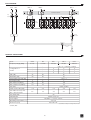
1
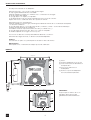
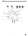
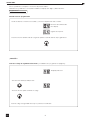
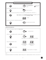
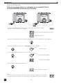
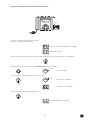
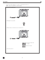
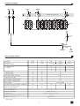
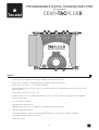
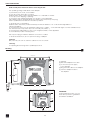
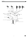
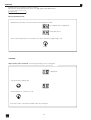
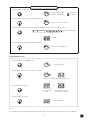
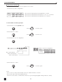
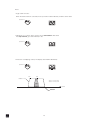
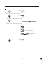
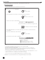
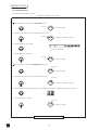
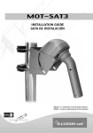
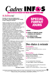
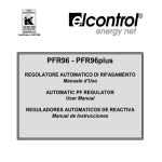
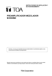
CENTRAL DIGITAL PROGRAMABLE
Manual de usuario
CENT-TACPLUS II
Tecatel
PROGRAMMABLE DIGITAL HEADEND AMPLIFIER
Instructions manual . . . . . p.19
CARACTERISTICAS
- Diseñado para canales analógicos y digitales,
- 5 entradas: B I-II / B III / 3 entradas divididas sobre 10 clusters UHF programables,
- Cada cluster puede tener de 1 a 7 canales del ancho de banda,
- Fácil programación usando el pulsador rotativo. Visionado del display de 2 dígitos y los LEDs de cada
cluster y cada entrada simplemente presionando el botón.
- La unidad puede ser bloqueada mediante código de seguridad,
- Función de "COPIA" para poder transferir toda la programación de una unidad a otra
reduciendo el tiempo de instalación,
- Filtros de gran selectividad,
- Baja figura de ruido,
- Alta ganancia y gran nivel de salida,
- Amplificador de 20 dB conmutable en cada entrada de UHF para permitir altos niveles hasta 105 dBμV.
- Amplificadores VHF-UHF de banda partida
- Regulación automática del nivel de señal o regulación manual mediante atenuador de 30 dB con
un 1 dB de paso para la ecualización exacta,
- Control de tensión selectiva en las entradas de UHF,
- Test de salida -30 dB.
INSTRUCCIONES DE SEGURIDAD
Leer con cuidado estas instrucciones antes de conectar la unidad.
El voltaje viene indicado en el adaptador.
Para prevenir fuego, corto-circuito, peligro de descargas:
No exponga la unidad a la lluvia o humedad.
Instale la unidad en un lugar seco sin filtraciones o condensaciones de agua.
No la exponga a salpicaduras.
No ponga objetos con líquido, en el aparato.
Si cae algún líquido en la carcasa accidentalmente, desconecte la corriente.
Diríjase a un tecnico cualificado antes de su puesta en marcha.
Para evitar riesgos por calentamiento:
Instale la unidad en un buen lugar y mantenga una distancia mínima de 15 cm alrededor del aparato
con suficiente ventilación.
No ponga ningún articulo como papel de periódico, manteles, cortinas... encima de la unidad que
puedan cubrir las aperturas de ventilación.
La unidad no debe ser expuesta a fuentes de calor (sol, calefacción,...).
No ponga ninguna fuente de calor, tales como velas en el aparato.
No instale el aparato en un lugar con mucho polvo.
Desconecte el cable de corriente para realizar las diferentes conexiones.
Para evitar descargas eléctricas, no abra la carcasa del adaptador.
Limpieza :
Use solamento un paño seco para limpiar la carcasa. No utilice disolventes.
Mantenimiento :
Para reparaciones o mantenimiento diríjase a personal cualificado.
MONTAJE
212.5 mm.
(5)
(3)
(1)
185 mm.
(1) Tierra
(2) Ponga el adaptador en su soporte
(3) Conecte la fuente de alimentación
al amplificador
(4) Conecte el cable de red
al adaptador
(5) Inserte el soporte del adaptador
a la carcasa del amplificador
(2)
(5)
15 cm
(4)
IMPORTANTE :
Deje un espacio mínimo de 15 cm
alrededor del producto para
garantizar la maxima ventilación.
15 cm
15 cm
15 cm
Tecatel
2
DESCRIPCION
BI-FM
BIII / DAB
UHF 1
UHF 2
UHF 3
LEDs para las
entradas y clusters
Tierra
Display de 2 Dígitos
Corriente electrica 230V~
Conector DSUB9
Rotativo / Botón de presión
Mode / Función LEDs
Salida
Test de salida
3
Tecatel
OPERACIONES
Todos los parámetros son fijados con el botón de presión rotativo.
Cada función y parámetros se muestran mediante un display de 2 dígitos y diferentes LEDs.
Programación
Entrada modo de programación
- Realice todas las conexiones necesarias y conecte el amplificador a la corriente.
La versión del software sale
en el display.
seguido de un punto.
- Presione el botón durante más de 3 segundos para acceder al sistema de programación.
3 seg.
¡ ATENCIÓN !
Cuando el código de seguridad està activado (ver "Salida modo programación" página 5) :
El display indica "0"
- Gire el botón hasta que indique "50".
- Presione el botón para confirmar el código.
Nota: el código de seguridad "50" es fijo no puede ser modificado.
Tecatel
4
Repita esta sección para ajustar todos los parámetros
- Gire el botón para seleccionar el modo deseado.
El modo está indicado
con un LED de color
verde.
= LED verde
= LED rojo
- Presione el botón para entrar al modo seleccionado.
El LED es ahora rojo.
- Dentro del modo, gire el botón para seleccionar el parámetro (entrada, cluster, canal, nivel, …)
LEDs Entradas y Clusters
I-II
III
1
2
3
4
5
6
7
8
9
10
UHF clusters
Display
- Presione el botón para confirmar la programación.
LED vuelve a ponerse verde.
Salida modo programación
- Gire el botón para seleccionar el modo Exit (Salida).
Exit
El LED està verde
- Presione el botón durante más de 3 seguntos para confirmar.
Exit
3 seg.
El LED està rojo y en el display aparecen dos guiones.
- Gire el botón para seleccionar.
o
Acceso libre
a la programación,
sin código
Acceso al modo
programación con
código "50"
- Presione el botón para confirmar.
Un punto aparece en el display.
Nota :
El amplificador pasará a modo "stand-by" y aparecerá un punto en el display pasado un minuto sin usar el botón.
5
Tecatel
PROGRAMACION CLUSTERS
Ajustar clusters / Entradas UHF
- El amplificador tiene 3 entradas UHF las cuales están divididas sobre 10 clusters.
Hay Tres posibles configuraciones :
Entrada
Número de
cluster(s)
UHF1
2
2
2
UHF2
8
7
5
UHF3
0
1
3
UHF1 los clusters están indicados por LEDs AMARILLOS n° 1 y 2
UHF2 los clusters están indicados por LEDs ROJOS n° 3,4,5,6,7,8,9 y 10
UHF3 clusters están indicados por LEDs VERDES n° 8,9 y 10
Para ajustar el número de clusters por entrada :
- Gire el botón para seleccionar el modo Split UHF (Entrada UHF).
Split UHF
El LED está verde.
Split UHF
El LED está rojo.
- Presione el botón para confirmar.
- Gire el botón para ajustar una configuración :
Display de la configuración seleccionada:
I-II
III
1
2
3
4
5
6
7
8
9
10
Entrada
Display
Número de "8.0"
"7.1"
cluster(s)
"5.3"
UHF clusters
Indicador cluster UHF1
UHF2
8
7
5
UHF3
0
1
3
Indicador cluster UHF2
Indicador cluster UHF3
- Presione el botón para confirmar.
El LED está verde.
Split UHF
Notas :
- UHF1 esta ajustado para 2 clusters, UHF2 y UHF3 estan configurados para diferentes numeros de clusters.
- Cada cluster puede ser desconectado (Función de Aparcado).
Par ejemplo, si sólo necesitas un cluster para UHF 1, ajuste el segundo cluster en el canal 00 para desconectarlo
(vea el párrafo siguiente capítulo “Ajustando canales / clusters”).
Tecatel
6
Ajustando canales / clusters
Cada cluster tiene un ancho de banda el cual puede ser programado desde 1 a 7 canales :
Para ajustar el canal o canales por cluster :
En el ejemplo siguiente el cluster 1 es ajustado para los canales 22 a 26
- Gire el botón para seleccionar el modo Select Filter (Selección Filtro).
Select Filter
Modo está indicado
con el LED de color
VERDE.
= LED verde
= LED rojo
- Presione el botón para entrar en el modo seleccionado.
Select Filter
El LED está ahora ROJO.
- Dentro del modo, gire el botón para seleccionar el cluster, que se va a ajustar.
I-II
III
1
2
3
4
5
6
7
8
9
10
UHF clusters
LED n° 1
- Presione el botón para confirmar.
Select Filter
El LED está verde.
- Gire el botón para seleccionar modo Start Channel (Canal Inicial).
Start Channel
El LED está verde.
- Presione el botón para entrar en el modo seleccionado.
Start Channel
El LED está ahora en ROJO.
- Gire el botón para seleccionar el canal inicial.
Display
- Presione el botón para confirmar.
Start Channel
El LED está verde.
- Gire el botón para seleccionar el modo Stop Channel (Canal Final).
Stop Channel
El LED está verde.
- Presione el botón para entrar en el modo seleccionado.
Stop Channel
El LED está ahora ROJO.
- Gire el botón para seleccionar el canal final.
Display
- Presione el botón para confirmar.
Stop Channel
El LED está verde.
Repita esta sección para ajustar todos los clusters.
7
Tecatel
Notas :
- Modo Monocanal
Cuando el canal de comienzo es seleccionado, el canal finalización es ajustado automáticamente con el
mismo valor.
Start Channel
- Función de aparcado :
Para desconectar el cluster, seleccione Start Channel (Canal Inicial) y ajuste canal 00.
El Stop Channel (Canal Final) ira automáticamente al canal 00.
Start Channel
- Si hay clusters solapados, el display emite un punto parpadeante de forma intermitente.
Start Channel
c22
c26
Cluster
Cluster 1 = c 22 a c 26
Cluster 2 = c 25 a c 29
canal
c25
c29
Cluster 2
Tecatel
8
Para comprobar los ajustes de canal por cada cluster.
- Gire el botón para seleccionar el modo Select Filter (Selección Filtro).
Select Filter
El LED está verde.
- Presione el botón para entrar en el modo seleccionado.
Select Filter
El LED está ahora ROJO.
- Gire el botón para seleccionar el cluster que desea comprabar.
I-II
III
1
2
3
4
5
6
7
8
9
10
UHF clusters
- El display muestra los canales ajustados.
Ejemplos :
Cluster desconectado.
Cluster ajustado al canal 22.
Cluster 22 y 26 alternativamente:
cluster ajustado desde el 22 al 26.
- Presione el botón para salir.
Select Filter
El LED está verde.
9
Tecatel
AJUSTE DE NIVEL
Los niveles son ajustados manualmente por cada entrada y/o automáticamente para los clusters.
Ajuste automático del nivel.
Los niveles de BI-II / BIII no se procesan con la función de Nivel Automático.
- Gire el botón para seleccionar el modo Auto Level (Nivel Automático).
Auto Level
El LED está en VERDE.
- Presione el botón durante más de 3 segundos para iniciar la función Auto Level.
Auto Level
El LED está ahora ROJO.
3 seg.
El nivel se ajusta automáticamente por cada cluster.
1
2
3
4
5
6
7
8
9
10
UHF clusters
El LED activado indica el cluster que actualmente
se está procesando.
El display muestra el valor de la atenuación.
Este proceso durará aprox. 1 a 2 minutos, indicando a continuación los canales y clusters
que se están ecualizando.
- Cuando el LED se ponga en VERDE, el procedimiento ha terminado.
Auto Level
El LED está VERDE
- El LED de cada cluster muestra el estado de la ecualización.
1
2
3
4
5
6
7
8
9
10
UHF clusters
Apagado: cluster desconectado
Encendido: Nivel correcto
Parpadeo lento: Nivel bajo
Parpadeo rápido: Nivel demasiado fuerte
Notas:
- El ajuste automático fija el nivel de salida del cluster a 90 dBμV (para una señal de entrada entre 50 y 80 dBμV).
Si el nivel de entrada es inferior a 50 dBμV, el LED parpadeará lentamente después del procedimiento de
ajuste automático.
Si el nivel de entrada es mayor a 80 dBμV, el LED parpadeará rápidamente.
Reajustar el nivel de entrada (atenuación o ganancia) si fuera necesario.
- El atenuador general se fija a 0 dB después del ajuste automático.
Se puede reajustar en un rango de -9 a +10 dB para obtener un nivel de salida entre 81 y 100 dBuV
(ver "Ajuste general del nivel de UHF).
- El nivel de cada cluster se puede ajustar de forma independiente (ver "Ajuste manual del nivel")
IMPORTANTE: La indicación de los 8 LEDs no cambiará después del ajuste manual de los clusters.
Tecatel
10
Cuando el nivel de los clusters ha sido ecualizado individualmente, el nivel general de las señal de UHF
pueden ser ajustados en pasos de 1 dB desde +10 dB hasta -9 dB.
Ajuste general del nivel de UHF.
Para ajustar los niveles generales de UHF.
Seleccione todos los clusters.
- Gire el botón para seleccionar el modo Select Filter (Selección Filtro).
Select Filter
El LED está verde.
- Presione el botón para entrar en el modo seleccionado.
Select Filter
El LED está ahora ROJO.
- Gire el botón para seleccionar toda la UHF.
I-II
III
1
3
2
4
5
6
7
8
9
10
UHF Clusters
Todos los LEDs
están activados
- Presione el botón para confirmar.
Select Filter
El LED está verde.
- Gire el botón para seleccionar el modo Manual Level (Nivel Manual).
Manual level
El LED está verde.
- Presione el botón para entrar en el modo seleccionado.
Manual Level
El LED está ahora ROJO.
- Gire el botón para ajustar el nivel general, variable desde +10 dB hasta -9 dB.
- Presione el botón para confirmar.
Manual Level
El LED está verde.
11
Tecatel
AJUSTE DE NIVEL
Los niveles son ajustados manualmente por cada entrada y / o automáticamente para los clusters.
Ajuste manual del nivel.
Para ajustar manualmente el nivel.
- Seleccione la entrada o cluster deseado.
Ejemplo : ajustar el nivel de BI-II.
- Gire el botón para seleccionar el modo Select Filter (Selección Filtro).
Select Filter
El LED está verde.
- Presione el botón para entrar en el modo seleccionado.
Select Filter
El LED está ahora ROJO.
- Gire el botón para seleccionar BI-II.
I-II
III
1
2
3
4
5
6
7
UHF clusters
LED está activado
- Presione el botón para confirmar.
Select Filter
El LED está verde.
- Gire el botón para seleccionar el modo Manual Level (Nivel Manual).
Manual Level
El LED está verde.
- Presione el botón para entrar el modo seleccionado.
Manual Level
El LED está ahora ROJO.
- Gire el botón para ajustar el nivel manualmente, se puede variar desde 20 dB hasta 0 dB
(30 dB hasta 0 dB para clusters).
- Presione el botón para confirmar.
Manual Level
El LED está verde.
Repita esta sección para ajustar todos los niveles
Tecatel
12
8
9
10
Para desactivar el amplificador de entrada UHF.
- Seleccione la entrada que debe atenuarse.
- Gire el botón para selecctionar el modo Select Filter (Selección Filtro).
Select Filter
El LED está verde.
- Presione el botón para entrar en el modo seleccionado.
Select Filter
El LED está ahora rojo.
- Gire el botón continuamente hasta acceder al
grupo de filtros de la entrada UHF correspondiente.
2
1
2
3
4
5
1
6
7
8
9
10
3
Todos los LED están activados
- Presione el botón para confirmar.
Select Filter
El LED está verde.
- Gire el botón para seleccionar el modo Manual Level (Nivel manual).
Manual Level
El LED está verde.
- Presione el botón para entrar en el modo seleccionado.
Manual Level
El LED está ahora rojo.
- Gire el botón para desactivar el amplificador de 20 dB.
En posición 'OFF'
la señal de entrada
se reduce en 20 dB.
- Presione el botón para confirmar.
Manual Level
El LED está verde.
13
Tecatel
FUNCION COPIA
Esta función permite transmitir todos los ajustes desde una unidad a otra unidad o importar desde el
módulo de memoria (opcional).
Todas las acciones deben ser realizadas en la unidad ESCLAVA.
La unidad MAESTRA permanece en Stand-by.
Maestra
Datos
- Conecte la unidad Maestra y la Esclava con un cable DSUB9 macho/macho cruzado.
- Después conecte la corriente de las unidades.
La version del software aparece en el display,
seguido de un punto.
- Presione el botón durante más de 3 segundos para entrar en el modo de programación (ver página 4).
3 seg..
- Gire el botón para seleccionar el modo Data Import (Importación de Datos).
Data Import
El LED está verde.
- Presione el botón para entrar en el modo seleccionado.
Data Import
El LED está ahora ROJO.
3 seg..
AL aparece en el display.
- Presione el botón para confirmar Data Import.
Un punto aparece en el display
Nota :
Si ocurre un problema durante la transmisión de datos el display mostrará un mensaje de error :
Los posibles causas son: el cable no es el adecuado, no hay cable, mal contacto en los pins...
Tecatel
14
Copia desde el módulo de memoria STICK-TACPLUS (opcional).
Datos
Tecatel
PC
Memor y
Posi tion
Orange: Standby
Green: Import OK
Red: Import error
D ata I mpor t
- Conecte el Módulo de Memoria a la unidad
- Después conecte la unitad principal.
La version del software aparece en el display,
seguido de un punto.
- Presione el botón durante más de 3 segundos para entrar en el modo de programación (ver página 4).
3 seg.
- Gire el botón para seleccionar el modo Data Import (Importación de Datos).
Data Import
El LED está verde.
- Presione el botón para entrar en el modo seleccionado.
Data Import
El LED está ahora ROJO.
3 seg.
'AL' aparece en el display.
- Presione el botón para confirmar Data Import.
Un punto aparece en el display,
15
Tecatel
RESET GENERAL
Esta función puede reestablecer los clusters y los atenuadores al valor cero.
Nota: Código de seguridad non está reseteado
- Desconecte el cable de red.
- Mantenga el botón pulsado.
- Hasta que haya conectado de nuevo el cable de red.
La versión del software sale
en el display
seguido de un punto.
- Suelte ahora el botón.
Tecatel
16
DIAGRAMA DE BLOQUES
BI-II
BIII
UHF 1
UHF 2
DC
UHF 3
DC
DC
Amplificador de entrada 20 dB
Att.
20 dB
1
2
3
4
5
6
7
8
9
10
Att.
30 dB
Nivel Auto
At. general
20 dB
V
U
SALIDA
Test
-30 dB
ESPECIFICACIONES TECNICAS
BI-FM
BIII
UHF 1
UHF 2
UHF 3
Rango de
frecuencia (MHz)
47-108
174-240
470-862
470-862
470-862
-
-
Configuratión de
los clusters
-
-
2
8
0
-
-
2
7
1
-
-
2
5
3
Ganancia (dB)
35
40
45
Atenuador (dB)
20
20
30
Entradas
8-56 (1 a 7 canales / cluster)
Nivel general ajus. UHF (dB)
-
-
+10 a -9
Figura de ruido (dB)
5
5
6
Nivel máximo Entrada (dBμV)
80
80
105
Nivel máximo Salida (dBμV)*
116
116
116
Selectividad
10 dB / 10 MHz
-
Pérdida de retorno Entrada / Salida (dB)
>10
>10
>10
>10
>10
Paso de corriente selectivo
24V / 100 mA en total
No
No
Si
Si
Si
Test de salida (dB)
-30
Transferencia datos
DSUB9 conector
Alimentación
230 V~ / 15 V DC / 30 VA
Temperatura de funcionamiento (c°)
-5 a +50
Dimensiones (mm)
265 x 220 x 95
Todas las especificaciones pueden ser sujetos a cambios sin previo aviso.
* -54 dB / IM3
17
Tecatel
DECLARACIÓN DE CONFORMIDAD
DECLARATION OF CONFORMITY
TECATEL, S.L.
Dirección / Address:
C/Lletra B, nº1.
Polígono Industrial Pardines
46722 Beniarjó
Valencia (Spain)
B-46940524
CIF/VAT:
Declara bajo su responsabilidad la conformidad del producto:
Declares under its responsibility the conformity of the product:
TECATEL CENT-TACPLUS I I
TECATEL CENT-TACPLUS II
Amplificador programable
Programmable Amplifier
Al que se refiere esta declaración con las normas y estándares siguientes:
To which this declaration refers with the following norms and standards
EMC:
LVD:
EN50083-2, del 2006
EN61000-3-2, del 2006 +A1/2009 +A2/2009
EN61000-3-3, del 2008
EN61065, del 2002
EN50083-1, del 09.1993
De acuerdo con las disposiciones de las Directivas 2006/95/EC de Baja Tensión y 2004/108/EC de Compatibilidad
Electromagnética del Parlamento Europeo y del Consejo.
According to the provisions set forth in the European Parliament and Council Directives 2006/95/EEC LVD (Low Voltage) and
2004/108/EEC EMC (Electromagnetic Compatibility).
Beniarjó, 11/10/2011
Maurizio Porsia
Responsable de producto
Este producto cumple con los requisitos de las directivas 73/23/CEE y 89/336/CEE
modificadas por la directiva 93/68/CEE.
De acuerdo con la directiva Europea WEEE sobre gestión de residuos de materiales
eléctricos y electrónicos, este producto debe tener un tratamiento particular en su desecho.
La recogida selectiva de desechos ayuda a conservar los recursos naturales y a garantizar
un reciclaje que proteja la salud humana y el medioambiente.
Para obtener información adicional sobre los lugares en los que puede deshacerse de
equipos eléctricos y electrónicos, póngase en contacto con las autoridades competentes
de su localidad o con el vendedor que le suministró el producto.
Tecatel
18
PROGRAMMABLE DIGITAL HEADEND AMPLIFIER
Instructions manual
Tecatel
CENT-TACPLUS II
FEATURES
- Designed for both digital and analogue Satellite and Terrestrial channels,
- 5 inputs: B I-II / B III and 3 UHF inputs splitted over 10 UHF programmable clusters,
- Each cluster can have 1 to 7 channels bandwidth,
- Easy programming by using one rotary / push button viewed on 2 digits display and LEDs for each cluster
and each input,
- Unit can be locked by security code
- 'COPY' function in order to transfer all settlements from one unit to another reducing time of installation,
- High selectivity filters,
- Low noise figure amplifiers,
- High gain and output power,
- High UHF input levels up to 105 dBμV by switchable 20 dB input amplifier
- VHF-UHF split band amplifiers,
- Automatic leveling of signal or manual by attenuator with 1 dB step for accurate equalization
- Selectable remote power on UHF inputs,
- -30 dB Test output.
19
Tecatel
SAFETY INSTRUCTIONS
Read carefully these instructions before connecting the unit.
The operating voltage is indicated on the adapter.
To prevent fire, short circuit, shock hazard:
Do not expose the unit to rain or moisture.
Install the unit in a dry location without infiltration or condensation of water.
Do not expose it to dripping or splashing.
Do not place objects filled with liquids, such as vases, on the apparatus.
If any liquid should accidentally fall into the cabinet, disconnect the power plug.
Refer to qualified technician before it's further operation.
To avoid any risk of overheating:
Install the unit in a well aery location and keep a minimum distance of 15 cm around the apparatus for
sufficient ventilation.
Do not place any items such as newspapers, table-cloths, curtains ... on the unit that might cover the ventilation holes.
The unit must not be exposed to any source of heat (sun, heater,...).
Do not place any naked flame sources, such as lighted candles, on the apparatus.
Do not install the product in a dusty place.
Pull out power plug to make the different connections of cables.
To avoid electrical shock, do not open the housing of adapter.
Cleaning :
Only use a dry soft cloth to clean the cabinet. Do not use solvent.
Servicing :
For repairing and servicing refer to qualified personnel.
Mounting
212.5 mm.
(5)
(3)
(1)
185 mm.
(1) Earthing
(2) Place the adapter in its holder
(3) Connect the power supply
to the amplifier
(4) Plug the mains cable to the adapter
(5) Click the adapter holder to
the amplifier
(2)
(5)
15 cm
(4)
IMPORTANT :
Leave a minimum space of 15 cm.
around the product to guarantee
a maximum ventilation.
15 cm
15 cm
15 cm
Tecatel
20
DESCRIPTION
BI-FM
BIII / DAB
UHF1
UHF2
UHF3
LEDs for
Inputs and Clusters
Grounding
2 Digit Display
Mains 230-240V~
DSUB9 Connector
Rotary / Push Button
Mode / Function LEDs
Output
Test Output
21
Tecatel
OPERATION
All parameters are set with the rotary push button.
Each function and parameters are shown on 2 digits display and different LEDs .
Programming
Enter programming mode
- Make all the necessary connections and connect amplifier to mains.
The software version is displayed,
followed by a dot.
- Push on the rotary button for more than 3 seconds to enter into programming mode.
3 sec.
ATTENTION !
When security code is activated (see "Exit programming mode" on page 29)
23) ::
is displayed.
- Turn the button to display "50"
- Push the button to confirm the code.
Note: the security code "50" is fixed and can not be changed.
22
Tecatel
28
Repeat this section to set all parameters
- Turn the button to select the desired mode.
Mode is indicated with
a GREEN colored LED.
= green LED
= red LED
- Push the rotary button to enter the selected mode.
The LED is now RED colored.
- Inside the mode, turn the button to select the parameter (input, cluster, channels, level...)
Input and Cluster LEDs
I-II
III
1
2
3
4
5
6
7
8
9
10
UHF Clusters
Display
- Push the button to confirm the parameter setting.
LED returns to a GREEN color.
Exit programming mode
- Turn the button to select Exit mode.
Exit
The LED is green.
- Push the button more than 3 seconds to confirm.
Exit
3 sec.
The LED is red and 2 dashes are displayed
- Turn the button to select
or
Free access
to progamming
mode
Access to
progamming mode
with security code "50"
- Push the button to confirm.
A dot is displayed
Note :
The amplifier will go in "stand-by" and will display a dot after 1 minute if the rotary / push button is not activated.
23
29
Tecatel
CLUSTER PROGRAMMING
Setting clusters / UHF input
- The amplifier has 3 UHF inputs which are splitted over 10 clusters.
There are three possible configurations :
Input
Number of
cluster(s)
UHF1
2
2
2
UHF2
8
7
5
UHF3
0
1
3
UHF1 clusters are indicated by the YELLOW LEDs n° 1 and 2.
UHF2 clusters are indicated by the RED LEDs n° 3, 4, 5, 6, 7, 8, 9 and 10.
UHF3 clusters are indicated by the GREEN LEDs n° 8, 9 and 10.
To set the number of cluster(s) per input :
- Turn the button to select Split UHF mode.
Split UHF
The LED is green.
Split UHF
The LED is red.
- Push the button to confirm.
- Turn the button to set one configuration :
Display of selected configuration :
I-II
III
1
2
3
4
5
6
7
8
9
10
Input
Number of
cluster(s)
UHF Clusters
UHF1 cluster indicator
Display
"8.0"
"7.1"
"5.3"
UHF2
8
7
5
UHF3
0
1
3
UHF2 cluster indicator
UHF3 cluster indicator
- Push the button to confirm.
The LED is green.
Split UHF
Notes:
- UHF 1 is set for 2 clusters, UHF 2 and UHF 3 are set for different number of clusters.
- Each cluster can be switched off (Park function).
Set the non used cluster on channel 00 to switch it off (see following paragraph "Setting channels / cluster").
Tecatel
24
Setting channels / cluster
Each cluster has a bandwidth which can be programmed from 1 to 7 channels :
To set the channel(s) per cluster :
In the following example cluster 1 is set for channel 22 to channel 26.
- Turn the button to select the Select Filter mode.
Select Filter
= green LED
Mode is indicated with
a GREEN colored LED.
= red LED
- Push the rotary button to enter the selected mode.
Select Filter
The LED is now RED colored.
- Inside the mode, turn the button to select the cluster to be set.
I-II
III
1
2
3
4
5
6
7
8
9
10
UHF Clusters
LED n° 1
- Push the button to confirm.
Select Filter
The LED is green.
- Turn the button to select the Start Channel mode.
Start Channel
The LED is green.
- Push the rotary button to enter the selected mode.
Start Channel
The LED is now RED colored.
- Turn the button to select the start channel
Display
- Push the button to confirm.
Start Channel
The LED is green.
- Turn the button to select the Stop Channel mode.
Stop Channel
The LED is green.
- Push the rotary button to enter the selected mode.
Stop Channel
The LED is now RED colored.
- Turn the button to select the stop channel
Display
- Push the button to confirm.
Stop Channel
The LED is green.
Repeat this section to set all clusters
25
Tecatel
Notes :
- Single channel mode :
When the Start Channel is selected, the Stop Channel is automatically set at the same value.
Start Channel
- Park function : to switch off the cluster, select Start Channel and set 00.
The Stop Channel goes automaticaly to 00.
Start Channel
- If there are overlapping clusters, the display dots will blink alternately.
Start Channel
ch22
ch26
cluster 1
Cluster 1 = ch 22 to ch 26
Cluster 2 = ch 25 to ch 29
channel
ch25
ch29
cluster 2
Tecatel
26
To check the channel settings of each cluster :
- Turn the rotary button to select Select Filter.
Select Filter
The LED is GREEN.
- Push the rotary button to enter the selected mode.
Select Filter
The LED is now RED colored.
- Turn the button to choose the cluster to be checked.
1
2
3
4
5
6
7
8
9
10
UHF Clusters
- The display shows the channels which have been set.
Examples :
Cluster is parked.
Cluster is set to channel 22.
Blinking 22 and 26:
cluster is set from 22 to 26.
- Push the button to exit.
Select Filter
The LED is GREEN.
27
Tecatel
LEVEL ADJUSTMENT
Levels are manually set for each input and / or automatically for the UHF clusters.
Automatic level setting
The levels of BI-II / BIII are not processed in the Auto Level function.
- Turn the button to choose the Auto Level.
Auto level
The LED is GREEN.
- Push the rotary button for more than 3 seconds to start the Auto Level function.
Auto level
The LED is now RED colored.
3 sec.
The level of each cluster is set automatically.
1
2
3
4
5
6
7
8
9
10
UHF Clusters
The actived LED indicates the cluster which is being processed.
The display shows the value of attenuation.
This procedure will take about 1 to 2 minutes, depending on the number of channels and clusters
to be equalized.
- When the LED is GREEN, the procedure is finished.
Auto level
The LED is GREEN.
- Each cluster's LED shows the status of equalization.
1
2
3
4
5
6
7
8
9
10
UHF Clusters
LED off : parked cluster
LED on : correct level
LED blinking slowly : signal is too weak
LED blinking rapidly : signal is too strong
Notes :
- The automatic level adjustment set the output level of the clusters at 90 dBμV
(for an input level between 50 to 80 dBμV).
If the input level is less than 50 dBμV, the LED will blink slowly after the automatic level adjustment.
If the input level is higher than 80 dBμV, the LED will blink rapidly after the automatic level adjustment.
Adjust the input level (attenuation or amplification) if necessary.
- The general attenuator is fixed to 0 after the automatic level adjustment. It can be adjusted from -9 to +10
to get a level between 81 to 100 dBμV (see "General UHF level setting").
- The level of each cluster can be adjusted independently (see "manually level setting).
IMPORTANT : the 10 LEDs indication will not be changed after setting the levels manually.
Tecatel
28
After automatic level setting procedure, the general level of the UHF signals (clusters and the UHF part of the
VHF-UHF input) can be adjusted from +10 dB to -9 dB in steps of 1 dB.
General UHF level setting
- Select all the clusters.
- Turn the button to choose the Select Filter mode.
Select Filter
The LED is green.
- Push the rotary button to enter the selected mode.
Select Filter
The LED is now RED colored.
- Turn the button to select all UHF.
I-II
III
1
2
3
4
5
6
7
8
9
10
UHF Clusters
All LEDs are activated
- Push the button to confirm.
Select Filter
The LED is green.
- Turn the button to select the Manual Level mode.
Manual Level
The LED is green.
- Push the rotary button to enter the selected mode.
Manual Level
The LED is now RED colored.
- Turn the button to set the general level, variable from +10 dB to -9 dB.
- Push the button to confirm.
Manual Level
The LED is green.
29
Tecatel
Manually level setting
To set manually the level.
- Select the desired input or cluster.
Example : setting the level of BI-II
- Turn the button to choose the Select Filter mode.
Select Filter
The LED is green.
- Push the rotary button to enter the selected mode.
Select Filter
The LED is now RED colored.
- Turn the button to select BI-II.
I-II
III
1
2
3
4
5
6
7
8
UHF Clusters
LED is activated
- Push the button to confirm.
Select Filter
The LED is green.
- Turn the button to select the Manual Level mode.
Manual Level
The LED is green.
- Push the rotary button to enter the selected mode.
Manual Level
The LED is now RED colored.
- Turn the button to set manually the level, variable from 20 dB to 0 dB (30 dB to 0 dB for clusters).
- Push the button to confirm.
Manual Level
The LED is green.
Repeat this section to set all levels
Tecatel
30
9
10
To switch off the UHF input amplifier.
- Select the input to be attenuated.
- Turn the button to select the Select Filter mode.
Select Filter
The LED is GREEN.
- Push the rotary button to enter the selected mode.
Select Filter
The LED is now RED colored.
- Turn the button to select the input.
Turn continuously the button through every cluster
to have access to the input selection.
2
1
2
3
4
5
1
6
7
8
9
10
3
All LEDs of selected input are activated
- Push the button to confirm.
Select Filter
The LED is GREEN.
- Turn the button to select the Manual Level mode.
Manual Level
The LED is GREEN.
- Push the rotary button to enter the selected mode.
Manual Level
The LED is now RED colored.
- Turn the button to switch off the 20 dB amplifier.
In 'OFF' position
the input signal is
20 dB attenuated.
- Push the button to confirm.
Manual Level
The LED is GREEN.
31
37
Tecatel
COPY FUNCTION
This function allows to transmit all settings from one unit to another unit or import from the memory stick (optional).
All actions have to be done on the SLAVE unit.
The MASTER unit remains in Stand-by.
SLAVE
MASTER
Data
- Connect master and slave unit with a DSUB9 male/male crossed cable.
- Then connect mains to the units.
The software version is displayed,
followed by a dot.
- Push on the rotary button for more than 3 seconds to enter into programming mode (See page 22).
3 sec.
- Turn the button to select the Data Import mode.
Data Import
The LED is green.
- Push the rotary button to enter the selected mode.
Data Import
The LED is now RED colored.
3 sec.
AL is displayed
- Push the rotary button to confirm Data Import.
A dot is displayed
Note :
If a problem occurs during data transmission the display will show an error message :
Possible causes are : wrong type of cable, no cable, bad pin contacts.
Tecatel
32
Copy from Memory Stick model STICK-TACPLUS (optional).
Data
Tecatel
TAC PLUS
PC
Memor y
Posi tion
Oran ge: Standby
Green: Impor t OK
Red: Import error
D ata I mpor t
- Connect the Memory Stick to the unit.
- Then connect the mains to the unit.
The software version is displayed,
followed by a dot.
- Push on the rotary button for more than 3 seconds to enter into programming mode (see page 22).
3 sec.
- Turn the button to select the Data Import mode.
Data Import
The LED is green.
- Push the rotary button to enter the selected mode.
Data Import
The LED is now RED colored.
3 sec.
AL is displayed
- Push the rotary button to confirm Data Import.
A dot is displayed.
33
Tecatel
GENERAL RESET
This function can reset all clusters and attenuators to zero.
Note: security code is not reset.
- Disconnect the mains power.
- Keep on pressing the button,
- until the mains is connected again.
The software version is now displayed
followed by a dot.
- Release the button.
Tecatel
34
BLOCK DIAGRAM
BI-II
BIII
UHF 1
UHF 2
UHF 3
DC
DC
DC
20 dB input amplifier
Att.
20 dB
1
2
3
4
5
6
7
8
9
10
Att.
30 dB
Auto Level
General
Att. 20 dB
V
U
Test
-30 dB
OUT
TECHNICAL SPECIFICATIONS
Inputs
BI-FM
BIII
UHF 1
47-108
174-240
470-862
-
-
Configuration of
-
-
2
8
0
clusters
-
-
2
7
1
2
5
3
Frequency range (MHz)
UHF 2
UHF 3
470-862
470-862
8-56 (1 to 7 channels / cluster)
-
-
Gain (dB)
35
40
Attenuator (dB)
20
20
30
-
-
+10 to -9
General UHF level adj. (dB)
45
Noise figure (dB)
5
5
6
Max. input level (dBμV)
80
80
105
Max. output level (dBμV)*
116
116
Selectivity
Return loss IN / OUT (dB)
Selectable remote power
24V / 100 mA in total
116
10 dB / 10 MHz
>10
>10
>10
>10
>10
No
No
Yes
Yes
Yes
-30
Test output (dB)
Data transfert
DSUB9 connector
Power supply
230-240 V~ / 15 V DC / 30 VA
-5 to +50
Operating temperature (c°)
265 x 220 x 95
Dimensions (mm)
Specifications are subject to change without notice.
* -54 dB / IM3
35
Tecatel
This product complies with the requirements of the Directives 73/23/CEE and 89/336/CEE
amended by Directive 93 / 68 / EEC.
According to the WEEE (Waste electrical and electronic equipment) EU Directive,
do not dispose of this product as household waste or commercial waste.
Waste electrical and electronic equipment should be appropriately collected and
recycled as required by practices established for your country.
For information on recycling of this product, please contact your local authorities,
your household waste disposal service or the shop where you purchased the product.
10/11
www.tecatel.com
Tecatel