1
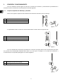
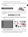
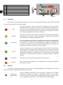
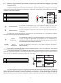
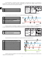
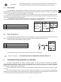
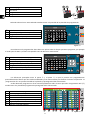
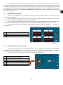
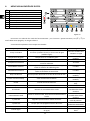
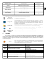
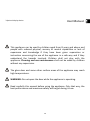
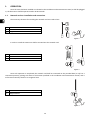
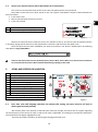
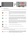
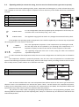
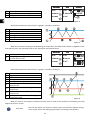
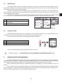
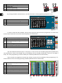
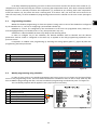
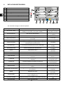
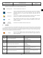
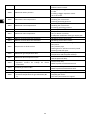
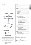
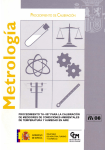
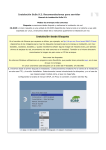
Manual de usuario. User manual. UNE EN 14785 ÍNDICE 1.- CONEXIÓN Y FUNCIONAMIENTO. 2.- EXPLICACIÓN DE LOS ICONOS Y PANTALLA. 3.- PROGRAMACIONES ENCENDIDO Y/O APAGADO. 4.- MENÚ VISUALIZACIÓN DE DATOS. 5.- ALARMAS. Páginas 3-4 Páginas 4-8 Páginas 8-10 Páginas 11-12 Páginas 12-13 INDEX 1.- OPERATION. 2.- ICONS AND SCREEN EXPLANATION. 3.- POWER ON/OFF PROGRAMMING. 4.- DATA VISUALISATION MENU. 5.- ALARMS. Pages Pages Pages Pages Pages 25/06/2.015 1 15-16 16-20 20-22 23-24 24-25 Manual de usuario. *Dispositivo visualizador opcional. Este aparato pueden utilizarlo niños con edad de 8 años y superior y personas con capacidades físicas, sensoriales o mentales reducidas o falta de experiencia y conocimiento, si se les ha dado la supervisión o formación apropiadas respecto al uso del aparato de una manera segura y comprenden los peligros que implica. Los niños no deben jugar con el aparato. La limpieza y el mantenimiento a realizar por el usuario no deben realizarlos los niños sin supervisión. El cristal de la puerta y algunas superficies del aparato pueden alcanzar altas temperaturas. ¡ATENCIÓN!: no abrir la puerta durante el funcionamiento del aparato. Lea con atención este manual de instrucciones antes de utilizar el aparato. Sólo así, podrá obtener las mejores prestaciones y la máxima seguridad durante su uso. 2 1. CONEXIÓN Y FUNCIONAMIENTO. Una vez instalada la estufa según se indica en el manual de instalación y mantenimiento procederemos a enchufar la estufa, la electrónica estará operativa en 30-40 segundos. 1.1. Conjunto tarjeta de red. Montaje y conexión. Dentro de la caja de la tarjeta de red tendremos los elementos necesarios para su montaje. Antena. Tarjeta de red. Base de conexión con imán. Figura 1 Lo que debemos hacer es montar la antena enroscando la misma sobre la tarjeta de red. Antena. Tarjeta de red. Tarjeta de red y antena montadas. Figura 2 Una vez realizada dicha operación procederemos a conectar la tarjeta sobre la base suministrada (sólo tiene una posición de conexionado) ubicando dicha base en la zona que se indique en el manual de instalación y mantenimiento, ésta quedará fijada gracias a su base magnética. Sentido de conexión del conjunto. Base magnética. Figura 3 3 1.2. Conexión a estufa desde cualquier dispositivo que permita conexión Wifi. Lo primero que necesitaremos es conocer la identificación de la red wifi de la estufa (SSID) y la contraseña de dicha red. Esta información se encuentra en una pegatina similar al ejemplo de la figura 4, dicho adhesivo puede localizarse en 3 lugares: • CPU de la estufa. • Próxima a la pegatina con el nº de serie de la máquina. • En el manual de usuario. Identificación red Wi-Fi estufa (SSID). Contraseña red Wi-Fi estufa (PWD). Figura 4 Debemos buscar y establecer conexión con la red Wifi de la estufa, para ello debemos introducir la contraseña mostrada en la pegatina, respetando todos los caracteres alfanuméricos de la contraseña, así como mayúsculas y minúsculas. Con la conexión establecida, introducir en el navegador web de nuestro dispositivo, la dirección URL: http://192.168.3.1 Figura 5 Si el dispositivo con conexión WIFI es utilizado con distintas redes (estufa, wifi de casa, wifi trabajo, etc), debemos asegurarnos que cuando hagamos algo en la estufa, debemos estar conectados a la red wifi de la misma. 2. EXPLICACIÓN DE LOS ICONOS Y PANTALLA. Pantalla principal. Mensaje de seguridad. (N o Axx)** Encendido / apagado. Configuración. Selección combustible, zona horaria e idioma. Incremento-decremento combustible o tempera. Programación de encendido / apagado. Temperatura interior vivienda. Fecha y hora actual. Modo de funcionamiento (P, T o E)* * Punto 2.5. Potencia, temperatura o emergencia. ** Alarmas (Axx). 2.1. Figura 6 Selección de combustible, idioma y zona horaria (para utilizar esta función la estufa debe estar apagada y sin indicar ninguna alarma). Actualmente disponemos de una selección rápida del tipo de combustible a utilizar. Aún así debemos consultar con nuestro distribuidor las características del combustible a utilizar así como la necesidad, si la hubiese, del montaje de algún accesorio mecánico. El combustible seleccionado aparecerá resaltado en rojo. Del mismo modo en este menú podremos seleccionar también el idioma y la zona horaria. 4 Selección combustible, zona horaria e idioma. Hueso de aceituna. Cáscara de almendra. Pellet. Selección idioma. Zona horaria. Regreso a pantalla principal. Figura 7 2.2. Encendido. Para realizar el encendido debemos pulsar en el icono de la pantalla principal, su color cambiará a medida que pasa por las diferentes fases de encendido. Rojo En primera instancia y cuando la estufa está apagada y lista para encender visualizaremos el mencionado icono en color rojo. Pulsandolo nos preguntará en una nueva ventana si deseamos encender la estufa, si aceptamos la electrónica hará una breve verificación de motores y depresión de aire y procederá a realizar el encendido, cambiando el icono de rojo a amarillo. Amarillo Cuando el icono pasa a color amarillo nos indica que la estufa está realizando un encendido con el extractor, caída de combustible y resistencia de encendido funcionando para conseguir la combustión inicial. Azul celeste Una vez conseguimos una diferencia de temperatura respecto a la registrada en el momento del encendido el icono cambiará a color azul celeste indicando que se encuentra en proceso de precalentamiento, apagará la resistencia de encendido y se realizará un proceso totalmente automatizado para conseguir una combustión adecuada para el posterior funcionamiento. Verde Cuando la temperatura en la salida de gases alcance los 100°C y transcurran 6 minutos desde el encendido el icono cambiará color verde lo que nos indica que ha finalizado el proceso de encendido y tendremos acceso al ajuste de caída de combustible o regulación de temperatura. En el caso de que no consiga dicha temperatura en 15 minutos pasará a indicar la alarma 99 (A099). Ver tabla de alarmas. Azul marino Naranja 2.3. Indica que está a la espera de la programación. Leer punto 2.4 Dicho icono viene acompañado con la señalización del mensaje de seguridad. Véase punto 5 alarmas. Apagado. Para realizar el apagado pulsaremos en el icono de encendido/apagado y nos preguntará en una nueva ventana si deseamos apagar la estufa, aceptamos la acción. Rojo/blanco (parpadeando) El icono parpadeará alternando el rojo con blanco y procederá a un apagado automático comandado por tiempo y temperatura, deben transcurrir como mínimo 15 minutos y la temperatura de salida de gases ser igual o inferior a 80°C. Si no se cumplen estas condiciones no se fínalizará la acción de apagado. 5 2.4. Modos de funcionamiento (para utilizar esta función la estufa debe estar apagada y sin indicar ninguna alarma). La electrónica dispone de tres modos de funcionamiento, potencia, temperatura y emergencia. Para localizar la ubicación de dicho icono podemos ver la figura 8. A continuación se explican de forma gráfica como seleccionar cualquiera de los modos indicados: Icono de acceso a configuración. Selección de modo de funcionamiento. Distintos modos de funcionamiento. Regreso a menú anterior. Configuración del modo temperatura. Regreso a pantalla principal. Figura 8 P Modo P: Potencia. Es el modo de configuración que va por defecto de fábrica. En este nivel podremos seleccionar con los iconos de + y – mas o menos caída de combustible. 9 Modo P: Potencia. El rango de regulación va del nivel 1 al 9, siendo el 9 el nivel de caída máxima de combustible. Si configuramos el modo de trabajo en temperatura la P será sustituída por una T, sólo debemos configurar este modo si tenemos la sonda de ambiente conectada: Modo T: Temperatura. T 21.5 Modo T: Temperatura. Es el indicado para trabajar por temperatura ambiente. Al seleccionar este modo el valor de caída de combustible será sustituído por una temperatura de ambiente de trabajo. Es importante indicar que debemos disponer de una sonda de ambiente para poder trabajar en este modo. El rango de regulación es entre 12°C y 40°C, siendo esta última temperatura máxima regulable. Para realizar la activación del modo temperatura debemos pulsar el icono de configuración de la pantalla principal, tal y como se indica en la figura 9 La selección de temperatura va protegida por contraseña, una vez introducimos el usuario y contraseña nos aparecerá la opción de memorizar la contraseña, aceptaremos o denegaremos según el uso que le demos a nuestra estufa. Sucalor por seguridad recomienda no memorizar dichos datos. Selección de modo temperatura. Icono de acceso a configuración. Consulte a su distribuidor. Figura 9 Una vez introducimos el usuario y contraseña accederemos a la pantalla de selección del tipo y función del sensor, de fábrica lleva seleccionada la opción ’Ninguno’, activaremos la función temperatura asegurándonos siempre que tenemos conectada la sonda de temperatura en el puerto de comunicaciones (DB9). La opción de diferencial de temperatura la utilizaremos solamente si sabemos que nuestra vivienda tiene un aislamiento correcto. 6 El funcionamiento es realmente sencillo, configurando la temperatura de trabajo en las plantillas de programación, incluso seleccionando diferentes temperaturas por cada hora de trabajo, siempre de forma coherente, la electrónica buscará la temperatura señalada. Activación de tipo de sensor. Configuración del diferencial de temperatura. Cambiar de modo mínimo a encendido/apagado. Figura 10 Si representáramos el funcionamiento en una gráfica quedaría de la siguiente forma: Usuario enciende estufa manualmente. Temperatura objetivo seleccionada en menú principal. ΔTC1 por defecto 1°C (ver figura 10). Cambia a nivel 1 (mínimo). Cambia a nivel 9 de funcionamiento. Usuario apaga estufa manualmente. Figura 11 Cuando activamos el encendido y apagado por temperatura debemos configurar los diferenciales para arranque y parada de la estufa. Este modo de funcionamiento sólo es aconsejable en viviendas bien aisladas. Activación de la función encendido/apagado. Configuración del diferencial de temperatura para el encendido/apagado. Figura 12 Si representáramos el funcionamiento en una gráfica quedaría de la siguiente forma: Usuario enciende estufa manualmente. Temperatura objetivo seleccionada en menú principal. ΔTC1 por defecto 1°C (ver figura 10). Cambia a nivel 1 (mínimo). Cambia a nivel 9 de funcionamiento. ΔTCOFF Diferencia de temperatura para apagado. Apagado de estufa por temperatura ambiente. ΔTCON Diferencia de temperatura para encendido. Encendido por demanda de temperatura. Figura 13 Cuando la estufa está apagada en este modo de temperatura y lista para reiniciarse por la misma veremos reflejado en la pantalla principal: 7 Azul marino 2.5. El icono quedará fijado en azul marino para indicarnos que la estufa está parada a la espera de encenderse, bien sea por una programación o por temperatura. Modo ON/OFF. El modo ON/OFF está pensado para trabajar un termostato o contacto. El funcionamiento debe ir siempre acompañado de una conexión adecuada, dicha conexión debe ser siempre libre de tensión, es decir el contacto que llevemos a la estufa debe ser para poder trabajar con este modo. Disponemos de la opción de nivel mínimo, es la indicada para conectar un termostato de ambiente con hilo o inalámbrico el comportamiento de la estufa sería oscilar entre el nivel de trabajo cuando el contacto esté cerrado y cuando éste se abra pasará la estufa al mínimo. La función de encendido y apagado a través de contacto debe ir acompañado de un puerto optoacoplado y sólo es recomendable su utilización con un máximo de 2 encendidos y 2 apagados diarios. Activación función de sensor On/Off. Para pasar al mínimo la estufa (no se apaga). Para encender/apagar a través de un contacto. Figura 14 2.6. Modo de emergencia. Este modo solamente debe utilizarse en caso de emergencia, ya que no monitoriza la depresión de entrada de aire, modulación del combustible, el convector funcionará a máxima potencia desde el inicio. Para activar dicho modo debemos seguir los pasos: Icono de acceso a configuración. Icono de selección de modo de funcionamiento. Modo de emergencia. Figura 15 En la pantalla principal visualizaremos el icono representado a continuación: E 3. Modo E: Emergencia. UTILIZAR SÓLO EN CASO DE EMERGENCIA E INDICADO POR EL S.A.T. PROGRAMACIONES ENCENDIDO Y/O APAGADO. La forma de programar la estufa se puede realizar de forma semanal renovable por plantillas, programaciones grabadas de fábrica totalmente configurables por parte del usuario, o de forma totalmente personalizada seleccionando el rango de horas, temperatura y nivel de caída de combustible. Podremos programar hasta 60 días contandos desde la fecha actual. Dicha programación la haremos siempre de forma gráfica, configurando los tres parámetros de forma rápida y sencilla. Para ello pulsaremos sobre el icono que tiene forma de calendario. Una vez realizada la programación deseada, bien con una plantilla o una específica hecha a medida activaremos dicha programación pulsando el punto . La desactivación de las programacaciones se realizará desmarcando dicho punto. 8 Acceso a programaciones. Año actual. Programación desactivada. Programación activada. Figura 16 Pulsando sobre el icono antes indicado accedereremos a la pantalla de las plantillas de programación. Calendario actual. Selección y configuración de plantillas. Programación semanal. Regreso a pantalla principal. Figura 17 Para seleccionar la programación diaria basta con pulsar sobre el día que queremos programar, por ejemplo el 22 de junio de 2015 y se abrirá una pantalla como la descrita a continuación: Calendario actual, con días programables. Plantilla predefinida al día seleccionado. Modificar la programación preasignada al día. Configuración de plantillas. Programación semanal por plantillas. Regreso a pantalla principal. Figura 18 Las diferencias principales entre el punto y el punto , es que la primera son programaciones preestablecidas de fábrica que aún siendo modificables ya van memorizadas para facilitar al usuario su aplicación. La ‘programación día’ nos permitirá modificar la plantilla ya preasignada al día seleccionado. Si sólo deseamos programar un día en cuestión pulsaremos sobre el icono que indica ‘Programación Día’ () accederemos a la plantilla de programación preasignada al día seleccionado: Indicación del día a programar. Hora de programación (de las 00 a las 23h). Selección de temperatura. Nivel de funcionamiento u hora inhabilitada. Guardar programación (IMPORTANTE) Regreso a pantalla anterior. Regreso a pantalla principal. Figura 19 9 En la programación por plantilla de día seleccionaremos a la hora que queremos que encienda (), la temperatura podemos seleccionarla con la barra de desplazamiento o pulsando sobre la misma temperatura lo que nos abrirá un teclado para introducir manualmente la temperatura () siempre y cuando trabajemos con el modo de temperatura ambiente (ver punto 2.4), la potencia a la que que trabaje la estufa, si lo dejamos en ‘Off’ la estufa no se encenderá a esa hora y por último debemos guardar dicha programación y activar el calendario en la pantalla principal (ver figura 16). 3.1. Plantillas de programación. Dentro de la programación por plantillas disponemos de dos opciones, acceder a una de las plantillas preconfiguradas de fábrica. Las 4 plantillas van configuradas de fábrica para facilitar las programaciones a los usuarios, aún así cabe recalcar que son variables, es decir, se pueden variar sus parámetros. Para configurar cualquiera de las plantillas se debe seleccionar la plantilla deseada y variar o configurar los parámetros deseados del mismo modo que se aplicó en la programación diaria explicado en el punto anterior. Es importante validar dicha programación pulsando en guardar (punto , figura 19) tras realizar la programación. Plantillas 1, 2 3 y 4. Regreso a pantalla anterior. Regreso a pantalla principal. Figura 20 3.2. Programación semanal por plantillas. Para acceder a la programación semanal debemos pulsar su icono (figura 21) y accederemos a la pantalla de programación. En ella debemos indicar en cada día de la semana que plantilla queremos utilizar, guardar la programación y posteriormente habilitar la programación tal y como indica el punto de la figura 16. Esta nueva plantilla semanal se aplicará a todos los días a partir del día actual. Acceso a programación semanal. Selección de plantilla. Días de la semana a programar. Icono de guardar programación. Regreso a pantalla anterior. Regreso a pantalla principal. Figura 21 10 4. MENÚ VISUALIZACIÓN DE DATOS. Icono de acceso a visualización de datos. Pantalla de visualización de datos. Regreso a pantalla principal. Modo funcionamiento. Deshabilitado. Acceso a ajustes extractor, etc (SAT). Verificación de elementos de 230V ~50Hz. Conexión remota a través de wifi. Versiones y licencias de software. Figura 22 Para entrar en selección de modo de funcionamiento y en el acceso a ajustes extractor, etc ( y estufa debe estar apagada y sin ninguna alarma. ) la A continuación explicamos los mensajes visualizados: Mensaje en pantalla Temp. sonda NTC Descripción Temperatura que detecta el funcionamiento del convector (modelos de aire) o del circuito de agua (modelos agua). Temperatura de gases Temperatura en la salida de gases. Temperatura de CPU Temperatura interna de la CPU Temperatura ambiente, sólo si tenemos conectada la sonda de ambiente. Porcentaje de voltaje (en base a la red eléctrica) que recibe el extractor de salida de gases. Porcentaje de voltaje (en base a la red eléctrica) que recibe el ventilador de convección. Temperatura ambiente Velocidad de extractor Velocidad de convector Dep. entrada aire Es la depresión detectada en el tubo de entrada de aire. Primer nivel de aire dep. Valor memorizado en fábrica. Estado Estado de funcionamiento* Nivel potencia Nivel de caída de combustible Encendidos Número de encendidos de la estufa. Funcionamiento total Como su nombre indica, horas de funcionamiento de la estufa. T. pellet ON Segundos que funciona el motor del sin fin. T. pellet OFF Tiempo que está apagado el motor del sin fin. Resistencia encendido Encendido (1) o apagado de la resistencia (0). Presión de agua en el circuito hidráulico (sólo modelos de agua). Presión agua 11 Rango. -10 a 70°C modelos aire. -10 a 83°C en agua -10 a 250°C, según modelos. -10 a 65°C -10 a 35°C 0 a 100% 0 a 100% 0 a 150Pa (según modelo). 70 a 150Pa (según modelo). De -4 a 20 (consultar SAT). Del 1 al 9 Encendidos contabilizados desde estado 0. Horas desde contabilizadas desde estado 0. Varía en función del nivel de potencia. Varía en función de la calidad del combustible. Varía de 0 a 1 Presión de agua en bares Consumo motores Consumo eléctico medio de los motores durante el funcionamiento. Modelo Modelo de estufa que tenemos. Mensaje alarma. Modo de funcionamiento por potencia (P), temperatura (T) o emergencia (E). Número de serie de la CPU, anotado también en la etiqueta de la misma. Mensaje de alarma (Axx). Versión Software Versión de software de la CPU WIFI SucalorXXXXXXXX Modo control Número serie CPU Consumo en miliamperios. Varía en función del modelo. Ver puntos 2.5 en adelante Varía en función de la CPU. Ver tabla de alarmas. Varía en función de la CPU. SSID de la estufa Explicación de los distintos iconos en el menu de visualización de datos: Modos de funcionamiento. Configuración. Acceso protegido por contraseña (consultar SAT). Nos da acceso a distintos procesos de verificación como el menú de visualización de datos y ajuste de parámetros de funcionamiento, como offset de extractor, depresión, tiempos de ON pellets y nivel de potencia. Configuración. Nos da acceso a distintos procesos de verificación y/o activación de parámetros de funcionamiento. Se recomienda consultar con el servicio técnico (SAT). WiFi. Conexión WiFi para el control de la caldera a distancia. Sólo disponible en viviendas con internet por router wifi. Consultar disponibilidad Información de software. 5. Ver explicación en el punto 2.4. Información sobre las distintas versiones de software utilizadas. ALARMAS. En el supuesto de un fallo en la tarjeta de red o tablet puede usted realizar un encendido y/o apagado en el pulsador. Para encender la estufa pulsaremos durante 5 segundos el botón de encendido y para realizar el apagado lo dejaremos pulsado 10 segundos. La ubicación de dicho botón depende del modelo, veáse manual de instalación y mantenimiento punto 4. Naranja Alarma A000 A001 A002 A003 A004 A005 Dicho icono viene acompañado con la señalización del mensaje de seguridad Axxx, ver figura 6 punto . Puede indicar un fallo de sensores o motores de la estufa. Véase tabla que se incluye a continuación. Descripción Solución • Aparecerá si se desenchufa con una alarma • NO desenchufar, utilice el pulsador de activa. seguridad. • Limpiar estufa. • Puerta abierta. • Depresión de entrada de aire baja • Tubo de salida de gases sucio. • Depresión de entrada de aire alta • Exceso de aire en la instalación • Temperatura de salida de gases mínima. • La estufa se quedó sin pellet. • Ha excedido la temperatura máxima de trabajo. • Estufa sucia. • Temperatura de salida de gases máxima. • Uso demasiado intensivo. • Instalación de caldera mal dimensionada. • Temperatura de NTC mínima. • Caldera trabajando a niveles bajos de potencia. 12 A006 • Temperatura de NTC máxima o elevada. A007 • Presión de agua mínima. A008 • Presión de agua máxima. A009 • Temperatura ambiente mínima. A010 • Temperatura ambiente máxima. A011 • Temperatura CPU mínima. A012 • Temperatura CPU máxima. A013 A014 • Corriente de motores por debajo del mínimo. • Corriente de motores por encima del máximo. A015 • Depresión de entrada de aire muy baja. A016 • Alerta por temperatura de gases máxima. A017 • Alerta por temperatura de NTC máxima. A018 A019 A020 A099 • NTC desconectada. • Aire en el circuito. • Poca disipación de energía generada. • Uso demasiado intensivo. • NTC en corto circuito. • Rellene el circuito de calefacción. • Presostato desconectado. • Presostato averiado. • Bajar la presión de trabajo entre 1.2 y 1.5 bar • Montar vaso de expasión mas grande. • Aire en el circuito. • Hay poca temperatura en la habitación. • Inhabilitar la sonda de ambiente. • Disminuir la temperatura de trabajo. • Hay demasiada temperatura en la habitación. • Inhabilitar la sonda de ambiente. • Aumentar la temperatura de trabajo. • Temperatura de la CPU por debajo del mínimo. • Suciedad en la estufa. • Convector sucio o averiado. • Montaje del tubo de salida de gases inadecuado. • Revisar las conexiones de los motores. • Revisar cortocircuito en los motores. • Mínima depresión para el funcionamiento. • Estufa sucia. • Tubo de salida de gases sucio. • Puerta del hogar o cenicero mal cerradas • Registro de limpieza abierto. • Ha llegado a la temperatura de salida de gases de seguridad y bajará la caída de pellet. • Ha llegado a la temperatura de agua de seguridad y bajará la caída de pellet. • El extractor se pone al 100% y no alcanza la • Estufa/caldera sucia. depresión mínima de trabajo de forma • Realizar mantenimiento. continuada. • Estufa/caldera sucia. • Extractor de la salida de gases al 100% • Realizar mantenimiento. • Error en sondas. • Sensores intercambiados. • Rellenar la tolva. • Falta de pellet. • No alcanza la temperatura mínima de salida de • Motor reductor parado. gases 80 °C. • Ha saltado el termostato de seguridad. 13 User Manual. *Optional display device. This appliance can be used by children aged from 8 years and above and people with reduced physical, sensory or mental capabilities or lack of experience and knowledge if they have been given supervision or instruction concerning the use of the appliance in a safe way and if they understand the hazards involved. Children shall not play with the appliance. Cleaning and user maintenance shall not be made by children without any supervision. The glass door and some other surface areas of the appliance may reach high temperatures. WARNING: Do not open the door while the appliance is operating. Read carefully this manual before using the appliance. Only that way, the best performance and maximum safety will be got during its use. 14 1. OPERATION. Once the stove has been installed as indicated in the installation and maintenance manual, it shall be plugged in, the electronics shall be operative within 30-40 seconds. 1.1. Network card set. Installation and connection. The necessary elements for installing the network card are inside its box. Antenna. Network card. Magnet connection base. Figure 1 In order to install the antenna it shall be screwed into the network card. Antenna. Network card. Installed Network card and antenna. Figure 2 Once such operation is completed, the network card shall be connected on the provided base (it only has a connection position), placing such base in the location specified in the installation and maintenance manual, and it will remain stationary thanks to its magnetic base. Set connection direction. Magnetic base. Figure 3 15 1.2. Access your stove from any device that allows wi-fi connections. First of all we need to know the ID of the stove’s Wi-fi net (SSID) and the net’s password. These data can be found on a label, similar to the one in figure 4 herebelow. The Wi-fi network details are found as follows: • In the stove’s CPU. • Next to the label with the stove’s serial nº. • In the user manual. ID of the stove’s Wi-fi net (SSID) Stove’s Wi-fi net password (PWD). Figure 4 We have to seek and connect with the stove’s wi-fi network.To do so, we need to type the password shown in the label, paying special attention to the alphanumeric characters and the lower and upper cases. Once the connection has been stablished, we need to introduce in our device’s web browser the following URL address: http://192.168.3.1 Figure 5 If we use the device with several networks (stove, home’s Wi-fi, work’s Wi-fi, et.c) we must ensure that we are connected to the stove’s Wi-fi network before doing anything in the stove. 2. ICONS AND SCREEN EXPLANATION. Main Screen. Safety message. (N or Axx)** Power on / off. Configuration. Fuel, time zone and language selection. Fuel or temperature Increase-decrease. Power on / off Programming. Home indoor temperature. Current date and time. Operating mode (P, T or E)* * Section 2.5. Power, temperature or emergency. ** Alarms (Axx). 2.1. Figure 6 Fuel, time zone and language selection (to activate this setting, the stove must be off and no alarm signal must be present). We currently have a fast selection of the fuel to be used. Even though, we need to ask our supplier regarding the characteristics of the fuel to be used, as well as the need, if applicable, of installing any mechanical component. The selected fuel will appear highlighted in red. This menu also offers the option of selecting the language and time zone. 16 Fuel, time zone and language selection. Olive Stone. Almond Shell. Pellet. Language selection. Time zone. Back to main screen. Figure 7 2.2. Turning the device on. In order to turn the device on the icon in the main screen shall be pressed; its colour will change during the different phases while turning it on. Red Firstly and when the stove is off and ready to be turned on, such icon shall be in red. If we press it, a new window will pop out asking us should we want to turn the stove on, if the user accepts, the electronics will shortly verify the engines and air depression and will start the device, turning the icon colour from red into yellow. Yellow When the icon is yellow it means the stove is being turning on with the extractor, fuel drop and ignition resistance in order to obtain the initial combustion. Sky blue Once there is a difference of temperature regarding the temperatures registered at the time of turning on the device, the icon will turn into sky blue, indicating the heating process has started, the ignition resistance will be turned off and a totally automated process will start in order to obtain the appropriate combustion for the subsequent operation. Green When temperature reaches 100°C in the gas output, and after 6 minutes from having turned the device on, the icon will turn into Green, indicating the ignition process is over and we will have access to the fuel drop setting or temperatures adjustment. In case such temperature is not reached within 15 minutes, it will indicate alarm 99 (A099). See alarm table. Navy blue Orange 2.3. It indicates it is waiting to be programmed. Read section 2.4. Such icon comes with the safety message signal. See section 5 alarms. Turning the device off. In order to turn the device off the on/off icon shall be pressed and a new window will pop up asking us whether we want to turn off the stove, so we accept the action. Red/White (blinking) The icon will blink alternating red and white and will start an automatic shutdown commanded by time and temperature. It shall take 15 minutes and the temperature of the gas output shall be equal to 80°C or lower. Should these conditions not be fulfilled, the shutdown will not be completed. 17 2.4. Operating modes (to activate this setting, the stove must be off and no alarm signal must be present). Electronics have three operating modes, power, temperature and emergency. In order to know where such icon is located we can have a look at Figure 8. Graphics on how to select any of the modes referred to are bellowed included: Configuration access Icon Operating mode selection. Different operating modes. Back to previous mode. Temperature Mode Configuration. Back to main screen. Figure 8 P P Mode: Power. It is the configuration mode set by default by the manufacturer. At this level, we can select more or less fuel drop using + and – icons. 9 P Mode: Power. The regulation range goes from level 1 to 9, being 9 the maximum fuel drop level. If we configure the operating mode in temperature, the P shall be replaced by a T the user may only activate this setting when the room sensor is connected: T Mode: Temperature. T 21.5 T Mode: Temperature. This is the appropriate to operate in room temperature. By selecting this mode, the fuel drop value will be replaced by an operating room temperature. It is important to specify we need a room sensor in order to operate in this mode. The regulating range goes from 12°C to 35°C, being the latter the maximum adjustable temperature. In order to activate the temperature mode, the main screen configuration icon shall be press as indicated in figure 9. The temperature selection is password protected, once the user name and password are introduced the option of remembering the password shall display, which we will accept or deny, according to how we use our stove. Due to safety reasons, Sucalor advises not to memorise such data. Temperature mode selection. Configuration access Icon. Get in touch with your distributor. Figure 9 Once we have introduced the user name and password we will have access to the sensor type and function selection screen. The manufacturer has selected the option “None”. We will activate the temperature function, making sure the temperature sensor is connected to the communications port (DB9). The temperature differential option shall only be used if we are aware our home has been duly isolated. The operation is really simple, configuring the operating temperature in the programming template, even selecting different temperatures per each operating hour, always in a coherent way. The electronics will look for the indicated temperature. 18 Sensor type activation. Temperature differential Configuration. Change from minimum mode to on/off. Figure 10 Should the operation be represented in a graphic, it would be as follows: The user turns on the stove manually. Target temperature selected in the main menu. ΔTC1 by default 1°C (See Figure 10). It changes to level 1 (minimum). It changes to working level 9. The user turns off the stove manually. Figure 11 When we activate the turning on/off depending on temperature, the differentials shall be configured to start and stop the stove. This operating mode is only advised for duly isolated homes. Activating the turning on/off function. Configuring the temperature differential to turn the device on/off. Figure 12 Should the operation be represented in a graphic, it would be as follows: The user turns on the stove manually. Target temperature selected in the main menu. ΔTC1 by default 1°C (See Figure 10). It changes to level 1 (minimum). It changes to working level 9. ΔTCOFF Temperature difference for turning the device off. Turning off the stove using the room temperature. ΔTCON Temperature difference for turning the device on. Turning on the device following the temperature order. Figure 13 When the stove is off using this temperature mode and it is ready to be restarted, the following icon shall appear on the main screen: Navy blue The icon will remain in navy blue to indicate the stove has been stopped, waiting to be started, either after being programmed or according to temperature. 19 2.5. ON/OFF Mode. The ON/OFF Mode is meant to operate a thermostat or contact. It shall always operate together with the appropriate connection, such connection shall always be voltage-free, and that is to say, the contact brought to the stove shall be intended to work using this mode. The option of minimum level is available, which is de adequate option to connect a room thermostat with wire or wireless; and the stove will vary the operation level when the contact is locked, and when it is open the stove will be changed to the minimum. The function of turning on and off the device through the contact shall be operated with an optoinsulated port and its use is only advisable with a maximum of being turned on twice a day and turned off twice a day. Activation of the On/Off sensor function. Lowering the stove to the minimum (It does not turn off). To turn on/off through a contact. Figure 14 2.6. Emergency mode. This mode shall only be used in case of emergency, since it does not monitor the air intake depression, fuel modulation. The convector will operate at a maximum power from the beginning. In order to activate such mode, the following steps shall be followed: Configuration access icon Operating mode selection icon. Emergency mode. Figure 15 The icon represented below will be displayed on the main screen: E 3. E Mode: Emergency. TO BE USED ONLY IN CASE OF EMERGENCY OR WHEN INDICATED BY S.A.T. POWER ON/OFF PROGRAMMING. Templates may be used to programme the stove se puede realizar de forma semanal renovable, programmes registered by the manufacturer, which can be totally configured by the user, in a personalised way by selecting the time, temperature and fuel drop range. We can programme hasta 60 days ahead from the current date. Such programming shall always be performed graphically, configuring the three parameters easily and quickly. Thus, we have to press the calendar-shaped icon. Once the desired programming has been completed, either using a template or a specific personalized programming, we will activate such programming by pressing point . Such point shall be deselected in order to disabled the programming. 20 Access to programming. Current year. Disabled Programming. Enabled Programming. Figure 16 By pressing the before mentioned icon, we will have access to the programming templates screen. Current calendar. Template selection and configuration. Weekly Schedule. Back to main screen. Figure 17 In order to select the daily schedule, we only have to press the day we want to programme, for instance the 22nd of June of 2015 and a new screen will be displayed as shown below: Current calendar, with programmable days. Predefined schedule for the selected day. Modifying the programming predefined for a certain day. Schedule configuration. Weekly programming using schedules. Back to main screen. Figure 18 The main differences between point and point is that, the first one includes programmes predefined by the manufacturer, which, even though they are modifiable, they are already memorised so the user can apply it easily. The “daily programming” will let us modify the schedule predefined for the selected day. If we only want to programme a certain day, we have to press the icon indicating “Daily programming” (), and we will have access to the programming schedule predefined for the selected day: Indication of the programming we are about to perform. Programming time (from 00 to 23h). Temperature Selection. Operation level or disabled time. Save schedule (IMPORTANT) Back to previous screen. Back to main screen. Figure 19 21 In the daily Schedule programming, we have to select at what time we want the device to be turned on (), temperature may be selected using the scroll bar or pressing the temperature button, after which a keyboard will be displayed in order to manually introduce the temperature () provided we are working with room temperature mode (see section 2.4), the power the stove is working with. If we select “Off”, the stove will not be turned on at that time and, finally, we have to save such programming and activate the calendar on the main screen (See Figure 16). 3.1. Programming schedules. Within the schedule programming, we have two options: having access to one of the schedules as configured by the manufacturer (1, 2 and 3) or configuring a personalized schedule (4). Schedules 1, 2 and 3, are configured by the manufacturer so the users can programme easily. However, it must be highlighted they are variable, that is to say, their parameters may vary. Schedule 4 is a blank schedule the client may adapt to their working needs. In order to configure any of the schedules, the desired Schedule shall be selected and the desired parameters shall be varied or configured in the same way as applied to the daily programming explained in the previous section. Is important to validate such programming by selecting the saving option (point , figure 19) after the programming has been performed. Schedule 1, 2 3 and 4. Back to previous screen. Back to main screen. Figure 20 3.2. Weekly programming using schedules. In order to have access to the weekly programming we have to press its icon (Figure 21) and we will have access to the programming screen. There we shall indicate which schedule we want to use for each week day. We have to save the programming and after, we have to enable the programming as indicated in point of Figure 16. This new weekly template will be applied to every day from the current day. Access to weekly selection. Schedule selection. Week days to be programmed. Save Configuration Icon. Back to previous screen. Back to main screen. Figure 21 22 4. DATA VISUALISATION MENU. Data visualisation access icon. Data visualisation Screen. Back to main screen. Operating mode. Disabled. Access to exhaust settings, etc (SAT). Verification of 230V ~50Hz items. Remote wireless connection Software versions and licenses. Figure 22 The visualised messages are below explained: Message on the screen NTC sensor. Temp Description Temperature detecting the convector operation (air models) or the water circuit (water models.) Gas temperature Gas outcome temperature. CPU temperature CPU Internal temperature Room temperature, only if the room sensor is connected. Voltage percentage (according to the power grid). Voltage percentage (according to the power grid) received by the convection fan. Room temperature Extractor Speed Convector Speed Air intake Dep. It is the pressure detected in the air intake pipe. First air dep. level Value recorded by the manufacturer. Status Operational status* Power level Power on Fuel drop level Number of times the stove has been turned on. As the name implies, number of operational hours of the stove. Seconds during which the engine works without stopping. Total operation T. pellet ON T. pellet OFF Time during which the engine remains off. Power on Resistance Power on (1) or off of the resistance (0). Water pressure in the hydraulic circuit (only water models). Average Electrical consumption of the motors during the operation. Water pressure Consumption of the motors Model Model of our stove. Control mode Operational mode according to power (P), temperature (T) or emergency (E). CPU Serial number CPU Serial number, also written in the label of the CPU. Alarm message Alarm message (Axx). 23 Range. -10 to 70°C air models. 10 to 83°C in water -10 to 250°C, according to models. -10 to 65°C -10 to 35°C 0 to 100% 0 to 100% 0 to 150Pa (according to model). 70 to 150Pa (according to model). from -4 to 20 (check with SAT). from 1 to 9 Counted from status 0. Counted hours from status 0. It varies depending on the power level. It varies depending on the fuel quality. It varies from 0 to 1 Water pressure in bars Consumption in milliamps. It varies depending on the model. See section 2.5 et seq. It varies depending on CPU. See alarm table. Software version CPU Software version WIFI SucalorXXXXXXXX It varies depending on the CPU. Stove SSID Explanation of the different icons of the data visualisation menu: Operating modes Configuration Access is password protected (Please, check with SAT). It gives access to different verification processes such as the data visualization menu and operating parameter setting, such as extractor offset, depression, ON Pellet times and power level. Configuration It gives access to different operating parameters verification and/or activation processes. It is advisable to check with the technical service (SAT). Wi-Fi. Wi-Fi connection that allows for the stove to be managed remotely. Only available for houses with an internet connection provided by a Wi-Fi router. Check for availability. Software Information. 5. Please, see explanation in section 2.4. Information on the different software versions used. ALARMS. In the event of an error in the network card or tablet, the user can still turn the stove on or off by pressing the pushbutton. In order to turn the stove on, the button must be pressed for 5 seconds (10 seconds if what we want is to turn the stove off). The location of this pushbutton depends on the model. In order to find it, please refer to section 4 of the installation and maintenance manual. Orange This icon comes together with the safety message signal Axxx, see Figure 6 section . It may indicate a failure of the stove sensors or engines. Please, see table included below. Alarm A000 Description • Will appear if it is unplugged by an active alarm. A001 • Low air intake depression. A002 A003 • High air intake depression. • Minimum gas output temperature. A004 • Maximum gas output temperature. A005 • Minimum NTC temperature. A006 • Maximum NTC temperature. A007 • Minimum water pressure. 24 Solution • Don´t unplug, use the safety button. • Cleaning the stove. • Open door. • Dirty exhaust pipe. • Excess of air during the installation. • The stove run out of pellet. • Maximum operating temperature has been reached. • Dirty stove. • Too intensive use. • Badly planned installation in terms of space. • Boiler working at low power levels. • Disconnected NTC. • Air in the circuit. • Little dissipation of the energy generated. • Too heavily used. • Shortcut in NTC. • Filling the heating circuit. A008 • Maximum water pressure. A009 • Minimum room temperature. A010 • Maximum room temperature. A011 • Minimum CPU Temperature. A012 • Maximum CPU Temperature. A013 A014 • Motor currents below the minimum. • Motor currents above the maximum. A015 • Depression air level too low. A016 • Maximum gas temperature alert. A017 • Maximum NTC temperature alert. A018 A019 A020 A099 • Disconnected Pressure switch. • Broken Pressure switch. • Lowering operating pressure between 1.2 and 1.5 bar. • Installing a bigger expansion vessel. • Air in the circuit. • Low temperature in the room. • Disabling the room sensor. • Lowering operating pressure. • Too much temperature in the room. • Disabling the room sensor. • Increasing operating pressure. • CPU Temperature below the minimum. • Dirty stove. • Dirty or broken convector. • Inadequate installation of the gas output pipe. • Reviewing motor connections. • Reviewing motor short circuits. • Minimum depression operating conditions. • Dirty stove. • Dirty exhaust pipe. • Housing door or ash box incorrectly closed. • Cleaning outlet left open. • It has reached the gas output safety. • Temperature and the pellet will drop. • It has reached the safety water temperature and the pellet will drop. • El extractor se pone al 100% y no alcanza la • Stove/heater dirty. depresión mínima de trabajo de forma • Need to perform maintenance work. continuada. • Stove/heater dirty. • Exhaust gas outlet 100%. • Need to perform maintenance work. • Error probes. • Possible sensor change. • Filling the hopper. • Lack of pellets, impossible to reach the minimum temperature for gas exhaustion (80 • Stopped gear motor. °C). • The safety thermostat has tripped. 25 Notas|Notes_______________________________________________ __________________________________________________________ __________________________________________________________ __________________________________________________________ __________________________________________________________ __________________________________________________________ __________________________________________________________ __________________________________________________________ __________________________________________________________ __________________________________________________________ __________________________________________________________ __________________________________________________________ __________________________________________________________ __________________________________________________________ __________________________________________________________ __________________________________________________________ __________________________________________________________ __________________________________________________________ __________________________________________________________ __________________________________________________________ __________________________________________________________ __________________________________________________________ __________________________________________________________ __________________________________________________________ __________________________________________________________ __________________________________________________________ __________________________________________________________ __________________________________________________________ __________________________________________________________ __________________________________________________________ __________________________________________________________ __________________________________________________________ __________________________________________________________ __________________________________________________________ 26 POR FAVOR GUARDE LAS INSTRUCCIONES PARA FUTURAS CONSULTAS La instalación y el servicio de asistencia técnica deben realizarlas técnicos cualificados. Reservados todos los derechos. Se prohíbe la reproducción total o parcial de este manual, por cualquier medio, sin el permiso expreso de Sucalor. El contenido de este manual está sujeto a cambios sin previo aviso. El único manual válido es el facilitado por la empresa Sucalor. A pesar de los esfuerzos realizados por asegurar la precisión del contenido de este manual en el momento de la impresión, podrían detectarse errores. Si este es el caso, Sucalor apreciaría enormemente le fueran comunicados. Pese a todo, Sucalor no se hace responsable de los errores que puedan aparecer en éste manual. Todos los manuales de instrucciones están disponibles y actualizados en nuestra página web. PLEASE KEEP THIS INSTRUCTIONS FOR FUTURE CONSULTATION Installation and technical operations must be carried out by approved technicians. Sucalor reserves all rights. The partial or complete reproduction of this manual, by all means, without prior written consent given by Sucalor is forbidden. The content of this manual is subject to changes without prior notice. The unique valid manual is the one provided by Sucalor. In spite of the efforts made to make this manual as precise as possible, errors might occur during printing. In this case, please do not hesitate to communicate them to Sucalor. Despite, Sucalor cannot be held responsible for the mistakes that might appear in this manual. All instruction manuals are available and updated on our website. Sucalor Carretera Herencia Km 2,8. 13600 – Alcázar de San Juan. Ciudad Real. (+34) 647 941 679 www.sucalor.com [email protected] 27