1
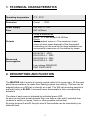
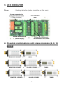
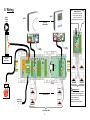
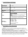
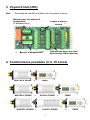
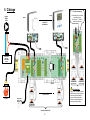
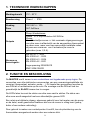
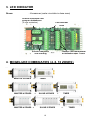
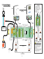
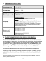
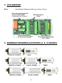
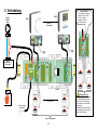
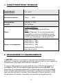
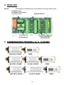
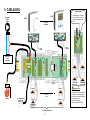
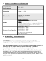
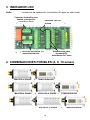
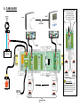
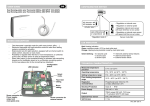
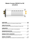
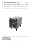
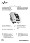
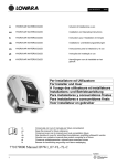
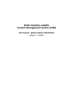
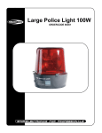
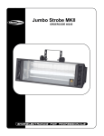
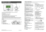
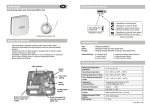
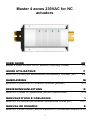
Master 4 zones 230VAC for NC
actuators
USER GUIDE
GB
Master 4 zones 230VAC for NC actuators (Normally Closed)
GUIDE UTILISATEUR
3-5
F
MASTER 4 zones pour électrovannes Normalement Fermées (NC)
HANDLEIDING
6-8
Nl
MASTER 4 zones voor NC actuators (normaal gesloten)
BEDIENUNGSANLEITUNG
9-11
D
MASTER 4 Zonen für Stellantriebe (stromlos geschlossen)
MANUALE D'USO E CABLAGGIO
MASTER 4 zones per elettrovalvole Normalmente Chiuse (NC)
MANUAL DE USUARIO
12-14
I
15-17
E
MASTER 4 zonas 230VAC para actuadores NC (normalmente cerrados)18-20
1
2
1. TECHNICAL CHARACTERISTICS
Operating temperature
0°C - 50°C
Protection
Class I - IP20
Power supply
Fuse
230 VAC +/- 10%
5AT 5x20mm
Outputs
Pump & accessories:
Relay => 2 free contact 8A 250Vac
Zones:
4 independent zones => The maximum output
power of each zones depends of the thermostat
connecting on this zone but for easy installation we
recommend a maximum of 4 actuators by zones.
Norms and
homologation:
EN 60730-1 : 2003
EN 61000-6-1 : 2002
EN 61000-6-3 : 2004
EN 61000-4-2 : 2001
Low voltage 2006/95/CE
EMC 2004/108/CE
2. DESCRIPTION AND FUNCTION
The MASTER with 4 zones is a wiring module with built in pump logic. All the main
electrical connections for water floor heating system are existing. This box can be
adapted either on a DIN rail or directly on a wall. The DIN rail mounting permits to
add with facility a SLAVE. It connects room thermostats to their corresponding
actuators.
The state of each zone is indicated by individual green LED.
As soon as we have a heat demand from one zone a relay with 2 potential-free
contacts is switch on (pump, boiler or other possible connection).
By using terminal A and B, the pilot wire of thermostats can be controlled by an
external clock.
3
3. LED INDICATOR
Green:
- Heating indication (water circulation on this zone)
Screw connector for
pump and accessories
(2 free contacts)
LED indicator
zone
Screw connector for
power supply
Supply for thermostat
and actuators for 1 zone
4. Possible combinations with slave modules (4, 8, 10
zones)
MASTER 4 ZONES
MASTER 4 ZONES
+
+
MASTER 4 ZONES +
TIMER
SLAVE 4 ZONES
+
SLAVE 6 ZONES
4
TIMER
+
TIMER
5. Wiring
Bridge function
1 thermostat for several
zones control. Only the
points “1” need to be
bridged between the zones.
WFHT
Pump
230Vac
50Hz
WFHT
Up to 12
thermostats
N PE L
4 4
2 1
A/B
4 4 2
1 A/B
sensor
N PE L
External Power
Supply
230Vac 50Hz
4 actuators
max per zone
SLAVE
230NCx
230NCx
Up to 12 zones
BOILER
Power Supply
230Vac 50Hz
230NCx
230NCx
4 actuators
max per zone
24 actuators Max
5
4 actuators
max per zone
Important note
In this way, the maximum number
of actuators (zones bridged) will
be done by the current capacity of
the thermostat used.
Check the thermostat
characteristics before bridge.
1. Caractéristiques techniques
Température de
fonctionnement
0°C - 50°C
Protection électrique
Class I - IP20
Alimentation
Fusible
230 VAC +/- 10%
5AT 5x20mm
Sorties
Pompe et accessoires:
Relais => 2 contacts secs de tout potentiel 8A 250Vac
Zones:
4 zones indépendantes => Le courant maximum
admissible dans une zone est donné par le thermostat
connecté sur cette zone. Le courant maxi pour toutes
les zones (thermostat + vannes) est de 2.5A.
Normes et
homologation:
EN 60730-1 : 2003
EN 61000-6-1 : 2002
EN 61000-6-3 : 2004
EN 61000-4-2 : 2001
Basse tension 2006/95/CE
CEM 2004/108/CE
2. Description et Fonctionnement
Le MASTER 4 zones est une boîte de connexions pour plancher hydraulique. La
connexion de tous les éléments électriques d’une installation de chauffage est prévue
(thermostat, électrovannes, circulateur…).
La fixation mécanique de la boîte peut être adaptée soit sur un DIN Rail soit sur un mur.
Le montage sur le DIN RAIL permet d’ajouter facilement un SLAVE. Les leds
permettent de visualiser rapidement l’état de chaque zone. Un relais à double sortie,
utilisé généralement pour la commande du circulateur et de la chaudière est enclenché
dès qu’une des zones en demande. 2 lignes de contrôle A et B sont disponibles. Elles
vous permettront via la centrale de programmation de piloter les thermostats.
6
3. Voyant d’état (LED)
Vert:
- Demande de chauffe (circulation de l’eau dans la zone)
Bornier pour circulateur et
accessoires
(2 contacts secs)
Voyant d’état de
la zone
Connexions pour une zone
(thermostat, électrovannes)
Bornier d’alimentation
4. Combinaisons possibles (4, 8, 10 zones)
MASTER 4 ZONES
MASTER 4 ZONES
+
+
MASTER 4 ZONES +
TIMER
SLAVE 4 ZONES
+
SLAVE 6 ZONES
7
TIMER
+
TIMER
5. Câblage
Fonction du pontage
1 thermostat pour le contrôle
de plusieurs zones
Seul le point “1” doit être
ponté entre les zones
WFHT
Pompe
230Vac
50Hz
WFHT
Jusqu’à 12
thermostats
N PE L
4 4
2 1
A/B
4 4 2
1 A/B
sensor
N PE L
Alimentation
extérieure
230Vac 50Hz
Supply
230Vac 50Hz
4 electrovannes
max par zone
SLAVE
230NCx
230NCx
Jusqu’à 12 zones
Chaudière
Alimentation
230Vac 50Hz
230NCx
230NCx
4 electrovannes
max par zone
24 electrovannes Max
8
4 electrovannes
max par zone
Note importante
Dans ce cas, le nombre maximal
d’électrovannes (zones pontées)
est donné par la capacité de
courant du thermostat utilisé.
Vérifier les caractéristiques du
thermostat avant pontage
1. TECHNISCHE EIGENSCHAPPEN
Werkingsbereik
0°C - 50°C
Bescherming
Class I - IP20
Voeding
Fuse
230 VAC +/- 10%
5AT 5x20mm
Outputs
Pomp & toebehoren:
Relais => 2 vrije contacten 8A 250Vac
Zones:
4 onafhankelijke zones => Het maximale uitgangsvermogen
van elke zone is afhankelijk van de aangesloten thermostaat
op deze zone, maar voor een eenvoudige installatie raden
wij aan een maximum van 4 actuators per zone te
gebruiken (max. 2,5 A).
Normen en
homologatie:
EN 60730-1 : 2003
EN 61000-6-1 : 2002
EN 61000-6-3 : 2004
EN 61000-4-2 : 2001
Lage spanning 2006/95/CE
EMC 2004/108/CE
2. FUNCTIE EN BESCHRIJVING
De MASTER met 4 zones is een contactdoos met ingebouwde pomp logica. De
connecties voor alle elektrische componenten van een verwarmingsinstallatie zijn
voorzien (thermostaat, actuator, pomp,…). Dit toestel kan gemonteerd worden op
een DIN rail of rechtstreeks op de muur. De montage met de DIN rail laat toe
gemakkelijk de SLAVE hieraan toe te voegen.
De LED's laten toe snel de status van elke zone vast te stellen. De status van
elke zone wordt aangeduid met een afzonderlijke groene LED.
Een relais met dubbele uitgang, algemeen gebruikt voor het regelen van de pomp
en de ketel, wordt geactiveerd wanneer één van de zones in vraag komt (pomp,
boiler of een andere verbinding).
Door gebruik te maken van contactpunten A and B, kan de pilootsturing van de
thermostaten aangestuurd worden door een externe klok.
9
3. LED INDICATOR
Groen:
- Verwarmen (water circulatie in deze zone)
Schroef connectie voor
pomp en toebehoren
(2 vrije contacten)
LED indicator
zone
Schroef connectie
voor voeding
Toevoer voor thermostaat
en actuators voor 1 zone
4. MOGELIJKE COMBINATIES (4, 8, 10 ZONES)
MASTER 4 ZONES
+
MASTER 4 ZONES
MASTER 4 ZONES +
+
TIMER
SLAVE 4 ZONES
SLAVE 6 ZONES
10
+
TIMER
+
TIMER
5. Aansluitingen
Overbrugging
1 thermostaat bedient
meerdere zones. Enkel
contactpunt “1” dient met
een overbrugging tussen de
zones verbonden te
worden.
WFHT
Pomp
230Vac
50Hz
WFHT
tot 12
thermostaten
N PE L
4 4
2 1
A/B
4 4 2
1 A/B
sensor
N PE L
Externe voeding
230Vac 50Hz
4 actuators
max per zone
SLAVE
230NCx
230NCx
tot 12 zones
Vrijgavecontact
Voeding
230Vac 50Hz
230NCx
230NCx
4 actuators
max per zone
24 actuators Max
11
4 actuators
max per zone
Belangrijke opmerking
In dit geval zal het maximum
aantal actuators (overbrugde
zones) bepaald worden door de
capaciteit van de gebruikte
thermostaat.
Controleer daarom de kenmerken
van de thermostaat vooraleer de
overbrugging te maken.
1. TECHNISCHE DATEN
Raumtemperatur
0 °C – 50 °C
Schutzklasse
Klasse I - IP20
Betriebsspannung
Sicherung
230 V AC +/- 10%
5 AT 5x20mm
Ausgänge
Pumpe & Zubehör:
Relais => 2 freie Kontakte 8 A 250 V AC
Zonen:
4 unabhängige Zonen => Die maximale Leistung jeder
einzelnen Zone hängt von dem an diese Zone
angeschlossenen Thermostat ab. Bei einer einfachen
Anlage empfehlen wir den Anschluss von maximal 4
Stellantrieben pro Zone.
Normen und
Zulassungen:
EN 60730-1 : 2003
EN 61000-6-1 : 2002
EN 61000-6-3 : 2004
EN 61000-4-2 : 2001
Niederspannung 2006/95/CE
EMC 2004/108/CE
2. FUNKTIONSWEISE UND BESCHREIBUNG
Bei dem Modell MASTER mit 4 Zonen handelt es sich um einen Regelverteiler
mit eingebauter Pumpenlogik. Er verfügt über alle elektrischen Hauptanschlüsse
für eine Wasser-Fußbodenheizung. Der Verteiler kann entweder auf eine DINSchiene oder direkt an der Wand montiert werden. Bei Montage auf einer DINSchiene kann ein SLAVE problemlos hinzugefügt werden. Er ermöglicht die
Verbindung von Raumthermostaten mit den entsprechenden Stellantrieben.
Der Zustand jeder einzelnen Zone wird durch individuelle LEDs angezeigt.
Sobald von einer Zone ein Heizbedarf gemeldet wird, wird ein Relais mit zwei
potentialfreien Kontakten (Pumpe, Boiler bzw. andere Anschlussmöglichkeit)
aktiviert.
Die Thermostate können mithilfe der Steuerleitungen A und B über eine Uhr
extern gesteuert werden.
12
3. LED-ANZEIGE
Grün:
- Heizbetrieb (Wasserumwälzung in dieser Zone)
Schraubverbindungen für
Pumpe und Zubehör
(2 potentialfreie Kontakte)
LED-Anzeige für
Zone
Schraubverbindung
für Stromversorgung
Anschlüsse für
Thermostat Stellantriebe
für 1 Zone
4. KOMBINATIONSMÖGLICHKEITEN (4, 8, 10 ZONEN)
MASTER 4 ZONES
MASTER 4 ZONES
+
+
MASTER 4 ZONES +
TIMER
SLAVE 4 ZONES
SLAVE 6 ZONES
13
+
TIMER
+
TIMER
5. Verkabelung
Brückenfunktion
1 Thermostat zur Regelung
mehrerer Zonen. Nur die
Punkte „1“ müssen
zwischen den Zonen
überbrückt werden.
WFHT
Pumpe
230Vac
50Hz
WFHT
Bis zu 12
Thermostate
N PE L
4 4
2 1
A/B
4 4 2
1 A/B
sensor
N PE L
Externe
Stromversorgung
230VAC 50Hz
max. 4
Stellantriebe
SLAVE
230NCx
230NCx
Up to 12 zones
BOILER
Stromversorgung
230Vac 50Hz
230NCx
230NCx
max. 4
Stellantriebe
pro Zone
max. 24 Stellantriebe
14
max. 4
Stellantriebe
Wichtiger Hinweis!
Somit wird die maximale Anzahl
an Stellantrieben (überbrückte
Zone) durch die Stromleistung
des verwendeten Thermostats
vorgegeben.
Überprüfen Sie die technischen
Eigenschaften des Thermostats,
bevor Sie überbrücken.
1. CARATTERISTICHE TECNICHE
Temperatura di
funzionamento
0°C - 50°C
Protezione elettrica
Class I - IP20
Alimentazione
Fusibile
230 VAC +/- 10%
5AT 5x20mm
Uscite
Pompa e accessori:
Relè => 2 contatti puliti da 8A 250Vac
Zone:
4 zone indipendenti => La corrente massima
ammissibile in una zona è data dal termostato
collegato a tale zona. La corrente massima per
tutte le zone (termostato + valvole) è di 2.5A.
Norme e omologazione:
EN 60730-1 : 2003
EN 61000-6-1 : 2002
EN 61000-6-3 : 2004
EN 61000-4-2 : 2001
Bassa tensione 2006/95/CE
EMC 2004/108/CE
2. DESCRIZIONE E FUNZIONAMENTO
La MASTER 4 zone è una scatola di connettori per riscaldamento idraulico a
pavimento. Consente la connessione di tutti gli elementi elettrici di un impianto di
riscaldamento (termostato, elettrovalvole, circolatore…).
Il fissaggio della scatola può essere effettuato sia su DIN Rail sia a parete. Il
montaggio su DIN RAIL permette di aggiungere facilmente un SLAVE. I led
permettono di visualizzare rapidamente lo stato di ogni zona. Un relè a doppia
uscita, utilizzato generalmente per comandare il circolatore e la caldaia, scatta
ogni volta che una zona lo richiede. Sono disponibili 2 linee di controllo, A e B,
che permettono di pilotare i termostati via la centrale di programmazione.
15
3. SPIA LED
Verde:
- Richiesta di riscaldamento (circolazione d'acqua nella zona)
Connettore per
circolatore e accessori
(2 contatti puliti)
Spia led di zona
Connessioni per una
zona (termostato,
elettrovalvole)
Connettore di
alimentazione
4. COMBINAZIONI POSSIBILI (4, 8, 10 ZONE)
MASTER 4 ZONES
MASTER 4 ZONES
+
+
MASTER 4 ZONES +
TIMER
SLAVE 4 ZONES
SLAVE 6 ZONES
16
+
TIMER
+
TIMER
5. CABLAGGIO
Funzione ponte
1 termostato per il controllo
di più zone. Solo i punti “1”
vanno messi in ponte fra le
zone.
WFHT
Circolatore
230Vac
50Hz
WFHT
Fino a 12
termostati
N PE L
4 4
2 1
A/B
4 4 2
1 A/B
sensor
N PE L
Alimentazione
esterna
230Vac 50Hz
4 elettovalvole
max per zona
SLAVE
230NCx
230NCx
Fino a 12
zones
BOILER
ALIMENTAZIONE
230Vac 50Hz
230NCx
230NCx
4 elettovalvole
max per zona
pro Zone
24 elettrovalvole Max
17
4 elettovalvole
max per zona
Important note
In this way, the maximum number
of actuators (zones bridged) will
be done by the current capacity of
the thermostat used.
Check the thermostat
characteristics before bridge.
1. CARACTERÍSTICAS TÉCNICAS
Temperatura de
funcionamiento
0°C - 50°C
Protección
Clase I - IP20
Alimentación
230 VAC +/- 10% 50Hz
5AT 5x20mm
Salidas
Normas y homologación:
Bomba y accesorios:
Relé => 2 contactos libres 8A 250Vac
Zonas:
4 zonas independientes => la potencia máxima de
salida de cada zona depende del termostato
conectado en la misma.
EN 60730-1 : 2003
EN 61000-6-1 : 2002
EN 61000-6-3 : 2004
EN 61000-4-2 : 2001
De baja tensión 2006/95/CE
EMC 2004/108/CE
2. FUNCIÓN y DESCRIPCIÓN
El MASTER 4 zonas es un módulo de conexión con lógica de bomba
incorporada. Todas las conexiones eléctricas principales para el sistema de
calefacción por suelo radiante están realizadas de antemano.
Esta caja puede adaptarse a un raíl DIN o montarse directamente en la pared. (El
montaje en raíl DIN permite añadir un módulo ESCLAVO). Conecta los
termostatos de ambiente con sus actuadores correspondientes.
El estado de las zonas queda indicado mediante LEDs individuales. Usando los
terminales A y B, el hilo piloto de los termostatos puede ser controlado por un
TEMPORIZADOR externo. Tan pronto tenemos una demanda de calor en una
zona, se activa un relé con 2 contactos libres de potencial (bomba, caldera u otra
posible conexión).
18
3. INDICADOR LED
Verde:
- Indicación de calefacción (circulación de agua en esta zona)
Conector de tornillo para
bomba y accesorios
2 contactos libres
Indicador LED de
la zona
Alimentación para
termostato y
actuadores de 1 zona
Conector de tornillo
para alimentación
4. COMBINACIONES POSIBLES (4, 8, 10 zonas)
MASTER 4 ZONAS
MASTER 4 ZONAS
+
+
MASTER 4 ZONAS +
TEMPORIZADOR
ESCLAVO 4 ZONES +
ESCLAVO 6 ZONES
19
TEMPORIZADOR
+
TEMPORIZADOR
5. CABLEADO
Puente de la función
Un termostato para el
control de varias zonas.
Sólo los puntos "1" deben
ser un puente entre las
zonas.
WFHT
Bomba
230Vac
50Hz
WFHT
Hasta 12
termostatos
N PE L
4 4
2 1
A/B
4 4 2
1 A/B
sensor
N PE L
Alimentación
230Vac 50Hz
4 actuators
max per zone
SLAVE
230NCx
230NCx
Up to 12 zones
BOILER
Alimentación
230Vac 50Hz
230NCx
230NCx
4 actuators
max per zone
24 actuators Max
20
4 actuators
max per zone
Nota importante
De esta manera, el máximo número
de actuadores (zonas de puente) se
llevará a cabo por la actual
capacidad de utilizar el termostato.
Compruebe las características del
termostato antes del puente.
21
22
23
www.wattsindustries.com
PPLIMP02011
Ba
24