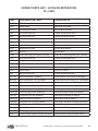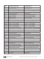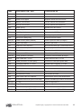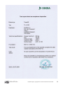
1
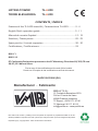
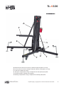
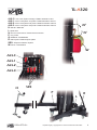
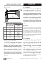
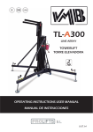
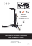
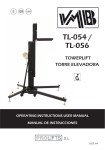
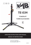
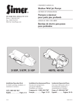
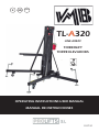
E
GB
USA
TL-A320
LINE ARRAY
TOWERLIFT
TORRE ELEVADORA
OPERATING INSTRUCTIONS USER MANUAL
MANUAL DE INSTRUCCIONES
V.07.14
LIFTING TOWER
TORRE ELEVADORA
TL-A320
TL-A320
CONTENTS / ÍNDICE
Features of the TL-A320 towerlift / Características TL-A320.............. 3 - 4
English Quick operation guide.................................................................... 5 - 11
Manual de usuario Español.......................................................................... 12 - 19
Sketches / Planos piezas................................................................................ 20 - 29
Spare part list / Lista de repuestos.............................................................. 30 - 32
Certifications / Certificaciones......................................................................33
BGV-C1
BGG-912
EC Conformity Declaration pursuant to the EC Machinery Directives 89/392/CE and
98/37/CE: Manual lifters
Find a copy of the certifications at the end of this booklet.
Puede ver una copia de las certificaciones al final del manual.
MADE IN SPAIN (EU)
Manufacturer - Fabricante
PRO LIFTS S.L.
C/ Ciudad de Barcelona Nº19
Pol.Ind. Fuente del Jarro
46988 Paterna (Valencia)
Tlf Export: +34 96 171 81 86
Tlf Nacional: 96 171 81 83
[email protected] - www.prolifts.es
Este manual de usuario y catálogo anexo de piezas de repuesto es propiedad de PRO LIFTS S.L.
Queda prohibida su reproducción total o parcial por cualquier medio que la tecnología actual permita.
Deposito legal y copyright 2014. Todos los derechos reservados.
TL-A320
A
F
E
S
V
T
V
T
A: Reinforcement struts for line array / Refuerzo especial para Line Array
E: Anchor points for struts / Anclaje del tirante refuerzo frontal para Line Array
F: Load forks / Brazos de carga
S: Transport compartment for legs / Alojamiento de transporte para patas
T: Transport wheels / Ruedas de transporte
V: Working compartment for legs / Alojamiento de trabajo para patas
PRO LIFTS S.L.
Depósito legal y copyright 2014. Todos los derechos reservados.
3
TL-A320
ALS-C: Auto Lock System carriage / Gatillo automático carro
ALS-1: Auto Lock System 1st profile / Gatillo automático tramo 1
ALS-2: Auto Lock System 2nd profile / Gatillo automático tramo 2
ALS-3: Auto Lock System 3rd profile / Gatillo automático tramo 3
H: Handle / Manivela
L: Spirit level
N: Force on hand crank / Fuerza sobre manivela
P: Leg / Pata
Q: Stabilizer / Estabilizador
R: Catch pawl / Gatillo bloqueo patas
SRS: Sequence Retainer System
W: Winch / Cabrestante
N2
N1
W
ALS-C
ALS-1
ALS-2
ALS-3
H
SRS
P
R
L
Q
PRO LIFTS S.L.
Depósito legal y copyright 2014. Todos los derechos reservados.
4
Quick operation guide
CONTENTS
ENGLISH
2. TECHNICAL INFORMATION
1. Introduction.
2.1 - TL-A320 Towerlift.
2. Technical information.
3. Safety precautions.
2.2 - Designed to lift audio systems, such
4. Operation.
as PA systems or Line Array, up to diffe-
5. Maintenance.
rent heights.
6. Guarantee.
2.3 - Maximum load : 320 kg (705 lb).
2.4 - Minimum load: 25 Kg (55 lb).
1. INTRODUCTION
2.5 - Security :
Dear customer, in order to ensure a safe
and reliable operation of the TL-A320
towerlift please follow the instructions in
this booklet carefully. Before operating the
lift, read the instructions completely and
please note the technical information contained within this manual.
All VMB products undergo very rigorous
ALS (Automatic Lock System).
2.6 - Maximum height : 6.00 m (19.7’).
2.7 - Folded height : 1.98 m (6.5’).
2.8 - Work surface :
2.25 x 2.15 m (7.4’ x 7.1’).
2.9 - Unit weight : 184 Kg (405 lb).
testing, under strict conditions and they
2.10. - Load support:
are monitored continuously during the ma-
Long forks (74.5 cm).
nufacturing process.
2.11 - Construction material : 6082-T6
In order to guarantee the lifts function and
alluminium for the main body, comprised
safety, only original parts from the manu-
of 4 profiles and a lifting carriage. Base
facturer must be used. If any parts other
and legs are made of steel profile accor-
than those of the manufacturer are used,
ding to DIN 2394. Catches and pulleys of
or the product is modified in any way, the
ST-37 steel.
user forfeits all warranty rights to claim.
duct specifications without prior notice.
2.12 - Winch: 1200 Kg. maximum load
with automatic brake. Certification CE and
GS TÜV.
The model type, production year and se-
2.13 - Cable : Steel DIN 3060. Quality 180
rial number must be quoted in any queries
Kg/mm2 twist resistant.
or orders for spare parts.
Cable diameter: 6 mm.
VMB reserves the right to modify the pro-
PRO LIFTS S.L.
Depósito legal y copyright 2014. Todos los derechos reservados.
5
Quick operation guide
ENGLISH
2.14 - Adjustable stabilizing feet with rub-
can be supplied with natural aluminium
ber non-slip supports.
finish or black (version B).
2.15 - Safety catches to anchor the legs.
2.17 - Spirit level to adjust the tower ver-
2.16 - Antirust protection, primed paint
with cured polyester dust cover. The tower
tically.
2.18 - Swivel wheels to transport the lift
when folded.
3. SAFETY PRECAUTIONS.
3.1 - The TL-A320 is a machine designed to elevate
loads upwards in a vertical direction, It should NEVER
be used as a platform to elevate people.
3.2 - Only place the lift on hard, flat surfaces always
checking that it is in a vertical position by using the bubble level indicator (L) found on the base. Adjust the leg
stabilizers (Q) by turning the handles (H) to level if necessary. NEVER use wedges or other foreign objects to
balance the lift.
3.3 - The maximum load indicated on the characteristics
label and the instructions manual should not be exceeded.
3.4 - This lift should NEVER be used to elevate a load
that has not been properly checked. It is necessary to
verify that the load is correctly supported and centred
on the appropriate lift support so that the weight of the
load will only elevate in a vertical direction.
PRO LIFTS S.L.
Depósito legal y copyright 2014. Todos los derechos reservados.
6
Quick operation guide
ENGLISH
3.5 - Check that the legs (P) are placed and set-up correctly with their safety pins (R) inserted and locked.
3.6 - NEVER use the lift on a vehicle or any other mobile
surface.
3.7 - If there is a possibility of strong winds or gusts,
place the lift on the ground firmly and secure it with the
use of straps. NEVER attach a strap to a vehicle or any
other object that can possibly be moved.
3.8 - NEVER move the lift whilst it is carrying a load. It
is not advisable to carry out any type of horizontal movement even small positional adjustments.
3.9 - NEVER allow any team member below the load or
anybody else in the lifts operating zone.
3.10 - Take care with all obstacles above the lift and
its extension zone such as cornices, balconies, and
luminous signboards. It is very important to avoid the
presence of all types of cables below the extended lift.
PRO LIFTS S.L.
Depósito legal y copyright 2014. Todos los derechos reservados.
7
Quick operation guide
ENGLISH
3.11 - Do not use stepladders on the lift or use it as a
support for them.
3.12 - Before using the lift, check the condition of the
cable. The cable should not have broken threads or
show any signs of crushed/flattened areas. NEVER use
faulty cables, always change them if there is any doubt.
Only use VMB steel cables; reference: DIN 3060.
Quality: 180KG/mm and torsion resistant.
3.13 - All sections must be lowered first, and the legs
placed in its transport position, before transportation.
3.14 - Do not grease or lubricate the winch’s braking
mechanism. The brake disks have been greased with
a special heat and pressure resistant solution. Other
products should not be used to avoid negative effects
regarding the braking mechanism.
3.15 - The minimum load to avoid problems regarding
the braking mechanism is 25Kg. Without this load the
brake will not work.
3.16 - NEVER take apart the crank of the winch when
the lift is carrying a load or extended.
PRO LIFTS S.L.
Depósito legal y copyright 2014. Todos los derechos reservados.
8
Quick operation guide
ENGLISH
3.17 - Only original replacement parts should be used.
ORIGINAL
need, use so that the weight of the load
4. USER INSTRUCTIONS.
will only be elevated in a vertical direction.
4.1 - Place the lift on a firm, flat surface
The minimum load is 25 Kg.
in the area it is to be used with the help of
4.6 - How to place the load: Always load
the transport wheels (T).
as close to the tower as possible.
4.2 - Remove the legs (P) from their trans-
The maximum load diminishes according
port compartment (S) and fully insert them
to the distance from the body of the tower
into their working positions (V) checking
as illustrated in the diagram 4.6.1, which
that they are fixed by the pins (R). Remo-
shows the load on the gravity centre with
ve the reinforcement struts (A) as well and
distances to the lifting carriage at a maxi-
place them in their anchor points (E), fix
mum lifting. Use a VMB adaptor if neces-
them with their corresponding pins and
sary.
clips.
CAUTION
4.3 - Check that the lift is in vertical posi-
When two towers are used to elevate a
tion using the spirit level (L) at the base of
truss bridge, or many towers to elevate a
the tower, adjust the stabilizer (Q), turning
structure of any type, it is almost impos-
the handle (H) if necesary.
sible that two or more people co-ordinate
4.4 - Release the forks (F) and place them
the winches elevating or lowering the
in its working horizontal position ready to
loads, at exactly the same pace. At a cer-
take the load on them. Insert the pins to
tain point each tower will be extended to
block the forks.
different height. For this reason it is necessary that the structure does not stretch
4.5 - DO NOT OVERLOAD THE LIFT.
MAXIMUM LOAD IS 320 kg (705 lb)
With a rigid fixation and if the level diffe-
The lift should NEVER be overloaded.
Safety at work is the most important issue. Place the load onto the lift using an
adequate VMB support according to the
PRO LIFTS S.L.
and allows for these differences.
rence is significant, the force generated
from the handle of the winch will deform
the structure and apply a lateral force to
the lifts causing them to break and block.
Depósito legal y copyright 2014. Todos los derechos reservados.
9
Quick operation guide
ENGLISH
4.7 - Elevation:
Diagram 4.6.1
Turn the winch crank clockwise (N1) to lift
the carriage and profiles. The ALS system enable the lift to rise and automatically block the carriage and profiles whilst
A
rising ensuring that it will never fall. This
B
enables the cable to be without any force
C
and means it is only used for the elevation
D
E
and descent of the lift. The SRS (Sequence-Retainer-System) will also ensure that
the profiles rise in sequence, one after the
other.
Distance from the
load’s center to the
axel of the tower
Maximum load
A
50 cm
(1.64’)
320 kg
(705 lb)
The tower can be left in any intermediate
B
55 cm
(1.80’)
291 kg
(641 lb)
the handle of the winch and gently turn it
C
60 cm
(1.97’)
267 kg
(589 lb)
the last profile risen. The ALS lock will
D
65 cm
(2.13’)
246 kg
(542 lb)
E
70 cm
(2.30’)
200 kg
(441 lb)
TL-A320
4.8 - Hold:
position if it is necessary. Just stop turning
in an anticlockwise direction (N2) to block
take the pressure of the load and release
strain applied on the cable.
4.9 - Lowering:
To bring the lift down you need to first
Security system ALS / ILS
turn the winch handle slightly clockwise
The TL-A320 incorporates the patented
(N1) and at the same time pull the red
security system ALS (Automatic Lock
ALS lock (ALS-1) out. This releases the
Security). This VMB red trigger system
blocking systems. Then turn the handle
automatically blocks the tower in the po-
anti-clockwise (N2), whilst maintaining the
sition it is left in. Each section of lift has
ALS lock pulled out until the profile has
an ALS that blocks the section in the un-
been completely lowered. All red ALS
likely event of the cable breaking. For a
locks (ALS-2, ALS-3 & ALS-C) should be
more complete security the lifting carriage
pulled out one by one whilst the handle is
incorporates the ILS system (Inertial Lock
turned anti-clockwise (N2) and the profiles
Security)
are brought down, one by one.
PRO LIFTS S.L.
Depósito legal y copyright 2014. Todos los derechos reservados.
10
Quick operation guide
ENGLISH
If you release your finger from the ALS
spiral of the crank, and the sections.
lock it will automatically block. In this
5.3 - All lifts should undergo an annual
case, repeat the first operation by turning
technical inspection carried out by an
slightly clockwise (N1) and then anti-cloc-
authorized VMB dealer to check the cer-
2
kwise (N ) whilst always pulling the red
tifications and general condition of all the
ALS lock out. It is necessary to completely
lift’s elements and security systems invol-
lower each profile before starting to lower
ved in the lift’s use.
the next. DO NOT pull another red ALS
lock without having completely lowered
5.4 - Only use original spare parts to gua-
the previous profile.
rantee a continued security level. The
user loses all rights to warranty if any spa-
4.10 - Transport:
re parts other than originals are used or
For the transport of the tower is necessary
carries out any modification or alteration
to fold the machine lowering every profile
to the towerlift.
completely. Once the towerlift is completely folded, place the legs and the struts
5.5 - To request a spare part please in-
(A) in their transport compartment (S) lo-
dicate the corresponding code which can
cated at the legs, then the lift will be ready
be found in this manual together with the
to be transported.
lift’s serial number and year of manufacture.
5. MAINTENANCE.
6. GUARANTEE.
5.1 - Regularly check the state of the cable. If the cable has broken threads, or if
The warranty period for this lift is 2 years
it shows any signs of crushed/flattened
from the date of purchase.
areas, it should be changed and replaced
immediately with a new one. Do not use
PRO LIFTS S.L. promises, that from the
the lift if the cables are in bad condition.
date of purchase and during the warranty
Only use VMB steel cables reference: DIN
period to resolve any faults that may oc-
3060 torsion resistant.
cur, produced through defect material or
5.2 - The lift is supplied from the factory
completely greased. However, it is recommended to periodically grease according
to use, the gearing, the axis bearings, the
PRO LIFTS S.L.
fabrication. Damage caused by improper
use, product modification, third party manipulation or accidental fire are not covered by this warranty.
Depósito legal y copyright 2014. Todos los derechos reservados.
11
Manual de usuario
ESPAÑOL
CONTENIDO
2. INFORMACIÓN TÉCNICA
1. Introducción.
2.1 - Torre elevadora TL-A320.
2. Información técnica.
3. Precauciones de seguridad.
2.2 - Diseñada para levantar sistemas de
4. Instrucciones de uso.
audio, como sistemas de Line Array o PA,
5. Mantenimiento.
en sentido vertical a diferentes alturas.
6. Garantía.
2.3 - Carga máxima: 320 kg (705 lb).
1. INTRODUCCIÓN
2.4 - Carga mínima: 25 Kg (55 lb).
Estimado cliente: Con el fin de garantizar
2.5 - Seguridad: ALS (Sistema de gatillo
un funcionamiento seguro y fiable de la
automático de seguridad).
torre elevadora TL-A320 por favor, siga
2.6 - Altura máxima: 6 m (19.7’).
cuidadosamente las instrucciones de este
manual. Antes de manipular la torre ele-
2.7 - Altura plegada: 1,98 m (6.5’).
vadora, lea las instrucciones completas
2.8 - Área de la base:
y tenga en cuenta la información técni-
2.25 x 2.15 m (7.4’ x 7.1’).
ca contenida en este manual. Todos los
productos de VMB se someten a pruebas
2.9 - Peso de la torre: 184 kg (405 lb).
muy rigurosas, en condiciones estrictas y
2.10 - Soporte de carga:
son monitorizados continuamente duran-
Brazos de carga largos (74.5cm).
te el proceso de fabricación. Con el fin de
garantizar el correcto funcionamiento y
seguridad de los elevadores, sólo deben
ser utilizadas piezas originales del fabricante. Si se utilizan piezas que no sean
las originales del fabricante, o el producto
se modifica de alguna manera, el usuario
2.11 - Material de construcción: Cuerpo
principal de cuatro tramos más carro elevador en perfil de aluminio extrusionado
6082-T6. Base, patas y soportes varios,
en perfileria de acero según DIN 2394.
Gatillos de seguridad y poleas acanaladas en acero ST-37.
pierde todos los derechos de garantía.
VMB se reserva el derecho de modificar
2.12 - Cabestrante: 1200 kg de carga
las especificaciones y las piezas del pro-
máxima con freno automático de retención
ducto sin previo aviso. El tipo de modelo,
de la carga. Certificación CE y GS TÜV.
año de producción y el número de serie
2.13 - Cable: Acero DIN 3060. Calidad de
deben ser citadas en cualquier consulta o
resistencia a la torsión 180 kg/mm2.
pedido de piezas de recambio.
Diámetro del cable: 6 mm.
PRO LIFTS S.L.
Depósito legal y copyright 2014. Todos los derechos reservados.
12
Manual de usuario
ESPAÑOL
2.14 - Patas estabilizadoras ajustables
do natural de aluminio o negro (versión
con soportes de goma antideslizante.
B).
2.15 - Gatillos de seguirdad para anclar
2.17 - Nivel de burbuja para ajustar la verticalidad de la torre.
las patas.
2.16 - Protección anti-óxido, imprimación
con pintura de polvo poliester al horno. La
2.18 - Ruedas direccionales para el transporte de la torre cuando este plegada.
torre puede ser suministrada con acaba-
3. PRECAUCIONES DE SEGURIDAD
3.1 - La torre elevadora TL-A320 es una máquna diseñada
para la elevación de cargas en dirección vertical. NUNCA
se debe utilizar como plataforma eleavadora de personas.
3.2 - Colocar el elevador sólo en superficies firmes y planas,
verificando que está en posición vertical, utilizando el indicador de nivel de burbuja (L) que se encuentra en la base.
Ajuste los estabilizadores (Q) girando las manivelas (H)
hasta nivelar, si es necesario. Nunca utilice cuñas u otros
objetos extraños para equilibrar el elevador.
3.3 - La carga máxima indicada en las características técnicas mostradas en la etiqueta de la torre o en este manual
NO deben ser excedidas.
3.4 - Este elevador NUNCA debe utilizarse para elevar una
carga que no ha sido correctamente revisada. Es necesario
verificar que la carga está correctamente apoyada y centrada en el soporte de elevación apropiado para que el peso de
la carga sólo actúe en una dirección vertical.
PRO LIFTS S.L.
Depósito legal y copyright 2014. Todos los derechos reservados.
13
Manual de usuario
ESPAÑOL
3.5 - Comprobar que las patas (P) estén situadas correctamente, y fijadas con los gatillos de seguridad (R) los cuales
deben estar introducidos y bloqueados.
3.6 - NUNCA use el elevador sobre un vehículo o cualquier
superficie móvil.
3.7 - Si existe la posibilidad de vientos fuertes o ráfagas,
coloque el elevador en el suelo con firmeza y fijelo mediante tirantes tensores. Nunca fije un tirante a un vehículo o
cualquier otro objeto que se pueda mover.
3.8 - NUNCA mueva el elevador mientras esté cargado. No
es aconsejable llevar a cabo cualquier tipo de movimiento
horizontal, ni tan sólo pequeños ajustes de posición.
3.9 - NUNCA permita que ningún miembro del equipo o
cualquier otra persona se sitúe debajo de la carga en la
zona de operación de las torres elevadoras.
3.10 - Tenga cuidado con todos los obstáculos por encima
de la elevación y su zona de extensión, como cornisas,
balcones, letreros luminosos, etc. Es muy importante evitar la presencia de todo tipo de cables por debajo de la
torre extendida.
PRO LIFTS S.L.
Depósito legal y copyright 2014. Todos los derechos reservados.
14
Manual de usuario
ESPAÑOL
3.11 - No usar escaleras encima del elevador ni utilizarlo
como un apoyo para éstas.
3.12 - Antes de utilizar el elevador, compruebe el estado
del cable. El cable no debe contener hilos rotos o mostrar
signos de áreas aplastadas/aplanadas.
NUNCA use cables defectuosos, siempre debe cambiarlos
si hay alguna duda. Utilice solamente cable de acero VMB
referencia: DIN 3060. Calidad: 180kg/mm y resistente a la
torsión.
3.13 - Antes de transportar la torre, todos los tramos deben
ser bajados, y las patas deben extraerse y colocarse en su
posición de transporte.
3.14 - No engrasar ni lubricar el mecanismo de freno del
cabestrante. Los discos de freno vienen engrasados con
una solución especial resistente a la presión y al calor. No
deben utilizarse otros productos, para evitar los efectos
negativos sobre el mecanismo de frenado.
3.15 - La carga mínima para evitar problemas relacionados con el mecanismo de rotura es 25 kg. Sin esta carga
mínima el freno no funcionará.
3.16 - NUNCA desmontar la manivela del cabrestante
cuando el elevador está soportando una carga o extendido.
PRO LIFTS S.L.
Depósito legal y copyright 2014. Todos los derechos reservados.
15
Manual de usuario
ESPAÑOL
3.17 - Sólo deben ser utilizadas piezas de repuesto
originales de VMB PRO LIFTS S.L.
ORIGINAL
La torre elevadora NUNCA debe ser so-
4. INSTRUCCIONES DE USO.
brecargada. La Seguridad en el Trabajo
4.1 - Coloque el elevador sobre una su-
es el elemento más importante. Coloque
perficie firme y plana de la zona de traba-
la carga en el elevador mediante un so-
jo sirviendose de las ruedas direccionales
porte adecuado según la necesidad de
de transporte (T).
modo que el peso de la carga sólo actúe
4.2 - Extraiga las patas (P) de su aloja-
en dirección vertical. La carga mínima
miento para transporte (S) e insertelas
son 25 kg.
totalmente en su posición de trabajo (V),
4.6 - Como colocar la carga:
comprobando que los gatillos de seguridad (R) se insertan y fijan la pata. Extraiga también los tirantes de apoyo especial
(A) y coloquelos en su posición de sujección (E) asegurandolos con su pasador y
clip de seguridad.
Cargue siempre tan cerca de la torre
como pueda. La capacidad de carga de
la torre decrece cuanto más lejos este la
carga separada de la torre, como se ilustra en el esquema (4.6.1) de la siguiente
página. El cual muestra la carga en su
4.3 - Compruebe que la torre esta en
centro de gravedad con distancias al ca-
posición vertical sirviendose del nivel de
rro elevador que sostiene los brazos y a
burbuja (L) situado en el perfil base, si es
máxima altura.
necesario ajuste la vertical de la torre con
los estabilizadores (Q) de las patas, girando las manivelas (H).
PRECAUCIÓN
Cuando se utilizan dos torres para elevar
un puente, descender truss o varias torres
4.4 - Libere los brazos de carga (F) y co-
para elevar una estructura de cualquier
loquelos en posición horizontal e inserte
tipo, es casi imposible que dos o más per-
los pasadores de seguridad con sus clips.
sonas coordinen los cabrestantes exacta-
4.5 - LA CARGA MÁXIMA PARA
TL-A320 ES 320 kg (705 lb).
PRO LIFTS S.L.
mente a la misma velocidad al elevar o
bajar las cargas. En un momento determinado cada torre se elevará a una altura
Depósito legal y copyright 2014. Todos los derechos reservados.
16
Manual de usuario
ESPAÑOL
Sistema de seguridad ALS / ILS
El TL-A320 incorpora el sistema de seguridad patentado ALS (bloqueo automático
de seguridad). Este sistema VMB de gati-
A
B
llo rojo bloquea automáticamente la torre
C
en la posición que se deja. Cada tramo
D
de elevación tiene un ALS que bloquea
E
el tramo en el caso improbable de que el
Esquema 4.6.1
cable se rompa. Para aún más seguridad
el carro también incorpora el sistema ILS
de bloqueo de inercia.
Distancia del
centro de la carga
al eje de la torre
Carga Máxima
TL-A320
Gire la manivela del cabestrante en sen-
A
50 cm
(1.64’)
320 kg
(705 lb)
tramos. El sistema de gatillos ALS le per-
B
55 cm
(1.80’)
291 kg
(641 lb)
mitirá elevar todos los tramos mientras
C
60 cm
(1.97’)
267 kg
(589 lb)
camente, asegurando que la torre nunca
D
65 cm
(2.13’)
246 kg
(542 lb)
fuerza sobre el cable mientras la torre
E
70 cm
(2.30’)
200 kg
(441 lb)
4.7 - Elevación:
tido horario (N1) para elevar el carro y los
que estos se van bloqueando automáticaerá. Esto hace que no actue ninguna
esta parada, lo que significa que solo será
usado para elevar y descender la torre.
El sistema único SRS permite que los
diferente a la de las demás. Por ello, es
perfiles se eleven de forma secuencial u
necesario que la estructura no se esti-
ordenada, uno detrás de otro.
re y permita estas diferencias. Con una
fijación rígida y si la diferencia de nivel es
4.8 - Bloqueo:
importante, la fuerza generada a partir de
La torre puede dejarse en cualquier po-
la manivela del cabrestante deformará la
sición intermedia si se requiere. Una vez
estructura y aplicará una fuerza lateral a
el sistema esta elevado hasta la altura
los elevadores provocando su bloqueo y
deseada tan solo deje de girar la mani-
ruptura.
vela y el freno automático del cabrestan-
PRO LIFTS S.L.
Depósito legal y copyright 2014. Todos los derechos reservados.
17
Manual de usuario
ESPAÑOL
te bloqueará y sujetará la carga, en este
4.7 - Transporte:
momento gire la manivela del cabrestante
Para el transporte de la torre es necesa-
2
en sentido anti-horario (N ) para bloquear
rio bajar completamente todos los tramos.
el último tramo con el gatillo ALS rojo. Los
Una vez la torre haya sido plegada, co-
gatillos tomarán la presión de la carga y
loque las patas y los tirantes de refuerzo
liberará la tensión aplicada al cable.
especial para Line Array en su alojamiento para transporte (S), y la torre ya estará
4.9 - Descenso:
lista para su transporte.
Para descender la torre es necesario,
primero girar la manivela del cabrestante ligeramente en sentido horario (N1)
5. MANTENIMIENTO
para liberar el gatillo ALS rojo (ALS-1), a
continuación girar la manivela en sentido
5.1 - Comprobar periódicamente el esta-
anti-horario (N ) mientras se sigue tirando
do del cable. Si en el cable existen hilos
del gatillo ALS rojo (ALS-1), hasta que el
rotos, o si muestra signos de zonas aplas-
tramo esté completamente bajado. Todos
tadas/aplanadas, debe ser sustituido in-
los gatillos ALS rojos (ALS-2, ALS-3 &
mediatamente por uno nuevo. No use el
ALS-C) deben ser desbloqueados mien-
elevador si los cables están en mal esta-
tras se gira la manivela del cabrestante
do. Utilice solamente cable de acero DIN
2
en sentido anti-horario (N ), repita esta
3060 resistente a la torsión.
operación hasta descender todos los per-
5.2 - La torre elevadora es suministrada
files de uno en uno.
de fábrica completamente engrasada.
Si en el proceso se quita el mano del ALS
Sin embargo, se recomienda un engrase
se bloqueará automáticamente. En este
periódico, según el uso, de las ruedas de
caso, repita la primera operación girando
fricción, los cojinetes de eje, la espiral de
ligeramente la manivela en sentido hora-
la manivela, y los tramos.
rio, desbloquando el ALS y siguiendo en
RECUERDE: NUNCA engrasar ni lubricar
sentido anti-horario, mantener al tiempo
el mecanismo de freno. No es necesario
los ALS rojos desbloqueados. Debe des-
engrasar los discos de freno. Los discos
cender completamente cada tramo antes
de freno vienen engrasados con una so-
de empezar a bajar el siguiente.
lución especial resistente a la presión y al
NUNCA tire de otro ALS rojo sin haber
calor. No deben utilizarse otros productos,
bajado completamente el tramo anterior.
para evitar los efectos negativos sobre el
2
PRO LIFTS S.L.
Depósito legal y copyright 2014. Todos los derechos reservados.
18
Manual de usuario
ESPAÑOL
mecanismo de frenado.
que puedan producirse, debidos a mate-
5.3 - Todos los elevadores se someten a
rial defectuoso o fabricación. Los daños
una inspección técnica anual llevada a
causados por un uso inadecuado, modi-
cabo por un distribuidor autorizado VMB
ficación del producto, la manipulación de
para comprobar las certificaciones y el
terceros o incendio accidental no están
estado general de todos los elementos de
cubiertos por esta garantía.
elevación y sistemas de seguridad que intervienen en el uso del elevador.
5.4 - Utilice únicamente piezas de repuesto originales para garantizar el nivel de
seguridad de forma continuada. El usuario pierde todos los derechos de garantía
si las piezas de repuesto utilizadas no son
originales o se utilizan o se lleva a cabo
cualquier modificación o alteración de la
torre elevadora.
5.5 - Para solicitar una pieza de recambio indique el código correspondiente que
se encuentra en este manual junto con el
número de serie de la torre y el año de
fabricación.
6. GARANTÍA
El período de garantía para este elevador
es de 2 años a partir de la fecha de compra.
PRO LIFTS S.L. se compromete, que a
partir de la fecha de compra y durante el
período de garantía, a resolver los fallos
PRO LIFTS S.L.
Depósito legal y copyright 2014. Todos los derechos reservados.
19
TL-A320 SPARE PARTS SKETCHES /
CROQUIS DE LAS PIEZAS DE REPUESTO DE TL-A320
A
Profiles / Barras.............................................................................................22
A.1
A.2
A.3
A.4
A.5
A.6
A.7
A.8
A.9
B
Base / Base....................................................................................................25
B.1
B.2
B.3
B.4
B.5
C
TL-A320 Profiles / Barras TL-A320
ALS System / Sistema ALS
SRS System / Sistema retentor SRS
Cable fixation / Prisionero cable
Cable protector / Protector de cable
Base profile upper area / Zona superior perfil Base
Profiles upper area / Zona superior barras
Profiles lower area / Zona inferior barras
Stop piece / Taco tope de barras
Anchor points for slings / Anclaje vientos
Wheels / ruedas
Screws for the base / Tornillería de la Base
Reinforcing struts / Tirantes de refuerzo
Leg locks / Gatillos patas
Pin and “R” clip / Pasadores y clips “R”
Winch / Cabrestante......................................................................................26
Forks / Brazos de carga
Fork support / Soporte brazos de carga
D
Lifting carriage / Carro elevador..................................................................27
D.1
D.2
D.3
D.4
E
Fixation screw for fork support /
Tornillo fijador soporte brazos de carga
Nylon roller / Rodillos
Inertial break / Freno de inercia
Profile stop piece / Taco tope barra
Legs / Patas....................................................................................................28
E.1
E.2
E.3
E.4
E.5
Leg transport support / Porta-patas para transporte
Complete stabilizer kit and stabilizer exploded /
Estabilizador completo y despiece estabilizador
Complete legs and legs profile / Patas completas, y perfiles patas
Frontal reinforcements struts / Tirantes de apoyo frontal a patas
Fixation piece for frontal strut / Orejeta soporte tirante frontal a patas
PRO LIFTS S.L.
Depósito legal y copyright 2014. Todos los derechos reservados.
20
TL-A320
A.9
E.5
A.4
7040L
A.1
7589C
D
A.2
C
E.4
3261
3262
3263
3264
E.1
A.2
B
E.2
Left leg / Pata izquierda
TL-A320 Ref: 3205
PRO LIFTS S.L.
Depósito legal y copyright 2014. Todos los derechos reservados.
21
A
TL-A320
A.8
D.2
3061
A.8
A.6
A.8
A.6
D.2
3062
D.2
3063
A.6
3064
A.3
3265
A.5
3061
A.7
D.2
3062
A.7
D.2
3063
A.7
D.2
3064
A.7
3265
PRO LIFTS S.L.
Depósito legal y copyright 2014. Todos los derechos reservados.
22
A
TL-A320
A.1
4005
4004
Profile 2 (TL-A320)
Ref: 3262
Profile 1 (TL-A320)
Ref: 3261
7 mm
4 mm
4 mm
3031
4 mm
3032
3032
2141
2152
2141
2152
A.2
Profile 3 (TL-A320)
Ref: 3263
1540
3031 /
3032
1540
3253
3251
2244
3233
2244
3252
3251
3233
3253
A.3
A.4
7078
3250
2162
7871
2047
7078
7509
2140
7588
7589C
3250
PRO LIFTS S.L.
2152
2152
2141
2141
Depósito legal y copyright 2014. Todos los derechos reservados.
23
A
TL-A320
A.5
3227
7506
3222
7234 (x3)
7232
2047
7234 (x3)
2047
2152 (x3)
A.6
7232
2047
7265
7593
7506
2152 (x3)
2152
7234
2152
7234
2047
A.7
3218
7246 (x2)
3219
7573 (x2)
5421
7506
7232
2047
7593
2047
7234 (x2)
2152 (x2)
A.8
7246
5421
7246
PRO LIFTS S.L.
8019
2152 (x4)
7234 (x4)
A.9
2152
7078
3228
Depósito legal y copyright 2014. Todos los derechos reservados.
24
B
TL-A320
B.4
B.2
2140
2047
7962
B.2
B.1
3206
7587
6409
B.3
B.2
2140
B.4
7209
7209D
7962
B.5
2026
PAT-02
MR-PAS
7078
PRO LIFTS S.L.
2047 (x2)
2152 (x2)
2141
Depósito legal y copyright 2014. Todos los derechos reservados.
25
C
TL-A320
7502
3201
7061
7061
7240
2044
7061 2044
7061 2044
7061
2044
7061
7061 2044
7240
7040L
3207
PRO LIFTS S.L.
Depósito legal y copyright 2014. Todos los derechos reservados.
26
D
TL-A320
D.2
3265
D.1
D.3
D.4
A.7
D.2
D.1
7872
D.3
7242
7242
7243
D.2
3250
7518
2044
7061
7061F
7222
7244
7245
7247
D.4
7573
3219
7248
7573
PRO LIFTS S.L.
Depósito legal y copyright 2014. Todos los derechos reservados.
27
E
TL-A320
E.1
2170
2170
2170
4021
4021
2170
4021
4021
2044 (x2)
7061 (x2)
7061 (x2)
2074L
2074L
7240 (x2)
3202
E.2
7541
2050
2051
7964
Stabilizer kit
TL-A320
2037
2046
7804
Ref: 7598
2047
7549
2048
2049
PRO LIFTS S.L.
Depósito legal y copyright 2014. Todos los derechos reservados.
28
E
TL-A320
E.4
E.3
7504N
3204P
3204
3203P /
3205P
3203/
3205
3220N
(x2)
E.5
2141
5461
2152
PAS-SPI
2141
2152
MR-SPI
5466
PRO LIFTS S.L.
Depósito legal y copyright 2014. Todos los derechos reservados.
29
SPARE PARTS LIST / LISTA DE REPUESTOS
TL-A320
Code
Description GB / USA
Descripción ES
1540 (B)
SRS Unlock (B Black)
Desbloqueador sistema SRS (B Negro)
2026
Safety catch
Gatillo de seguridad
2037
M10x30 Allen screw
Tornillo allen M10x30
2044
M10 Auto-block nut
Tuerca autoblocante M10
2046
M5 Auto-block nut
Tuerca autoblocante M5
2047
M12 Washer
Arandela M12
2048
M6 Washer
Arandela M6
2049
M6x10 Allen screw
Tornillo allen M6x10
2050
M5x25 Allen screw
Tornillo allen M5x25
2051
M10 Nut
Tuerca M10
2074L
Knob with long nylon screw (25mm)
Pomo con rosca larga de nylon (25mm)
2140
M12 Auto-block nut
Tuerca autoblocante M12
2141
M8x25 Allen screw
Tornillo allen M8x25
2152
M8 Washer
Arandela M8
2162
M12x45 Hexagonal screw
Tornillo hexagonal M12x45
2170
Screw knob
Pomo con rosca
2244
M6 Auto-block nut
Tuerca autoblocante M6
3031 (B)
SRS Unit profile 3 (B Black)
Pieza retentor SRS tramo 3 (B Negro)
3032 (B)
SRS Unit profile 1 & 2 (B Black)
Pieza retentor SRS tramo 1 y 2 (B Negro)
3201 (B)
Winch fixation plate (B Black)
Placa portacabrestante (B Negro)
3202 (B)
Legs support (B Black)
Soporte transporte patas (B Negro)
3203 (B)
Complete right long leg (B Black)
Pata larga derecha completa (B Negro)
3203P (B)
Right long leg profile (B Black)
Perfil pata larga derecha (B Negro)
3204 (B)
Complete short leg (B Black)
Pata corta completa (B Negro)
3204P (B)
Short leg profile (B Black)
Perfil pata corta (B Negro)
3205 (B)
Complete left long leg (B Black)
Pata larga izquierda completa (B Negro)
3205P (B)
Left long leg profile (B Black)
Perfil pata larga izquierda (B Negro)
3206 (B)
TL-A320 Base (B Black)
Base TL-A320 (B Negro)
3207 (B)
Fork support (B Black)
Soporte brazos de carga (B Negro)
3218
Inferior pulley support alluminium piece
Pieza aluminio soporte polea inferior
PRO LIFTS S.L.
Depósito legal y copyright 2014. Todos los derechos reservados.
30
Code
Description GB / USA
Descripción ES
3219
Wide inner stop piece
Tope interior ancho
3220N (B) Frontal reinforcement strut (B Black)
Tirante apoyo frontal a patas (B Negro)
3222
Superior pulley support alluminium piece Pieza aluminio soporte polea superior
3227
Cable protection Ø90 pulley (Base profile) Protección cable polea Ø90 (Tramo base)
3228
Anchor points for slings
Anclaje vientos
3233
Conic screw M6x16
Tornillo cabeza cónica M6x16
3250
M8x20 Conic screw
Tornillo cabeza cónica M8x20
3251
M6x16 Allen screw
Tornillo allen M6x16
3252
SRS screwed plate
Pletina roscada Retentor
3253
M6x10 Headless allen bolt
Tornillo allen sin cabeza M6x10
3261 (B)
Base profile 1 TL-A320 (B Black)
Tramo Base 1 TL-A320 (B Negro)
3262 (B)
Profile 2 TL-A320 (B Black)
Tramo 2 TL-A320 (B Negro)
3263 (B)
Profile 3 TL-A320 (B Black)
Tramo 3 TL-A320 (B Negro)
3264 (B)
Profile 4 TL-A320 (B Black)
Tramo 4 TL-A320 (B Negro)
3265 (B)
Lifting carriage TL-A320 (B Black)
Tramo carro aluminio TL-A320 (B Negro)
4004
ALS fixation alluminium piece
Pieza roscada aluminio fijación gatillo ALS
4005
ALS catch lock
Gatillo ALS
4021 (B)
Tightening knob protector (B Black)
Protector apriete pomos (B Negro)
5421
Alluminium stop piece
Tope de aluminio
5461 (B)
Fixation piece for strut (B Black)
Oreja soporte tirante refuerzo frontal (B Negro)
5466
Screwed piece for strut’s fixation
Pieza fijación oreja de tirante de refuerzo
6409
Spirit level Ø30mm
Nivel de burbuja Ø30mm
7040L (B)
Long load support fork (B Black) (74.5cm) Brazo de carga largo (B Negro) (74.5cm)
7061
M10 Washer
Arandela M10
7061F
M10 Thin washer for adjustments
Arandela fina de ajuste M10
7078
M8 Auto-block nut
Tuerca autoblocante M8
7209 (B)
Left reinforcement strut (B Black)
Tirante de refuerzo izquierdo (B Negro)
7209D (B) Right reinforcement strut (B Black)
Tirante de refuerzo derecho (B Negro)
7222
Special screw for nylon roller
Tornillo especial para rodillo de nylon
7232
M12 Special pulley screw
Tornillo especial M12 para polea
7234
M8x16 Screw
Tornillo M8x16
7240
M10x35 Allen screw
Tornillo allen M10x35
7242
M14 Washer
Arandela M14
PRO LIFTS S.L.
Depósito legal y copyright 2014. Todos los derechos reservados.
31
Code
Description GB / USA
Descripción ES
7243
M14 Auto-block nut
Tuerca autoblocante M14
7244
Brake lock
Varilla freno de inercia
7245
Brake lock support
Soporte varilla freno de inercia
7246
M8x25 Conic screw
Tornillo cabeza cónica M8x25
7247
M5x10 Conic screw
Tornillo cabeza cónica M5x10
7248
Brake spring
Muelle freno de inercia
7265
Pulley support alluminium piece
Pieza aluminio soporte polea
7502
1200 Kg winch
Cabrestante 1200 Kg
7504N
Wheel for leg Ø100
Rueda para patas Ø100
7506
Alluminium Ø90 pulley
Polea de aluminio Ø90
7509 (B)
Cable fixation plate (B Black)
Placa sujección cable (B Negro)
7518
Nylon roller Ø39
Rodillo nylon Ø39
7541
Stabilizer crank ball Ø51
Bola de baquelita Ø51 para estabilizador
7549
Stabilizer round plate
Platillo apoyo estabilizador
7573
M8x30 Conic screw
Tornillo cónico M8x30
7587
White wheel Ø98
Rueda blanca Ø98
7588 (B)
Pulley protector (B Black)
Protector polea entrada (B Negro)
7589C
Steel cable Ø6 x 16.4m
Cable de acero Ø6 x 16.4m
7593
Cable protection for Ø90 pulley
Protección cable para polea Ø90
7598
Complete stabilizer TL-A320
Estabilizador completo TL-A320
7804
M24x500 Screw
Perno roscado M24x500
7871
M12 Washer
Arandela M12
7872
M14x200 Allen screw
Tornillo allen M14x200
7962
M12x40 Allen screw
Tornill allen M12x40
7964
Steel hand crank for stabilizer
Manivela de acero para estabilizador
8019
Threaded alluminium piece inner stop
Pletina roscada tope interior de aluminio
MR-PAS
‘R’ Clip
Clip de seguridad ‘R’
MR-SPI
Ring safety clip
Clip de seguridad anillo
PAS-SPI
Fastener steel pin Ø16 x 65.5mm
Pasador de acero Ø16 x 65.5mm
PAT-02
Fastener steel pin Ø10 x 88.5mm
Pasador de acero Ø10 x 88.5mm
PRO LIFTS S.L.
Depósito legal y copyright 2014. Todos los derechos reservados.
32
PRO LIFTS S.L.
Depósito legal y copyright 2014. Todos los derechos reservados.
33
facebook / vmblifts
Canal VMBLifts
For further information follow the advise of our technicians:
Para más información consulte con nuestros técnicos en:
PRO LIFTS S.L.
C/ Ciudad de Barcelona Nº19
Pol. Ind. Fuente del Jarro
46988 Paterna (Valencia) Spain
Tlf Export: +34 96 171 81 86
Tlf Nacional: 96 171 81 83
email: [email protected]
web: www.prolifts.es