1
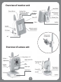
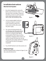
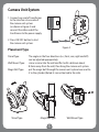
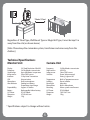
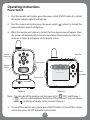
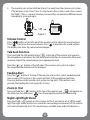
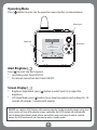
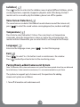
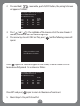
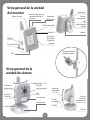
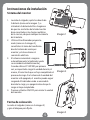
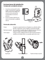
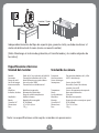
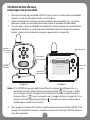
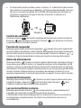
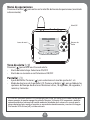
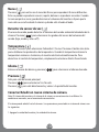
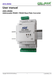
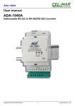
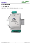
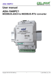
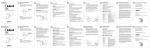
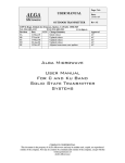
Digital Video Baby Monitor
Model: SY-VB10D
User Manual
Table of Contents
1.
2.
3.
4.
Important Notes........................................................................2
Overview of Baby Monitor ....................................................3
Installation Instructions..........................................................4
Operating Instructions ...........................................................7
Power Switch..............................................................................7
Volume Control .........................................................................8
Dialogue Function....................................................................8
Feeding Alert..............................................................................8
Zoom In /Out..............................................................................8
Night Light/ Night Vision .......................................................8
Operating Menu........................................................................9
Alert Ringtone ...........................................................................9
Screen Display ...........................................................................9
Lullabies .................................................................................... 10
Sound Sensor Detection ..................................................... 10
Temperature ............................................................................ 10
Language.................................................................................. 10
Exit .............................................................................................. 10
Pairing/Newly-added Camcorder System .................... 10
5. Troubleshooting .................................................................... 12
1
Important Notes:
Before using a Digital Vision Baby Monitor, please read this
User Manual very carefully and keep it properly for future
reference. Incorrect use of the product may cause damage
to the product or cause bodily injury.
*
*
*
*
*
*
*
*
*
Please keep the transformer and wires away from the children.
Please be careful to protect the transformer and wires to avoid
tearing or man-made damage.
Please avoid danger of suffocation caused by children playing with
the wires.
Please use the recommended transformer for the products, the use
of other substandard transformer s may lead to mechanical
damage.
Please ensure that the transformer voltage rating matches the
requirements of relevant countries and regions.
Do not put the monitor into the bedding, drawer, or cover it with a
cloth.
Do not wet the monitor or immerse it into water or other liquids.
Do not place the monitor outdoors or at open space, or expose it
hot places such as furnace, stove, etc. .
Do not dismount the unit. This can cause damage to the internal
parts.
2
Overview of monitor unit
strap Holder
Channel Button
Feeding Alert
Zoom in/out /Pairing
Talk Back
/Exit Button
Multi Purpose
Stand/clip
Power LED
Li Battery Door
Menu
Speaker
ON/OFF
4direction control
/volume control
DC IN Jack
Velcro System
or Wall Mount
MIC
Overview of camera unit
Swing Angle +/-18˚
Volume +
/light button
Volume /Pairing
Night Vision LEDs
Flipping Angle
+25˚ /-35˚
MIC
Night Light
Light Sensor
Power LED
Temperature
sensor Vents
ON/OFF
DC IN Jack
Speaker
3
Installation Instructions
Monitor Unit System
1.
Raise the hanging buckle, remove the
battery cover (as shown in Figure 1), and
then put in the li-ion battery, make sure
the battery contacts are well connected
to the metal contact points on the
chassis, then close the battery cover.
2.
Use the recommended transformer
(as shown in Figure 2), connect it
to the transformer outlet of the
vision system and the other end to
the power supply.
3.
The system will automatically enter
into charging mode [the green display
indicator will automatically light up].
For first use, charging mode shall be
maintained for at least 4 hours until the
completion of charging. If the monitor unit
system is closed, the monitor can also be
charged, the green display indicator will light up,
and it will put out after the charging is
completed.
4.
Figure 1
Figure 2
Press ON/OFF button to start the monitor unit.
Placement Type
Raise the hanging buckle (as shown in Figure 3), and
then rotate the lock to fix it.
4
Figure 3
Camera Unit System
1. Connect one end of transformer
to the interface at one side of
the camera unit system
(as shown in Figure 4) and
connect the other end of the
transformer to the power supply.
2. Press ON/OFF button to start
the camera unit system.
Figure 4
Placement Type
Stand Type:
Wall Mount Type:
Magic Belt Type:
Stand Type
The angles in the four directions (i.e., front, rear, right and left)
can be adjusted appropriately.
screw a screw into the wall and fix it with a distance about
8-9mm away from the wall, then hang the camera unit system.
put the magic belt through the camera unit system base and tie
it to the cylinder (Noted: it can not be tied to the crib).
Magic Belt Type
5
Wall Mount Type
1Meter/3 Feet
Regardless of Stand Type, Wall Mount Type or Magic Belt Type, it must be kept 1m
away from the crib (as shown above).
[Note: Please keep the camcorder system, transformer and wires away from the
children].
Technical Specifications
Monitor Unit
Display
Frequency
Signal range
Image sensor
Intercom
VOX
Microphone
Alert indicator
Expandability
Battery
A/C Power
Dimension
Weight
Camera Unit
2.4” Panel Resolution 240x320
2.4GHz Wireless transmission
Up to 300 Meters in open area
Color CMOS sensor
2- Way Voice Transmission
Voice acivation
Built in microphone
Feeding,Low Battery,
Temperature,signal range.
Support 4 Cameras
Rechargeable Lithium battery
DC 6V 800mA
9.7X10.4x3.8cm
137g
Frequency
Night version
Image sensor
Switches
Temperature
Lullabies
Mood light
Microphone
Mounting
A/C Power
Dimension
Weight
* Specifications subject to change without notice.
6
2.4GHz Wireless transmission
6 IR LEDs
Color COMS sensor
Power, Volume control,
Pairing , Light on/off
Built -in Temperature sensor
Preset Lullabies
blue color
Built in Microphone
Velcro system or wall mount
DC 6V 800mA
7.0X12.8x7.2cm
120g
Operating Instructions
Power Switch
1.
Start the monitor unit system, press the power switch ON/OFF, when it is started,
the power indicator (green) will light up.
2.
Start the camera unit system, press the power switch [
power indicator (green) will light up.
3.
When the monitor unit system is started, the iCore logo screen will appear, then
the system will automatically enter into monitoring status mode, the status bar
as shown in Figure 6 will appear on the display screen.
] , when it is started, the
Volume + /
Night Light
Status Bar
Power Switch
Volume -/
Pairing
Waiting for Connecting...
Sound
Adjustment
Power Switch
Figure 5
Figure 6
Note: The status bar of the monitor unit has been set to [
OFF] and Channe 1
[
] . when it is delivered from the factory. If the Channel 1 is not set, please
press [
] at the top of display screen to select Channel 1.
4.
To turn off the monitor unit system, press ON/OFF button, to turn off the camera
unit system, press ON/OFF button for two seconds.
7
5.
The monitor unit system shall be at least 1m away from the camera unit system,
if the distance is less than 1m or it is too close to the system, it will utter a sound
like “BeBe”. (This is a normal situation, because they are placed in different rooms
according to system design).
1M
Waiting for Connecting...
Figure 7
Volume Control
Press [
] button at the left side of the monitor unit to adjust the sound volume.
Press [ ] to increase the sound volume. Press [ ] to decrease the sound volume.
The display can show the sound volume degree.
Talk back Function
Press and hold the talk back function [
] at the top of the monitor unit speak to
the microphone and release the talk back function button to receive the other one’s
response. Adjust the sound volume to an appropriate level.
Press the [ ] [ ] button at the left side of the camera unit system to adjust
the sound volume and receive the dialogue.
Feeding Alert
Press the [ ] button at the top of the monitor unit system, select predetermined
time or press OFF to close it, the system will alert at the predetermined time.
Press any button on the monitor unit system to stop alert. If the button is not
pressed, the feeding alert will repeat for 3 times.
Zoom In /Out
Press and hold the [
] button at the top of the monitor unit , [ ] will appear on
the status bar. You can press [
] to set appropriate position for monitoring.
Night Light/Night Vision
Press and hold [
] button on the camera unit for 3 seconds to on or off the night
light The night vision function can sense the surrounding environment of the camera
unit and automatically start. The monitoring is available even under full darkness.
8
Operating Menu
Press [
] button to enter into the operation menu interface (as shown below):
Menu Input
Lullabies
Menu Icon
Lullaby 2
Arrow Keys
Lullaby 3
Lullaby 4
Lullaby 5
Alert Ringtone [
]
Screen Display [
]
Press [ ] to enter into alert ringtone:
* Low battery alert: Select ON/OFF
* No network connection alert. Select ON/OFF
*
*
Brightness Adjustment: press [ ] button to select levels1-5 to adjust the
brightness.
LCD Sleep Mode: press [ ] button to set sleep time options such as Keep On, 10
seconds, 30 seconds, 1 minute and 3 minutes.
BM0903 has a built-in VOX function, after entering into the standby mode,for energy saving, the
vision system will turn off the display screen, meanwhile, the VOX function will automatically
start to detect the ambient sound volume around the camera unit,when it reaches a certain
extent, the VOX function will start the monitor unit in standby mode.
9
Lullabies [
]
Press [ ] button to enter into the Lullabies menu to play 8 different lullabies, which
can be played once, repeated, stopped or played in order. After being started, if
monitor unit is no need to play the lullabies, please turn off the speaker.
Voice Sensor Detection [
]
The sound sensor can detect the ambient sound volume around the camera unit,
press [
] to select the sound volume sensing degrees(low, medium and high).
Temperature [
]
Press Scale to select Fahrenheit / Celsius. Press min/max to set temperature
commands, when the temperature is above or below the set temperature, the
monitor will alert. Meanwhile, you can select Alert to set Prompt or Not Prompt.
Language [
]
Enter into the language screen, press [
Exit [
Press [
Press [
] to select the language.
]
] to select Yes / No button to exit or maintenance- the window.
] to directly exit and return to the monitoring screen.
Pairing/Newly-added Camera unit System
Note: The monitor unit system and camera unit system have been paired when they are delivered
from the factory. Under normal circumstances, it is not recommended to re-pair them.
The system can support up to 4 camera unit, the operations for adding
camera unit system are as follows:
1. Turn off all monitor unit and camera unit.
10
2.
Press and hold [
] , meanwhile, push ON/OFF button, the pairing list screen
will appear as follows:
Press Up/Down button to select channel
Press Left/Right button to set
Press Ok button to entry
Status
CH1
Pair
Del
Paired
CH2
Pair
Del
Null
CH2
Pair
Del
Null
CH2
Pair
Del
Null
Exit
3.
4.
Press [ ] and [
] at the right side of the camera unit at the same time for 2
seconds, and release after the indicator lights up.
Press arrow keys to select Ch2 and Pair, press [
] and the following screen will
appear:
Pairing succeed Ch2 is selected
Press OK button to back Menu
Press [ ] again, Ch2 Paired will appear in the system, it means that the CH2 has
been successfully paired. It is as shown as follows:
Press Up/Down button to select channel
Press Left/Right button to set
Press Ok button to entry
Status
CH1
Pair
Del
Paired
CH2
Pair
Del
Paired
CH2
Pair
Del
Null
CH2
Pair
Del
Null
Exit
Press EXIT and press [
5.
] again to return to the screen of monito unit.
Repeat steps 1-4 to pair Ch3 and Ch4.
11
Troubleshooting
If you are not getting any signal at all :
* Make sure the camera and the monitor are turned on
* Make sure the power plugs are pushed all the way in
* Check that the channel on the camera and the monitor are set to the same number. If you
have seen the opening screen, but nothing afterwards
* Please check if your Camera unit is turned on. The green Power LED will light up and
indicated the system is on.
* Make sure the Camera unit and Monitor Unit are within range of each other. For trouble
shooting purpose, you should remove all the obstacles between two units,keep shortest
distance.
* Please remove the battery and unplug the A/C adaper. Wait for 10 minutes. Plug the A/C
adapter back to the Monitor Unit and retry to power on the Monitor Unit.
* If all above steps fail, you are advised to pair the Monitor Unit and Camera Unit. Please
following the steps mentioned in Pairing/New Added Camera Unit.
FCC Statement
WARNING: Modifications and authorized by the manufacturer may void users authority to operate this
device.
This equipment has been tested and found to comply with the limits for a Class B digital device,
pursuant to Part 15 of FCC Rules. These limits are designed to provide reasonable protection against
harmful interference in a residential installation. This equipment generates, uses, and can radiate radio
frequency energy and, if not installed and used in accordance with the instructions, may cause harmful
interference to radio communications.
However, there is no guarantee that interference will not occur in a particular installation. If this
equipment does cause harmful interference to radio or television reception, which can be determined
by turning the equipment off and on , the user is encouraged to try to correct
the interference by one or more of following measures :
*
Reorient or relocate the receiving antenna.
*
Increase the separation between the equipment and receiver.
*
Connect the equipment into an outlet on a circuit difference from that to which the receiver is
connected.
*
Consult the dealer or an experienced radio/TV technician for help.
This device complies with part 15 of the FCC Rules. Operation is subject to the following two conditions:
1. This device may not cause harmful interference, and
2. This device must accept any interference received, including interference that may cause
undesired operation.
This equipment complies with FCC Radiation Exposure Limits set forth for an uncontrolled
environment. This equipment should be installed & operated between with minimum distance 20 cm
the radiator and your body.
12
Made in China
DECLARATION OF CONFORMITY
Manufacturer Name: Satyatrade S. L.
Address: Pol. Ind. La Raya. C/ Guadalquivir, 2.
Camarma de Esteruelas, 28816 Madrid
Tel: 902 430 967
Fax: 91 8864285
NIF: B83254763
Manufacturing country: China
Sytech® SY-VB10D complies with the following directives:
CE standard:EMC Directive 1999/5/EC EN 301 489-1 v1.1.1 (2008-04)
EN 301 489-17 V2.1.1 (2009-05)
Radio Spectrum Directive : EN 300 328 V1.7.1 (2006-10)
Safety Directive :
EN 60065 :2002+A1 :2006+A11 :2008
Health Directive :
EN 62311 :2008
ROHS standard:2002/95/EC Restriction of Hazardous Substance
Signed: Ajeet Nebhwani Utamchandani
Sole Administrator
Cámara de vigilancia
con monitor digital
Modelo: SY-VB10D
Manual de usuario
Índice
1.
2.
3.
4.
Notas importantes ...................................................................2
Vista general del monitor de bebés...................................3
Instrucciones de instalación .................................................4
Instrucciones de uso................................................................7
Interruptor de encendido......................................................7
Control de volumen.................................................................8
Función de diálogo ..................................................................8
Alerta de alimentación ...........................................................8
Aumento/Disminución...........................................................8
Luz nocturna/ Visión nocturna ............................................8
Menú de operaciones .............................................................9
Tono de alerta ............................................................................9
Visualización de la pantalla...................................................9
Nanas ......................................................................................... 10
Sensor de detección de sonidos ...................................... 10
Temperatura ............................................................................ 10
Idioma........................................................................................ 10
Salir............................................................................................. 10
Conectar/Añadir un nuevo sistema de cámara .......... 10
5. Resolución de problemas ................................................... 12
1
Notas importantes
Antes de utilizar el Monitor digital de visión de bebés, lea
este Manual de usuario con cuidado y guárdelo adecuadamente para futuras consultas. El uso incorrecto del
producto puede causar daños materiales o lesiones.
*
*
*
*
*
*
*
*
*
Mantenga el transformador y los cables alejados de los niños.
Tenga cuidado de proteger el transformador y los cables de
desgastes o daños causados.
Evite el peligro de asfixia causado cuando los niños juegan con los
cables.
Utilice el transformador recomendado para los productos, el uso
de otros transformadores no adecuados puede provocar daños
mecánicos.
Asegúrese de que el voltaje del transformador coincide con los
requisitos de los países y regiones correspondientes.
No coloque el monitor encima de la ropa de cama, cajón ni lo
cubra con una tela.
No moje el monitor ni lo introduzca en agua u otros líquidos.
No coloque el monitor en el exterior en espacios abiertos, ni lo
exponga a lugares cálidos como radiadores, estufas, etc.
No desmonte la unidad. Esto puede causar daños en las partes
internas.
2
Vista general de la unidad
del monitor
Alerta de alimentación
Botón de canal
Aumentar/disminuir/
Conectar
Sujetacintas
Soporte
multiposición
/Clip
Responder
/Botón Salir
LED de encendido
Tapa de batería
de litio
Menú OK
Altavoz
Control de 4
direcciones
/Control del
volumen
ON/OFF
Clavija de DC IN
Sistema de velcro o
montaje en pared
MIC
Vista general de la
unidad de cámara
Volumen +/
botón de luz
Volumen -/
Conexión
Ángulo de giro +/- 18˚
LEDs de
visión nocturna
MIC
Luz nocturna
Sensor de luz
Ángulo de
basculación
+25˚ /-35˚
LED de
encendido
Ranuras
del sensor
de temperatura
ON/OFF
Clavija de DC IN
Altavoz
3
Instrucciones de instalación
Sistema del monitor
1.
2.
3.
4.
Levante el colgador, quite la cubierta de
la batería (como en la imagen 1), e
introduzca la batería de litio. Asegúrese
de que los contactos de la batería están
bien conectados a las clavijas metálicas
de la carcasa, después coloque la cubierta
de la batería.
Utilice el transformador proporcionado (como en la imagen 2),
conéctelo a la toma de transformador del sistema de visión por
monitor y el otro extremo al
suministro eléctrico.
El sistema comenzará a cargarse
automáticamente [el indicador verde
se encenderá automáticamente].
Cuando utilice el SY-VB10D por primera
vez, es importante cargar la unidad durante, al
menos, 4 horas hasta que se haya completado el
proceso de carga. Si el sistema de la unidad del
monitor está apagado, el monitor puede seguir
cargando. El indicador verde se encenderá
durante la carga y se apagará antes de que la
carga se haya completado.
Presione el botón ON/OFF para iniciar la unidad
del monitor.
Imagen 1
Imagen 2
Forma de colocación
Levante el colgador (como en la imagen 3)
y gire el bloqueo para fijarlo.
4
Imagen 3
Instrucciones de instalación
Sistema de la unidad de cámara
1.
2.
Conecte un extremo del transformador al sistema de la unidad de
cámara (como en la imagen 4) y
conecte el otro extremo del
transformador al suministro
eléctrico.
Presione el botón ON/OFF para
Iniciar el sistema de la unidad de
cámara.
Imagen 4
Forma de colocación
De pie:
Montaje en pared:
Cinta mágica:
Tipo de pie
El soporte se puede colocar en 4 ángulos (p. ej., delante, detrás,
derecha e izquierda), ajuste el ángulo y la posición deseadas.
Fije un tornillo a la pared y deje una distancia de unos 8-9 mm a
la pared. Cuelgue el sistema de la unidad de cámara.
Coloque el velcro alrededor de la base del sistema de cámara y
sujételo en el cilindro (Nota: no se puede sujetar en la cuna).
Tipo de cinta mágica
5
Tipo de montaje en pared
1 metro / 3 pies
Independientemente del tipo de soporte (pie, pared o cinta), se debe mantener a 1
metro de distancia de la cuna (como se muestra arriba).
[Nota: Mantenga el sistema de grabación, el transformador y los cables alejados de
los niños].
Especificaciones técnicas
Unidad del monitor
Pantalla
Frecuencia
Rango de señal
Sensor de imagen
Intercomunicador
VOX
Micrófono
Indicador de alerta
Ampliación
Batería
Conexión A/C
Dimensiones
Peso
Unidad de la cámara
Panel de 2.4” con resolución de 240x320
Transmisión inalámbrica de 2,4 GHz
Hasta 300 metros en espacio abierto
Sensor de color CMOS
Transmisión de voz bidireccional
Frecuencia
Versión nocturna
Sensor de imagen
Interruptores
Micrófono incorporado
Alimentación, Batería baja
Rango de señal de temperatura
Admite 4 cámaras
Batería de litio recargable
DC 6V 800mA
9,7 x 10,4 x 3,8 cm
137 g
Temperatura
Nanas
Luz de ambiente
Micrófono
Montaje
Conexión A/C
Dimensiones
Peso
Transmisión inalámbrica de 2,4 GHz
6 LED´s de infrarrojos
Sensor de color CMOS
Encendido, Control de volumen,
conexión, luz on/off
Sensor de temperatura incorporado
Nanas preseleccionadas
Color azul
Micrófono incorporado
Sistema de velcro o montaje en pared
DC 6V 800mA
7.0 x 12.8 x 7.2cm
120 g
Nota: Las especificaciones están sujetas a cambios sin previo aviso
6
Instrucciones de uso
Interruptor de encendido
1.
2.
3.
Presione el botón de encendido ON/OFF para iniciar el sistema de la unidad del
monitor. La luz de indicador (verde) se encenderá.
Inicie el sistema de la cámara, presione el botón de encendido [ ]. La luz del
indicador (verde) se encenderá para indicar que la unidad está encendida.
Una vez que se haya encendido la unidad del monitor, aparecerá la pantalla del
logotipo de Sytech y el sistema pasará automáticamente al modo de monitorización. La barra de estado de la imagen 6 aparecerá en la pantalla.
Volumen +/
Luz nocturna
Barra de estado
Interruptor
de encendido
Volumen -/
Conexión
Waiting for Connecting...
Ajuste del
sonido
Interruptor
de encendido
Imagen 5
Imagen 6
Nota: El SY-VB10D incluye por defecto de fábrica la siguiente configuración. La
opción de alerta de Alimentación está desactivada (
OFF) como se indica
en la imagen anterior (imagen 6). El número de Canal de visualización de la
cámara está en [
] como se muestra en la imagen anterior (imagen 6). Si no
aparece el Canal 1, presione el botón [ ] situado en la parte superior de la
pantalla para seleccionar el Canal 1
4.
Para apagar el sistema del monitor, simplemente presione el botón ON/OFF. Para
apagar el sistema de la cámara, simplemente presione el botón ON/OFF durante
unos dos segundos.
7
5.
El sistema del monitor se debe colocar, al menos, a 1 m de distancia del sistema
de la cámara. En caso de que el Monitor y la Cámara estén demasiado cerca uno
de otra, se escuchará un pitido. (El SY-VB10D está diseñado para funcionar en
situaciones normales en las que la cámara y el monitor se colocan en 2
habitaciones diferentes).
1M
Control de volumen
Waiting for Connecting...
Imagen 7
Presione el botón [
] de la parte izquierda del monitor para ajustar el volumen.
Presione [ ] para aumentar el volumen. Presione [ ] para disminuir el volumen.
La pantalla indica el nivel del volumen.
Función de responder
Mantenga presionado el botón de responder [
] situado en la parte superior del
monitor. Hable al micrófono y suelte el botón de responder para recibir la respuesta
del otro lado. Ajuste el volumen a un nivel apropiado. Presione los botones [ ] [ ]
situados en la parte izquierda de la cámara para ajustar el volumen del receptor.
Alerta de alimentación
Presione el botón [ ] situado en la parte superior del monitor. Seleccione la hora a
la que desee que suene la alarma. Las siguientes opciones están disponibles: de 30
minutos a 4 horas en intervalos de 30 min. Presione OFF para desactivar la alerta de
alimentación. El monitor zumbará automáticamente una vez que haya pasado dicho
tiempo. Presione cualquier botón en el monitor para detener la alarma. Si no se
presiona ningún botón, la alerta de alimentación se repetirá 3 veces cada 3 minutos.
Aumento/Disminución
Mantenga presionado el botón [ ] situado en la parte superior del monitor para
ampliar la imagen. Aparecerá [ ] en la barra de estado. Presione [
] para
establecer la posición de monitorización apropiada.
Luz nocturna/Visión nocturna
Mantenga presionado el botón [ ] en la cámara durante, aproximadamente, 3
segundos para encender o apagar la función de luz nocturna.
La función de visión nocturna puede sentir el entorno de la cámara y comenzar la
monitorización automáticamente. Se realiza la monitorización incluso en la
oscuridad total.
8
Menú de operaciones
Presione el botón [
anteriormente):
] para entrar en la interfaz del menú de operaciones (mostrado
Menú/OK
Lullabies
Icono de menú
Lullaby 2
Lullaby 3
Botones de
flecha
Lullaby 4
Lullaby 5
Tono de alerta [
]
Presione [ ] para entrar en el tono de alerta:
• Alerta de batería baja: Seleccione ON/OFF
• Alerta de no conexión a red. Seleccione ON/OFF
Pantalla [
•
•
]
Ajuste del brillo: Presione [ ] para seleccionar el nivel de ajuste de 1 a 5.
Modo de descanso de la pantalla LCD: Presione el botón [ ] para establecer las
opciones del tiempo de descanso: Mantener activo, 10 segundos, 30 segundos, 1
minuto y 3 minutos.
El SY-VB10D tiene una función VOX incorporada con el que, tras entrar en el modo standby para
ahorrar energía, el monitor apagará la pantalla. Mientras, la función VOX comenzará a detectar
automáticamente el volumen del sonido ambiental alrededor de la cámara. En caso de que la
cámara detecte algún sonido, el monitor se encenderá automáticamente y mostrará la imagen.
Si la función VOX está en [off ], está desactivada.
9
Nanas [
]
Presione [ ] para entrar en el menú de Nanas para reproducir 8 nanas diferentes.
Éstas se pueden reproducir una vez, repetir, detener o reproducir en orden. Cuando
la nana empieza a sonar, puede disminuir el volumen del monitor a 0 para que la
nana sólo se escuche desde la cámara y donde esté situado el bebé.
Detector de sensor de voz [
]
El sensor de sonido puede detectar el volumen del sonido ambiental alrededor de la
cámara. Presione [
] para seleccionar los grados del sensor del volumen del
sonido (bajo, medio y alto u off ).
Temperatura [
]
Presione “Formato” para seleccionar Fahrenheit / Cesius. Presione el botón mín./máx.
para establecer los parámetros de temperatura. Cuando la temperatura alcance la
temperatura máxima o la mínima, el monitor alertará automáticamente. Para
desactivar el control de temperatura, simplemente seleccione Alerta Desactivado.
Idioma [
]
Entre en el menú de idioma y presione [
Presione [
] para seleccionar el idioma deseado.
]
Salir para salir del menú principal.
Presione [
] para seleccionar Sí o No salir.
Presione [
] para salir directamente y volver a la pantalla del monitor.
Conectar/Añadir un nuevo sistema de cámara.
Nota: El sistema del monitor y el sistema de la cámara se conectan entre sí en fábrica. En
condiciones normales, no se recomienda reconectarlos.
El sistema puede admitir hasta 4 cámaras. Las operaciones para añadir un sistema de cámara son
las siguientes:
1. Apague la unidad del monitor y la unidad de la cámara.
10
2.
Mantenga presionado el botón [
], mientras, presione el botón ON/OFF.
Aparecerá la lista de elementos conectados:
Press Up/Down button to select channel
Press Left/Right button to set
Press Ok button to entry
Status
CH1
Pair
Del
Paired
CH2
Pair
Del
Null
CH2
Pair
Del
Null
CH2
Pair
Del
Null
Exit
3.
4.
Presione [ ] y [
] de la parte derecha de la cámara al mismo tiempo
durante 2 segundos y suéltelos cuando se enciendan las luces de indicación.
Presione las flechas para seleccionar Ch2 y Conectar, presione [ ]. Aparecerá la
siguiente pantalla:
Pairing succeed Ch2 is selected
Press OK button to back Menu
Presione [
] de nuevo, aparecerá Ch2 Conectado en la pantalla del monitor. Esto
significa que el CH2 se ha conectado con éxito. Consulte la imagen siguiente:
Press Up/Down button to select channel
Press Left/Right button to set
Press Ok button to entry
Status
CH1
Pair
Del
Paired
CH2
Pair
Del
Paired
CH2
Pair
Del
Null
CH2
Pair
Del
Null
Exit
Presione EXIT y presione [
5.
] otra vez para volver a la pantalla del monitor.
Repita los pasos 1-4 para conectar el Ch3 y el Ch4.
11
Resolución de problemas
Si no obtiene señal alguna:
* Asegúrese de que la cámara y el monitor están encendidos.
* Asegúrese de que los enchufes están bien conectados.
* Compruebe que el canal de la cámara y el del monitor están en el mismo número.
Si ha visto la pantalla de inicio, pero después no aparece nada.
* Compruebe si su cámara está encendida. El LED de encendido verde se encenderá e indicará
que el sistema está encendido.
* Asegúrese de que la cámara y el monitor están dentro del rango apropiado del otro. Para
evitar problemas, debe quitar todos los obstáculos entre los dos dispositivos. Intente con
una distancia más corta.
* Quite la batería y desconecte el adaptador A/C. Espere 10 minutos.
* Vuelva a conectar el adaptador A/C al monitor y vuelva a encender el monitor. Si no
funcionan los pasos anteriores, se recomienda que vuelva a conectar la unidad del monitor y
la de la cámara entre sí.
* Siga los pasos mencionados en Conectar/Añadir un sistema de cámara nuevo. Si desea
volver a la configuración de fábrica, mantenga presionado el botón [ ], mientras, presione
on/off, y después presione [ ]. Se restaurará la configuración.
Declaración de la FCC:
ADVERTENCIA:
Las modificaciones no autorizadas por el fabricante pueden anular la autoridad
del usuario para utilizar este dispositivo.
Este equipo ha sido probado para cumplir con los límites del dispositivo digital de clase B, siguiendo la
Parte 15 de las Normas CCF. Estos límites están diseñados para proporcionar una protección razonable
contra las interferencias dañinas en una instalación residencial.
Este equipo genera, utiliza y puede irradiar energía de radio frecuencia y, si no se instala y utiliza de
acuerdo con las instrucciones, puede provocar interferencias dañinas a las comunicaciones de radio. Sin
embargo, no hay garantía de que no ocurra la interferencia en una instalación en particular.
Si este equipo causa interferencias dañinas a la recepción de radio o televisión, que se pueden
determinar encendiendo y apagando el equipo, el usuario puede intentar corregir la interferencia con
una de las siguientes medidas:
* Reoriente o resitúe la antena de recepción.
* Aumente la separación entre el equipo y el receptor.
* Conecte el equipo a un enchufe de un circuito diferente del cual el receptor está conectado.
* Consulte al departamento de servicio técnico de Sytech en busca de ayuda.
Este equipo cumple con el Apartado 15 de la normativa de la Comisión Federal de Comunicaciones. El
uso está sujeto a las siguientes condiciones:
1. Este dispositivo puede no causar interferencias dañinas
2. Este dispositivo debe aceptar cualquier interferencia recibida, incluyendo las interferencias que
pueden provocar usos no deseados.
Este equipo cumple con los Límites de Exposición a Radiación de la FCC establecidos para un entorno
no controlado. Este equipo se debe instalar y utilizar con una distancia mínima de 20 cm entre el
radiador y su cuerpo.
12
Κατασκευάζεται στην Κίνα
DECLARACIÓN DE CONFORMIDAD
Nombre del fabricante: Satyatrade S. L.
Dirección: Pol. Ind. La Raya. C/ Guadalquivir, 2.
Camarma de Esteruelas, 28816 Madrid
Tel: 902 430 967
Fax: 91 8864285
NIF: B83254763
País de fabricación: China
Sytech® SY-VB10D cumple las siguientes directivas:
Estándar CE: Directiva 1999/5/CE de la EMC
EN 301 489-1 v1.1.1 (2008-04)
EN 301 489-17 V2.1.1 (2009-05)
Directiva de Espectro de radio:
EN 300 328 V1.7.1 (2006-10)
Directiva de seguridad:
EN 60065 :2002+A1 :2006+A11 :2008
Directiva de sanidad:
EN 62311 :2008
Estándar ROHS: 2002/95/CE Restricción de sustancias peligrosas
Firmado: Ajeet Nebhwani Utamchandani
Único Administrador