1
ANEXOS
Índice de anexos
ROBOTICS STARTER KIT ................................................................................. i
ESPECIFICACIONES (INGLÉS) ..................................................................... i
sbRIO 9631 .................................................................................................iii
ENOBIO ......................................................................................................... xi
EXTRACTO DEL MANUAL DE USUARIO ................................................... xi
EXTRACTO DE LA API DE ENOBIO (INGLÉS) ............................................xii
CLASES DE LA API DE ENOBIO (INGLÉS) ................................................ xiii
LA CLASE ENOBIO (INGLÉS) ....................................................................xiv
WII REMOTE ............................................................................................... xvii
ESPECIFICACIONES (INGLÉS) ................................................................. xvii
FUNCIONES DE ENOBIO ACCESIBLES .......................................................xix
DIAGRAMAS DE DIAdem ........................................................................... xxiii
DETALLES DE LOS DATOS ADQUIRIDOS .............................................. xxiii
IMÁGENES DE LA DEMO .......................................................................... xxvii
GUÍA DE INICIALIZACIÓN Y PROGRAMA PRINCIPAL ........................... xxvii
PROGRAMA DE TEST ..............................................................................xxx
LA SELECCIÓN DEL CONTROL Y EL OBJETIVO .................................. xxxiii
CONTROL DESDE ENOBIO .................................................................. xxxiv
CONTROL DESDE WII REMOTE ........................................................... xxxvi
CONTROL DESDE TECLADO/RATÓN ................................................... xxxvi
CONTROL DE LA SIMULACIÓN........................................................... xxxvii
DOCUMENTACIÓN DE LA DEMO ............................................................ xxxix
READ ME ................................................................................................... xl
HOW IT WORKS ...................................................................................... xlvi
Figuras ............................................................................................................ li
ROBOTICS STARTER KIT
ESPECIFICACIONES (INGLÉS)
Platform
Size
405 mm x 368 mm x 150 mm
(15.9'' x 14.5'' x 5.9'')
Weight
3.6 kg (7.9 lb)
Battery charge time
1.7 hours
Battery charge time (with the motors turned on)*
1 hour
Battery charge time (with the motors turned off)
4 hours
Assuming that the robot is running the startup application (obstacle avoidance) on a
fully charged battery
*
Ultrasonic Sensor
The Parallax PING))) ultrasonic sensor detects objects by emitting a short
ultrasonic burst and then “listening” for the echo. Under the control of a host
microcontroller (trigger pulse), the sensor emits a short 40 kHz (ultrasonic) burst. This
burst travels through the air at about 1130 feet per second, hits an object, and then
bounces back to the sensor. The PING))) sensor provides an output pulse to the host that
terminates when the echo is detected; hence, the width of this pulse corresponds to the
distance to the target.
i
ANEXOS
Supply voltage
5 VDC
Supply current
30 mA typ; 35 mA max
Range
2cm to 3m
Input trigger
positive TTL pulse, 2 µS min, 5 μs
typ
Echo pulse
positive TTL pulse, 115 µS to 18.5
ms
Echo holdoff
750 μs from fall of trigger pulse
Burst frequency
40 kHz for 200 μs
Burst indicator
LED shows sensor activity
Delay before next measurement
200 μs
Size (H by W by D)
22mm x 46mm x 16 mm
(0.84in. x 1.8in x 0.6 in.)
ii
SECCIÓN
ROBOTICS STARTER KIT
DC Motors
Supply voltage
12V
Torque
300 oz-in.
RPM
152
Encoders
Supply voltage
5V
Cycles per revolution
100 CPR
Pulses per revolution
400 PPR
sbRIO 9631
NI sbRIOsbRIO-9631
9631
Network
Network interface
10BaseT and 100BaseTX
Ethernet
Compatibility
IEEE 802.3
Communication rates
10 Mbps, 100 Mbps, autonegotiated
Maximum cabling distance
100 m/segment
iii
ANEXOS
RSRS-232 DTE Serial Port
Baud rate support
Arbitrary
Maximum baud rate
115,200 bps
Data bits
5, 6, 7, 8
Stop bits
1, 2
Parity
Odd, Even, Mark, Space,
None
Flow control
RTS/CTS, XON/XOFF,
DTR/DSR, None
Processor Speed
NI sbRIO-9611/9631/9641
266 MHz
NI sbRIO-9612/9632/9642 and NI sbRIO96x2XT
400 MHz
Memory
Non-volatile memory
NI sbRIO-9611/9631/9641
128 MB
NI sbRIO-9612/9632/9642 and NI sbRIO96x2XT
256 MB
System memory
NI sbRIO-9611/9631/9641
64 MB
NI sbRIO-9612/9632/9642 and NI sbRIO96x2XT
128 MB
For information about the life span of the nonvolatile memory and about best practices
for using nonvolatile memory, go to ni.com/info and enter the Info Code SSDBP.
iv
SECCIÓN
ROBOTICS STARTER KIT
Xilinx SpartanSpartan-3 Reconfigurable FPGA
Number of logic cells
NI sbRIO-9611/9631/9641
17,280
NI sbRIO-9612/9632/9642 and NI sbRIO96x2XT
46,080
Available embedded RAM
NI sbRIO-9611/9631/9641
432 kbits
NI sbRIO-9612/9632/9642 and NI sbRIO96x2XT
720 kbits
3.3 V Digital I/O
Number of DIO channels
110
Maximum tested current per channel
3 mA
Maximum total current, all lines
330 mA
Maximum tested DIO frequency
10 MHz
Input logic levels
Input high voltage, VIH
2.0 V min; 5.25 V max
Input low voltage, VIL
0 V min; 0.8 V max
Output logic levels
Output high voltage, VOH , sourcing 3 mA
2.7 V min; 3.3 V max
Output low voltage, VOL , sinking 3 mA
0.07 V min; 0.54 V max
Overvoltage protection (maximum 2 pins in overvoltage)
NI sbRIO-961x/963x/964x
at –20 to 55 °C
±20 V
NI sbRIO-96x2XT
at –20 to 85 °C
±20 V
v
ANEXOS
at –40 to –20 °C
±7 V
Posistor (PRG18BB330MS1RB from Murata)
Maximum peak abnormal-condition
current
760 mA
Maximum hold current at 25 °C
36 mA
Maximum hold current at 70 °C
20 mA
Maximum hold current at 85 °C (NI
sbRIO-96x2XT only)
3 mA
Trip current at 25 °C
71 mA
Resistance at 25 °C
33 Ω ±20%
Analog Input
All voltages are relative to AI GND unless otherwise noted.
Number of channels
32 single-ended or 16 differential analog
input channels
ADC resolution
16 bits
Differential nonlinearity
No missing codes guaranteed
Integrated nonlinearity
Refer to the AI Absolute Accuracy Tables
and Formulas.
Conversion time
4.00 μs (250 kS/s)
Input coupling
DC
Nominal input ranges
±10 V, ±5 V, ±1 V, ±0.2 V
Minimum overrange (for 10 V range)
4%
Maximum working voltage for analog
inputs (signal + common mode)
Each channel must remain within ±10.4 V
of common
Input impedance (AI-to-AI GND)
Powered on
vi
>10 GΩ in parallel with 100 pF
SECCIÓN
ROBOTICS STARTER KIT
Powered off/overload
1.2 kΩ min
Input bias current
±100 pA
Crosstalk (at 100 kHz)
Adjacent channels
–65 dB
Non-adjacent channels
–70 dB
Small-signal bandwidth
700 kHz
Overvoltage protection
AI channel (0 to 31)
±24 V (one channel only)
AISENSE
±24 V
CMRR (DC to 60 Hz)
92 dB
Analog Output (NI sbRIOsbRIO-963x/9632XT and NI sbRIOsbRIO-964x/9642XT Only)
Number of channels
4 analog output channels
DAC resolution
16 bits
Type of DAC
String
Output range
±10 V
Operating voltage
Nominal
±10.7 V
Minimum
±10.3 V
Maximum
±11 V
Current drive
±3 mA per channel
Output impedance
0.1 Ω
vii
ANEXOS
Power Limits
Caution Exceeding the power limits may cause unpredictable behavior by the device.
5 V pins (P2, P3, P4, P5)
+5 V ±5%, 2 A max (shared with C Series
modules)
Power Requirements
The NI sbRIO device requires a power supply connected to connector J3. Refer to the
Powering the NI sbRIO Device section in the User Guide for information about
connecting the power supply.
Power supply voltage range
19–30 VDC 6
Power supply current limit
1.8 A
Power connector internal fuse
2 A non-replaceable
Total power requirement = Pint + PDIO + P5V + P CSer , where:
Pint is the consumption by sbRIO internal operation, including integrated I/O
P DIO is the consumption by the 3.3 V DIO
P5V is the consumption by the 5 V voltage output
PCSer is the consumption by installed board-only C Series modules.
Note You must add 20% to the calculated or measured total power requirement to
account for transient and startup conditions.
Maximum Pint
NI sbRIO-961x/9612XT
7.50 W
NI sbRIO-963x/9632XT
7.75 W
NI sbRIO-964x/9642XT
8.00 W
Maximum PDIO
1.28 W
PDIO = Total DIO Current × 3.3 V/0.85
Maximum P5V
11.1 W
P5V = Total 5 V Output Current × 5 V/0.9
viii
SECCIÓN
Maximum PCSer
ROBOTICS STARTER KIT
3.3 W; each installed C Series module consumes
up to 1.1 W.
Example power requirement calculations:
For an NI sbRIO-9642/9642XT with three installed board-only C Series modules, 20 mA
total current through the 3.3 V DIO pins, and 1 A of current through the 5 V output,
calculate the total power requirement as follows:
Pint = 8.00 W
PCSer = 3.30 W
PDIO = 0.08 W
P5V = 5.55 W
Adding 20% for transient conditions, 16.93 W × 1.2 = 20.32 W
Total power requirement = 20.32 W
For an sbRIO-9612/9612XT with one installed board-only C Series module, 330 mA total
current through the 3.3 V DIO pins, and no 5 V output used, calculate the total power
requirement as follows:
Pint = 7.50 W
PCSer = 1.10 W
PDIO = 1.28 W
P5V = 0.00 W
Adding 20% for transient conditions, 9.88 W × 1.2 = 11.86 W
Total power requirement = 11.86 W
Backup battery
3 V lithium coin cell, BR2032 (–40 to 85 °C)
ix
ANEXOS
Para más información sobre características del kit de robótica, dirigirse a los
siguientes enlaces o la página web de National Instruments (www.ni.com):
Paquete de Inicio para NI LabVIEW Robotics (DaNI) para la Educación:
http://sine.ni.com/nips/cds/view/p/lang/es/nid/208018
NI sbRIO-961x/963x/964x and NI sbRIO-9612XT/9632XT/9642XT User Guide:
http://www.ni.com/pdf/manuals/375052c.pdf
NI sbRIO-961x/963x/964x Quick Reference:
http://www.ni.com/pdf/manuals/375062a.pdf
x
ENOBIO
EXTRACTO DEL MANUAL DE USUARIO
Número de
canales
4
Duración de
baterías
8 horas
Salida de datos
Codificación ASCII o
EDF y/o streaming
digital sobre TCP/IP
Entradas
Biopotenciales
(EEG,ECG, EOG)
Ancho de banda
125 Hz
Comunicación
inalámbrica
IEEE 802.15.4
Tiempo de
muestreo
Rango dinámico
efectivo
250 S/s
22 bits
Dimensiones
66 x 55 x 25 mm
DC Offset
Compensación
automática del
offset para cada
canal
Peso
65 gr.
Rechazo a modo
común
96 dB
Rango de operación -45 ºC hasta 125 ºC
Tabla 1: Especificaciones de Enobio
Para más información dirigirse a las páginas de la empresa Starlab
(http://starlab.es/products/enobio) o bien a las siguientes direcciones:
Neuroelectrics
http://neuroelectrics.com/enobio
Enobio User Manual
http://neuroelectrics.com/sites/neuroelectrics.com/files/enobio/UserManualEn
obio.pdf
xi
ANEXOS
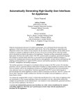
EXTRACTO DE LA API DE ENOBIO (INGLÉS)
The Enobio API consists on a set of classes that permit the access to the
Enobio device and the data that it provides.
The main class to access the device is Enobio. This class provides methods
for opening the device, starting and stopping the data streaming and configuring the
device.
The device configuration is made through the Property class which shall be
set with a valid property name and its value. The valid property names are available as
static strings by the Enobio class (they all start with "STR_PROPERTY_" prefix).
The access to both the data streaming and the device status is made through
a producer-consumer protocol. Enobio implements two producers, one for the data
streaming (Enobio::ENOBIO_DATA) and another one for its status (Enobio::STATUS).
By registering an implementation of the IDataConsumer virtual class with the
Enobio::registerConsumer method the link between the poducer and the cosumer is
made. Thus the Enobio class will call the IDataConsumer::receiveData method of all
registered IDataConsumer implementations every time a new sample is available or
the device status changes.
The actual data or status is passed as a parameter to the
IDataConsumer::receiveData implementation through the PData class. The pointer
returned by the PData::getData method shall be casted to the EnobioData or
StatusData class depending on whether the implementation of the IDataConsumer is
registered to the Enobio::ENOBIO_DATA producer or the Enobio::STATUS one.
The implementation of the IDataConsumer::receiveData method shall take
into consideration that it will be executed from a different thread than teh Enobio one.
So the operations done within the implementation shall be thread-safe.
Another consideration that the IDataConsumer::receiveData implementation
shall take into account is that the data accessed through the PData::getData method is
not accessible out of the scope of that method. That data is deleted inside the Enobio
class when all the IDataConsumer implementations are called.
xii
SECCIÓN
ENOBIO
CLASES DE LA API DE ENOBIO (INGLÉS)
Enobio
This class provides access to the Enobio device and its data
streaming
EnobioData
This class encapsulates an Enobio data sample
IDataConsumer
Base class of a data consumer. It is registered to a data producer
in order to receive its data
IDataProcessor
Base class that allows using the IDataConsumer and
IDataProducer interfaces in order to process incoming data and
pass it to other IDataProcessors that might be registered
IDataProducer
Base class of a data producer. It sends data to all the data
consumers that are registered to it
PData
Generic data class that contains an unspecific data object
Property
Class that encapsulates a property value
StatusData
This class holds the status generated by the Enobio class
Tabla 2: Clases de la API de Enobio
xiii
ANEXOS
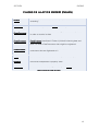
LA CLASE ENOBIO (INGLÉS)
This class provides access to the Enobio device and its data streaming.
More...
#include <Enobio.h
Enobio.h>
Enobio.h>
Inheritance diagram for Enobio:
List of all members.
Public Types
enum
producerIDs { ENOBIO_DATA = 1, STATUS = 2 }
Public Member Functions
Enobio ()
virtual
~Enobio ()
bool
openDevice ()
void
closeDevice ()
void
startStreaming ()
void
stopStreaming ()
bool
ping ()
const Property *
getProperty (const char *propertyName)
bool
setProperty (const Property &property)
virtual IDataConsumer * getDataConsumer (const int id)
virtual IDataProducer *
getDataProducer (const int id)
virtual bool
registerConsumer (const int id, IDataConsumer
&dataConsumer)
xiv
SECCIÓN
virtual bool
ENOBIO
deregisterConsumer (const int id, const IDataConsumer
&dataConsumer)
Static Public Attributes
static const char *
STR_PROPERTY_USB_FIRMWARE_VERSION
static const char *
STR_PROPERTY_ENOBIO_FIRMWARE_VERSION
static const char *
STR_PROPERTY_USB_TRANSMISSION_CHANNEL
static const char *
STR_PROPERTY_ENOBIO_TRANSMISSION_CHANNEL
static const char *
STR_PROPERTY_ENABLE_CHANNEL_1
static const char *
STR_PROPERTY_ENABLE_CHANNEL_2
static const char *
STR_PROPERTY_ENABLE_CHANNEL_3
static const char *
STR_PROPERTY_ENABLE_CHANNEL_4
static const char *
ENOBIO_API_VERSION
Detailed Description
This class provides access to the Enobio device and its data streaming.
This class provides methods for opening the device, starting and stopping the
data streaming and configuring the device.
It inheritates from the base class IDataProcessor so it provides producer
implementations to which IDataConsumer implementations can register to access
both streaming data and device status.
Definition at line 70 of file Enobio.h.
Enobio.h
Para más información sobre la API, las funciones y la programación de este
hardware contactar con la empresa desarrolladora en su página web o por e-mail.
Web:
Web http://starlab.es/
e-mail (formulario):
(formulario) http://starlab.es/contact_us/form
xv
WII REMOTE
ESPECIFICACIONES (INGLÉS)
The Wii Remote (informally known as the Wiimote) is the Wii's main input
device. It is a wireless device, using standard Bluetooth technology to communicate
with the Wii. It is built around a Broadcom BCM2042 bluetooth System-on-a-chip, and
contains multiple peripherals that provide data to it, as well as an expansion port for
external add-ons. The Wii Remote uses (and, at times, abuses) the standard Bluetooth
HID protocol to communicate with the host, which is directly based upon the USB HID
standard. As such, it will appear as a standard input device to any Bluetooth host.
However, the Wii Remote does not make use of the standard data types and HID
descriptor, and only describes its report format length, leaving the actual contents
undefined, which makes it useless with standard HID drivers (but some Wiimote
Drivers exist). The Wii Remote actually uses a fairly complex set of operations,
transmitted through HID Output reports, and returns a number of different data
packets through its Input reports, which contain the data from its peripherals.
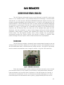
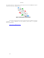
Accelerometer
The Wii Remote includes a three-axis linear accelerometer located on the top
suface of the circuit board, slightly left of the large A button. The integrated circuit is
the ADXL330 (data sheet), manufactured by Analog Devices. This device is physically
rated to measure accelerations over a range of at least +/- 3g with 10% sensitivity.
Figura 1: ADXL330 in a Wii remote
Since the accelerometer actually measures the force exerted by a set of small
proof masses inside of it with respect to its enclosure, the accelerometer measures
linear acceleration in a free fall frame of reference. If the Wii Remote is in free fall, it
will report zero acceleration. At rest, it will report an upward acceleration (+Z, when
horizontal) equal to the acceleration due to gravity, g (approximately 9.8 m/s²) but in
xvii
ANEXOS
the opposite direction. This fact can be used to derive tilt from the acceleration
acceleratio outputs
when the Wii Remote is reasonably still.
Figura 2: Coordinate system used by Wii Remote
Para obtener más información sobre
sobre las especificaciones técnicas, las librerías
existentes y demás información de este hardware, puede
puede acudir a la siguiente
dirección de internet:
http://wiibrew.org/wiki/Wiimote
xviii
FUNCIONES DE ENOBIO
ACCESIBLES
Para realizar el acceso a la API de Enobio, como se ha explicado durante el
proyecto se creó un wrapper donde se programó el acceso a las bibliotecas del
hardware y la exportación de ciertas funciones que serían accesibles desde LabVIEW.
A continuación se detallan cuáles son esas funciones que se han configurado para ser
accesibles desde LabVIEW.
A continuación se muestra el contenido del archivo “main.h” del proyecto de
Microsoft Visual C++ 2010 para la creación del wrapper:
xix
ANEXOS
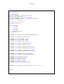
#ifndef _DLL_H_
#define _DLL_H_
#if BUILDING_DLL
# define DLLIMPORT __declspec (dllexport)
#else /* Not BUILDING_DLL */
# define DLLIMPORT __declspec (dllimport)
# define DLLEXPORT extern "C" __declspec (dllexport)
#endif /* Not BUILDING_DLL */
#include "includes\Enobio.h"
#include <extcode.h>
typedef struct{
int Ch1;
int Ch2;
int Ch3;
int Ch4;
long long Tmstp;
} DatosEnobio;
DLLEXPORT int registrar_LVeventos(LVUserEventRef *);
DLLEXPORT int declarar_enobio (void);
DLLEXPORT int abrir_enobio (void);
DLLEXPORT int cerrar_enobio (void);
DLLEXPORT bool enobio_ping (void);
DLLEXPORT int comenzar_streaming (void);
DLLEXPORT int parar_streaming (void);
DLLEXPORT int declarar_consumer_data (void);
DLLEXPORT int declarar_consumer_status (void);
DLLEXPORT int registrar_consumer_data (void);
DLLEXPORT int registrar_consumer_status (void);
DLLEXPORT int configuracion_enobio (void);
DLLEXPORT int transferir_datos (DatosEnobio *);
DLLEXPORT
DLLEXPORT
DLLEXPORT
DLLEXPORT
DLLEXPORT
DLLEXPORT
int leer_status (void);
int leer_ch1 (void);
int leer_ch2 (void);
int leer_ch3 (void);
int leer_ch4 (void);
long long leer_tmstp (void);
DLLEXPORT int configurar_canal_enobio (int, char *, char *);
#endif
xx
SECCIÓN
FUNCIONES DE ENOBIO ACCESIBLES
DatosEnobio es la estructura de datos que se envía normalmente a LabVIEW.
Consta de cuatro datos enteros que corresponden a un valor de cada canal, y un dato
que representa el momento en que fue hecha la medida (para más información
consultar la API de Enobio).
registrar_LVeventos es la función que se utiliza para registrar en la dll el
evento de usuario creado en LabVIEW y poder de esta forma alcanzar la máxima
velocidad de transmisión de datos entre el hardware y el PC.
declarar_enobio esla función que crea una instancia de la clase para poder
acceder al hardware.
abrir_enobio es la función que abre el canal de comunicación entre la Enobio
Box y la diadema.
cerrar_enobio es la función que cierra el canal de comunicación entre la
Enobio Box y la diadema.
enobio_ping es función que consulta un flag de status de Enobio que indica si
la comunicación entre la Enobio Box y la diadema es correcta.
comenzar_streaming es la función que le indica a la diadema que comience el
envío de datos hacia la Enobio Box.
parar_streaming es la función que le indica a la diadema que pare el envío de
datos hacia la Enobio Box.
declarar_consumer_data
declarar_consumer_data es la función que crea una instancia del consumidor
de datos que utiliza Enobio para transferir datos al ordenador (para más información
consultar la API de Enobio, y patrones productor consumidor).
declarar_consumer_status es la función que crea una instancia del
consumidor de estado que utiliza Enobio para transferir datos al ordenador (para más
información consultar la API de Enobio, y patrones productor consumidor).
registrar_consumer_data es la función que registra el consumidor de datos
dentro de la instancia de la clase enobio creada con anterioridad (para más información
consultar la API de Enobio).
registrar_consumer_status es la función que registra el consumidor de estado
dentro de la instancia de la clase enobio creada con anterioridad (para más información
consultar la API de Enobio).
configuración_enobio es la función que configura algunas variables dentro de
la instancia creada de la clase enobio. Por ejemplo las propiedades
STR_PROPERTY_ENABLE_CHANNEL_4.
transferir_datos es la función llamada desde LabVIEW cada vez que se crea
un evento para leer los últimos valores recibidos de los sensores.
xxi
ANEXOS
leer_status es una función que devuelve un código de estado del hardware
adquirido por el consumidor de estados, según lo indicado en la API de Enobio (para
más información consultar la documentación de la API de Enobio, StatusData Class
Reference).
leer_chX
leer_ch son funciones que devuelven el último valor adquirido de un canal
concreto.
leer_tmstp es una función que devuelve el último valor de tiempo en que se
adquirió una muestra del valor de los sensores.
configurar_canal_enobio es la función que permite seleccionar un canal de
transmisión distinto entre los 16 disponibles en la banda que define la norma IEEE
802.15.4.
xxii
DIAGRAMAS DE DIAdem
DETALLES DE LOS DATOS ADQUIRIDOS
En este apartado se van a mostrar gráficos más detallados de las muestras de
datos que se han adquirido en las pruebas que se realizaron con el hardware Enobio.
Se pueden observar en las gráficas los rangos de valores que se pueden
medir con estos sensores, así como hacerse una idea de los tiempos que duran las
acciones de control.
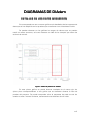
Figura 3: Detalle de pestañeos en DIAdem
DIAdem
En este primer gráfico se puede observar resaltado en el marco rojo los
típicos picos correspondientes a tres guiños que se realizaron durante la fase de
pruebas del proyecto. Se puede comprobar cómo la respuesta de cada uno de los
canales es más o menos la misma, aumentando unas décimas de mili voltio.
xxiii
ANEXOS
Figura 4: Detalle mirando a la derecha en DIAdem
En esta segunda imagen lo que se resalta es un momento en el que el
usuario mira hacia la derecha. Puede observarse cómo la reacción en el canal 1 es la
de aumentar la tensión ya que la parte más positiva del globo ocular se acerca al
sensor que mide este canal, situado en la posición AF8, mientras que en el canal 4,
situado en la posición AF7, ocurre lo contrario. También se puede observar cómo los
canales 2 y 3, situados en FP2 y FP1 respectivamente, no registran cambios
significativos, o por lo menos fácilmente observables y medibles.
xxiv
SECCIÓN
DIAGRAMAS DE DIAdem
Figura 5: Detalle mirando a la izquierda en DIAdem
Por último, en este último detalle se remarca un momento en el que el
usuario mira hacia la izquierda, y se pueden observar parecidos resultados a la acción
de mirar a la derecha comentada antes.
xxv
IMÁGENES DE LA DEMO
GUÍA DE INICIALIZACIÓN Y PROGRAMA
PRINCIPAL
El programa al lanzarlo se arranca con una serie de ventanas que le indican al
usuario cómo debe conectar y configurar el hardware para poder ponerlo en
funcionamiento.
Esta forma de arrancar se diseñó porque los días de las presentaciones de
NIDays no se sabía quién o quiénes iban a poder estar informando sobre la demo, o
arrancándola para hacerla funcionar.
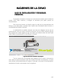
A continuación se pueden observar una serie de imágenes en las que se
puede apreciar cómo son estas ventanas de arranque. Se han incluido también algunas
del programa en versión inglesa ya que se tuvieron que traducir todos los textos para
poder realizar la presentación en los NIDays en Austria.
Figura 6: Ventana de inicialización del
del programa
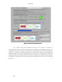
Tras la consecución de mensajes que aseguran que el usuario va llevando a
cabo todos los pasos necesarios para que la demo funcione correctamente, se cierra
esta ventana y automáticamente se carga el VI principal, y se pone en funcionamiento,
obteniendo el usuario una ventana como la siguiente.
xxvii
ANEXOS
Figura 7: Panel
Panel principal pestaña de control
A través de las pestañas, el usuario puede seleccionar el tipo de control en
esta ventana principal, conectarse al hardware de Enobio en la pestaña de “Enobio
Status”, o lanzar un programa de test y entrenamiento para aprender a utilizar Enobio
para el control de DaNI. A continuación pueden verse imágenes de las otras dos
pestañas de este cuadro de mandos principal.
Figura 8: Panel principal, pestaña de conexión de Enobio
xxviii
SECCIÓN
IMÁGENES DE LA DEMO
Figura 9: Panel principal, pestaña de test
Desde esta pestaña se lanza el programa de test y entrenamiento.
xxix
ANEXOS
PROGRAMA DE TEST
A partir de esta última pestaña el usuario puede lanzar el programa de test
que debe utilizar para aprender cómo funciona el control de DaNI a través de Enobio.
Este programa se ejecuta en paralelo con el programa principal, como hacen
el resto de subprogramas, de forma que la ventana del programa principal siempre es
visible.
A continuación se muestran las imágenes del sub programa de test.
Figura 10:
10: Panel de test, pestaña de conexión
En esta primera pestaña del programa de test se le explica al usuario cómo
han de colocarse los sensores, cómo abrir la conexión con el hardware desde el
programa principal y cómo comenzar el streaming de datos hacia el PC. También
puede comprobarse mediante unos indicadores una medida de los tiempos de
adquisición, para conocer la frecuencia de muestreo de las señales.
xxx
SECCIÓN
IMÁGENES DE LA DEMO
Figura 11:
11: Panel de test, pestaña de señales
En esta segunda pestaña el usuario puede comprobar en unos paneles la
adquisición de las señales de cada canal, donde se muestran las señales sin filtrar, y
también se muestra más abajo otro gráfico donde el usuario puede ver la señal de
referencia que se utilizará para calcular las órdenes de giro.
xxxi
ANEXOS
Figura 12:
12: Panel de test, pestaña de control
En el último panel del programa de test se le explica al usuario el
funcionamiento básico del auto calibrado de los canales y la estrategia de control. Se
muestran unos leds para que el usuario sea consciente de qué está haciendo el
programa y pueda ser capaz de detectar si algún canal tiene un funcionamiento
anómalo debido a una mala colocación de los sensores o cualquier otra causa. Se
añaden también unos indicadores que informan al usuario de la orden que se le estaría
mandando al robot en caso de que se estuviese realizando un control real o simulado
del robot.
xxxii
SECCIÓN
IMÁGENES DE LA DEMO
LA SELECCIÓN DEL CONTROL Y EL OBJETIVO
Dese la ventana principal del programa, en la pestaña de control, se puede
seleccionar tanto el método de control como el objetivo que se desea controlar. Una
vez seleccionado en los menús, se lanzan los programas correspondientes
seleccionados una vez se aprieta el botón “Run DaNI Program” de la pestala de
control.
A continuación de muestran las imágenes de estos menús.
Figura 13:
13: Pestañas de selección de control
Figura 14:
14: Pestañas de selección de objetivo
xxxiii
ANEXOS
CONTROL DESDE ENOBIO
Los paneles del programa para el control desde Enobio se parecen bastante a
los paneles del programa de test, aunque más sobrios ya que se pretende mostrar al
usuario la información indispensable para que sea fácilmente visible y no le distraiga
del control del robot.
Pueden verse imágenes de los paneles a continuación.
Figura 15:
15: Panel de Enobio, pestaña de conexión
En este primer panel el usuario puede comprobar la velocidad de adquisición y
la frecuencia de muestreo.
Figura 16:
16: Panel de Enobio, pestaña de señales
En este segundo panel el usuario puede comprobar el valor de las dos señales
que manejará el programa para el control de las órdenes del usuario.
xxxiv
SECCIÓN
IMÁGENES DE LA DEMO
Figura 17:
17: Panel de Enobio, pestaña de control
En este último panel se le indica al usuario mediante un led el estado de
calibración de las señales, para que sepa a partir de qué momento puede mandar
órdenes al robot, una barra que le indica el tiempo restante para generar la orden de
control, y dos indicadores que le muestran las señales que se están enviando en este
momento al robot.
xxxv
ANEXOS
CONTROL DESDE WII REMOTE
En este caso se lanza una ventana donde el usuario puede ver todos los
sensores del mando y sus valores. También tiene un indicador que le muestra las
velocidades que le van a ser enviadas al robot.
A continuación se muestra una imagen de la ventana principal del control
mediante Wii Remote.
Figura 18:
18: Panel de WiiRemote
CONTROL DESDE TECLADO/RATÓN
Se trata de una ventana muy sencilla con varios botones que no pueden ser
presionados a la vez y un control de velocidad.
Se muestra una imagen a continuación.
Figura 19:
19: Panel de control por teclado/ratón
xxxvi
SECCIÓN
IMÁGENES DE LA DEMO
CONTROL DE LA SIMULACIÓN
En el control de la simulación se arranca el motor de simulación que trae el
módulo de LabVIEW Robotics, y se carga un entorno con el modelo del robot. Se lanza
también una ventana que recoge en un gráfico la simulación de los datos recibidos por
el sensor de ultrasonidos.
Se muestra a continuación una imagen de entorno de simulación y la
simulación de los datos del sensor.
Figura 20:
20: Entorno de simulación 3D
Figura 21:
21: Simulación de los datos del sensor de ultrasonidos
xxxvii
DOCUMENTACIÓN DE LA DEMO
Como ya se ha comentado en el escrito del proyecto, la demo fue enviada a
Austria para su presentación en la keynote de los NIDays de dicho país. Se tuvieron
que traducir todos los textos del programa así como crear una documentación
explicativa sobre el funcionamiento y las instrucciones de instalación y puesta en
marcha de la demo. Esta documentación se adjunta al proyecto en este apartado.
Pueden verse en estos documentos imágenes del programa con los textos
traducidos.
A continuación se pueden ver los textos titulados “How it works” y “Read me” de
este proyecto.
xxxix
ANEXOS
READ ME
LabVIEW – Enobio
Installation Procedure
To run this project, first you have to install LabVIEW 2011 + LabVIEW
Robotics 2011 + LabVIEW FPGA.
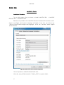
Because of a problem with LabVIEW Robotics Simulation Environment, don’t
forget to configure your System Language as English. To do this, you have to go
“Start>>Control Panel>>Region and Language”, in the Tab “Formats” select English
(United States).
Figura 22:
22: Selección de idioma del sistema operativo
This is important to make Simulated DaNI work.
After this, copy all files located in “Enobio_LIBS” to system folder:
xl
SECCIÓN
For
DOCUMENTACIÓN DE LA DEMO
Windows
32
bits:
destination
folder
should
be
64
bits:
destination
folder
should
be
C:\Windows\System32
For
Windows
C:\Windows\SysWOW64
Last, copy the folder proyecto_2.2 to the root folder.
Running the project
Open the project file C:\proyecto_2.2\proyecto_2.2.lvproj and run the VI
MAIN.VI
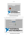
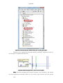
Figura 23:
23: Ventana de proyecto
Follow the instructions to connect with DaNI and start playing the application.
After that the DaNI communication should be launched automatically:
xli
ANEXOS
Figura 24:
24: Panel principal del proyecto (inglés)
(inglés)
After the DaNI_comunication window is launched, if you want to make an
Enobio control, first of all, go to “Enobio Status” tab.
Figura 25:
25: Pestaña de conexión con enobio (inglés)
xlii
SECCIÓN
DOCUMENTACIÓN DE LA DEMO
If you have followed all instructions to reach this point (you have connected
the Enobio box to the computer and you have turned on Enobio head-belt). You just
have to click connect to connect with the hardware, and when “ON” led turns on, you
can click “Start Streaming” and the streaming should start turning on the
“STREAMING” led.
NOTE:
NOTE We detect that sometimes in computers with more than one USB
port, Enobio Box don’t work in all of them, so if you reach satisfactory this point but
when you click “Connect Enobio” the “ON” led doesn’t turn on, try to connect Enobio
Box in other USB port.
At this point all is working!! (but in standby status until required).
xliii
ANEXOS
What to do if all is working?
First of all, launch Enobio Test from “Enobio Test” tab:
Figura 26:
26: Pestaña de test (inglés)
There you have some instructions about how to locate correctly the sensors,
and various test panels to check if the signals are as they supposed to be.
You can practice also to see if you can control it and send the orders you
want.
xliv
SECCIÓN
DOCUMENTACIÓN DE LA DEMO
Running real DaNI
When you try to launch the real DaNI control, you will be alerted to turn on
motors in DaNI platform, which should be off before this moment.
Tips:
In DaNI communication window check that “Emergency Stop” is off to
control DaNI.
DaNI has an emergency automatic action configured. If it detects and
obstacle in front of it, it is going to drive backward until the obstacle goes away. If you
drive DaNI forward to a wall, it will enter in a cycle going forward and backward all the
time until you send stop command.
In manual control from the computer don’t forget to specify a velocity, if not,
even if you press forward, DaNI is going to be stoped.
xlv
ANEXOS
HOW IT WORKS
LabVIEW – Enobio
How it works?
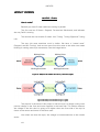
Basically you have 2 state machines working in parallel:
The first one has 3 States: Stopped, Forward and Backwards, and indicates
the way DaNI is moving.
The second one has another 3 states: Not Turning, Turning Right and Turning
Left.
The way this state machines work is similar. We have a “central state”
(Stopped, and Not Turning). And we can move from this state to the other two states
blinking or making some eye movements. See the image below.
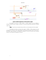
Figura 27:
27: Máquina de estados de avance y retroceso (inglés)
Figura 28:
28: Máquina de estados de giro (inglés)
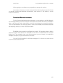
The physics in the base of this project is that the eye is a dipole, having more
positive change in the front and more negative in the back side. The Enobio measure
the voltage in the skin that it’s going to be higher when the front side of the eye its
closer to the sensor and lower in the other case.
Also when we close the eyes, the voltage is incremented due to the muscle
action.
xlvi
SECCIÓN
DOCUMENTACIÓN DE LA DEMO
We are going to use these two properties to manage the actions.
As we have 4 sensors, to have more precision we are going to use all of them
to control forward and backward movements, and sensors in the sides to control
rotation movement.
Forward and Backward movements
For the forward and backward movements, we are going to add all channels,
and manage blinking to send forward or backward instructions. We have to establish a
time to let the user make these blinks, and this time depends on acquiring velocity.
This is a bad behavior we are trying now to solve, but normally in the same computer
the acquiring velocity it’s more or less the same.
By default, the program is configured to acquire 100 samples when a blink is
detected to give time (about two seconds) to the user to make those two or three
blinks, but if the computer has a very fast processor you can change, the acquisition
samples to acquire, to give more time to the user.
You can find this number in both data managers Vis, the test one, and the one
used for control the real DaNI.
xlvii
ANEXOS
Figura 29:
29: Ventana del proyecto, detalle Enobio_main y Enobio_test (inglés)
Search for this Initialize Array showed below in the Block Diagram of both Vis,
and change it if needed (normally not).
Figura 30:
30: Detalle de programación,
programación, vector de avance (inglés)
Note:
Note Be careful changing this number, because if you increase it, the system
can start detecting involuntary blinks as you want to go forward, and the system
xlviii
SECCIÓN
DOCUMENTACIÓN DE LA DEMO
response delay could be too large. The system has to wait to acquire those entire
samples to know what user want to do.
Turning movements
For turning movements, we are going to use two of the four sensors, the two
sensors on the sides. Why? As explained before the eye works as a dipole, these two
sensors are going to read data better than the other two. If we are looking to the right,
the sensor at the right is going to have a positive measurement, and the one on the
left, a negative measurement. And inverse if we look to the left.
For these movements, we don’t need to look two or three times to the sides.
Just one time, and the correct movement to detect this fine is a short saccadic
movement to the side we want to start turning. This means that the movement has to
be quickly and pronounced. The best way to do this is to look at a thing located in the
side we want to turn and after go back to the front.
To check if the user want to turn, the program have to acquire 10 samples
that indicate that the user want to turn. This number can be changed if acquisition
velocity is too fast or too slow. If you are acquiring every 10ms, you have to make a
100ms movement to that side.
Figura 31:
31: Detalle de programación, vector de giros (inglés)
Note:
Note You can find this again in both data managers Vis, the test one, and the
one used for control the real DaNI.
If the user makes a slow movement, the program is going to think that he
made two movements, and DaNI is going to turn the other side. You can start a loop
looking one side to the other and make DaNI drive drunk. This is the most difficult
thing to control and why user had to test and practice.
Limits to compare
After known which and how the program is going to detect the movements,
the last thing you can configure (but it’s tested in several people and looks that works
fine for all, are the limits to compare and detect the events. Are also easy to find and
change. You can find them in both data managers VIs.
xlix
ANEXOS
Figura 32:
32: Detalle de programación, límites
límites de detección (inglés)
By default, the limit to check blinks is 1000, because we are adding 4
channels, and this limit is easily to achieve if we blink consciously and hard to achieve
other way.
Note:
Note If you look up at same time you blink, you can achieve this limit easier.
By default, the limit to check the sides is +250 or -250, because we are
extracting Ch1 and Ch4, this make bigger the difference between look to the front or
the sides. And we check if is positive or negative to know the side we are looking,
positive to the right and negative to the left.
l
Figuras
Figura 1: ADXL330 in a Wii remote ............................................................................ xvii
Figura 2: Coordinate system used by Wii Remote .................................................... xviii
Figura 3: Detalle de pestañeos en DIAdem ............................................................... xxiii
Figura 4: Detalle mirando a la derecha en DIAdem ................................................... xxiv
Figura 5: Detalle mirando a la izquierda en DIAdem ................................................... xxv
Figura 6: Ventana de inicialización del programa ...................................................... xxvii
Figura 7: Panel principal pestaña de control ............................................................ xxviii
Figura 8: Panel principal, pestaña de conexión de Enobio ....................................... xxviii
Figura 9: Panel principal, pestaña de test .................................................................. xxix
Figura 10: Panel de test, pestaña de conexión ........................................................... xxx
Figura 11: Panel de test, pestaña de señales ............................................................ xxxi
Figura 12: Panel de test, pestaña de control ............................................................ xxxii
Figura 13: Pestañas de selección de control ........................................................... xxxiii
Figura 14: Pestañas de selección de objetivo .......................................................... xxxiii
Figura 15: Panel de Enobio, pestaña de conexión ................................................... xxxiv
Figura 16: Panel de Enobio, pestaña de señales ..................................................... xxxiv
Figura 17: Panel de Enobio, pestaña de control........................................................ xxxv
Figura 18: Panel de WiiRemote ............................................................................... xxxvi
Figura 19: Panel de control por teclado/ratón .......................................................... xxxvi
Figura 20: Entorno de simulación 3D ...................................................................... xxxvii
Figura 21: Simulación de los datos del sensor de ultrasonidos .............................. xxxvii
Figura 22: Selección de idioma del sistema operativo ...................................................xl
Figura 23: Ventana de proyecto .................................................................................... xli
Figura 24: Panel principal del proyecto (inglés) ............................................................ xlii
Figura 25: Pestaña de conexión con enobio (inglés) .................................................... xlii
Figura 26: Pestaña de test (inglés) .............................................................................. xliv
Figura 27: Máquina de estados de avance y retroceso (inglés) .................................. xlvi
Figura 28: Máquina de estados de giro (inglés) .......................................................... xlvi
Figura 29: Ventana del proyecto, detalle Enobio_main y Enobio_test (inglés) ......... xlviii
Figura 30: Detalle de programación, vector de avance (inglés) ................................ xlviii
Figura 31: Detalle de programación, vector de giros (inglés) ...................................... xlix
Figura 32: Detalle de programación, límites de detección (inglés) ................................. l
li