1
*
*
*
*
*
*
SAFETY
ASSEMBLY
OPERATION
MAINTENANCE
PARTS LIST
ESPANOL, R 11
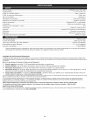
CAUTION: Before using this product,
read this manual and follow all safety
rules and operating instructions.
Sears Brands Management
Corporation,
Visit our website:
769-06626A P00
Hoffman
Estates, iL 60179 U.S.A.
www.craftsrnan.corn
02/11
CALiFORNiA
PROPOSiTiON
65 WARNING
The purpose of safety symbols is to attract your attention to possible
dangers. The safety symbols, and their explanations, deserve your
careful attention and understanding. The safety warnings do not by
themselves eliminate any danger. The instructions or warnings they
give are not substitutes for proper accident prevention measures.
THE ENGINE EXHAUST FROM THIS PRODUCT CONTAINS
CHEMICALS KNOWN TO THE STATE OF CALiFORNiA TO CAUSE
CANCER, BIRTH DEFECTS OR OTHER REPRODUCTIVE HARM.
TABLE OF CONTENTS
Safety Rules ..........................................
Warranty .............................................
Know Your Unit ........................................
Assembly instructions ...................................
Oil and Fuel information .................................
Starting/Stopping
instructions
............................
Operating instructions ...................................
Maintenance and Repair instructions .......................
Cleaning and Storage ...................................
Troubleshooting Chart ...................................
Specifications
........................................
Parts List ............................................
Service Numbers ..............................
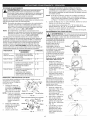
SPARK ARRESTOR
SYMBOL
MEANING
SAFETY
2
4
4
4
5
5
6
7
8
9
10
26
Back Cover
NOTE
NOTE: For users on U.S. Forest Land and in the states of California,
Maine, Oregon and Washington. All U.S. Forest Land and the state of
California (Public Resources Codes 4442 and 4443), Oregon and
Washington require, by law that certain internal combustion engines
operated on forest brush and/or grass-covered areas be equipped with a
spark arrestor, maintained in effective working order, or the engine be
constructed, equipped and maintained for the prevention of fire. Check
with your state or local authorities for regulations pertaining to these
requirements. Failure to follow these requirements could subject you to
liability or a fine. This unit is factory equipped with a spark arrestor, if
it requires replacement, ask your LOCAL SERVICE DEALER to installthe
Accessory Part #753-04926 Muffler Assembly.
ALERT: indicates danger, warning or caution.
Attention is required in order to avoid serious personal
injury. May be used in conjunction with other symbols or
pictographs.
NOTE:
_
Advises you of information or instructions vital to the
operation or maintenance of the equipment.
serious injury to yourself or to others. Always follow the
safety precautions to reduce the risk of fire, electric shock
ANGER:
and
personal Failure
injury. to obey a safety warning will result in
injury to yourself Failureto
WARNING:
and others.
obey
Always
a safety
follow
warning
the safety
can result
precautions
in
to reduce the risk of fire, electric shock and personal injury.
CAUTION:
property damage
Failure
or personal
to obey injury
a safety
to yourself
warning or
may
to result
others.in
Always follow the safety precautions to reduce the risk of fire
electric shock and personal injury.
Read the Operator's Manual and follow all warnings and safety
instructions. Failure to do so can result in serious injuryto the operator
and/or bystanders.
All information, illustrations, and specifications in this manual are based
on the latest product information available at the time of printing. We
reserve the right to make changes at any time without notice.
= IMPORTANT
READ ALL INSTRUCTIONS
SAFETY
BEFORE OPERATING
--
canARNING:
explode if ignited.
Gasoline Take
is highly
the following
flammable precautions:
and its vapors
Store fuel only in containers specifically designed and approved for
the storage of such materials.
=
Avoid creating a source of ignition for spilled fuel. Do not start the
engine until fuel vapors dissipate.
Always stop the engine and allow it to cool before filling the fuel tank.
Never remove the cap of the fuel tank, or add fuel, when the engine
is hot. Never operate the unit without the fuel cap securely in place.
Loosen the fuel tank cap slowly to relieve any pressure in the tank.
Add fuel in a clean, weIFventilated outdoor area where there are no
sparks or flames. Slowly remove the fuel cap only after stopping
engine. Do not smoke while fueling or mixing fuel. Wipe up any spilled
fuel from the unit immediately. Always wipe unit dry before using.
Move the unit at least 30 feet (9.1 m) from the fueling source and site
before starting the engine. Do not smoke or allow sparks and open
flames near the area while adding fuel or operating the unit.
WHILE OPERATING
= Read the instructions carefully. Be familiar with the controls and
proper use of the unit.
• Do not operate this unit when tired, ill, or under the influence of
alcohol, drugs, or medication.
Children and teens under the age of 15 must not use the unit, except
for teens guided by an adult.
All guards and safety attachments must be installed properly before
operating the unit.
inspect the unit before use. Replace damaged parts. Check for fuel
leaks. Make sure all fasteners are in place and secure. Replace parts
that are cracked, chipped, or damaged in any way. Do not operate
the unit with loose or damaged parts.
Carefully inspect the area before starting the unit. Remove all debris
and hard or sharp objects such as glass, wire, etc.
Be aware of the risk of injury to the head, hands and feet.
Clear the area of children, bystanders, and pets. At a minimum, keep
all children, bystanders, and pets outside a 50 feet (15 m) radius;
there still may be a risk to bystanders from thrown objects.
Bystanders should be encouraged to wear eye protection, if you are
approached, stop the unit immediately.
Squeeze the throttle control and check that it returns automatically to
the idle position. Make all adjustments or repairs before using unit.
SAFETY WARNINGS FOR GAS UNITS
_[_
INSTRUCTIONS
= Never start or run the unit inside a closed room or building. Breathing
exhaust fumes can kill. Operate this unit only in a well ventilated
outdoor area.
i
Wear safety glasses or goggles that meet ANSI Z87.1 standards and
are marked as such. Wear ear/hearing protection when operating this
unit. Wear a face or dust mask if the operation is dusty.
Wear heavy, long pants, boots, gloves and a long-sleeved shirt. Do
not wear loose clothing, jewelry, short pants, sandals or go barefoot.
Secure hair above shoulder level.
This unit has a clutch. The tines remain stationary when the engine is
idling, if they do not, have the unit adjusted by a Sears or other
qualified service technician.
Be sure the tines are not in contact with anything before starting the unit.
Use the unit only in daylight or good artificial light.
• Avoidaccidental
starting.
Beinthestarting
position
whenever
pulling
thestarter
rope.
Theoperator
andunitmustbeinastable
position
while
starting.
SeeStarting/Stopping
Instructions.
Usetherighttool.Onlyusethistoolforthepurpose
intended.
Useextreme
caution
whenreversing
orpulling
theunittowards
you.
Donotoverreach.
Always
keepproper
footing
andbalance.
Take
extracarewhenworking
onsteepslopes
orinclines.
Always
holdtheunitwithbothhands
whenoperating.
Keep
afirm
griponthegrips.
Keep
hands,
face,andfeetatadistance
fromallmoving
parts.
Do
nottouchortrytostopthetineswhentheyarerotating.
Donottouchtheengine
ormuffler.
These
partsgetextremely
hot
fromoperation,
evenaftertheunitisturned
off.
Donotoperate
theengine
faster
thanthespeed
needed
tocultivate.
Donotruntheengine
athighspeed
whenyouarenotcultivating.
Always
stoptheengine
whencultivating
isdelayed
orwhenwalking
fromonecultivating
location
toanother.
Ifyoustrikeorbecome
entangled
withaforeign
object,
stoptheengine
immediately
andcheck
fordamage.
Donotoperate
before
repairing
damage.
Donotoperate
theunitwithloose
ordamaged
parts.
Stoptheunit,switch
theengine
tooff,anddisconnect
thesparkplug
formaintenance
orrepair.
Useonlyoriginal
equipment
manufacturer
replacement
parts
and
accessories
forthisunit.These
areavailable
fromyourauthorized
service
dealer.
Useofanyunauthorized
parts
oraccessories
could
leadto
serious
injury
totheuser,
ordamage
totheunit,andvoidyourwarranty.
Keep
unitcleanofvegetation
andothermaterials.
Theymaybecome
lodged
between
thetinesandguard.
Toreduce
firehazard,
replace
faultymuffler
andsparkarrestor,
keep
theengine
andmuffler
freefromgrass,
leaves,
excessive
grease
or
carbon
buildup.
AFTER USE
= Clean tines with a household cleaner to remove any gum buildup. Oil
the tines with machine oil to prevent rust.
OTHER SAFETY WARNINGS
Never store a fueled unit inside a building where fumes may reach an
open flame or spark.
Allow the engine to cool before storing or transporting. Be sure to
secure the unit while transporting.
Store the unit in a dry area, locked up or up high to prevent
unauthorized use or damage, out of the reach of children.
Never douse or squirt the unit with water or any other liquid. Keep
handles dry, clean and free from debris. Clean after each use, see
Cleaning and Storage instructions.
• Keep these instructions. Refer to them often and use them to
instruct other users. If you loan someone this unit, also loan
them these instructions.
SAVE THESE INSTRUCTIONS
" SAFETY & INTERNATIONAL
SYMBOLS
"
This operator's manual describes safety and international symbols and pictographs that may appear on this product.
manual for complete safety, assembly, operating and maintenance and repair information.
SYMBOL
_lll_
MEANING
SYMBOL
MEANING
= THROWN OBJECTS AND ROTATING CUTTER CAN
CAUSE SEVERE INJURY
' SAFETY ALERT SYMBOL
A. L
Indicates danger, warning or cauti0nl Maybe Used in
conjunction with Other symbols or pictographSl
O
Read the operator's
WARNING:
Small objects can be propelled at high
speed, causing injury. Keep away from the rotating rotor.
A
Read the operator's manual(s) and follow all warnings
m
and
WARNING
safety instructions.
- READ OPERATOR'S
Failure to doMANUAL
so can result in
serious injury to the operator and/or bystandersl
• KEEP BYSTANDERS AWAY
WARNING:
Keep all bystanders, especially children
and pets, at least 50 feet (15 m.) from the operating area.
_,HOT SURFACE WARNING
WARNING:
ThroWn0bjects and i0ud noise can cause
Do not touch a hot muffler or cylinder. You may get
burned. These parts get extremely hot from operation.
When turned off they remain hot for a short time.
injury
andHEARING
hearing!oss.PROTECTION
Wear eye prot_tion
o severe
WEAR eye
EYE
AND
meeting ANSI Z87:1_1989standards and ear protection when
operating thisunit. Use a fullface shield when needed.
• OIL
Refer to operator s manual for the proper type of oil.
AlwaYS Use Clean, fresh unleaded fuel
' PRIMER BULB
Push primer bulb, fully and slowly, 10 times.
ON,OFF
STOP
CONTROL
ON / START/RUN
• GARDEN CULTIVATORS - ROTATING TINES CAN
CAUSE SEVERE INJURY
, ON!OFF
STOP
CONTROL
QFF0r
WARNING:
Stop the engine and allow the tines to
stop before installing or removing tines, or before
cleaning or performing any maintenance. Keep hands
and feet away from rotating tines.
STOP
3
CRAFTSMAN
2 YEAR
FULL
WARRANTY
FOR 2 YEARS from the date of purchase, this product is warranted against any defects in material or workmanship.
free replacement if repair is unavailable.
For warranty coverage details to obtain repair or replacement,
visit the web site: www.craftsman.com
This warranty
•
covers
ONLY defects
in material
and workmanship.
Warranty
coverage
Defective product will receive free repair or
does NOT include:
Expendable items that can wear out from normal use within the warranty period, such as blades, tines or belts.
Product damage resulting from user attempts at product modification or repair or caused by product accessories.
Repairs necessary because of accident or failure to operate or maintain the product according to all supplied instructions.
Preventive maintenance, or repairs necessary due to improper fuel mixture, contaminated or stale fuel.
This warranty is void if this product is ever used while providing commercial
services or if rented to another person.
This warranty gives you specific legal rights, and you may also have other rights, which vary from state to state.
Sears Brands Management Corporation, Hoffman Estates, IL 60179
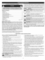
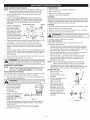
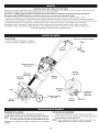
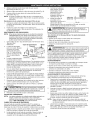
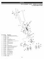
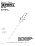
APPLICATION
• Cultivating sod and light to medium soil
Cultivating in garden areas, around trees, etc.
On/Off Switch
Grip
irotUe C//#ontrol
Starter
Rope Grip
Transport
Grip
Fuel Cap
Tine Shield
Handlebar
Knob
Tines
Primer
Air Filter/
Muffler Cover
Wheel
Bracket
Assembly
Spark Plug
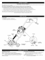
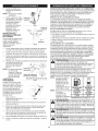
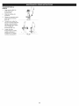
ASSEMBLING
THE UNIT
Before operating, position the unit's handlebars.
NOTE: You may also need to reposition the wheel height before
using the cultivator. Refer to the Adjusting Tine Depth section.
Begin by carefully unpacking the contents and making sure that
nothing is damaged.
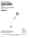
POSITIONING
1.
2.
Muffler
THE HANDLEBARS
Loosen the two knobs on the inside of the handlebars (Fig. 1).
With the unit upright, swing the handlebars up into the
operating position (Fig. 9).
NOTE: Take care not to pinch the throttle cable or switch wires
when positioning the handlebar.
3. Tighten
theknobsto
secure
thehandlebars
in
place(Fig.2).
NOTE:Donotover-tighten
theknobs.
4. Readjust
thethrottle
Handlebar
cableandswitchthe
Knob
wiressotheyaresmooth
andtightagainst
the
handlebar
assembly.
This
willhelpprevent
them
fromcatching
orsnagging
duringnormal
operation.
INSTALLING
THE WHEEL
Bolt
Today's fuels are often a blend of gasoline and oxygenates such as
ethanol, methanol, or MTBE (ether). Alcohol-blended fuel absorbs
water. As little as 1% water in the fuel can make fuel and oil separate.
It forms acids when stored. When using alcohol-blended fuel, use
fresh fuel (less than 60 days old).
Using Blended Fuels
If you choose to use a blended fuel, or its use is unavoidable, follow
recommended precautions:
• Always use the fresh fuel mix explained in your operator's manual
Always agitate the fuel mix before fueling the unit
Washer
/
Handlebar
I_:f_
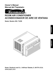
If the wheel bracket assembly
is not installed, or if you ever
need to remove or reinstall it,
follow the ensuing
instructions.
With the unit on its side,
place the wheel bracket
assembly on the
underside of the tine guard (Fig. 3).
Old and/or improperly mixed fuel are the main reasons for the unit
not running properly. Be sure to use fresh, clean unleaded fuel.
Follow the instructions carefully for the proper fuel/oil mixture.
Definition of Blended Fuels
Fig. 1
BRACKET ASSEMBLY
1.
OIL AND FUEL MIXING INSTRUCTIONS
,_
/
Knob
Handlebar
Fig. 2
I_
gloves and a long sleeve shirt when installing the wheel
I WARNING:
To avoid injury from the tines, wear heavy
bracket assembly.
1
--
I WARNING:
i
,A
_
Drain the tank and run the engine dry before storing the unit
Using Fuel Additives
The bottle of 2-cycle oil that came with your unit contains a fuel
additive which will help inhibit corrosion and minimize the formation of
gum deposits. It is recommended that you use our 2-cycle oil with this
unit. If unavailable, use a good 2-cycle oil de-signed for air-cooled
engines along with a fuel additive, such as STA-BIL® Gas Stabilizer or
an equivalent. Add 0.8 oz. (23 ml) of fuel additive per gallon of fuel
according to the instructions on the container. NEVER add fuel
additives directly to the unit's fuel tank.
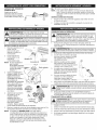
To prevent serious personal injury, the wheel
bracket assemb y must be installed when operating the unit.
2.
Install a carriage bolt through each of the slotted holes in the
wheel bracket and into the tine guard.
3.
On the TOP side of the tine guard, install a lock washer and a
wing nut onto each of the bolts (Fig. 3).
_
reliability, pay strict attention to the oil and fuel mixing
instructions on the 2-cycle oil container. Using improperly
AUTION: For proper engine operation and maximum
mixed fuel can severely damage the engine.
Thoroughly mix the proper ratio of 2-cycle engine oil with unleaded
gasoline in a separate fuel can. Use a 40:1 fuel/oil ratio. Do not mix
them directly in the engine fuel tank. See the table below for specific
gas and oil mixing ratios.
4.
Make sure the square shoulder of the bolts is pushed through
the slotted holes in the wheel bracket. Tighten the wing nuts
(Fig. 3).
NOTE: Do not over-tighten the wing nuts. Loosen the wing nuts to
adjust wheel height.
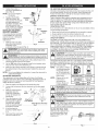
ADJUSTING TINE DEPTH
NOTE:
One gallon (3.8 liters)
of unleaded gasoline
mixed with one 3.2
oz. (95 ml) bottle of 2cycle oil makes a 40:1
fuel/oil ratio.
Tine adjustment will vary depending on the type of soil being
cultivated and how it will be used. Generally, adjusting the tines to
break the soil 4 to 6 inches is recommended for most gardens.
Adjust the tines as follows:
1. Stop the engine and disconnect the spark plug wire.
2. Loosen (do not remove) the two wing nuts on the tine guard
(Fig. 4).
3. Slide the wheel bracket
Tine
assembly down for
Guard
shallower penetration,
and up for deeper tine
penetration.
4. Once the tines are in the
Wing Nut,
desired position, tighten
Lock Washer
the wing nuts, making
sure that the carriage
Wheel Bracket Assembly
bolts are seated properly
Fig. 3
through the bracket.
NOTE:
Dispose of the old
fuel/oil mix in
accordance to
Federal, State and
Local regulations.
5.
Ifthetine depth is
incorrect, repeat steps 2
to 4.
6.
Reconnect the spark plug
wire and continue use.
UNLEADED GAS
1 GALLON US
(3.8 LITERS)
2 CYCLE OIL
3.2 FL. OZ.
(95 ml)
1 LITER
25 ml
MIXING RATIO - 40:1
WARNING:
Gasoline
extremely
flammable.
may explode. Always
stopisthe
engine and
allow it Ignited
to cool vapors
before
filling the fuel tank. Do not smoke while filling the tank. Keep
sparks and open flames at a distance from the area.
,_
WARNING:
Remove
to the
avoid
fuel spray. Never
operatefuel
thecap
unitslowly
without
fuelinjury
cap from
securely in place.
area. Wipe up any spilled fuel immediately. Avoid creating
I_
source of ignition
for spilt
notventilated
start the engine
I aWARNING:
Add fuel
in a fuel.
clean,Dowell
outdoor
until fuel vapors dissipate.
FILLING THE FUEL TANK
Make sure the cultivator is in
a horizontal position when
filling or adding fuel to the
tank (Fig. 5).
DOWN
Fig. 4
Fig. 5
5
OPERATING TiPS
WARNING:
outdoor area. Carbon
Operate monoxide
this unit only
exhaust
in a well-ventilated
fumes can be
lethal in a confined area.
when operating this unit. Do not wear loose clothing or
jewelry. Wear eye and ear/hearing protection. Wear heavy
long pants, boots
andproperly
gloves. to
Doreduce
not wear
WARNING:
Dress
the short
risk ofpants,
injury
sandals or operate barefoot.
WARNING:
Avoid accidental
starting.
Make rope
sure (Fig.
you are
in the starting position
when pulling
the starter
5).
To avoid serious injury, the operator and unit must be
in a stable position while starting.
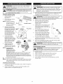
1.
STARTING iNSTRUCTiONS
1. Mix gas with oil. See Oil
and Fuel Mixing
Instructions.
WARNING:
pick-up or carryTothe
prevent
unit while
serious
the personal
engine isinjury,
running.
never
2.
Fill the fuel tank with the
fuel/oil mixture.
NOTE: There is no need to
turn the unit on. The
On/Off Control is in
the ON ( I ) position at
all times (Fig. 6).
3.
4.
Fully press and releasethe
primer bulb 10 times, slowly.
Some amount of fuel should
be visiblein the primer bulb
and fuel lines(Fig. 7).If you
can't see fuel inthe bulb,
press and releasethe bulb as
many times as it takes until
you can see fuel in it.
Crouch in the starting
position (Fig. 8). Do not
squeeze the throttle, pull the
starter rope with a controlled
motion until the unit starts.
Wait and allow the unit to
idle for 60 seconds.
Move the cultivator to the work area prior to starting the engine.
Transport the cultivator by pushing it on its wheels or by
carrying it by the transport grip.
Start ( I )
2.
3.
Start the unit by following the Starting Instructions.
With the engine running and the
tines off the ground, depress the
throttle control to increase the
engine speed.
4.
Holding both of the handlebar grips
firmly, slowly lower the cultivator
until the tines make contact with the
ground (Fig. 9).
As cultivating action begins, pull
back on the cultivator so that the
Fig. 6
Primer Bulb
5.
_ "'
.,.
['
6.
7.
Fig. 7
Starting
Position
5.
Squeeze and hold the
throttle control for an
additional 30 to 60 seconds
to allow the unit to warm up.
NOTE: The unit uses the
INCREDI=PULL TM
starting system, which
significantly reduces the
effort required to start
Fig.8
the engine. You must pull the starter rope out far enough to hear
the engine attempt to start. There is no need to pull the rope
briskly-- there is no harsh resistance when pulling. Be aware that
this starting method is vastly different from (and much easier than)
what you may be used to.
IK.. The engine does not start, go back to step 3.
NOTE: If the unit is hot and fails to start within 3 pulls of the starter
rope, squeeze the throttle control and pull the starter rope
until the unit starts.
STOPPING iNSTRUCTiONS
1.
Release your hand from the throttle control. Allow the engine to
cool down by idling.
2.
Press and hold On/Off Control in the OFF (O) position until
engine comes to a complete stop (Fig. 6).
8.
-4_&l_
WARNING:
caution
when reversing
To prevent
or pulling
seriousthe
personal
unit towards
injury, you.
use extreme
TRANSPORTING
I _IL
\
tines can penetrate the ground,
i
Once the ground has been broken,
_ ......
,
continue at a moderate pace until
,_ ?_
,_.
you are familiar with the controls
and the handling of the cultivator.
Fig. 9
To improve the depth of cultivation,
pull back on the unit as it moves forward to drive the tines
deeper into the ground.
If the tines are digging too deep or not deep enough, adjust
them according to Adjusting Tine Depth.
THE UNiT
stop the engine when operation is delayed or when
I WARNING:
prevent
personal
injury, always
transporting theTounit
from serious
one location
to another
1.
2.
Stop the engine.
Slide the wheel bracket assembly all the way down.
3.
4.
5.
Tilt the unit back until the tines clear the ground.
Push or pull the unit to the next location.
If you need to move the unit over long distances, use the
transport grip.
i
MAINTENANCE
_1
SCHEDULE
WARNING:
To prevent serious injury, never perform
I maintenance or repairs with unit running. Always service
I and repair a cool unit. Disconnect the spark plug wire to
ensure that the un t cannot start.
Perform these required maintenance procedures at the frequency
stated in the table. These procedures should also be a part of any
seasonal tune-up.
NOTE: Some maintenance procedures may require special tools or skills.
If you are unsure about these procedures, take your unit to a
Sears or other qualified service dealer. Call 1=800=4=MY=HOME®
for more information.
NOTE:
Maintenance, replacement, or repair of the emission
control devices and system may be performed by a Sears
or other qualified service dealer. Call 1-800-4-MY-HOME®
for more information.
In order to assure peak performance of your engine, inspection of the
engine exhaust port may be necessary after 50 hours of operation. If
you notice lost RPM, poor performance or general lack of acceleration,
this service may be required. If you feel your engine is in need of this
inspection, refer service to a Sears or other qualified service dealer.
Call 1=800=4-MY-HOME® for more information. DO NOT attempt to
perform this process yourself as engine damage may result from
contaminants involved in the cleaning process for the port.
FREQUENCY
MAINTENANCE
Before starting
engine
Fill fuel tank with fresh fuel
REQUIRED
SEE
p. 5
Every 10 hours
Every 25 hours
Clean and re-oil air filter
Check and clean spark arrestor
Check spark plug condition and gap
p. 7
p. 8
p. 8
Every 50 hours
Inspect exhaust port and spark
arrestor screen for clogging or
obstruction
p. 8
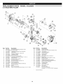
TINE REMOVAL AND REPLACEMENT
All 4 tines should be replaced at the same time because they will
wear evenly through normal use. Work on one side at a time.
Press and hold the Start (0/Stop (O) Control in the Stop (O)
position until the unit
Tine
comes to a complete stop
and disconnect the spark
plug boot from the plug.
NOTE: It may be necessary
to lay the cultivator
back in a horizontal
position on a flat level
surface with the
Cultivator Front
Click Pin
handles touching the
Fig. 10
ground.
2.
Remove the click pin from Hubs on back side (not shown)
each end of the tine shaft.
Slide the tines off of the
shaft (Fig. 10).
3.
Clean and oil the shaft.
The tines are stamped "A" or "B." The tine order should be "B, A,
B, A" from left to right when facing the cultivator from the front.
6.
Secure the new tines to the shaft with click pins. It may be
necessary to wash the dirt off the tines and shaft to help during
this entire process.
AIR FILTER MAINTENANCE
_
The condition of the air filter is
important to the operation of the
unit. A dirty air filter will restrict air
flow and change the air/fuel
mixture. This is often mistaken for Screws
an out of adjustment carburetor.
Check the condition of the air filter
before adjusting the idle speed
screw. Referto Air Filter
Maintenance.
When you are reinstalling
tines, lay out the tines and
compare them to those
shown in Figure 11. Note
"A" Tine
specifics about each tine:
Fig. 11
its hub, curvature and
lettering ("A" or "B"). This will help make sure that you are
placing the correct tines in the correct order.
NOTE: If you look closely, you can see a slight curvature in the tine
tips. These curves should point toward the front of the
cultivator when the tines are installed. Figure 11 shows the
curve in each tine.
5.
Using Figures 10 and 11 for reference, slide on the new tines
with the hubs facing outward.
,Screws
Removing the Air
Filter/Muffler
Cover
Remove the four (4) screws
securing the air filter/
muffler cover (Fig. 12). Use
a flat blade or T20 Torx bit
screwdriver.
2.
Pull the cover from the
engine. Do not force.
Cleaning the Air Filter
Failure to maintain your air
filter properly can result in
poor performance or can
cause permanent damage to
your engine.
1. Remove air filter/muffler
cover. Refer to Removing
the Air Filter/Muffler
Cover above.
Fig. 12
1.
2.
1.
4.
WARNING:
your
unit off andTo
allow
avoidit to
serious
cool before
personal
youinjury,
cleanalways
or service
turn it.
Turn cover over and look
inside to locate the air filter.
Remove the air filter from
inside the air filter/muffler
cover (Fig. 13).
3.
Wash the filter in detergent
and water (Fig. 14). Rinse
the filter thoroughly.
Squeeze out excess water.
Allow it to dry completely.
4.
Apply enough clean SAE
30 oil to lightly coat the
filter (Fig. 15).
inside Muffler Cover
Fig. 13
/
J
Fig. 14
Fig. 15
5.
Squeeze the filter to
spread and remove
excess oil (Fig. 16).
6.
Replace the air filter
inside the air filter/muffler
cover (Fig. 13).
NOTE: Operating the unit
without the air filter
Fig. 16
and air filter/muffler cover assembly will VOID the warranty.
Reinstalling the Air Filter/Muffler
Cover
1. Place the air filter/muffler cover over the back of the carburetor
and muffler. Align the screw holes.
2.
Insert the four (4) screws into the holes in the air filter/muffler
cover (Fig. 13) and tighten. Do not over tighten.
SPARK ARRESTOR
MAINTENANCE
TRANSPORTING
NOTE:
1.
2.
3.
4.
5.
6.
Pay close attention when disassembling the muffler so you
can put it back together correctly. Failure to do so will
damage the unit and may cause serious personal injury.
Remove air filter/muffler cover. Refer to Removing the Air
Filter/Muffler Cover.
• Allow the engine to cool before transporting.
Drain fuel from unit.
Tighten fuel cap before transporting.
Secure the unit while transporting.
CLEANING
Locate the muffler, but do not remove it. Find the screw on the
bottom of the muffler (Fig. 17).This screw holds the Spark Arrestor
Hood Assembly and the spark arrestor screen to the bottom of the
muffler. Remove this screw using either a Torx T20 or flat blade
screwdriver.
Spark Arrestor Hood
Engine
Using a small flat blade
Slots
screwdriver, carefully pry
up the spark arrestor
screen from the recessed
hole, taking care to notice
__
that the "raised" part of
A
the spark arrestor screen
_
is inside the recessed hole. Screws 7 Spark Arrestor
Remove the spark arrestor
Tabs
Screen
Muffler
screen from the muffler.
Fig. 17
Clean the spark arrestor screen with a wire brush. Replace it if it
is damaged, or if you are unable to clean it thoroughly.
Reinstall the spark arrestor screen by putting the "raised"
portion of the screen inside the recessed hole of the muffler.
Make sure that the spark arrestor screen fits flat against the
muffler.
7.
Place the spark arrestor hood on top of the spark arrestor plate
with the "raised" side up and the opening facing AWAY from the
engine (Fig. 17). Verify that the exhaust will be directed AWAY
from the engine.
Replace the screw you removed in Step 2 and tighten securely.
8.
Reinstall the air filter/muffler
CARBURETOR
I
Careless adjustments can seriously damage your unit. Contact
a Sears or other qualified service dealer to make carburetor
adjustments. Call 1-800-4-MY-HOME_">for more information.
REPLACING THE SPARK PLUG
Use a Champion RDJ7Y spark plug or equivalent. Remove the plug
after every 25 hours of operation and check its condition.
I_
Stop the engine and allow it to cool. Grasp the plug boot firmly
and pull it from the spark plug.
WARNING:
not engine
sand blast,
or clean
spark plug 1
electrodes. Grit Do
in the
couldscrape
damage
the cylinder.
2.
Clean around the spark
plug. Remove the spark
plug from the cylinder
head by turning a 5/8inch socket
counterclockwise.
3.
Replace a cracked, fouled
0.025in.
or
spark
plug. Set
thedirty
air gap
at 0.025
in.
(0.635 ram) using a feeler
gauge (Fig. 18).
(0.635 rnrn)
4.
5.
-L_
unitARNING:
off and allowTo
it to
avoid
coolserious
before personal
you cleaninjury,always
or maintain it.
turn your
Store the unit out of the reach of children.
LONG TERM STORAGE
If you plan on storing the unit for an extended time, use the
following storage procedure:
1.
Carefully drain the fuel tank by running the unit dry or remove
fuel cap and tip the motor housing over and drain oil/gas fuel
into a container with the same 2-cycle fuel mixture. Do not use
fuel that has been stored for more than 60 days.
2.
Start the engine and allow it to run until it stalls. This ensures
that all fuel has been drained from the carburetor.
Allow the engine to cool. Remove the spark plug and put 5
drops of any high quality motor oil or 2-cycle oil into the
cylinder. Pull the starter rope slowly to distribute the oil.
Reinstall the spark plug.
NOTE: Remove the spark plug and drain all of the oil from the
cylinder before attempting to start the unit after storage.
4.
ADJUSTMENT
NOTE:
1.
Never store a fueled unit where fumes may reach an open flame or spark.
Allow the engine to cool before storing.
Store the unit locked up to prevent unauthorized use or damage.
Store the unit in a dry, well-ventilated area.
3.
cover (Fig. 12).
screen are not tightened securely, they could fall off causing
j WARNING:
If theand
spark
arrest°rserious
h°°d personal
and sparkinjury.
arrestor
damage to the unit
possible
j _i_
Use a small brush to clean off the outside of the unit. Do not use strong
detergents. Household cleaners that contain aromatic oils such as pine
and lemon, and solvents such as kerosene, can damage plastic housing
or handle. Wipe off any moisture with a soft cloth.
STO RAG E
Thoroughly clean the unit and inspect it for any loose or
damaged parts. Repair or replace damaged parts and tighten
loose screws, nuts or bolts. The unit is ready for storage.
MOVING THE UNIT
1. Allow the unit to cool
before moving.
Loosen the knobs on the
2.
handlebar.
Fold the handlebars down
3.
as shown (Fig. 19).
Tighten the knobs.
4.
Either carry the unit by
Fig. 19
the shaft tube grip or
grasp the center of the
handlebar to use it as a
carrying handle (Fig. (20).
5. After the unit has been
moved, reposition the
handlebars and continue
operation.
Fig. 18
Install a correctly-gapped spark plug in the cylinder head. Tighten by
turning the 5/8-inch socket clockwise until snug. If using a torque
wrench, torque to:
110-120 in.olb. (12.3-13.5 N,m). Do not over-tighten.
Reattach the plug boot.
Fig. 20
1
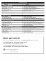
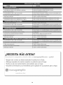
PROBLEM
SOLUTION
Primer bulb wasn't pressed enough
Press primer bulb fully and slowly 10 times
Old or improperly mixed fuel
Drain fuel tank and add fresh fuel mixture
Plugged spark arrestor
Clean or replace spark arrestor
The outside temperature
is above 90 ° F
Pull the starter rope up to 10-15 times
Old or improperly mixed fuel
Drain fuel tank and add fresh fuel mixture
Old or improperly mixed fuel
Drain fuel tank and add fresh fuel mixture
Cultivator tines bound with debris
Stop the unit and clean or remove any debris binding the tines
Plugged spark arrestor
Clean or replace spark arrestor
Old or improperly mixed fuel
Drain fuel tank and add fresh fuel mixture
Air filter is plugged
Replace or clean air filter
Plugged spark arrestor
Clean or replace spark arrestor
9
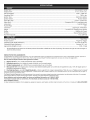
Engine
Type.................................................................................................................................................................
Air-Cooled,
2Cycle
Displacement
...............................................................................................................................................................
31.5cc(1.95cuin.)
IdleSpeedRPM
............................................................................................................................................................
2,600- 3,600rpm
Operating
RPM............................................................................................................................................................
7,800+
rpm
Ignition
Type
................................................................................................................................................................
Electronic
Ignition
ignition
Switch
..............................................................................................................................................................
Rocker
Switch
SparkPlugGap.............................................................................................................................................................
0.025in.(0.635
mm)
SparkPlug...................................................................................................................................................
Champion
RDJ7Y
orequivalent
plug
Lubrication
.................................................................................................................................................................
Fuel/Oil
Mixture
Fuel/Oil
Ratio...............................................................................................................................................................
40:1
Carburetor
..................................................................................................................................................................
Diaphragm,
All-Position
Starter
..........................................................................................................................................................
Incredi-PullStarting Auto Rewind
TM
Muffler .....................................................................................................................................................................................
Baffled with Guard
Throttle ..............................................................................................................................................................................
Fuel Tank Capacity .......................................................................................................................................................................
Manual Spring Return
13 oz. (384 ml)
Drive Shaft Housing ...........................................................................................................................................................................
Throttle Control .......................................................................................................................................................................
Cultivating Path Width (Maximum) .......................................................................................................................................
Cultivating Depth (Maximum) .................................................................................................................................................
Approximate Weight (no fuel) .........................................................................................................................................................
*
Steel Tube
Finger-Tip Trigger
9 inches (22.86 cm)
5 inches (12.7 cm)
26 lb. (12 kg)
All specifications are based on the latest product information available at the time of printing. We reserve the right to make changes at
any time without notice.
REPAIR PROTECTION
AGREEMENTS
Congratulations on making a smart purchase. Your new Craftsman® product is designed and manufactured for years of dependable operation.
products, it may require repair from time to time. That's when having a Repair Protection Agreement can save you money and aggravation.
Here is what the Repair Protection
[]
Expert
service
[]
Unlimited
[]
Product
[]
Discount
preventive
by our 10,000
service
Plan Agreement
professional
and no charge
replacement
of 10% from
maintenance
includes:
repair
specialists
for parts and labor
up to $1500
regular price
checks
if your
But like all
covered
of service
on all covered
product
and related
repairs
can not be fixed
installed
parts not covered
by the agreement;
also,
10% off regular
price of
[]
Fast help by phone - we call it Rapid Resolution
- phone support from a Sears representative.
Think of us as a "talking owner's manual."
Once you purchase the Repair Protection Agreement, a simple phone call is all that it takes for you to schedule service. You can call anytime day or night, or
schedule a service appointment online.
The Repair Protection Agreement is a risk-free purchase. If you cancel for any reason during the product warranty period, we will provide a full refund. Or a prorated
refund anytime after the product warranty period expires. Purchase your Repair Protection Agreement today!
Some limitations and exclusions apply. For prices and additional information call 1 =800=827=6655.
*Coverage in Canada varies on some items. For fuU details call Sears Canada at 1=800=361 =6665.
Sears Installation
Service
For Sears professional installation of home appliances, garage door openers, water heaters, and other major home items, in the U.S.A. or Canada call 1-800-4-MY-HOME ®.
10
Manual
del Operador
MRN
2-Tiempos
MINI CULTIVADORA A GASOLINA
Modelo
No. 316.292640
,, SEGURIDAD
* MONTAJE
* FUNCIONAMIENTO
* MANTENIMIENTO
* LISTADO DE PIEZAS
PRECAUCION: Lea el manual
del operador y siga todas las
advertencias
e instrucciones
de seguridad.
Sears Brands
Management
Corporation,
Visite nuestro
769-06626A P00
Hoffman
Estates,
iL 60179 U.S.A.
sitio web: www.craftsman.com
02/11
PROPOSlCION
65 DE CALIFORNIA
Toda la informaci6n, las ilustraciones y las especificaciones contenidas en
este manual se basan en la informaci6n mas reciente disponible en el
momento de impresi6n del manual. Nos reservamos el derecho de hacer
cambios en cualquier momento sin aviso previo.
LAS EMISIONES DEL MOTOR DE ESTE PRODUCTO CONTIENEN
SUBSTANCIAS QUIMICAS QUE EL ESTADO DE CALiFORNiA
CONOCE COMO CAUSANTES DECANCER, DEFECTOS DE
NACIMIENTO U OTROS DA_IOS REPRODUCTIVOS.
Los simbolos de seguridad se utilizan para Ilamar su atenci6n sobre
posibles peligros. Los sfmbolos de seguridad y sus explicaciones merecen
toda su atenci6n y comprensi6n. Los dmbolos de seguridad no eliminan
ningOnpeligro por si mismos. Las instrucciones o advertencias que ofrecen
no substituyen las medidas adecuadas de prevenci6n de accidentes.
INDICE DE CONTENIDOS
Normas para una operaci6n segura .......................
14
Garantia .............................................
16
Conozca su unidad ....................................
16
Instrucciones de ensamble ..............................
16
Informaci6n del aceite y del combustible
...................
17
Instrucciones de arranque y apagado ......................
17
Instrucciones de operaci6n ..............................
18
Instrucciones de mantenimiento y reparaci6n
...............
19
Limpieza y almacenamiento
.............................
20
Resoluci6n de problemas ...............................
21
Especificaciones
......................................
22
Lista de piezas .......................................
26
Numeros de servicio .........................
Contraportada
SIMBOLO
,_
NOTA:
Le ofrece informaci6n o instrucciones que son esenciales
para la operaci6n o mantenimiento del equipo.
PELIGRO: El no obedecer una advertenciade seguridad puede
conducir a que usted u otras personassufrangraves lesiones.Siga
siemprelas precaucionesde seguridad para reducirel riesgode
incendio,descargaelectricay lesionespersonales.
ADVERTENCIA:
El no seguir una advertencia de seguridad
puede conducir a que usted u otras personas sufran lesiones.
Siga siempre las precauciones de seguridad para reducir el
riesgo de incendio,descarga electrica y lesiones personales.
NOTA:Para los usuariosen tierras forestales de los EE.UU.yen losestados
de California, Maine, Oregon y Washington. Todos losterrenosforestales de
losEE.UU.y el estado de California(C6digos de RecursosPublicos4442y 4443),
Oregony Washington,requierenpot decreto,que ciertos motores de combusti6n
internaque se hagan funcionar en zonas boscosas y/o zonas cubiertas por
pastizales,esten equipados con un parachispas,que sean mantenidos en buen
estado de funcionamiento o que el motor sea construido, este equipado y sea
mantenido para evitar incendios.Consulte los reglamentos pertinentes a esos
requisitos con las autoridades estatales o locales.El incumplimientode esos
requisitospuede responsabilizarleo someterlea laimposici6nde unamulta. Esta
unidadfue equipada en lafAbrica con un parachispas.Si requieresustituci6n,
hay una Pantafla Parachispas disponible, Pieza #753-04926 al contactar el
departamento de servicio.
= IMPORTANTE
PRECAUCION:
El no seguir una advertencia de
seguridad puede conducir a dar_o patrimonial o a que usted
u otras personas sufran lesiones personales. Siga siempre
las precauciones de seguridad para reducir el riesgo de
incendio, descarga electrica y lesiones personales.
Lea el manual del operador y siga todas las advertencias e instrucciones
de seguridad. De no hacerlo, el operador y/o los espectadores pueden
sufrir graves lesiones.
INFORMACION
LEA TODAS LAS INSTRUCCIONES ANTES DE LA OPERACION
• Lea las instrucciones cuidadosamente. Familiaricese con los
controles y el uso adecuado de la unidad.
No opere esta unidad cuando este cansado, enfermo o bajo la
influencia de alcohol, drogas o medicamentos.
Los nitros y los adolescentes menores de 15 argos de edad no deben
usar la unidad. Los adolescentes pueden hacerlo bajo la supervisi6n
de un adulto.
pueden explotar si se encienden.
Tomelassiguientes
precauciones:
ADVERTENCIA:
La gasolina
es muy inflamabley
sus gases
DE SEGURIDAD
=
Almacene el combustible solamente en recipientes diser_ados y
aprobados especificamente para el almacenamiento de dichos
materiales.
Evite crear una fuente de ignici6n para el combustible derramado. No
arranque el motor hasta que se disipen los vapores del combustible.
Pare siempre el motor y deje que se enfrie antes de Ilenar el tanque
de combustible. Nunca quite la tapa del tanque de combustible, ni
agregue combustible, cuando el motor este caliente. Nunca opere la
unidad sin la tapa de combustible bien colocada en su lugar. Afloje
la tapa del tanque de combustible lentamente para aliviar cualquier
presi6n que haya en el tanque.
Agregue el combustible en un Area exterior bien ventilada, donde no
haya chispas ni llamas. Quite lentamente la tapa de combustible
s61o despues de haber parado el motor. No fume mientras este
Ilenando de combustible o mezclandolo. Limpie de la unidad
inmediatamente cualquier combustible derramado. Seque siempre
la unidad antes de usarla.
Todos los dispositivos de protecci6n y los accesorios de seguridad
deben estar instalados adecuadamente antes de operar la unidad.
Inspeccione la unidad antes de usarla. Reemplace las piezas
dar_adas. Verifique si hay fugas de combustible. AsegOrese de que
todos los fijadores esten en su lugar y asegurados. Reemplace las
piezas que esten agrietadas, astilladas o dar_adas en cualquier
forma. No opere la unidad con piezas sueltas o dar_adas.
Inspeccione cuidadosamente el Area antes de operar la unidad.
Elimine todos los escombros y los objetos duros o filosos tales como
cristal, alambre, etc.
Este consciente del riesgo de lesi6n en la cabeza, las manos y los pies.
No permita niSos, espectadores ni mascotas en el _.rea. Los niSos,
los espectadores y las mascotas deben estar fuera de un radio de 50
pies (15 m) como minimo; de todas formas los espectadores
correrb.n el riesgo de ser golpeados pot objetos lanzados pot la
unidad. Se debe exhortar a los espectadores a que usen protecci6n
para los ojos. Si se le acerca alguien apague la unidad de inmediato.
Optima el control del estrangulador y compruebe que regresa
autom_.ticamente a la posici6n de marcha en vacio. Haga todos los
ajustes o reparaciones antes de usar la unidad.
ADVERTENCIAS DE SEGURIDAD A GASOLINA
--
ALERTA
DE SEGURIDAD:
peligro,advertencia
o
precauci6n. Debe
prestar atenci6n paraIndica
evitarsufrir
graves lesiones
personales. Puede ser utilizadojunto con otros simbolos o figuras.
PARAC H ISPAS
_
SIGNIFICADO
Mueva siempre la unida a 30 pies (9.1 m) como minimo de la fuente y
sitio de combustible antes de arrancar el motor. No fume ni permita
chispas ni llamas expuestas cerca del Area mientras este agregando
combustible u operando la unidad.
DURANTE LA OPERACION
= Nunca arranque ni opere la unidad dentro de un cuarto o edificio
cerrado. Respirar los vapores del escape puede ser fatal. Opere
esta unidad solamente en un Area exterior bien ventilada.
i
12
Use gafas protectoras que cumplan con la norma Z87.1 de ANSI y
tengan la marca que Io indica. Use protecci6n para la oreja/audici6n
cuando opere esta unidad. Use mascara facial o para polvo si la
operaci6n produce mucho polvo.
Use pantalones largos fuertes, botas, guantes y camisa de mangas
largas. No use ropa holgada, joyas, pantalones cortos, sandalias, nieste
descalzo. Asegurese el cabello por encima del nivel de los hombros.
• Estaunidad
tieneunembrague.
LaspOas
permanece
estacionario
Usesolamente
piezas
yaccesorios
dereemplazo
delfabricante
del
cuando
launidad
estaenmarcha
envacio.
SinoIohace,
haga
equipo
original
paraestaunidad.Estos
estan
disponibles
ensu
ajustar
launidad
poruntecnico
deSears
uotrotecnico
deservicio
proveedor
deservicio
autorizado.
Elusodecualquier
pieza
o
calificado.
accesorio
noautorizado
podria
causar
lesiones
graves
alusuario,
o
da_os
a launidad,
yanular
sugarantia.
Antesdearrancar
launidad
asegOrese
dequelaspOas
noesteen
contacto
connada.
Mantenga
launidad
limpia
devegetaci6n
yotrosmateriales.
Pudieran
quedar
obstruidas
entrelaspOas
y elprotector.
Uselaunidad
solamente
dediaoconbuena
luzartificial.
Para
r
educir
elpeligro
deincendio
reemplace
unsilenciador
y
Evitearranques
accidentales.
Este
enlaposici6n
dearranque
cada
amortiguador
dechispas
defectuoso.
Mantenga
elmotor
yelsilenciador
vezquehalelacuerda
dearranque.
Eloperador
ylaunidad
deben
hojas,
exceso
degrasa
oacumulaci6n
decarb6n.
estarenunaposici6n
estable
alarrancar.
Consulte
lasInstrucciones libredehierba,
DESPUES DE USARLA
deArranque/Parada.
Uselaherramienta
correcta.
Useestaherramienta
solamente
parael
Limpie las pQas con un limpiador casero para eliminar la acumulaci6n
prop6sito
paraelcualfuedise_ada.
de resina. Aceite las pOas con aceite de maquina para evitar la
corrosi6n.
Tenga
mucho
cuidado
cuando
invierta
omueva
launidad
hacia
usted.
OTROS
AVISOS DE SEGURIDAD
Noseestire
demasiado.
Mantenga
siempre
labasedeapoyo
y
•
Nunca
almacene una unidad con combustible dentro de un edificio en
equilibrio
adecuados.
Tenga
mucho
cuidado
cuando
trabaje
en
pendientes
marcadas
oinclinadas.
el cual los vapores puedan Ilegar a una llama expuesta o una chispa.
Sostenga
siempre
launidad
conambas
manos
cuando
laopere.
Deje que el motor se enfrie antes de almacenarlo o transportarlo.
Mantenga
unagarre
firmesobre
ambas
manijas.
AsegOrese de fijar bien la unidad mientras la transporta.
Mantenga
lasmanos,
lacaray lospiesalejados
detodaslaspartes
Almacene la unidad en un Area seca y cerrada, o en un lugar alto para
enmovimiento.
Notoquenitratedepararlosdientes
cuando
esten
evitar uso no autorizado o da_os. Mantengala alejada del alcance de
los ni_os.
girando.
Notoqueelmotoro elsilenciador.
Estas
piezas
estan
muycalientes
Nunca rocie ni chorree la unidad con agua ni ningOn otto liquido.
durante
laoperaci6n,
incluso
despues
dequeseapaga
launidad.
Mantenga las manijas secas, limpias y libres de escombros. Limpiela
despues de usarla, vea las instrucciones de Limpieza y
Noopere
elmotoramasvelocidad
delanecesaria
paracultivo.
No
Almacenamiento.
hagafuncionar
elmotoraaltavelocidad
cuando
noestecultivo.
Conserve estas instrucciones. ConsOltelas con frecuencia y Oselas
Pare
siempre
elmotorcuando
dejedecultivo
o cuando
este
para instruir a otros usuarios. Si le presta esta unidad a alguien,
caminando
deunlugardecultivo
haciaotto.
prestele tambien estas instrucciones.
Sigolpea
oseenreda
conunobjeto
extrano,
pare
elmotor
inmediatamente
yverifique
sihahabido
algOn
dano.NoIoopere
antes
dereparar
eldano.Noopere
launidad
conpiezas
sueltas
odanadas.
CONSERVE ESTAS INSTRUCCIONES
Parelaunidad,
apague
elmotor
ydesconecte
labujiapara
mantenimiento
oreparaci6n.
,, SIMBOLOS
DE SEGURIDAD
E INTERNACIONALES
,,
Este manual del operador describe los simbolos y figuras de seguridad e internacionales que pueden aparecer en este producto. Lea el
manual del operador para obtener informaci6n completa acerca de la seguridad, ensamble, operaci6n y mantenimiento y reparaci6n.
SIMBOLO
SIGNIFICADO
SIMBOLO
*'_7,_.d_
Indica peligro, advertencia 0 Piecauci6n: Puede Set
=SIMBOLO DE ALERTA DE SEGURIDAD
utilizado junto con otros simbolos 0 figuras:
//_/-_._
//"_
-_-'/" "_
,Lea
ADVERTENCIA.
el manua! del 0perador
LEA EL yMANUAL
siga todaSDEL
las adve_enCias
e instrucci0nes de seguridadi De no hacedo, el operador
y/o los espectadores pueden sufrir graves lesione&
I
ii
i
i
i
i
Y LA CUCHILLA
ROTATIVA PUEDEN No
CAUSAR
GRAVES
ADVERTENCIA:
opere esta
unidad LESIONES
si la
protecci6n plastica de linea no estA colocada en su lugar.
o MANTENGA
ALEJADOS A LOS ESPECTADORES
Mantenga a todos los espectadores,
en especial a niSos y animales dom6sticos a por Io menos
50 pies (15 m) del Area de corte.
L,"_';"_'_,._
' ADVERTENOIA:
OCULAR Y AUDITIVA
• ADVERTENCIA
ADVERTENCIA:
Los objet0s arrojad0s por la unidad y
el ruido fuerte pueden causar graves !esiones ocularesy
p@didaauditiva. Uti!ice protecci6n ocular que cumpla Conlas
normas ANS! Z87.! y prot_ci6n auditiva cuando opere esta
unidad. Use una careta completa cuando la necesite.
DE CALIENTE
NO toque un silenciador ni un cilindro caliente. Puede
quemarse. Estas partes se calientan mucho con el
uso. Luego de apagarse permanecen calientes
durante un corto tiempo.
J,COMBUSTIBLEPLOMO
i_
" LOS OBJETOS DESPEDIDOS
.[ Mant_ngase a ejado de accesor o de corte g rator o.
OPERADOR
, USE PROTECCION
SIGNIFICADO
_1
[,ses,er p ecom0us,
0uovoys0
p,omo
e,,mp,o
_i _ _ _L_I
_i _i _ii_ii_i
_iIZZZZZZZZZZZZZZZZZZZI
oDE
PARADo
CONTROL
ENCEND¥APAGADO
DO
A,.i
f_
13
.[ acerca del tipo correcto de aceite.
Oprima la bombilla del cebador completa y
I, BOMBILLA
DEL10CEBADOR
lentamente, de
veces
i_l
APAGADO
• INDICADOR DE ACEITE
Consulte el manual del operador para obtener informaci6n
I, CULTIVADORES PAPA JARDINES - LAS PUAS
GIP.ATORIAS PUEDEN
CAUSAR
GRAVES
LESIONES
ADVERTENCIA:
Apague
el motor
y espere
que las
p0as se detengan antes de instalar o sacar las pQas,o
" antes de realizar la limpieza o todo tipo de mantenimiento.
Mantenga las manos y los pies lejos de las pOas giratorias.
GARANTJA
TOTAL
POR 2 AI_IOS, DE CRAFTSMAN
Este producto se garantiza DURANTE 2 A_4OS a partir de la fecha de compra, contra defectos en el material o en la mano de obra. El producto defectuoso
ser& reparado sin ningOn costo o serA remplazado gratuitamente si no puede ser reparado.
Para conocer los detalles sobre la cobertura de la garantia para que sea reparado o reemplazado,
visite el sitio web: www.craftsman.com
Esta garantfa
cubre SOLAMENTE
defectos
en el material
o rnano de obra. La cobertura
de la garantia
NO incluye:
• Articulos consumibles que se desgasten debido al uso normal dentro del periodo de la garantia, tales como cuchillas, dientes o correas.
Da_os que ocurran al producto como resultado de intentos de modificaci6n o reparaci6n por parte del usuario, o que sean causados por accesorios del producto.
Reparaciones necesarias debidas a accidente o falla en el funcionamiento,
o por no mantener el producto de acuerdo con todas las instrucciones
El mantenimiento preventivo, o reparaciones necesarias debido a mezcla incorrecta de combustible, o a combustible viejo o contaminado.
Esta garantia es nula si este producto se utiliza alguna vez durante la prestaci6n
Esta garantia le otorga a usted derechos
legales especificos,
de servicios de tipo comercial
provistas.
o si se le alquila a otra persona.
y usted puede ademAs poseer otros derechos, los cuales varian de un estado a otro.
Sears Brands Management
Corporation,
Hoffman Estates, IL 60179
APLICACIONES
Control
de encendido
• Cultivo de cesped y tierra ligera a mediana
Cultivo en jardines, alrededor de arboles, etc.
y apagado
Mango
Controlidel
regulador
Mango dela cuerda
de arranque
Tap6n del
combustible
Mango del
tubo del eje
Protecci6n
Perilla del
de las peas
manubrio
Peas
Bornbilla de
cebado
Cubierta del
silenciador
/
filtro de aire
Ensarnble de soporte
de la rueda
Caja de
engranajes
ENSAMBLE
Bujfa de
encendido
DE LA UNIDAD
COLOCACION
Su cultivador para jardines ha sido completamente ensamblado. El
manubrio debera colocarse en la posiciSn adecuada antes de la operacbn.
NOTA: Antes de su operacbn, es posible que deba cambiar la posiciSn
de la altura de la rueda. LeaAjuste de la Profundidad de las Puas.
Desembale con cuidado el contenido y verifique que no haya piezas
dadadas.
1.
2.
Silenciador
DEL MANUBRIO
Afloje las dos perillas del lado interior del manubrio (Fig. 1).
Con la unidad en posici6n vertical, gire el manubrio hacia arriba
hasta la posici6n de operaci6n (Fig. 1).
NOTA: Tenga cuidado de no pellizcar el cable del regulador o los
cables del interruptor cuando coloque el manubrio.
14
3. Ajustelasperillas
para
asegurar
elmanubrio
en
sulugar.
NOTA:Noajustelasperillas
demasiado.
4. Vuelva
aajustar
elcable
del
delregulador
y loscablesPerilla
manubrio
delinterruptor
demodo
quequeden
parejos
y
estirados
contrael
ensamble
delmanubrio.
Estoevitara
quese
aprisionen
o se
desbarben
durante
la
Perno
operaci6n
normal.
INSTALACION
DEL
INSTRUCCIONES PARA MEZCLAR EL ACEITE Y EL COMBUSTIBLE
,7
El combustible viejo o mal mezclado son los motivos principales del mal
funcionamiento de la unidad. AsegQrese de usar combustible nuevo,
limpio y sin plomo. Siga las instrucciones en detalle para mezclar
correctamente el aceite y el combustible.
Definici6n de los combustibles
de mezcla
Los combustibles actuales con frecuencia son una mezcla de gasolina y
oxigenantes como por ejemplo etanol, metanol o MTBE (eter).El combustible
mezclado con alcohol absorbe agua. Unacantidad tan pequeSa como el 1%
de agua en el combustible puede causar la separaci6n del combustible y el
aceite. Forma acidos cuando esta almacenado. Cuando use combustible
mezclado con alcohol, use combustible nuevo (de menos de 60 dias).
Uso de combustibles
de mezcla
Fig, 1
Perilla del
manubrio
I Arandela /
Si usted opta pot usar un combustible de mezcla o si su uso es
inevitable, tome las precauciones recomendadas.
• Use siempre una mezcla fresca de combustible segQn Io indica su
manual del operador.
• Agite siempre la mezcla de combustible antes de cargado en la unidad.
• Drene el tanque y haga funcionar el motor en seco antes de
guardar la unidad.
Uso de aditivos en el combustible
ENSAMBLE DE SOPORTE
DE LA RUEDA
Si el montaje de soporte de la
rueda no esta instalado, o si
usted necesita siempre
quitarlo o reinstalar, siga las
instrucciones que
sobrevienen.
1.
2.
3.
Manubrio
Fig. 2
La botella de aceite de 2 ciclos que vino con su unidad contiene un aditivo
en el combustible que ayudara a inhibirla corrosi6n y a reducir la formaci6n
de dep6sitos de goma. Se recomienda que use s61oel aceite de 2 ciclos
con esta unidad. Si es inevitable,use un buen aceite de 2 ciclos elaborado
para motores enfriados por airejunto con un aditivo para el combustible
como por ejemplo el estabilizador de gasolina STA-BIL® o similar.Agregue
23 mL (0,8onzas) de aditivo de combustible por gal6n de combustible de
acuerdo con las instruccionesdel envase. NUNCA agregue aditivos
directamente en eltanque de combustible de la unidad.
Con la unidad sobre su lado, coloque el ensamble de soporte de
la rueda en el lado inferior de la protecci6n de las pQas (Fig. 3).
Instale un perno de carro a traves de cada uno de los orificios
ranurados del soporte de la rueda y en la protecci6n de las pQas.
Instale una arandela de seguridad y una tuerca de mariposa en
cada uno de los pernos de la parte superior de la protecci6n de
las pQas (Fig. 3).
4.
Verifique que el hombro cuadrado de los pernos haya atravesado
los orificios ranurados del
soporte de la rueda. Ajuste
las tuercas de mariposa
(Fig. 4).
Protecci6n
NOTA: No ajuste demasiado
de las peas
las tuercas de
mariposa. Aflojar las
tuercas de mariposa
Tuerca de mariposa y
permite ajustar el
arandela de seguridad
peso de la rueda.
Ensamble del soporte de la rueda
AJUSTE DE LA
Fig. 3
PROFUNDIDAD
El ajuste de las pQas podra
variar de acuerdo al tipo de
tierra que cultiva y el modo en
que sera usado. En general,
se recomienda ajustar las
pQas para abrir la tierra de 4 a
6 pulgadas para la mayoria de
los jardines. Ajuste las pQas
de este modo:
1.
2.
3.
4.
Pare el motory
desconecte el cable de la
bujia de encendido.
',
_
Mezcle bien la proporci6n correcta de aceite para motor de 2 ciclos y
gasolina sin plomo en una lata de combustible por separado. Use una
proporci6n de 40:1 de combustible y aceite. No los mezcle directamente en
eltanque de combustible de la unidad. Consulte las proporciones
especificas de mezcla de gasolina y aceite en latabla siguiente.
NOTA: 3,8 litros (un gal6n) de
gasolina sin plomo
mezclada con una
botella de 95 mL (3,2
onzas) de aceite de 2
ciclos es una
proporci6n de 40:1 de
GASOLINA SiN
ACEITE DE 2
combustible y aceite.
PLOMO
ClCLOS
NOTA: Elimine la mezcla vieja
3,8 LITROS
95 rnL
de aceite y
(1 GALON de
(3,20NZAS
combustible de
EE.UU.)
FLUIDAS)
acuerdo con los
1 MTRO
25 mL
reglamentos federales,
estatales y locales.
PROPOROION DE LA MEZCLA = 40:1
Arriba
Abajo
Fig. 4
ADVERTENClA:
La gasolina es muy inflamable. Los
gases pueden explotar si se encienden. Apague siempre el
motor y espere que se enfrie antes de cargar el tanque de
combustible. No fume mientras Ilena el tanque. Mantenga
las chispas y las llamas lejos del Area.
Afloje (no retire) las dos tuercas de mariposa de la protecci6n
de las pQas (Fig. 5).
Deslice el ensamble del soporte de la rueda hacia abajo para
Iograr una penetraci6n mas superficial, y hacia arriba para
Iograr una penetraci6n mas profunda.
5.
Una vez que las pQas se encuentran en la posici6n deseada,
ajuste las tuercas de mariposa, verificando que los pernos de
carro estan bien sentados a traves del soporte.
Si la profundidad de las pQas no es correcta, repita los pasos 2 a 4.
6.
Vuelva a conectar el cable de la bujia de encendido y continQe
y con la mayor fiabilidad, preste mucha atenci6n a las
instruccionesde mezcla de aceite y combustible del envase de
aceite
de 2 ciclos. El uso
deque
combustible
mezclado
en forma
RECAUCION:
Para
el motor funcione
correctamente
incorrectapuede daSar seriamente el motor.
,_
SU USO.
_
15
ADVERTENCIA:
Saque
latapadel
delcombustible.
combustible No
lentamente
para evitar lesionarse con
el rociado
opere
nunca la unidad sin la tapa del combustible flrmemente colocada
en su lugar.
limpia y bien ventilada. Limpie de inmediato todo combustible
que se haya derramado. Evite crear una fuente de encendido con
el combustible
derramado.
No arranque
el motor
que se
DVERTENCIA:
Cargue
el combustible
en hasta
un Areaexterior
hayan evaporado los gases del combustible.
LLENADO DEL TANQUE DE
COMBUSTIBLE
AsegQrese de que la
cultivadora este en posici6n
horizontal al Ilenar o agregar
combustible al tanque (Fig. 5).
SL. El motor no arranca, regrese al paso 3.
NOTA: Si la unidad estb` caliente y no Iogra arrancar despues de
halar 3 veces el cord6n de arranque, apriete el control del
obturador y hale el cord6n de arranque hasta que la unidad
arranque.
INSTRUCCIONES DE APAGADO
1.
Saque la mano del control del regulador. Deje enfriar el motor
en marcha en vacio.
2.
Coloque el control de encendido
APAGADO (O) (Fig. 6).
Fig. 5
CONSEJOS
y apagado en posici6n de
PARA LA OPERACION
ADVERTENCIA:
unidad
s61o en de
un mon6xido
Area
exterior bien ventilada.Use
Losesta
gases
de escape
de carbono pueden ser letales en un Area cerrada.
ADVERTENCIA:
Evitelos arranquesaccidentales. Col6quese
en posicbn de iniciocuando tire de lacuerda de arranque (Fig.5). El
operador y launidad deben estar en una posici6n estable alarrancar
launidad para evitargraves lesionespersonales.
INSTRUCCIONES
1.
j_
1.
DE ARRANQUE
Mezcle la gasolina con el
aceite. Vea las
Instrucciones para
Mezclar el Aceite y el
Combustible.
Llene el tanque de
combustible con la
mezcla de
combustible/aceite,
NOTA: No hay necesidad de
_j_
2.
3.
4.
Apagado (O)
Control del
regulador
Encendido (I)
girar la unidad.
Fig. 6
Encendido/de parada el
control (Fig. 6) estb`en la_
Bulbo cebador
posici6n de trabajo
_-/d_.
../__
J
siempre (I).
_
"_J__._h
J
Oprima completamente el
_,
f_ _J_
cebador y sueltelo 10 veces. "\ (f / f _f_
Hb`galolentamente. Se
_. / _//_'_
\\
deber& ver un poco de
\
_/_,_/"
)/
ol]
combustibleenelcebadory
\",,,
,_, ( _'_l
I/
en lastuberias de
"_"J -_.\_
It S_)
alimentaci6n de combustible
\__
(Fig. 7).Si no puede ver el
Fig. 7
combustible en elcebador,
Posici6n de
oprfmalo y sueltelo tantas
Arranque
veces como sea necesario
hasta que vea combustible
_I-P/,_LAgH"
en el mismo.
\
Agb`chese en la posici6n
de salida (Fig. 4). No
exprima la vb,lvula
reguladora, tiran de la
cuerda del arrancador con
Control del
un movimiento controlado
regulador
hasta que la unidad
Fig. 8
comience. Espere y permita
que la unidad este desocupada pot 60 segundos.
el riesgo de lesiones cuando opere esta unidad. No use
ropa holgada ni alhajas. Use protecci6n ocular y auditiva.
Use pantalones largosVista
y gruesos,
y guantes.
use
_ADVERTENClA:
en formabotas
adecuada
para No
reducir
pantalones cortos, sandalias ni trabaje descalzo.
Transporte el cultivador hacia el b,reade trabajo antes de
arrancar el motor. Puede transportar el cultivador empujb,ndolo
sobre ruedas.
ADVERTENCIA:
nunca
levante ni transporte
Para evitar
la unidad
graves
conlesiones
el motor personales,
en marcha.
2.
3.
Arranque la unidad siguiendo las instrucciones
Con el motor en marcha y las pOas
sin tocar el suelo, optima el control
del regulador para aumentar la
velocidad del motor.
4.
Mientras sostiene ambos mangos
del manubrio, baje lentamente el
cultivador hasta que las pOas hacen
contacto con el suelo (Fig. 9).
A medida que comienza la actividad
de cultivo, mueva el cultivador hacia
atrb,s de modo que las pOas puedan
penetrar en la tierra.
Una vez que se ha abierto la tierra,
continOe a un ritmo moderado
hasta que conozca bien los
controles y el manejo del cultivador.
Fig. 9
Para mejorar la profundidad de cultivo, hale hacia atrb,s la unidad a
medida que avance para que penetren mb,s las pQas en la tierra.
5.
6.
7.
_
de arranque.
tenga mucho cuidado cuando invierta o gire la unidad hacia
DVERTENClA:
Para evitar graves lesiones personales,
usted.
8.
Si las pQas estb,n cavando a una profundidad excesiva o
insuficiente, ajuste las pOas de acuerdo a la secci6n Ajuste de
la profundidad de las pOas.
TRANSPORTE DE LA UNIDAD
Exprima y celebre el control de vb,lvula reguladora para que los 30 a
60 segundos adicionales permitan que la unidad caliente.
NOTA: La unidad usa INCREDI=PULL TM Io cual reduce
considerablemente el esfuerzo requerido para arrancar el
motor. Debe halar el cord6n de arranque Io suficiente para
oir que el motor trata de arrancar. No es necesario halar el
cord6n con energia: no hay fuerte resistencia al halar.
Tenga en cuenta que este metodo de arranque es muy
diferente (y mucho mb,s fb,cil) del que usted pudiera estar
acostumbrado a usar.
5.
16
apague siempre el motor cuando demote la operaci6n o
j_
_ADVERTENClA:
evitar
graves
lesiones
personales,
mientras transporta laPara
unidad
entre
b,reasde
trabajo.
1.
2.
Apague el motor.
Deslice el ensambb del soporte de la rueda totaimente hacia abajo.
3.
4.
5.
incline la unidad hacia atrb,shasta que las pOas desmabzan la tierra.
Empuje o Ileve la unidad hasta el pr6ximo lugar que deba cultivar.
Si necesita trasladar la unidad largas distancias, use el agarre
de transporte.
PROGRAMA DE MANTENIMIENTO
4.
nunca realice manteni-miento ni reparacionescon la unidad
funcionando. Realice siempre el mantenimiento y las reparaciones
con
la unidad Na. Desconecte
el cable
de lapersonales
bujia de encendido
DVERTENClA:
Para evitar
lesiones
graves,
para cerciorarse de que la unidad no arrancar&
_
NOTA:
Estos procedimientos requeridos para el mantenimiento deben ser
realizados con la frecuencia indicada en latabla. Deben ser incluidos como
parte de toda puesta a punto de cada temporada.
NOTA: Es posible que algunos procedimientos de mantenimiento
requieran herramientas o habilidades especiales. Si no
est,, seguro sobre estos procedimientos, Ileve la unidad a
Sears o a otro proveedor de servicio calificado. Para mas
informaci6n, Ilame al 1-800-4-MY-HOME ®.
NOTA: El mantenimiento, el reemplazo o la reparaci6n de los
dispositivos y del sistema de control de emisiones puede ser
realizado por Sears o por otra agencia de servicio calificada.
Para mas informaci6n, Ilame al 1-800-4-MY-HOME ®.
A fin de garantizar el rendimiento mAximo de su motor, pudiera ser
necesaria la inspecci6n de la lumbrera de escape del motor despues de
50 horas de operaci6n. Si usted nota perdida de RPM, un rendimiento
insuficiente o una falta general de aceleraci6n, pudiera requerirse este
servicio. Si usted considera que su motor necesita esta inspecci6n,
consulte con Sears u otra agencia de servicio calificada. Para mas
informaci6n, flame al 1=800=4=MY-HOME®. NO trate de realizareste
proceso usted mismo ya que pudiera da_ar el motor como resultado de
contaminantes presentes en el proceso de limpieza de la lumbrera.
FRECUENCIA
MANTENIMIENTO
REQUERIDO
5.
Llene el tanque de combustible
con la mezcla correcta de aceite
y combustible
p. 16
Cada 10 horas
Limpie y vuelva a aceitar el
filtro de aire
p. 17
Cada 25 horas
Examine el parachispas y limpielo
Inspeccione la condici6n y la
separaci6n de la bujia de
encendido
p. 18
p. 18
Cada 50 horas
Inspeccione si la lumbrera de
escape y la rejilla del
parachispas est_.n tupidas u
obstruidas para garantizar los
niveles m&ximos de rendimiento
p. 18
_
Y REPOSICION
Saque los cuatro (4)
tornillos que sostienen la
cubierta del silenciador /
filtro de aire (Fig. 12). Use
un destornillador de
vb,stago piano o de broca
Torx N° T20.
Quite la tapa del motor al
empujarla hacia arriba y
halarla hacia atras. No la
fuerce.
Limpieza del Filtro de Aire
No mantener debidamente el
filtro de aire puede resultar en
funcionamiento inadecuado o
puede causar dado
permanente a en el motor.
DE LAS PUAS
1.
Coloque el control de
encendido y apagado en
la posici6n de APAGADO
(O} y desconecte el cable
de la bujia de encendido.
Diente "A" _____,.(/_/
--_.
NOTA: Puede ser necesario
Frente del cultivador
Pin del tecleo
colocar la cultivadora
Fig. 10
en posici6n horizontal
Bujes en la parte posterior (no se muestra)
sobre una superficie
plana con la manija
superior tocando el
suelo
3.
apague siempre su recortador y espere que se enfrie antes
Para tipo
evitardegraves
lesiones personales,
deDVERTENClA:
limpiarlo o realizar todo
mantenimiento.
Tornillos
Fig. 12
t
Fig. 13
2.
Las 4 pOas deben cambiarse al mismo tiempo debido a que se
desgastaran en forma pareja
con el uso normal. Trabaje en
un lado por vez.
2.
Usando las Figuras 10 y 11 como referencia, deslice los nuevos
dientes con los cubos hacia afuera.
La condici6n del filtro de aire es
importante para la operaci6n de
la unidad. Un filtro de aire sucio
limitara el flujo de aire y
cambiara la mezcla de
TorniUos,
combustible y aire en el
carburador. Esto con frecuencia
se confunde con un carburador
mal ajustado. Verifique la
condici6n del filtro de aire antes
de ajustar el tornillo de marcha
lenta. Consulte Mantenimiento
del Filtro de Aire.
Remoci6n de la cubierta del
silenciador/filtro
de aire
1.
REMOCION
Si se fija con atenci6n, puede vet una ligera curvatura en
las puntas de los dientes. Estas curvas deberan apuntar
hacia el frente del cultivador cuando se instalan los dientes.
La Figura 11 muestra la curva de cada diente.
Los dientes tienen estampadas "A" o "B." El orden de los
dientes debera ser "B, A, B, A" de izquierda a derecha al estar
de frente a la parte delantera del cultivador.
6. Asegure los nuevos dientes al arbol con chavetas de trinquete.
MANTENIMIENTO DEL FILTRO DE AIRE
CONSULTE
Antes de
arrancar el motor
Cuando est& reinstalando dientes, distribuya los dientes y
comparelos con los que aparecen en la Figura 11. Note las
caracteristicas de cada diente: su cubo, curvatura y letra ("A"o "B").
Esto ayudara a garantizar que est& colocando los dientes correctos
en el orden correcto.
Saque las presillas del
pasador de la horquilla y
los pasadores de la
horquilla (Fig. 11).
1.
Saque la cubierta del
silenciador / filtro de aire.
Lea la secci6n de
Remoci6n e Instalaci6n
de la cubierta del
silenciador / filtro de aire.
2.
Gire la tapay ubique el
filtro de aire adentro.
Saque el filtro de aire de
adentro de la tapa del
filtro de aire / silenciador
(Fig. 13).
Lave el filtro con agua y
detergente (Fig. 14).
Enjuague bien el filtro.
Escurra el exceso de
agua. Dejelo secar por
completo.
3.
Limpie y aceite el eje.
Fig. 11
Fig. 14
Fig. 15
Fig. 16
17
4.
5.
Aplique suficiente aceite limpio SAE 30 para recubrir
ligeramente el filtro (Fig. 15).
Apriete el filtro para esparcir y retirar el exceso de aceite (Fig. 16).
Cambie el filtro de aire dentro de la tapa del filtro de aire /
silenciador (Fig. 12).
NOTA" Si opera la unidad sin el filtro de aire y el ensamble de la
cubierta del silenciador / filtro de aire, su garantia quedara
AN ULADA.
Reinstalaci6n de la cubierta del silenciador/filtro
de aire
3.
Cambie las bujias que
esten rajadas, sucias o
deterioradas. Fije la
separaci6n de aire a
0,635 mm (0,025
pulgadas) utilizando un
calibrador (Fig. 18).
4.
Instale una con
bujialade
(0,635 mm)
t
encendido
separaci6n correcta en la
cabeza del cilindro.
Fig. 18
Ajuste girando la Ilave de casquillo de 5/8 pulg. en sentido
horario hasta que este ajustada sin huelgo.
6.
1.
Coloque la cubierta del silenciador / filtro de aire sobre la parte
posterior del carburador y del silenciador. Alinee los orificios de
los tornillos.
Inserte los cuatro (4) tornillos en los orificios de la
cubierta del silenciador / filtro de aire (Fig. 13) y ajQstelos. No
los ajuste demasiado.
MANTENIMIENTO DEL PARACHISPAS
0,025 pulg.
1
2.
_[
Si usa una Ilave de torsi6n, ajuste a:
12,3-13,5 N,m (110-120 pulg.olibras).
TRANSPORTE
NOTA: El flujo de las emisiones puede ser en una direcci6n solamente:
APARTANDOSEdel motor. Preste mucha atenci6n a c6mo se
ensambla el silenciador, de modo que Io pueda volver a armar
exactamente como estA. El no hacerlo ad da_arA a la unidad y
pudiera causar lesiones personales graves.
1.
2.
3.
Con un destornillador de punta plana, levante cuidadosamente
haciendo palanca la rejilla del parachispas, sacandola del
interior de la cubierta del parachispas.
5.
Limpie la rejila del parachispas con un cepillo de cerdas metalicas.
Cambiela si esta da_ada o si no la puede limpiar completamente.
6.
Reinstale la rejilla del parachispas, ajustandola en forma ce_ida
de nuevo en la cubierta del parachispas.
7.
Reinstale las dos lengQetas de la cubierta en las dos ranuras y
cierre la cubierta del parachispas con un golpe rapido.
Vuelva a colocar el tornillo que quit6 en el Paso 2 y aprietele
firmemente.
8.
I_
Ajuste la tapa del combustible antes del transporte.
Asegure la unidad durante su transporte.
LIMPIEZA
_L_
= No guarde nunca la unidad con combustible en el tanque donde
los vapores puedan Ilegar a una llama o chispa.
Espere que el motor se enfrie antes de guardar la unidad.
Guarde la unidad bajo Ilave para prevenir el uso por
personas no autorizadas y su dado.
Guarde la unidad en un Area seca y bien ventilada.
Guarde la unidad fuera del alcance de los nidos.
ALMACENAMIENTO
PROLONGADO
Si planea guardar la unidad durante un largo periodo de tiempo,
siga el siguiente procedimiento para su almacenamiento.
1. Drene todo el combustible del tanque de combustible en un
recipiente que contenga la misma mezcla de combustible de 2
ciclos. No use combustible que haya permanecido guardado
durante mas de 60 dias. Deseche la mezcla vieja de
combustible y aceite de acuerdo alas regulaciones federales,
estatales y locales.
2. Arranque el motor y dejelo funcionar hasta que se ahogue. Esto
asegura que todo el combustible ha sido drenado del
carburador.
9.
Reinstale la tapa del filtro de aire / silenciador.
AJUSTE DEL CARBURADOR
3.
Espere que el motor se enfrie. Quitele la bujia y eche 5 gotas de
cualquier aceite de motor de 2 tiempos de alta calidad en el
cilindro. Tire de la cuerda de arranque lentamente para esparcir
el aceite. Vuelva a instalar la bujia de encendido.
NOTA: Saque la bujia de encendido y drene todo el aceite del
cilindro antes de intentar arrancar el recortador despues de
su almacenamiento.
NOTA: Los ajustes realizados sin cuidado pueden danar seriamente su
unidad. Contacte una Quemaduras u otro comerciante
calificado del servicio para hacer los ajustes de carburador.
Llame 1-800-4-MY-HOME ® para mAs informaci6n.
CAMBIO DE LA BUJIA DE ENCENDIDO
Use una bujia de encendido Champion RDJ7Y (o similar). La
separaci6n correcta es de 0,635 mm (0,025 pulgadas). Retire la
bujia luego de cada 25 horas de operaci6n e inspeccione su estado.
Apague el motor y espere que se enfrie. Tome el alambre de la
bujia con firmeza y saquelo de la bujia de encendido.
2.
Limpie alrededor de la bujia de encendido. Saque la bujia de
encendido de la cabeza del cilindro girando una Ilave de
casquillo de 5/8 de pulgada en sentido antihorario.
apague siempre su recortador y espere que se enfrie antes
Para evitartipo
graves
lesiones personales,
deDVERTENClA:
limpiarlo o realizar cualquier
de mantenimiento.
Use un cepillo pequer_o para limpiar la parte exterior de la unidad.
No use detergentes fuertes. Los limpiadores domesticos que
contienen aceites aromaticos como pino y lim6n, y con solventes
como el queroseno pueden dar_ar el bastidor de plAstico y la
manija. Seque toda la humedad con un patio suave.
ALMACENAMIENTO
parachispas no se aprieta fijamente se puede caer y causarle
I ADVERTENOIA:
si el cap6
del parachispas
Y pantalla de' i
dano a la unidad y posibles
lesiones
personales graves.
1.
No ajuste demasiado.
• Espere que el motor se enfrie antes de su transporte.
• Drene el combustible de la unidad.
Quite el filtro de aire / tapa del silenciador. Ver Remoci6n de la
Tapa del Filtro /
Silenciador.
Cap6 del parachispas
Motor
Localice el silenciador,
pero no Io quite. Busque
el tornillo en la parte
inferior del silenciador
(Fig. 17). Quite el tornillo
usando una Ilave torx No.
20 o un destornillador
piano.
' L:nn_'_j°t/'a$pa ra-c_'spas Si,en/ador
Levante cuidadosamente
Fig. 17
haciendo palanca el lado
izquierdo de la cubierta del parachispas. Dos lengQetas actQan
como bisagras en el lado derecho de la cubierta. Abra con un
golpe rapido la cubierta del parachispas, como si fuera una
puerta, y despues hale las lengQetas para sacarlas de las
ranuras del silenciador.
4.
raspe ni limpie los electrodos. El motor podria da5arse si
ADVERTENCIA:
No limpie en
conel chorro
penetran peque5as particulas
cilindro.de arena, ni
4.
18
Limpie bien la unidad e inspeccione para ver si existen partes
flojas o dadadas. Repare o cambie las partes da_adas y ajuste
los tornillos, tuercas o pernos que puedan estar flojos. La
unidad esta ahora lista para ser guardada.
TRANSPORTE
UNIDAD
1.
2.
DE LA
Dejeque la unidad se
enfrie antes de
transportarla.
Afloje las perillas del
manubrio.
3.
Pliegue el manubrio hacia
abajo segQn se ilustra
(Fig. 19).
4.
Transporte la unidad ya
sea por el mango del tubo
del eje o tome el centro
del manubrio para usarlo
como manija de
transporte (Fig. 20).
5.
Luego de haber
transportado la unidad,
vuelva a colocar el
manubrio en su lugar y
continue la operaci6n.
19
ACCION
CAUSA
La bombilla de cebado no fue oprimida Io suficiente
Oprima la bombilla de cebado total de 10 veces
El combustible
Drene el tanque de gasolina/Agregue
es viejo o esta mal mezclado
mezcla de combustible nueva
Parachispas obstruido
Limpie o cambie el parachispas
La temperatura
exterior es por debajo de 32 ° C (90° F)
Hale el cord6n de arranque hasta un maximo de 10-15 veces
El combustible
es viejo o esta mal mezclado
Drene el tanque con combustible/Agregue mezcla de combustible nueva
El combustible
es viejo o esta mal mezclado
Drene el tanque con combustible/Agregue mezcla de combustible nueva
El accesorio de corte esta atascado de hierba
Pare el motor y limpie el accesorio de corte
Parachispas obstruido
Limpie o cambie el parachispas
El combustible
Drene el tanque con combustible/Agregue mezcla de combustible nueva
es viejo o esta mal mezclado
El filtro de aire esta sucio
Limpie o cambie el filtro de aire
Parachispas obstruido
Limpie o cambie el parachispas
2O
Tipodemotor
............................................................................................................................................................
Enfriado
poraire,de2ciclos
Desplazamiento
...............................................................................................................................................................
31.5cc(1,95cuin)
R.RM.develocidad
minima
................................................................................................................................................
2.600- 3.600rpm
R.RM.deoperaci6n
(Recortador)
..........................................................................................................................................
6.800+
rpm
Tipodeencendido
............................................................................................................................................................
Electr6nico
Interruptor
deencendido
.....................................................................................................................................................
Interruptor
oscilante
Separaci6n
delabujiadeencendido
...................................................................................................................................
0,635mm(0,025
in)
Bujiadeencendido
...........................................................................................................................................
Champion
RDJ7Y
o bujiasimilar
Lubricaci6n
...........................................................................................................................................................
Mezcla
decombustible
yaceite
Proporci6n
decombustible
- aceite
........................................................................................................................................
40:1
Carburador
...................................................................................................................................................................
Diafragma,
multiposicional
Arranque
.............................................................................................................................................
Incredi-PullEmpezar el Auto Rebobina
TM
Silenciador ....................................................................................................................................................................
Desviado con protecci6n
Regulador .................................................................................................................................................................
Retroceso manual a resorte
Capacidad del tanque de combustible ....................................................................................................................................
384 ml (13 onzas)
Tubo del eje impulsor ....................................................................................................................................................................
Control del regulador ............................................................................................................................................................
Ancho de la trayectoria de cultivo (Maximo) ...................................................................................................................
Profundidad de cultivo (Maximo) .......................................................................................................................................
Peso (sin combustible) ...............................................................................................................................................................
*
Tubo de acero
Gatillo para el dedo
22,86 cm (9 pulgadas)
12,7 cm (5 pulgadas)
12 kg (26 libras)
Toda las especificaciones contenidas en este manual se basan en la informaci6n mas reciente disponible en el momento de impresi6n
del manual. Nos reservamos el derecho de hacer cambios en cualquier momento sin aviso previo.
CONVENIO
DE PROTECClON
DE REPARAClON
Felicidades per haber realizado una compra inteligente. Su nuevo producto Craftsman® esta. disefiado y fabricado para ofrecerle aries de funcionamiento confiable. Pete
come todos los productos, es posible que sea necesario repararlo de vez en cuando. Ahi es cuando tener un Convenio de Protecci6n de Reparaci6n puede ahorrarle dinero
y problemas.
Esto es Io que ineluye el Convenio
[]
Servicio
experto
[]
Servicio
ilimitado
[]
Reemplazo
[]
Descuento
descuento
de Protecci6n
de Reparaei6n*:
de nuestros
10,000
especialistas
y sin costo
alguno
por piezas
del producto
profesionales
y mano
por un valor de hasta $1500
en reparaciones
de obra en todas
si el producto
las reparaciones
cubierto
cubiertas
no se puede
del 10% en el precio regular del servicio, asi como de las piezas instaladas,
en el precio regular de comprobaci6n
de mantenimiento
preventivo
reparar
que el convenio
no cubra;
igualmente,
10% de
[]
Ayuda r_pida
pot tel_fono
- la Ilamamos
Soluci6n
R_pida - asistencia
tecnica por telefono de un representante
de Sears. Piense en
nosotros
como si fueramos
un "manual del usuario que habla".
Una vez que adquiera el Convenio de Protecci6n de Reparaci6n, todo Io que necesita es hacer una simple Ilamada para programar el servicio de reparaci6n. Puede
Ilamar a cualquier hora del dia o de la noche, o hacer una cita de servicio per Internet.
El Convenio de Protecci6n de Reparaci6n es una compra libre de riesgo. Si usted cancela por cualquier motive durante el periodo de garantia del producto,
proporcionaremos un reembolso complete. O, un reembolso prorrateado en cualquier memento despues de que venza el periodo de garantia del producto.
iAdquiera hey mismo su Convenio de Protecci6n de Reparaci6n!
Aplican algunas lirnitaciones y exclusiones. Para obtener precios e inforrnaci6n adicional en los Estados Unidos, Ilarne al 1-800-827-6655.
*La cobertura
en Canad_ varia en algunos
SERVICIO DE INSTALAClON
articulos.
Para obtener todos los detalles,
Ilame a Sears en Canad_
al 1-800-361-6665.
SEARS
Para la instalaci6n de electrodomesticos,
abridores de puertas de garaje, calentadores
en los Estados Unidos o CanadA, Ilame al 1=800=4=MY=HOME ®.
21
de agua, y otros productos
para el hogar per profesionales
de Sears,
REPLACEMENT
PARTS - MODEL 316.292640
2-CYCLE MiNi TILLER
÷
@
@
Item
1
2
3
4
5
6
7
8
9
10
11
12
13
14
15
16
17
18
19
20
Part No.
753-05214
791-180350B
791-180351
753-05216
753-05215
791-610675
791-181860
791-683974B
753-05217
791-684451
753-05487
791-612134
753-04606
791-182529
791-145308
753-04611
753-05240
791-181525
753-05221
753-05769
Description
Air Cleaner Assembly (includes 2 & 23)
Air Cleaner Filter
Carburetor Mounting Screw Assembly
Choke Plate
Carburetor Assembly (includes 6)
Carburetor Gasket
Carb Mount Screw
Primer and Hose Assembly
Carb Mount Assembly (includes 7, 10 & 11 )
Reed Assembly
Carburetor Mount Gasket
Rear Mounting Pad
Fuel Tank Assembly (includes 14)
Fuel Cap Assembly
Front Mounting Pad
Shroud Extension & Stand (includes 23)
Flywheel Assembly
Spacer
ACL Lever Assembly
Starter Housing Assembly (includes 19, 23, 37 & 38)
Item
21
22
23
24
25
26
27
28
29
30
31
32
33
34
35
36
37
38
*
*
*
22
Part No.
753-05860
753-04497
791-181345
791-182519
753-04003
791-180217
791-182880
753-05226
791-610311B
753-04926
753-04619
753-04620
753-04814
753-04367
753-04182
791-182723
753-05222
791-182474
753-1209
753-05313
Description
Clutch Assembly
Clutch Cover Assembly (includes 23-26)
Cover Screw
Anti-Rotation Screw
Clamping Screw
Clamping Nut
Wire Leads
Module Assembly (includes 27)
Spark Plug
Muffler Assembly (includes 31 & 32)
Exhaust Gasket
Muffler Mounting Bolt Assembly
Cylinder Assembly (includes 34 & 35)
Piston and Rod Assembly
Cylinder Gasket
Cylinder Bolt
ACL Throttle Cable
ACL Screw
Piston Ring Set
Short Block Assembly
(includes 7, 17, 18, 29, 33-36 & Crankcase)
Items Not Shown
REPLACEMENT
item
1
2
3
4
5
6
7
8
Part No.
791-182881
791-182882
791-182675
791-182678
791-182899
791-182898
753-04988
753-04987
Description
Throttle Trigger and Cable Assembly
Handle Bar Assembliy, Upper (includes 3)
Grip
Washer
Bolt
Knob, 3 prong
Drive Shaft Housing Assembly
Flexible Drive Shaft
9
10
11
12
13
14
791-683295
791-181811
791-181812
791-181813
791-181814
791-181815
Handle
Screw
Upper
Middle
Lower
Nut
15
16
17
18
19
20
791-181575
791-182900
791-182681
791-182684
753-04266
753-04708
Grip
Lower Handle Bar
Hardware, Handle Bar Mounting (lower)
Wheel Bracket Mounting Hardware
Guard Mounting Hardware
Guard
21
22
23
24
25
26
27
28
29
30
31
32
753-05024
753-04437
753-04799
753-04075
753-04074
753-04073
753-04072
753-04071
753-04070
791-180288
791-182405
791-182672
Wheel Bracket Assembly
Wheel (includes 23)
Wheel Cap
Gearbox Assembly
Inner Tine (right side)
Outer Tine (right side)
Inner Tine (left side)
Outer Tine (left side)
Click Pin
Sleeve Retainer Bolt
Switch
Bracket
Bracket Assembly (includes 10-14)
Handle Clamp
Handle Clamp
Handle Clamp
23
PARTS - MODEL 316.292640
2-CYCLE MiNi TILLER
For troubleshooting,
Your Home
product manuals and expert advice:
managemylife
www.managemylife.com
For repair - in your home - of all major brand appliances,
lawn and garden equipment, or heating and cooling systems,
no matter who made it, no matter who sold it!
For the replacement parts, accessories and
owner's manuals that you need to do-it-yourself.
For Sears professional installation of home appliances
and items like garage door openers and water heaters.
1-800-4-MY-HOME
Call anytime,
®
( -8oo-469-4663)
day or night (U,S,A, and Canada)
www.sears.com
www.sears.ca
Our Home
For repair of carry-in items like vacuums, lawn equipment,
and electronics, call anytime for the location of your nearest
Sears Parts & Repair Service
1-800-488-1222
(U.S.A.)
www.sears.com
To purchase
a protection
1-800-827-6655
(1-888-784-6427)
www.sears.com
agreement
(U.S.A.)
®
1-800-469-4663
(Canada)
www.sears.ca
Para pedir servicio de reparaci6n
a domicilio, y para ordenar piezas:
1-888-SU-HOGAR
Center
on a product serviced
by Sears:
1-800-361-6665
(Canada)
Au Canada pour service en fran(_ais:
1=800=LE=FOYER
(1-800-533-6937
www.sears.ca
® Registered Trademark / TMTrademark of KCD IP, LLC in the United States, or Sears Brands, LLC in other countries
® Marca Registrada / TMMarca de F&brica de KCD IP, LLC en Estados Unidos, o Sears Brands, LLC in otros paises
MCMarque de commerce / MDMarque d6pos6e de Sears Brands, LLC
Mc