1
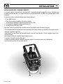
REV 001B
High Quality Nautical Equipment
THRUSTERS COMMAND
TCD 1044
IT
Manuale di installazione ed uso
COMANDO REMOTO TCD
GB
Manual for use and installation
TCD REMOTE CONTROL
FR
Mode d’emploi et d’installation
COMMANDE A DISTANCE TCD
DE
Installations- und Benutzerhandbuch
FERNSTEUERUNG TCD
ES
Manual de instalación y uso
MANDO REMOTO TCD
INDICE
IT
pag. 4
pag. 5
pag. 6
pag. 7
pag. 8
pag. 9
pag. 10/11
pag. 11
pag 12
pag. 13
GB
pag.
pag.
pag.
pag.
pag.
pag.
pag.
pag.
pag
pag.
FR
Seite
Seite
Seite
Seite
Seite
Seite
Seite
Seite
Seite
Seite
DE
pág.
pág.
pág.
pág.
pág.
pág.
pág.
pág.
pág
pág.
ES
pág.
pág.
pág.
pág.
pág.
pág.
pág.
pág.
pág
pág.
CARATTERISTICHE E INSTALLAZIONE
INSTALLAZIONE - Installazione del comando remoto
INSTALLAZIONE - Collegamento elettrico - Schema elettrico dei collegamenti
FUNZIONAMENTO - Comando remoto TCD 1044
FUNZIONAMENTO - Abilitazione del comando remoto - Azionamento del propulsore
FUNZIONAMENTO - Azionamento del propulsore di poppa
FUNZIONAMENTO - Azionamento combinato dei propulsori di prua e di poppa
FUNZIONAMENTO - Disabilitazione - Comandi remoti multipli in parallelo
ERRORI E PROBLEMI DI SISTEMA - Segnalazione errori
MANUTENZIONE - DATI TECNICI
INDEX
14
15
16
17
18
19
20/21
21
22
23
CHARACTERISTICS AND INSTALLATION
INSTALLATION - Installation
INSTALLATION - Electric connections - Electrical connections diagram
OPERATING - TCD 1044 Remote control
OPERATING - Remote control enablement - Activation of thruster
OPERATING - Stern thruster activation
OPERATING - Activation of stern thruster - Combined activation of bow and stern thrusters
OPERATING - Disablement - Multiple remote controls in parallel
SYSTEM ERRORS AND PROBLEMS - Error signal
MAINTENANCE - TECHNICAL DATA
SOMMAIRE
24
25
26
27
28
29
30/31
31
32
33
CARACTÉRISTIQUES ET INSTALLATION
INSTALLATION - Installation
INSTALLATION - Branchement electrique - Schéma electrique des branchements
FONCTIONNEMENT - Commande à distance TCD 1044
FONCTIONNEMENT - Activation de la commande à distance - Actionnement du propulseur
FONCTIONNEMENT - Actionnement du propulseur de poupe
FONCTIONNEMENT - Actionnement combiné des propulseurs d’étrave et de poupe
FONCTIONNEMENT - Désactivation - Commandes à distance multiple en parallele
ERREURS ET PROBLEMES DE SYSTEME - Signal d’erreurs
MAINTENANCE - CARACTÉRISTIQUES TECHNIQUES
INHALTSANGABE
34
35
36
37
38
39
40/41
41
42
43
EIGENSCHAFTEN UND INSTALLATION
INSTALLATION - Installation
INSTALLATION - Stromanschluss - Elektrischer Schaltplan der Verbindungen
BETRIEB - Fernsteuerung TCD 1044
BETRIEB - Fernsteuerfreigabe - Betätigung des Antriebs
BETRIEB - Betätigung des Heck-Antriebs
BETRIEB - Kombinierte Betätigung von Bug- und Heck-Antrieb
BETRIEB - Ausschalten - Parallel geschaltete mehrfache Fernsteuerungen
SYSTEMFEHLER UND PROBLEME - Fehleranzeige
WARTUNG - TECHNISCHE DATEN
INDICE
44
45
46
47
48
49
50/51
51
52
53
TCD1044 - REV001B
CARACTERISTÍCAS E INSTALACIÓN
INSTALACIÓN - Instalación
INSTALACIÓN - Conexión eléctrica - Esquema eléctrico de las conexiones
FUNCIONAMIENTO - Mando remoto TCD 1044
FUNCIONAMIENTO - Habilitación del mando remoto - Accionamiento del propulsor
FUNCIONAMIENTO - Accionamiento del propulsor de popa
FUNCIONAMIENTO - Accionamiento combinado de los propulsores de proa y de popa
FUNCIONAMIENTO - Deshabilitación - Mandos remotos múltiples en paralelo
ERRORES Y PROBLEMAS DEL SISTEMA - Señalación de errores
MANTENIMIENTO - ESPECIFICACIONES TECNICAS
3
IT
CARATTERISTICHE E INSTALLAZIONE
COMANDO REMOTO TCD 1044
Il comando remoto è stato progettato per comandare i propulsori di prua e poppa prodotti da Quick®.
Altri importanti vantaggi che il comando remoto offre sono:
•
•
•
•
•
•
•
•
Interfaccia utente semplice ed intuitiva.
Alimentazione universale (da 8 a 31 Vdc).
Funzionamento in un ampio intervallo di temperature ambiente.
Possibilità di collegare più comandi remoti TCD in parallelo.
Facilità di installazione tramite connettori (prolunghe opzionali).
Sistema di priorità automatica.
Disabilitazione automatica.
Protezione contro l’inversione di polarità, cortocircuito in uscita, attività prolungata dei propulsori e
interruzione del cablaggio di comando dei propulsori.
INSTALLAZIONE
PRIMA DI UTILIZZARE IL COMANDO REMOTO, LEGGERE ATTENTAMENTE IL PRESENTE
MANUALE D'USO. IN CASO DI DUBBI CONTATTARE IL RIVENDITORE O IL SERVIZIO CLIENTI QUICK®.
caso di discordanze o eventuali errori tra il testo tradotto e quello originario in italiano, fare riferiF Inmento
al testo italiano o inglese.
dispositivo è stato progettato e realizzato per essere utilizzato su imbarcazioni da diporto.
F Questo
Non è consentito un utilizzo differente senza autorizzazione scritta da parte della società Quick .
®
Il comando remoto è stato progettato e realizzato per gli scopi descritti in questo manuale d’uso. La
società Quick® non si assume alcuna responsabilità per danni diretti o indiretti causati da un uso improprio
del comando remoto, da una errata installazione o da possibili errori presenti in questo manuale.
LA MANOMISSIONE DEL COMANDO REMOTO DA PARTE DI PERSONALE NON AUTORIZZATO FA
DECADERE LA GARANZIA.
LA CONFEZIONE CONTIENE: comando remoto TCD 1044 - cornice - dima di foratura - condizioni di
garanzia - il presente manuale d’uso.
INSTALLAZIONE DEL COMANDO REMOTO
Di seguito sarà descritta una procedura di installazione tipica.
Non è possibile descrivere una procedura che sia applicabile a tutte le situazioni, adattare questa
procedura per soddisfare i propri requisiti. Individuare la posizione più adatta dove praticare la sede per
alloggiare il comando remoto seguendo questi criteri:
• Il comando remoto deve essere posizionato in modo da essere facilmente manovrabile dall’operatore.
• Scegliere una posizione che sia liscia e piana.
• Deve essere presente un accesso posteriore per l’installazione e la manutenzione.
• Deve esistere spazio sufficiente dietro alla posizione scelta per collocare il retro del comando remoto e i
cablaggi.
• La parte posteriore del comando remoto deve essere protetta da acqua e umidità.
• Porre particolare attenzione quando si effettuano i fori sui pannelli o su parti dell’imbarcazione.
Questi fori non devono indebolire o causare rotture alla struttura dell’imbarcazione.
4
TCD1044 - REV001B
INSTALLAZIONE
IT
INSTALLAZIONE DEL COMANDO REMOTO
Il comando remoto risponde agli standard EMC (compatibilità elettromagnetica) ma è richiesta una
corretta installazione per non compromettere le proprie prestazioni e quelle dei comandi posti nelle
vicinanze.
Per questo motivo il comando deve essere distante almeno:
•
•
•
•
•
25 cm dalla bussola.
50 cm da un qualsiasi apparecchio radio ricevente.
1 m da qualsiasi apparato radiotrasmittente (escluso SSB).
2 m da qualsiasi apparato radiotrasmittente SSB.
2 m dal percorso del fascio radar.
Dopo aver scelto la posizione del comando remoto, procedere come riportato di seguito:
• Posizionare la dima di foratura (fornita in dotazione) sulla superficie dove sarà installato il comando remoto.
• Marcare il centro di ogni foro.
• Realizzare il foro per il retro del comando remoto con una fresa diametro 63 mm e tagliare lungo il perimetro indicato.
• Rimuovere la dima ed eventuali bave presenti sui fori.
• Inserire il comando remoto nella sede.
• Fissare il comando remoto al pannello tramite quattro viti a testa svasata (non in dotazione).
• Posizionare la cornice sul comando remoto.
TCD1044 - REV001B
5
IT
INSTALLAZIONE
COLLEGAMENTO ELETTRICO
Il comando remoto risponde agli standard EMC (compatibilità elettromagnetica) ma è richiesta una corretta
installazione per non compromettere le proprie prestazioni e quelle dei comandi posti nelle vicinanze.
Per questo motivo i cavi del comando remoto devono essere distanti almeno:
• 1 m dai cavi che trasportano segnale radio (escluso radiotrasmittenti SSB).
• 2 m dai cavi che trasportano segnale radio di radiotrasmittenti SSB.
Seguire le regole riportate di seguito per la realizzazione dell’impianto elettrico relativo al comando remoto:
• Collegare i connettori del comando remoto, ai connettori provenienti dai propulsori di manovra.
• Inserire un interruttore per accendere e spegnere il comando remoto (non in dotazione).
• Posizionare l’interruttore in modo che sia facilmente raggiungibile nel caso in cui sia necessario
spegnere l’apparecchio per evitare situazioni di pericolo.
• Inserire un fusibile da 8A rapido sulla linea di alimentazione del comando remoto (non in dotazione).
• Dimensionare correttamente la sezione dei cavi di alimentazione del comando remoto in funzione della
loro lunghezza.
• Non utilizzare la tensione proveniente dal gruppo batterie motori o propulsori per alimentare il comando
remoto.
• Alimentare il comando remoto solo dopo aver effettuato e verificato l’esattezza di tutti i collegamenti
elettrici.
SCHEMA ELETTRICO DEI COLLEGAMENTI
PROPULSORE POPPA
STACCABATTERIA
MOTORE
ROSSO
NERO
FUSIBILE
PROPULSORE PRUA
INTERRUTTORE
STACCABATTERIA
MOTORE
PROLUNGHE
(OPZIONALI)
FUSIBILE
*
BATTERIA
SERVIZI
FUSIBILE
*
BATTERIA
PROPULSORI
* Negativo dei gruppi batteria in comune.
6
TCD1044 - REV001B
FUNZIONAMENTO
IT
FUNZIONAMENTO DEL COMANDO REMOTO
L’interfaccia utente è composta da 1 pulsante di abilitazione, 2 joystick, 2 led di abilitazione e 4 led di direzione.
JOYSTICK DI PRUA
LED DI DIREZIONE SINISTRA PRUA
LED DI DIREZIONE DESTRA PRUA
JOYSTICK DI POPPA
LED DI DIREZIONE SINISTRA POPPA
LED DI DIREZIONE DESTRA POPPA
LED DI ABILITAZIONE
LED DI ABILITAZIONE
PULSANTE DI ABILITAZIONE
Pulsante di abilitazione
Il pulsante abilita o disabilita il comando remoto.
Joystick di prua
Quando il joystick di prua viene spostato a destra, a fine corsa, si muove la prua dell’imbarcazione a destra.
Quando il joystick di prua viene spostato a sinistra, a fine corsa, si muove la prua dell’imbarcazione a sinistra.
Joystick di poppa
Quando il joystick di poppa viene spostato a destra, a fine corsa, si muove la poppa dell’imbarcazione a destra.
Quando il joystick di poppa viene spostato a sinistra, a fine corsa, si muove la poppa dell’imbarcazione a sinistra.
Led di abilitazione
I led di abilitazione segnalano lo stato di abilitazione / disabilitazione del comando remoto.
Led di direzione
I led di direzione segnalano il movimento verso destra o sinistra.
Tutti i led inoltre sono utilizzati per segnalare eventuali errori o problemi.
Utilizzare l’interruttore posto sulla linea di alimentazione per accendere e spegnere il comando remoto.
Una volta collegata l’alimentazione il comando remoto effettua il test dei led.
Il test dei led avviene accendendo contemporaneamente tutti i led per 2 secondi.
Se non vengono rilevati errori o problemi il comando remoto si pone nello stato disabilitato (vedi
disabilitazione del comando remoto).
ATTENZIONE: esercitarsi ad azionare i propulsori in acque libere, per evitare di danneggiare
l’imbarcazione con manovre avventate.
TCD1044 - REV001B
7
IT
FUNZIONAMENTO
ABILITAZIONE DEL COMANDO REMOTO
Per abilitare il comando remoto premere e tenere premuto il pulsante di abilitazione per almeno 1 secondo.
Trascorso questo periodo i led di abilitazione inizieranno a lampeggiare con una frequenza maggiore.
Rilasciando il pulsante di abilitazione, i led rimarranno accesi in maniera permanente e il comando remoto
risulterà abilitato.
AZIONAMENTO DEL PROPULSORE
Azionamento del propulsore di prua
Per muovere a destra la prua, muovere verso destra, a fine corsa, la leva del joystick
di prua.
Per muovere a sinistra la prua, muovere
verso sinistra, a fine corsa, la leva del joystick
di prua.
Durante la fase di azionamento del propulsore, il relativo led di direzione si accenderà in maniera permanente.
ATTENZIONE: una volta rilasciato il joystick di direzione, l’imbarcazione continuerà a muoversi a
causa dell’inerzia del moto.
8
TCD1044 - REV001B
FUNZIONAMENTO
IT
Azionamento del propulsore di poppa
Per muovere a destra la poppa, muovere
verso destra, a fine corsa, la leva del joystick
di poppa.
Per muovere a sinistra la poppa, muovere
verso sinistra, a fine corsa, la leva del joystick
di poppa.
Durante la fase di azionamento del propulsore, il relativo led di direzione si accenderà in maniera permanente.
ATTENZIONE: una volta rilasciato il joystick di direzione, l’imbarcazione continuerà a muoversi a
causa dell’inerzia del moto.
TCD1044 - REV001B
9
IT
FUNZIONAMENTO
Azionamento combinato dei propulsori di prua e di poppa
La combinazione di un propulsore di prua e di un propulsore di poppa offre la massima manovrabilità dell’imbarcazione con la possibilità di muovere la prua e la poppa indipendentemente l’una dall’altra.
Ciò consente di muovere l’imbarcazione lateralmente in entrambe le direzioni e di far girare l’imbarcazione in senso orario e antiorario.
prua a destra
poppa a destra
prua a sinistra
poppa a sinistra
ATTENZIONE: una volta rilasciati i joystick di direzione, l’imbarcazione continuerà a muoversi a
causa dell’inerzia del moto.
10
TCD1044 - REV001B
FUNZIONAMENTO
IT
prua a destra
poppa a sinistra
prua a sinistra
poppa a destra
ATTENZIONE: una volta rilasciati i joystick di direzione, l’imbarcazione continuerà a muoversi a
causa dell’inerzia del moto.
Nota:
Il comando remoto introduce un ritardo di 2 secondi nel caso in cui il propulsore sia azionato in una direzione e si tenti di azionarlo nella direzione opposta (passaggio immediato da destra a sinistra o viceversa).
DISABILITAZIONE DEL COMANDO REMOTO
La disabilitazione, con il comando remoto abilitato, si ha nei seguenti casi:
• Premendo il pulsante di abilitazione.
• Quando, con più comandi remoti in parallelo, se ne abilita un altro.
• Dopo 6 minuti se non si spostano i joystick (dall'ultimo comando eseguito).
In questo stato, i led di abilitazione lampeggiano a bassa frequenza e i joystick sono disabilitati.
COMANDI REMOTI MULTIPLI IN PARALLELO
E’ possibile installare più comandi remoti della serie TCD in parallelo. In questo caso, si ha il funzionamento di un solo comando remoto alla volta. Il comando remoto attivo è sempre l’ultimo che
viene abilitato; gli altri comandi remoti posti in parallelo vengono automaticamente disabilitati.
Quando si comanda il propulsore dall’ultimo comando remoto abilitato, la direzione del movimento
dell’imbarcazione sarà segnalata dall’accensione del relativo led anche sugli altri comandi remoti
disabilitati.
TCD1044 - REV001B
11
IT
ERRORI E PROBLEMI DI SISTEMA
ERRORI DI SISTEMA
Durante la fase di accensione il comando remoto può segnalare la presenza di errori di sistema.
Errore checksum flash
Nel caso in cui venga riscontrato l’errore, tutti i led lampeggiano velocemente.
In questo caso è necessario contattare al più presto un punto assistenza o il servizio clienti Quick®.
PROBLEMI DI SISTEMA
Di seguito si riportano i problemi di sistema, suddivisi in due categorie:
problemi con reset automatico e problemi con reset manuale.
PROBLEMI CON RESET AUTOMATICO
Il reset di questa classe di problemi avviene automaticamente, non appena scompare la causa che
ha generato il problema.
Bassa tensione di alimentazione
Il problema è segnalato se la tensione di alimentazione scende al di sotto di 10.5Vdc per più di un
secondo. Il reset del problema avviene se la tensione di alimentazione supera la soglia di 11.5Vdc
per più di un secondo. Verificare lo stato di carica del gruppo batterie da cui è derivata l’alimentazione o l’impianto elettrico.
In presenza del problema i led di abilitazione si spengono per un breve istante.
Protezione contro l’attività prolungata del motore
Dopo 5 minuti circa di azionamento continuo del singolo propulsore, il comando al relativo propulsore si interrompe. In presenza del problema lampeggiano entrambi i led di direzione. Il reset del
problema avviene automaticamente trascorso un periodo di tempo, calcolato dal comando remoto,
necessario al parziale raffreddamento del propulsore.
PROBLEMI CON RESET MANUALE
Il reset di questa classe di problemi avviene spegnendo e riaccendendo il comando remoto.
Sovraccarico sulla linea elettrica di comando
Il problema è segnalato nel caso in cui il comando remoto rilevi un corto circuito o un sovraccarico
sulla linea elettrica di comando del propulsore. In presenza del problema lampeggiano lentamente il
led relativo alla linea elettrica di comando sulla quale è stata rilevata l'anomalia e i led di abilitazione.
Verificare il cablaggio delle linee elettriche dal comando remoto al propulsore e l’assorbimento dei
teleruttori installati sul propulsore.
Interruzione della linea elettrica di comando
Il problema è segnalato nel caso in cui il comando remoto rilevi un’interruzione della linea elettrica
di comando del propulsore. In presenza del problema lampeggiano velocemente il led relativo alla
linea elettrica di comando sulla quale è stata rilevata l'anomalia e i led di abilitazione.
Verificare il cablaggio delle linee elettriche dal comando remoto al propulsore.
12
TCD1044 - REV001B
MANUTENZIONE - DATI TECNICI
IT
MANUTENZIONE
Il comando remoto non richiede una particolare manutenzione. Per assicurare il funzionamento ottimale del
comando remoto verificare, una volta all’anno, i cavi e le connessioni elettriche.
Pulire il comando remoto con un panno morbido inumidito d’acqua. Non utilizzare prodotti chimici o abrasivi per pulire il comando remoto.
CARATTERISTICHE TECNICHE
TCD 1044
MODELLO
CARATTERISTICHE DI USCITA
Portata in corrente dei comandi destro o
sinistro del singolo propulsore.
4A max
CARATTERISTICHE DI INGRESSO
Tensione di alimentazione (1)
da 8 a 31 Vdc
Assorbimento (2)
Assorbimento massimo (3)
10 mA
95 mA + assorbimento bobina teleruttore
CARATTERISTICHE AMBIENTALI
Temperatura operativa
da -20 a +70 °C
Grado di protezione (4)
IP 66
GENERALI
Dimensioni compreso cornice (L x L)
78 mm x 131 mm
Peso
(1)
(2)
(3)
(4)
250 g
Con tensione di alimentazione inferiore a 8 Vdc il comando remoto può resettarsi.
Valore tipico con comando remoto disabilitato.
Valore tipico con comando remoto abilitato ed entrambi i joystick azionati.
Escluso retro del comando remoto (IP20).
QUICK® SI RISERVA IL DIRITTO DI APPORTARE MODIFICHE ALLE CARATTERISTICHE TECNICHE DELL'APPARECCHIO E AL CONTENUTO DI QUESTO MANUALE SENZA ALCUN PREAVVISO.
TCD1044 - REV001B
13
GB
CHARACTERISTICS AND INSTALLATION
TCD 1044 REMOTE CONTROL
The remote control is designed to control the stern and bow thrusters manufactured by Quick®.
Other important advantages of the remote control are:
•
•
•
•
•
•
•
•
Simple and intuitive user interface.
Universal supply (from 8 to 31 Vdc).
Can work in a wide range of ambient temperatures.
Possibility of connecting several TCD remote controls in parallel.
Easy to install by means of connectors (optional extensions).
Automatic priority system.
Automatic disabling.
Protection against reverse polarity, output short circuit, prolonged activity of thrusters and interruption
of thrusters controls wiring.
INSTALLATION
BEFORE USING THE REMOTE CONTROL, READ THIS INSTRUCTION MANUAL CAREFULLY.
IN CASE OF DOUBTS, CONTACT QUICK® CUSTOMER SERVICE OR YOUR LOCAL DEALER.
of discordance or errors in translation between the translated version and the original text in
F Inthecase
Italian language, reference will be made to the Italian or English text.
device was designed and constructed for use on recreational crafts.
F This
Other forms of use are not permitted without written authorization from the company Quick .
®
The remote control is designed and constructed for the purposes described in this instruction manual.
Quick® shall not be held responsible for any direct or indirect property damage or personal injury caused
by inappropriate or unintended use of the remote control, incorrect installation or any errors that may be
present in this manual.
THE WARRANTY SHALL BE VOID IF THE REMOTE CONTROL IS TAMPERED WITH OR ALTERED BY
NON AUTHORISED PERSONNEL.
THE PACKAGE CONTAINS: TCD 1044 remote control - frame - drilling template - conditions of warranty
- user's manual.
INSTALLATION OF THE REMOTE CONTROL
The typical installation procedure is described herein, it is not possible to describe a procedure applicable
for all situations that may be encountered.
Adapt this procedure to satisfy your own personal requirements.
Locate the most suitable position to house the remote control following the recommendations given
below:
•
•
•
•
The remote control must be positioned so that it can easily be manoeuvred by the operator.
Select a smooth and flat area.
Access from the rear must be available for installation and maintenance purposes.
There must be enough space behind the chosen position in order to accommodate the rear of the
remote control and the wires.
• The rear part of the remote control must be protected from water and damp.
• Pay careful attention when drilling the panels or parts of the boat.
These holes should not weaken or break/crack the boat's structure.
14
TCD1044 - REV001B
INSTALLATION
GB
INSTALLATION OF THE REMOTE CONTROL
The remote control complies with EMC standards (electromagnetic compatibility) but requires correct
installation to avoid compromising its performance and that of the surronding instruments.
For this reason the remote control must be positioned at a distance of at least:
•
•
•
•
•
25 cm away from the compass.
50 cm away from any radio receivers.
1 m away from any radio transmitters (except for SSB).
2 m away from any radio transmitters SSB.
2 m away from the path of the radar beam.
After choosing where to position the remote control, proceed as follows:
•
•
•
•
•
•
•
Position the drilling template (provided) on the surface where the remote control will be installed.
Mark the centre of each hole.
Drill the hole for the back of the remote control with a 63 mm bit and cut along the perimeter indicated.
Remove the template and any burrs present in the holes.
Insert the remote control into its seat.
Fix the remote control to the panel with four countersunk head screws (not provided).
Position the frame on the remote control.
TCD1044 - REV001B
15
GB
INSTALLATION
ELECTRIC CONNECTIONS
The remote control complies with EMC standards (electromagnetic compatibility) but requires correct
installation to avoid compromising its performance and that of the surronding instruments.
For this reason the remote control wires must be positioned at a distance of at least:
• 1 m away from cables that carry radio signals (except SSB radio transmitters).
• 2 m away from cables for SSB radio transmitter signals.
Follow the rules below to construct the electrical installation relative of the remote control:
• Connect the remote control connectors to the connectors coming from the thrusters.
• Put in a switch, to turn on and shut off the remote control (not provided).
• Position the switch so that it is within easy reach should it be necessary to shut off the remote control
in an emergency.
• Insert a 8A quick-acting fuse on the remote control power supply line (not provided).
• Use wires, for the remote control power supply, with a correct cross section according to their length.
• Do not use supply from the motors or thrusters battery circuit for the remote control.
• Before switching on the power to the remote control, check that all the electrical connections are correct.
ELECTRICAL CONNECTIONS DIAGRAM
BATTERY
ISOLATOR
STERN THRUSTER
MOTOR
RED
BLACK
FUSE
BOW THRUSTER
SWITCH
BATTERY
ISOLATOR
MOTOR
CONTROL CABLE
EXTENSIONS
(OPTIONALS)
FUSE
*
SERVICE
BATTERY
FUSE
*
THRUSTERS
BATTERY
* Common negative for the battery groups.
16
TCD1044 - REV001B
OPERATING
GB
REMOTE CONTROL FUNCTIONING
The user interface of the is composed of one enabling button, 2 joystick, 2 enabling leds and 4 direction
leds.
BOW JOYSTICK
BOW LEFT DIRECTION LED
BOW RIGHT DIRECTION LED
STERN JOYSTICK
STERN LEFT DIRECTION LED
STERN RIGHT DIRECTION LED
ENABLING LED
ENABLING LED
ENABLING BUTTON
Enabling button
The button enables or disables the remote control.
Bow Joystick
When the bow joystick is moved to the right at the end of its stroke, it moves the bow of the boat to the
right.
When the bow joystick is moved to the left at the end of its stroke, it moves the bow of the boat to the left.
Stern Joystick
When the stern joystick is moved to the right at the end of its stroke, it moves the stern of the boat to the
right.
When the stern joystick is moved to the left at the end of its stroke, it moves the stern of the boat to the left.
Enabling leds
The enabling leds indicate the enabled/disabled state of the remote control.
Direction leds
The direction leds indicate the movement of the boat to the right or left.
All leds are also used to signal any errors or problems.
Use the switch on the supply line to switch the remote control on and off. Once the supply has been connected, the remote control will test the leds. For the led test, all the leds will come on simultaneously for
2 seconds. If no errors or problems are detected, the remote control will then go to the disabled state (see
remote control disablement).
WARNING: practice controlling the thrusters in open water, to avoid damaging the boat with accidentally wrong manoeuvres.
TCD1044 - REV001B
17
GB
OPERATING
REMOTE CONTROL ENABLING
To enable the remote control, press the enabling button and keep it pressed for at least 1 second.
After this time, the enabling leds will start flashing faster. When you release the enabling button, the leds
will stay on indicating that the remote control is enabled.
THRUSTER ACTIVATION
Bow thruster activation
To move the bow to the right, move the bow
joystick to the right at the end of its stroke.
To move the bow to the left, move the bow
joystick to the left at the end of its stroke.
When controlling the thruster, the relative direction led will remain on.
WARNING: once the direction joystick has been released, the boat will continue to move according to the inertia of the movement.
18
TCD1044 - REV001B
OPERATING
GB
Stern thruster activation
To move the stern to the right, move the
stern joystick to the right at the end of its
stroke.
To move the stern to the left, move the stern
joystick to the left at the end of its stroke.
When controlling the thruster, the relative direction led will remain on.
WARNING: once the direction joystick has been released, the boat will continue to move according to the inertia of the movement.
TCD1044 - REV001B
19
GB
OPERATING
Combined activation of bow and stern thrusters.
The combination of bow and stern thrusters gives maximum possibility of manoeuvring the boat, since
the bow and stern can be moved independently of each other.
This allows the boat to be moved sideways in both directions and to rotate the boat in a clockwise and
anticlockwise direction.
bow to the right
stern to the right
bow to the left
stern to the left
WARNING: once the direction joystick has been released, the boat will continue to move according to the inertia of the movement.
20
TCD1044 - REV001B
OPERATING
GB
bow to the right
stern to the left
bow to the left
stern to the right
WARNING: once the direction joystick has been released, the boat will continue to move according to the inertia of the movement.
Note:
There is a delay of 2 seconds if the thruster is activated in one direction and then immediately activated in
the opposite direction (immediate movement from right to left or vice versa).
DISABLING OF THE REMOTE CONTROL
The remote control is disabled in the following cases:
• When the enabling button is pressed.
• When there are several remote controls in parallel and another is activated.
• If the joystick haven't been operated for a 6 minutes time.
In this state, the enablement leds flash slowly and the joystick are disabled.
MULTIPLE REMOTE CONTROLS IN PARALLEL
Several TCD series remote controls can be installed in parallel. In this case, only one remote control
can function at a time. The active remote control is always the last one to be activated; the other
in parallel are automatically disabled. When a thruster is commanded by the last remote control
enabled, the boat movement direction will be indicated by the relative led which will light up also on
the other disabled remote controls.
TCD1044 - REV001B
21
GB
SYSTEM ERRORS AND PROBLEMS
SYSTEM ERRORS
When the remote control is switched on, it may signal the presence of system errors.
Checksum error flash
If the error is detected, all the leds will flash quickly.
In this case an assistance point or the Quick® customer service must be contacted as soon as possible.
SYSTEM PROBLEMS
System problems are listed below, divided into two categories:
automatic reset problems and manual reset problems.
AUTOMATIC RESET PROBLEMS
Resetting after problems of this type occurs automatically, as soon as the cause that has generated
the problem disappears.
Low voltage supply
The problem is signalled if the power supply voltage descends below 10.5Vdc for more than one
second. Resetting after this problem occurs if the power supply voltage exceeds the threshold of
11.5Vdc for more than one second. Check the charge state of the battery group that supplies is
derived or the electrical circuit.
In the case of this problem, the enabling leds go off for a moment.
Protection against prolonged motor activity
After activating the single thruster for about 5 minutes continuously, the relevant thruster command
is interrupted.
In this case, both direction leds will flash. Resetting after this problem occurs automatically after a
period of time, calculated by the remote control, necessary to partially cool the thruster.
MANUAL RESET PROBLEMS
Reset problems of this kind occur shut off and turn on the remote control.
Overload on the command electrical line
This problem is signalled when the remote control finds a short circuit or overload on the thruster
command electrical line. In the case of this problem, the leds relative to the command electrical line
on which the anomaly has been detected and the enabling leds flash slowly.
Check the wiring of the electrical lines from the remote control to the thruster and absorption of the
contactors installed on the thruster.
Interruption on the command electrical line
This problem is signalled when the remote control finds an interruption on the thruster command
electrical line. In the case of this problem, the leds relative to the command electrical line on which
the anomaly has been detected and the enabling leds flash fast.
Check the wiring of the electrical lines from the remote control to the thruster.
22
TCD1044 - REV001B
MAINTENANCE - TECHNICAL DATA
GB
MAINTENANCE
The remote control needs no particular maintenance. To ensure optimum performance from the remote
control, once a year check the cables and the electrical connections.
Clean the remote control with a soft cloth dampened with water. Do not use chemical or abrasive products
to clean the remote control.
TECHNICAL DATA
TCD 1044
MODEL
OUTPUT CHARACTERISTICS
Current capacity of right or left single thruster
commands.
4A max
INPUT CHARACTERISTICS
Supply voltage (1)
from 8 to 31 Vdc
Current absorption (2)
Maximum current absorption (3)
10 mA
95 mA + absorption of the contactor coil
AMBIENT CHARACTERISTICS
Operating temperature
Protection rating (4)
from -20 to +70 °C
IP 66
GENERAL
Dimensions including frame (L x L)
Weight
(1)
(2)
(3)
(4)
78 mm x 131 mm
250 g
With supply voltage less than 8 Vdc the remote control can reset.
Typical value with remote control disabled.
Typical value with remote control enabled and both joysticks activated.
Excluding the back of the remote control (IP20).
QUICK® RESERVES THE RIGHT TO MODIFY THE TECHNICAL CHARACTERISTICS OF THE EQUIPMENT AND THE CONTENTS OF THIS MANUAL WITHOUT PRIOR NOTICE.
TCD1044 - REV001B
23
FR
CARACTÉRISTIQUES ET INSTALLATION
COMMANDE A DISTANCE TCD 1044
La commande à distance a été étudiée afin de commander les propulseurs d'étrave ou de poupe produits
par Quick®.
Voici d’autres avantages importants que la commande à distance offre:
•
•
•
•
•
•
•
•
Interface utilisateur simple et intuitive.
Alimentation électrique universelle (de 8 à 31 Vdc).
Fonctionnement dans une large gamme de temperature.
Possibilité de brancher plusieurs commandes à distance en parallèle.
Facilité d’installation au moyen de connecteurs (rallonges en option).
Système de priorité automatique.
Désactivation automatique.
Protection contre l’inversion de polarité, court-circuit en sortie, activité prolongée des propulseurs et
interruption du câblage de commande des propulseurs.
INSTALLATION
AVANT D’UTILISER LA COMMANDE A DISTANCE, LIRE ATTENTIVEMENT CE MANUEL D’UTILISATION.
EN CAS DE DOUTE, CONTACTER LE REVENDEUR OU LE SERVICE APRES VENTE CLIENTS QUICK®.
cas de discordances ou d’erreurs éventuelles entre la traduction et le texte original en italien, se
F Enréférer
au texte italien ou anglais.
a été conçu et réalisé pour être utilisé sur des bateaux de plaisance.
F CeToutdispositif
autre emploi est interdit sans autorisation écrite de la société Quick .
®
La commande à distance a été étudiée et réalisée pour les buts décrits dans ce manuel d’utilisation. La
société Quick® ne peut être tenue responsable des dommages directs ou indirects causés par une utilisation impropre de la commande à distance, par une mauvaise installation ou par de possible erreurs
présentes dans ce livret.
LA GARANTIE N’EST PAS VALABLE SI LA COMMANDE EST OUVERTE PAR UN PERSONNEL NON AUTORISE.
L'EMBALLAGE COMPREND: commande à distance TCD 1044 - châssis - gabarit de perçage - conditions de
garantie - manuel de l'utilisateur.
INSTALLATION DE LA COMMANDE A DISTANCE
Ci-dessous nous avons décrit une procédure d'installation typique. Il est impossible de décrire une procédure qui soit applicable à toutes les situations. Adapter cette procédure afin de répondre à vos exigences
propres. Trouver la position la plus adaptée pour réaliser les logements qui vont recevoir la commande à
distance en suivant les critères suivants:
• La commande à distance doit être placée de façon à être facilement manœuvrable par l’opérateur.
• Il doit y avoir un espace suffisant derrière la position choisie pour placer l’arrière de la commande ainsi
que les câblages.
• L'arrière de la commande à distance doit être protégé contre l'eau ou l'humidité.
• Il doit y avoir un espace suffisant derrière la position choisie pour placer le dos de a commande à distance à distance et les connecteurs.
• La partie arrière de la commande à distance doit être protégée contre tout contact avec l'eau et l'humidité.
• Faire particulièrement attention quand vous réalisez les orifices sur les panneaux ou sur certaines
parties de l'embarcation.
Ces orifices ne doivent pas fragiliser ou causer la rupture de la structure de l'embarcation.
24
TCD1044 - REV001B
INSTALLATION
FR
INSTALLATION DE LA COMMANDE A DISTANCE
La commande à distance est conforme aux standards EMC (compatibilité électromagnétique), mais une
bonne installation est requise afin de ne pas compromettre ses performances ainsi que celles des commandes situées à proximité.
Pour ce motif, la commande doit être distant d’au moins:
•
•
•
•
•
25 cm du compas.
25 cm de tout appareil radio récepteur.
1 m de tout appareil radio de transmission (excepté SSB).
2 m de tout appareil radio de réception et transmission SSB.
2 m du parcours suivi du faisceau radar.
Après avoir choisi la position de la commande à distance, procéder comme indiqué ci-après:
• Placer le gabarit de perçage (livré avec le produit) sur la surface où la commande à distance sera installée.
• Marquer le centre de chaque orifice.
• Réaliser la découpe pour le dos de la commande à distance avec une fraise de diamètre 63 mm et découper en suivant le périmètre indiqué.
• Retirer le gabarit et les éventuelles ébarbures présentes sur les orifices.
• Insérer la commande à distance dans le logement.
• Fixer la commande à distance au panneau avec quatre vis à tête évasée (non fournies).
• Placer le châssis sur la commande à distance.
TCD1044 - REV001B
25
FR
INSTALLATION
BRANCHEMENT ELECTRIQUE
La commande à distance est conforme aux standards EMC (compatibilité électromagnétique), mais une bonne
installation est requise afin de ne pas compromettre ses performances ainsi que celles des commandes situées
à proximité.
Pour ce motif, les câbles de la commande à distance doivent être distants d’au moins:
• 1 m des câbles des signaux radio (excepté les appareils radio de réception et de transmission SSB)
• 2 m des câbles des signaux radio pour appareils de réception et de transmission SSB.
Suivre les règles indiquées ci-après pour réaliser l’installation électrique relative à la commande à distance:
• Brancher les connecteurs de la commande à distance, aux connecteurs provenants des propulseurs de
manœuvre.
• Introduire un interrupteur pour allumer et éteindre la commande à distance (non fournies).
• Placer l’interrupteur de manière à ce qu’il soit facilement accessible s'il était nécessaire d’arrêter la commande à distance afin d’éviter des situations de danger.
• Insérer un fusible de 8A rapide sur la ligne d’alimentation de la commande à distance (non fournies).
• Dimensionner correctement la section des câbles d'alimentation de la commande à distance en fonction de
leur longueur.
• Ne pas utiliser la tension provenant du groupe batteries moteurs ou propulseurs pour alimenter la commande à
distance.
• Alimenter la commande à distance uniquement après avoir effectué et vérifié l’exactitude de tous les branchements électriques.
SCHEMA ELECTRIQUE DES BRANCHEMENTS
PROPULSEUR DE POUPE
COUPEBATTERIE
MOTEUR
ROUGE
NOIRE
FUSIBLE
PROPULSEUR D'ÈTRAVE
INTERRUPTEUR
COUPEBATTERIE
MOTEUR
RALLONGES
(EN OPTION)
FUSIBLE
*
BATTERIE
SERVICES
FUSIBLE
*
BATTERIE
PROPULSEURS
* Négatif des groupes batterie en commun.
26
TCD1044 - REV001B
FONCTIONNEMENT
FR
FONCTIONNEMENT DE LA COMMANDE A DISTANCE
L’interface utilisateur est composée d’un bouton d'activation, 2 joystick, 2 led d’activation et 4 led de direction.
JOYSTICK D'ÉTRAVE
LED DE DIRECTION GAUCHE ÉTRAVE
BOUTON DE DIRECTION DROITE ÉTRAVE
JOYSTICK DE POUPE
BOUTON DE DIRECTION GAUCHE POUPE
BOUTON DE DIRECTION DROITE POUPE
LED D’ACTIVATION
LED D’ACTIVATION
BOUTON D'ACTIVATION
Bouton d'activation
Le bouton active ou désactive la commande à distance.
Joystick d'étrave
Le mouvement à droite du levier du joystick d'étrave, en butée, déplace l'étrave du bateau à droite.
Le mouvement à gauche du levier du joystick d'étrave, en butée, déplace l'étrave du bateau à gauche.
Joystick de poupe
Le mouvement à droite du levier du joystick de poupe, en butée, déplace la poupe du bateau à droite.
Le mouvement à gauche du levier du joystick de poupe, en butée, déplace la poupe du bateau à gauche.
Led d’activation
Les led d'activation signalent l'état d'activation / désactivation de la commande à distance.
Led de direction
Les led de direction signalent le mouvement du bateau vers la droite ou la gauche.
Tous les led sont utilisés pour signaler les erreurs ou problèmes éventuels.
Utiliser l’interrupteur placé sur la ligne d’alimentation pour allumer et éteindre la commande à distance.
Dès que l’alimentation est branchée, la commande à distance effectue le test des led. Le test des led se
fait en allumant simultanément tous les led pendant 2 secondes. Si aucune erreur ou aucun problème
n’est relevé, la commande à distance se place en état de désactivation (voir désactivation de la commande à distance).
ATTENTION: s’exercer à actionner les propulseurs en eaux libres, afin d’éviter d’endommager le
bateau en effectuant des manœuvres hasardeuses.
TCD1044 - REV001B
27
FR
FONCTIONNEMENT
ACTIVATION DE LA COMMANDE A DISTANCE
Pour activer la commande à distance, il faut appuyer et maintenir le bouton d'activation enfoncé pendant
au moins 1 second. Passé ce temps, les led d'activation commenceront à clignoter avec une plus grande
fréquence. En relâchant le bouton d'activation, les led resteront allumés de manière permanente et la
commande à distance sera activée.
ACTIONNEMENT DU PROPULSEUR
Actionnement du propulseur d’étrave
Pour déplacer l’étrave à droite, déplacer le
levier du joystick d'étrave vers la droite, en
butée.
Pour déplacer l’étrave à gauche, déplacer
le levier du joystick d'étrave vers la gauche,
en butée.
Pendant la phase d’actionnement du propulseur, le led de direction s’allume de manière permanente.
ATTENTION: dès que le joystick de direction est relâché, le bateau continuera à se déplacer à
cause du mouvement d’inertie.
28
TCD1044 - REV001B
FONCTIONNEMENT
FR
Actionnement du propulseur de poupe
Pour déplacer l’étrave à droite, déplacer le
levier du joystick de poupe vers la droite, en
butée.
Pour déplacer la poupe à gauche, déplacer
le levier du joystick de poupe vers la gauche,
en butée.
Pendant la phase d’actionnement du propulseur, le led de direction s’allume de manière permanente.
ATTENTION: dès que le joystick de direction est relâché, le bateau continuera à se déplacer à
cause du mouvement d’inertie.
TCD1044 - REV001B
29
FR
FONCTIONNEMENT
Actionnement combiné des propulseurs d’étrave et de poupe
La combinaison d’un propulseur d’étrave et d’un propulseur de poupe offre une plus grande manœuvrabilité du bateau avec la possibilité de déplacer l'étrave et la poupe indépendamment l’une de l’autre. Ceci
permet de déplacer le bateau latéralement dans les deux directions et de faire tourner le bateau dans le
sens des aiguilles et inverse.
le sens des aiguilles et inverse.
étrave à droite
poupe à droite
étrave à gauche
poupe à gauche
ATTENTION: dès que les joystick de direction est relâché, le bateau continuera à se déplacer à
cause du mouvement d’inertie.
30
TCD1044 - REV001B
FONCTIONNEMENT
FR
étrave à droite
poupe à gauche
étrave à gauche
poupe à droite
ATTENTION: dès que les joystick de direction est relâché, le bateau continuera à se déplacer à
cause du mouvement d’inertie.
Note: La commande à distance introduit un retard de 2 secondes si le propulseur est actionné dans une
direction et que l'on tente de l'actionner dans la direction opposée (passage immédiat de la droite vers la
gauche ou vice-versa).
DESACTIVATION DE LA COMMANDE A DISTANCE
La désactivation, avec la commande à distance activée, s’obtient dans les cas suivants:
• En appuyant sur le bouton de désactivation.
• Quand on active une autre commandes à distance, avec plusieurs commandes en parallèle.
• Après 6 minutes, du dernier usage si on ne déplace pas les joystick.
Dans cet état, les led d’activation clignotent à basse fréquence et les joystick sont désactivés.
COMMANDES A DISTANCE MULTIPLE EN PARALLELE
Il est possible d’installer plusieurs commandes à distance de la série TCD en parallèle. Dans ce cas,
on obtient le fonctionnement d’une seule commande à distance à la fois. La commande active est
toujours la dernière qui est activée; les autres commandes à distance mises en parallèle sont automatiquement désactivées.
Lorsqu'on commande le propulseur à partir de la dernière commande à distance activée, la direction du mouvement du bateau sera signalée par l’allumage du led correspondant également sur les
autres commandes à distance désactivées.
TCD1044 - REV001B
31
FR
ERREURS ET PROBLEMES DE SYSTEME
ERREURS DE SYSTEME
Lors de la phase d’allumage, la commande à distance peut signaler la présence d’erreurs de système.
Erreur checksum flash
Si cette erreur est relevée, tous les led clignotent rapidement.
Dans ce cas contacter rapidement un point d’assistance ou bien le service clientèle Quick®.
PROBLEMES DE SYSTEME
Voici, ci-après, les problèmes de système, subdivisés en deux catégories:
Problèmes avec remise à zéro automatique et avec remise à zéro manuelle.
PROBLEMES AVEC REMISE A ZERO AUTOMATIQUE
La remise à zéro de ce type de problème se fait automatiquement, dès que la cause qui a généré le
problème disparaît.
Tension d’alimentation basse
Le problème est signalé si la tension d’alimentation descend au-dessous de 10.5Vdc pendant plus
d’une seconde. La remise à zéro du problème s’effectue si la tension d’alimentation dépasse le seuil
de 11.5Vdc pendant plus d’une seconde. Vérifier l’état de charge du groupe batteries à partir duquel
provient l’alimentation ou l’installation électrique.
En présence de ce problème, les led d’activation s’éteignent pendant un court instant.
Protection contre l’activité prolongée du moteur
Après environ 5 minutes d’actionnement continu de chaque propulseur, la commande à distance
relative au propulseur s’interrompt. En présence de ce problème, les deux led de direction clignotent.
La remise à zéro du problème s’effectue automatiquement, dès que le délai nécessaire, pour le partiel refroidissement du moteur calculé par la commande à distance se soit écoulé.
PROBLEMES AVEC REMISE A ZERO MANUELLE
La remise à zéro de ce type de problème s’effectue en éteignant et en rallumant la commande à
distance.
Surcharge sur la ligne électrique de la commande
Le problème est signalé si la commande à distance relève un court-circuit ou une surcharge sur la
ligne électrique de commande du propulseur. En présence de ce problème, le led correspondant à
la ligne électrique de commande sur laquelle l’anomalie a été relevée ainsi que les led d’activation
clignotent.
Vérifier le câblage des lignes électriques du commande à distance au propulseur et l'absorption des
télérupteurs installés sur propulseur.
Interruption de la ligne électrique de commande
Le problème est signalé si la commande à distance relève une interruption de la ligne électrique de
commande du propulseur. En présence de ce problème, le led correspondant à la ligne électrique de
commande sur laquelle l’anomalie a été relevée ainsi que les led d’activation clignotent rapidement.
Vérifier le câblage des lignes électriques de commande à distance au propulseur.
32
TCD1044 - REV001B
MAINTENANCE - CARACTÉRISTIQUES TECHNIC.
FR
MAINTENANCE
La commande à distance ne nécessite d'aucune maintenance particulière. Pour assurer le fonctionnement
optimal de la commande à distance, vérifier, une fois par an, les câbles et les connexions électriques.
Nettoyer la commande à distance avec un chiffon souple légèrement humide. Ne pas utiliser de produits
chimiques ou abrasifs pour nettoyer la commande à distance.
CARACTÉRISTIQUES TECHNIQUES
MODÉLE
TCD 1044
CARACTERISTIQUES DE SORTIE
Débit courant des commandes droite ou
gauche de chaque propulseur
4A max
CARACTERISTIQUES D'ENTREE
Tension d'alimentation (1)
de 8 à 31 Vdc
Absorption de courant (2)
10 mA
Absorption maximale (3)
95 mA + absorption bobine télérupteur
CARACTERISTIQUES AMBIANTES
Température de fonctionnement
Degré de protection (4)
de -20 à +70 °C
IP 66
CARACTERISTIQUES GENERALES
Dimensions, châssis y compris (L x L)
Poids
78 mm x 131 mm
250 g
(1) Avec
tension d’alimentation inférieure à 8 Vdc, la commande à distance peut se remettre à zéro.
typique avec commande à distance désactivée.
typique avec commande à distance activée et les deux joystick activés.
(4) A l’exclusion de l’arrière de la commande à distance (IP20).
(2) Valeur
(3) Valeur
LA SOCIETÉ QUICK® SE RÉSERVE LE DROIT D'APPORTER LES MODIFICATIONS NÉCESSAIRES AUX CARACTÉRISTIQUES TECHNIQUES DE L'APPAREIL ET AU CONTENU DE CE LIVRET SANS AVIS PRÉALABLE.
TCD1044 - REV001B
33
DE
EIGENSCHAFTEN UND INSTALLATION
FERNSTEUERUNG TCD 1044
Die Fernsteuerung wurde für die Steuerung der Bug- oder Heckantriebe aus der Produktion Quick® entwickelt.
Weitere wichtige Vorteile der Fernsteuerung sind:
•
•
•
•
•
•
•
•
Einfache und intuitive Benutzerschnittstelle.
Universalspeisung (von 8 bis 31 Vdc).
Betrieb innerhalb eines großen Bereichs von Raumtemperaturen nutzbar.
Möglichkeit, mehrere Fernsteuerungen parallel anzuschließen.
Einfache Installation mit Hilfe von 2-Kabel-Steckverbindern (Verlängerungen Optional).
Automatisches Prioritätensystem.
Automatisches Ausschalten.
Schutzvorrichtung gegen Polaritätsumkehrung, Kurschluss am Ausgang, verlängerter Betrieb des
Antriebes und Unterbrechung der Steuerkabel des Antriebes.
INSTALLATION
VOR BENUTZUNG DER FERNSTEUERUNG DIE VORLIEGENDE GEBRAUCHSANWEISUNG AUFMERKSAM
DURCHLESEN. KONTAKTIEREN SIE BITTE IM ZWEIFELSFALL ODER BEI UNKLARHEITEN IHREN
HÄNDLER ODER DEN QUICK® -KUNDENDIENST.
Fehlern oder eventuellen Unstimmigkeiten zwischen der Übersetzung und dem Ausgangstext ist
F Bei
der Ausgangstext in Italienisch oder Englisch maßgeblich.
Vorrichtung wurde für den Einsatz auf Sportbooten entwickelt und realisiert.
F Diese
Ohne schriftliche Zustimmung durch Quick ist keine anderweitige Nutzung zulässig.
®
Die Fernsteuerung wurde für die in dieser Gebrauchsanweisung beschriebenen Zwecke entwickelt und
gestaltet. Quick® übernimmt keinerlei Verantwortung für direkte oder indirekte Schäden, die auf einen
unsachgemäßen Gebrauch der Fernsteuerung, auf eine falsche Installation oder auf mögliche, in diesem
Handbuch enthaltene Fehler zurückzuführen sind.
DAS ÖFFNEN DER FERNSTEUERUNG DURCH NICHT ERMÄCHTIGTES PERSONAL HAT DEN VERFALL
DER GARANTIE ZUR FOLGE.
IM LIEFERUMFANG: TCD 1044 Fernsteuerung - Rahmen - Bohrschablone - Betriebsanleitung -
Garantiebedingungen.
INSTALLATION DER FERNSTEUERUNG
Im Nachfolgenden wird ein typisches Installationsverfahren beschrieben. Es ist nicht möglich, ein
Verfahren zu beschreiben, dass sich auf alle Situationen anwenden lässt. Dieses Verfahren muss demnach
den jeweiligen persönlichen Bedürfnissen angepasst werden. Es muss ein geeigneter Montageort gefunden werden. Hierbei sind die folgenden Kriterien in Betracht zu ziehen:
•
•
•
•
Die Fernsteuerung muss so positioniert sein, dass sie vom Bediener einfach gehandhabt werden kann.
Eine saubere, glatte und ebene Position auswählen.
Für die Installation und die Wartung muss ein Zugang von hinten möglich sein.
Es muss für die Anbringung der Rückseite der Fernsteuerung und der Verkabelungen ausreichend Platz
hinter der gewählten Position vorhanden sein.
• Die Rückseite der Fernsteuerung muss vor Wasser und Feuchtigkeit geschützt sein.
• Bei der Ausführung der Bohrungen an den Tafeln und an Teilen des Bootes muss äußerst vorsichtig
vorgegangen werden. Besagte Bohrungen dürfen sich keinesfalls auf die Stabilität das Bootkonstruktion
auswirken oder Schäden daran verursachen.
34
TCD1044 - REV001B
INSTALLATION
DE
INSTALLATION DER FERNSTEUERUNG
Die Fernsteuerung entspricht den EMV-Standardvorgaben (elektromagnetische Verträglichkeit).
Voraussetzung dafür ist allerdings eine korrekte Installation, um die eigene Leistung sowie die der in der
Nähe positionierten Instrumente nicht zu beeinträchtigen.
Aus diesem Grund muss das Gerät mindestens folgender Abstand aufweisen:
• 25 cm vom Kompass.
• 50 cm von einem beliebigen Funkempfangsgerät.
• 1 m von einem beliebigen Funksendegerät (SSB ausgeschlossen).
• 2 m von einem beliebigen SSB- Funksendegerät.
• 2 m vom Strahlengang des Radarstrahlenbündels.
Nachdem die Position der Fernsteuerung festgelegt wurde, gehen Sie wie folgt vor:
• Die (mitgelieferte) gelochte Schablone auf die Oberfläche anlegen, wo die Fernsteuerung installiert
werden soll.
• Die Mitte jedes Loches markieren.
• Die Bohrung für die Rückseite der Fernsteuerung mit einem 63-mm-Fräser ausführen und längs des
angegebenen Umfangs schneiden.
• Die Schablone sowie eventuelle an den Bohrungen vorhandene Grate entfernen.
• Die Fernsteuerung in die Aufnahme einsetzen.
• Die Fernsteuerung mit Hilfe von vier Senkschrauben (nicht mitgeliefert) befestigen.
• Den Rahmen auf der Fernsteuerung anbringen.
TCD1044 - REV001B
35
DE
INSTALLATION
STROMANSCHLUSS
Die Fernsteuerung entspricht den EMV-Standardvorgaben (elektromagnetische Verträglichkeit).
Voraussetzung dafür ist allerdings eine korrekte Installation, um die eigene Leistung sowie die der in der
Nähe positionierten Instrumente nicht zu beeinträchtigen.
Aus diesem Grund müssen die Kabel der Fernsteuerung mindestens folgende Abstände aufweisen:
• 1 m von den Kabeln, die das Funksignal übertragen (ausgenommen SSB- Funksendegerät).
• 2 m von den Kabeln, die das Funksignal von SSB- Funksendegeräten übertragen.
Zur Ausführung der elektrischen Anlage für die Fernsteuerung nachfolgende Hinweise beachten:
• Die Steckverbindungen der Fernsteuerung an der Steckverbindungen des Steuerungsantriebes anschließen.
• Einen Schalter einsetzen, um die Fernsteuerung ein- und auszuschalten (nicht mitgeliefert).
• Den Schalter so positionieren, dass er einfach erreichbar ist, wenn die Fernsteuerung ausgeschaltet
werden muss, um gefährliche Situationen zu vermeiden.
• Eine flinke Sicherung 8A in die Stromversorgungslinie der Fernsteuerung einsetzen (nicht mitgeliefert).
• Den Querschnitt der Stromkabel der Fernsteuerung entsprechend ihrer Länge korrekt bemessen.
• Nicht die Spannung aus dem Motorbatterieaggregat oder die Antriebe für die Stromversorgung der
Fernsteuerung verwenden.
• Die Fernsteuerung erst dann mit Strom versorgen, wenn alle elektrischen Anschlüsse fertig und richtig
gestellt wurden.
ELEKTRISCHER SCHALTPLAN DER VERBINDUNGEN
BATTERIEHAUPTSCHALTER
HECKSTRAHLRUDER
MOTOR
ROT
SCHWARZ
SICHERUNG
MOTOR
BATTERIEHAUPTSCHALTER
SICHERUNG
BUGSTRAHLRUDER
SCHALTER
VERLÄNGERUNGEN
(OPTIONAL)
SICHERUNG
*
LEISTUNGSBATTERIE
*
MOTORENBATTERIE
* Negativ der allgemeinen Batterieaggregate.
36
TCD1044 - REV001B
BETRIEB
DE
BETRIEB DER FERNSTEUERUNG
Die Benutzerschnittstelle besteht aus einer Betriebstaste, 2 Joystick, 2 Betriebs-Leds und 4 Richtungs-Leds.
BUG JOYSTICK
BUGSCHRAUBE NACH LINKS
BUGSCHRAUBE NACH RECHTS
HECK JOYSTICK
HECKSCHRAUBE NACH LINKS
HECKSCHRAUBE NACH RECHTS
BETRIEBS-LED
BETRIEBS-LED
BETRIEBSTASTE
Betriebstaste
Die Taste schaltet die Fernsteuerung ein oder aus.
Bugjoystick
Um das Boot nach Rechts zu bewegen, Joystick komplett nach Rechts biegen.
Um das Boot nach Links zu bewegen, Joystick komplett nach Links biegen.
Heckjoystick
Um das Boot nach Rechts zu bewegen, Joystick komplett nach Rechts biegen.
Um das Boot nach Links zu bewegen, Joystick komplett nach Links biegen.
Betriebs-Led
Die Betriebs-Leds zeigen den An-/Aus-Status der Fernsteuerung an.
Richtungs-Led
Die Richtungs-Leds zeigen die Bewegung des Bootes nach steuerbord oder backbord an.
Alle Leds werden außerdem für die Anzeige eventueller Fehler oder Probleme genutzt.
Verwenden Sie den Schalter auf der Stromversorgungslinie zum An- und Ausschalten der Fernsteuerung.
Nachdem die Stromversorgung angeschlossen wurde, führt die Fernsteuerung den Test der Leds durch.
Der Led-Test läuft durch gleichzeitiges Anschalten aller Leds für 2 Sekunden ab. Wenn keine Fehler oder
Probleme auftreten, schaltet die Fernsteuerung auf aus (siehe Ausschalten der Fernsteuerung).
ACHTUNG: Üben Sie die Betätigung des Antriebes in freiem Wasser, um keine anderen Boote mit
riskanten Manövern zu beschädigen.
TCD1044 - REV001B
37
DE
BETRIEB
ANSCHALTEN DER FERNSTEUERUNG
Zum Anschalten der Fernsteuerung halten Sie die An-Taste für mindestens 1 Sekunde gedrückt.
Danach beginnen die Betriebs-Leds mit größerer Häufigkeit zu blinken. Wenn Sie die An-Taste loslassen,
leuchten die Leds und die Fernsteuerung ist angeschaltet.
BETÄTIGUNG DES ANTRIEBS
Betätigung des Bug-Antriebs
Um das Boot nach Rechts zu bewegen, Joystick komplett nach Rechts biegen.
Um das Boot nach Links zu bewegen,
Joystick komplett nach Links biegen.
Während der Betätigungsphase des Antriebes leuchtet die entsprechende Richtungs-Led dauerhaft auf.
ACHTUNG: Nach Loslassen des Joysticks bewegt sich das Boot auf Grund der Trägheit weiter.
38
TCD1044 - REV001B
BETRIEB
DE
Betätigung des Heck-Antriebs
Um das Boot nach Rechts zu bewegen, Joystick komplett nach Rechts biegen.
Um das Boot nach Links zu bewegen,
Joystick komplett nach Links biegen.
Während der Betätigungsphase des Antriebes leuchtet die entsprechende Richtungs-Led dauerhaft auf.
ACHTUNG: Nach Loslassen des Joysticks bewegt sich das Boot auf Grund der Trägheit weiter.
TCD1044 - REV001B
39
DE
BETRIEB
Kombinierte Betätigung von Bug- und Heck-Antrieb
Die Kombination eines Bug- und eines Heck-Antriebs bietet die maximale Manövrierbarkeit des Bootes
und ermöglicht die Bewegung von Bug und Heck unabhängig voneinander.
So kann das Boot seitlich in beide Richtungen und um seine eigene Achse nach oder gegen Uhrzeigersinn
bewegt werden.
Bug steuerbord
Heck steuerbord
Bug backbord
Heck backbord
ACHTUNG: Nach Loslassen des Joysticks bewegt sich das Boot auf Grund der Trägheit weiter.
40
TCD1044 - REV001B
BETRIEB
DE
Bug steuerbord
Heck backbord
Bug backbord
Heck steuerbord
ACHTUNG: Nach Loslassen des Joysticks bewegt sich das Boot auf Grund der Trägheit weiter.
Anmerkung:
Die Fernsteuerung setzt mit einer Verzögerung von 2 Sekunden ein, wenn der Antrieb in eine Richtung betätigt und versucht wird, ihn in der entgegen gesetzten Richtung zu betätigen (unmittelbares Umschalten
von steuerbord nach backbord oder umgekehrt).
AUSSCHALTEN DER FERNSTEUERUNG
Bei angeschalteter Fernsteuerung wird in folgenden Fällen ausgeschaltet:
• Durch Betätigen der Ausschalttaste.
• Wenn bei parallel geschalteten Fernsteuerungen eine ausgeschaltet wird.
• Nach 6 Minuten, sofern nicht der Joystick umgestellt wird.
In diesem Zustand blinken die Betriebs-Leds mit geringer Frequenz und der Joystick sind ausgeschaltet.
PARALLEL GESCHALTETE MEHRFACHE FERNSTEUERUNGEN
Es können mehrere Fernsteuerungen der Baureihe TCD parallel installiert werden. In diesem Fall
funktioniert jeweils eine Fernsteuerung. Die aktive Fernsteuerung wird immer zum Schluss angeschaltet; die anderen parallel geschalteten Fernsteuerungen werden automatisch ausgeschaltet. Wenn der
Antrieb von der zuletzt angeschalteter Fernsteuerung gesteuert wird, wird die Bewegung des Bootes
durch Anschalten der entsprechenden Led auch auf den ausgeschaltet Fernsteuerungen angezeigt.
TCD1044 - REV001B
41
DE
SYSTEMFEHLER UND PROBLEME
SYSTEMFEHLER
Während der Anschaltphase kann die Fernsteuerung das Auftreten von Systemfehlern melden.
Checksum flash Fehler
Bei Erfassen dieses Fehlers blinken alle Leds sehr schnell.
In diesem Fall melden Sie sich an einen offizielles Quick® Service Point.
PROBLEME MIT DEM SYSTEM
In Folge die Probleme des Systems, unterteilt in zwei Kategorien:
Probleme mit dem automatischen Zurücksetzen und Probleme mit dem manuellen Zurücksetzen.
PROBLEME MIT DEM AUTOMATISCHEN ZURÜCKSETZEN
Das Zurücksetzen dieser Problemkategorie geschieht automatisch, sobald die Ursache des Problemes
behoben ist.
Versorgungsspannung nicht ausreichend
Dieses Problem wird gemeldet, wenn die Versorgungsspannung für über eine Sekunde
unter einen Wert von 10.5Vdc sinkt. Das Zurücksetzen dieses Problems findet statt, wenn
die Versorgungsspannung für über eine Sekunde wieder über 11.5Vdc steigt. Ladestatus des
Batterieaggregats, das die Stromversorgung liefert, oder der elektrischen Anlage überprüfen.
Bei Auftreten dieses Problems gehen die Betriebs-Leds für einen kurzen Moment aus.
Schutz gegen verlängerte Motortätigkeit
Etwa 5 Minuten nach der andauernden Betätigung des einzelnen Antriebs wird die Fernsteuerung
an den Antrieb ausgeschaltet.
Wenn sowas passiert, blinken beiden Richtungs-Leds. Nach einem Zeitraum, der von der
Fernsteuerung fur das Abkuhlen des Motors berechnet wird, folgt eine automatische Ruckstellung.
PROBLEME MIT DEM MANUELLEN ZURÜCKSETZEN
Das Zurücksetzen dieser Art von Problemen geschieht durch Aus- und erneutes Anschalten der
Fernsteuerung.
Überlastung Steuerungsverkabelung
Das Problem wird dann angezeigt, wenn die Fernsteuerung einen Kurzschluss oder eine Überlastung
auf der elektrischen Leitung der Antriebssteuerung erfasst. Bei diesem Problem blinkt die Led der
elektrischen Leitung der Steuerung in langsamem Rhythmus, auf der die Störung festgestellt wurde,
sowie die Betriebs-Leds.
Kontrollieren Sie die Verkabelung der elektrischen Leitungen zwischen Fernschlter und Antriebs und
der Verbrauch der auf dem Antrieb installieren Fernschalter.
Unterbrechung der elektrischen Steuerleitung
Das Problem wird dann gemeldet, wenn die Fernsteuerung die Unterbrechung der elektrischen
Steuerleitung des Antriebs erfasst. Bei Auftreten dieses Problems blinkt die Led der elektrischen
Steuerleitung in schnellem Rhythmus, auf der die Störung erfasst wurde, sowie die Betriebs-Leds.
Kontrollieren Sie die Verkabelung der elektrischen Leitungen zwischen Fernschlter und Antriebs.
42
TCD1044 - REV001B
WARTUNG - TECHNISCHE DATEN
DE
WARTUNG
Die Fernsteuerung bedarf keiner speziellen Wartung. Um einen optimalen Betrieb der Fernsteuerung zu
gewährleisten, muss man einmal pro Jahr die Stromkabel und Verbindungen nachprüfen.
Die Fernsteuerung mit einem weichen, feuchten Tuch reinigen. Keine chemischen oder abschleifenden
Produkte für die Reinigung der Fernsteuerung verwenden.
TECHNISCHE DATEN
MODELL
TCD 1044
AUSGANGSEIGENSCHAFTEN
Stromdurchsatz der rechten und linken
Steuerungen des einzelnen Antriebs.
4A max
EINGANGSEIGENSCHAFTEN
Versorgungsspannung (1)
Stromabsorption (2)
Max Aufnahme (3)
von 8 bis 31 Vdc
10 mA
95 mA + Absorption Spule Fernschalter
RAUMEIGENSCHAFTEN
Betriebstemperatur
Schutzklasse (4)
von -20 bis +70 °C
IP 66
BEHÄLTER
Abmessung einschließlich Rahmen (L x L)
Gewicht
(1)
(2)
(3)
(4)
78 mm x 131 mm
250 g
Bei einer Versorgungsspannung von unter 8 Vdc setzt sich die Fernsteuerung eventuell zurück.
Typischer Wert bei ausgeschalteter Fernsteuerung.
Typischer Wert bei angeschalteter Fernsteuerung und Joysticks.
Nicht eingeschlossen die Rückseite der Fernsteuerung (IP20).
QUICK® BEHÄLT SICH DAS RECHT AUF ÄNDERUNGEN DER TECHNISCHEN EIGENSCHAFTEN DES GERÄTES UND DES INHALTS DIESES HANDBUCHS OHNE VORANKÜNDIGUNG VOR.
TCD1044 - REV001B
43
ES
CARACTERISTÍCAS E INSTALACIÓN
MANDO REMOTO TCD 1044
El mando remoto se proyectó para controlar los propulsores de proa y popa fabricados por Quick®.
Otras ventajas importantes que el mando remoto ofrece son:
•
•
•
•
•
•
•
•
Interfaz usuario simple e intuitiva.
Alimentación universal (de 8 a 31 Vdc).
Funcionamiento en un amplio intervalo de temperaturas ambiente.
Posibilidad de conectar varios mandos remotos en paralelo.
Facilidad de instalación mediante conectores (prolongaciones opcionales).
Sistema de prioridad automática.
Deshabilitación automática.
Protección contra la inversión de polaridad, cortocircuito en salida, actividad prolongada de los
propulsores e interrupción del cableado de mando des los propulsores.
INSTALACIÓN
PRIMERO DE UTILIZAR EL MANDO REMOTO, LEER CON ATENCIÓN EL PRESENTE MANUAL DEL
USUARIO. EN CASO DE DUDAS CONTACTAR EL REVENDEDOR O EL SERVICIO DE CLIENTES QUICK®.
caso de discordancias o eventuales errores entre el texto traducido y el texto original en italiano,
F Enremitirse
al texto en italiano o en inglés.
dispositivo ha sido diseñado y realizado para ser utilizado en embarcaciones de recreo.
F Este
No se permite ningún uso diferente sin autorización escrita por parte de la sociedad Quick .
®
El mando remoto se proyectó para las funciones descritas en este manual del usuario. La sociedad Quick®
no se asume ninguna responsabilidad por daños directos o indirectos causados por un uso impropio del
mando remoto, por una equivocada instalación o por posibles errores presentes en este manual.
EL DAÑO DEL MANDO REMOTO POR PARTE DE PERSONAL NO AUTORIZADO HACE DECAER LA
GARANTÍA.
LA CONFECCIÓN CONTIENE: mando remoto TCD 1044 - marco - plantilla - condiciones de garantía - el
presente manual del usuario.
INSTALACIÓN DEL MANDO REMOTO
En seguida será descrito un procedimiento de instalación típico. No es posible describir un procedimiento
que se pueda aplicar a todas las situaciones. Adaptar este procedimiento para satisfacer los propios
requisitos.
Escoger la posición más apta donde alojar el mando remoto siguiendo estos criterios:
•
•
•
•
El mando remoto se debe posicionar de modo que sea fácilmente maniobrable por el operador.
Escoger una posición que sea limpia, lisa y plana.
Tiene que haber acceso suficiente posterior para la instalación y el mantenimiento.
Debe haber un espacio suficiente detrás de la posición elegida para colocar la parte trasera del mando
remoto y los cableados.
• La parte posterior del mando remoto tiene que estar protegida contra el contacto con el agua o
humedad.
• Poner particular atención cuando se hacen los agujeros en los paneles o sobre partes de la
embarcación. Estos agujeros no tienen que debilitar o causar daños a la estructura de la embarcación.
44
TCD1044 - REV001B
INSTALACIÓN
ES
INSTALACIÓN DEL MANDO REMOTO
El mando remoto responde al estándar EMC (compatibilidad electromagnética) pero se exige una correcta
instalación para no comprometer las propias prestaciones y las de los instrumentos que están cerca.
Por este motivo el mando remoto tiene que estar lejos por lo menos:
•
•
•
•
•
25 cm del compás.
50 cm de cualquier aparato radio-receptor.
1 m de cualquier aparato radio-transmisor (excluido SSB).
2 m de cualquier aparato radio-transmisor SSB.
2 m del recorrido del haz del radar.
Después de haber escogido donde posicionar el mando remoto, proceder como se muestra a continuación:
• Posicionar la plantilla (suministrada con el instrumento) sobre la superficie donde será instalado el
mando remoto.
• Marcar el centro de cada agujero.
• Hacer el agujero para la parte posterior del mando remoto con una fresa de diámetro 63 mm y cortar
por todo el perimetro indicado.
• Quitar la plantilla y eventuales babas presentes en los agujeros.
• Introducir el mando remoto en su alojamiento.
• Fijar el mando remoto con cuatro tornillos de cabeza avellanada (no suministrados).
• Posicionar el marco en el mando remoto.
TCD1044 - REV001B
45
ES
CARACTERISTÍCAS E INSTALACIÓN
CONEXIÓN ELÉCTRICA
El mando remoto responde al estándar EMC (compatibilidad electromagnética) pero se exige una correcta
instalación para no comprometer las propias prestaciones y las de los instrumentos que están cerca.
Por este motivo los cables del mando tienen que estar lejos por lo menos:
• 1 m de cables que transportan señales de radio (excluido de radio-transmisor SSB).
• 2 m de cables que transportan señales radio de radio-transmisor SSB.
Seguir las reglas que están en seguida para realizar la instalación eléctrica relacionada con el mando remoto:
• Conectar los conectores del mando remoto a los conectores procedentes de los propulsores de maniobra.
• Montar un interruptor para prender y apagar el mando remoto (no suministrado).
• Posicionar el interruptor de modo que sea de fácil alcance, en el caso en que sea necesario apagar el
equipo para evitar situaciones de peligro.
• Montar un fusible rápido de 8A en la linea de alimentación del mando remoto (no suministrado).
• Dimensionar correctamente la sección de los cables de alimentación del mando remoto en función de
su longitud.
• No utilizar la tensión procedente del grupo baterías de los motores o propulsores para alimentar el
mando remoto.
• Alimentar el mando remoto sólo después de haber realizado y comprobado la exactitud de todas las
conexiones eléctricas.
ESQUEMA ELÉCTRICO DE LAS CONEXIONES
DISPOSITIVO DE
DISCONEXIÓN
PROPULSOR POPA
MOTOR
ROJO
NEGRO
FUSIBLE
PROPULSOR PROA
INTERRUPTOR
DISPOSITIVO DE
DISCONEXIÓN
MOTOR
PROLONGACIONES
(OPCIONALES)
FUSIBLE
*
BATERÍA
DE SERVICIOS
FUSIBLE
*
BATERÍA
PROPULSORES
* Negativo de los grupos batería en común.
46
TCD1044 - REV001B
FUNCIONAMIENTO
ES
FUNCIONAMIENTO DEL MANDO REMOTO
La interfaz usuario está compuesta por un pulsador de habilitación, 2 joystick, 2 led de habilitación y 4 led
de dirección.
JOYSTICK DE PROA
LED DE DIRECCIÓN DERECHA PROA
LED DE DIRECCIÓN IZQUIERDA PROA
JOYSTICK DE POPA
LED DE DIRECCIÓN DERECHA POPA
LED DE DIRECCIÓN IZQUIERDA POPA
LED DE HABILITACIÓN
LED DE HABILITACIÓN
PULSADOR DE HABILITACIÓN
Pulsador de habilitación
El pulsador habilita o deshabilita el mando remoto.
Joystick de proa
El movimiento hacia la derecha de la palanca del joystick de proa, hasta el final de carrera, mueve hacia la
derecha la proa de la embarcación.
El movimiento hacia la izquierda de la palanca del joystick de proa, al final de carrera, mueve hacia la
izquierda la proa de la embarcación.
Joystick de popa
El movimiento hacia la derecha de la palanca del joystick de popa, hasta el final de carrera, mueve hacia
la derecha la popa de la embarcación.
El movimiento hacia la izquierda de la palanca del joystick de popa, al final de carrera, mueve hacia la
izquierda la popa de la embarcación.
Led de habilitación
Los led de habilitación señalan el estado de habilitación / deshabilitación del mando remoto.
Led de dirección
Los led de dirección señalan el movimiento hacia la derecha o la izquierda de la embarcación.
Todos los led, además, se utilizan para señalar eventuales errores o problemas.
Utilizar el interruptor ubicado en la línea de alimentación para encender y apagar el mando remoto. Una
vez conectada la alimentación el mando remoto realiza la prueba de los led. La prueba de los led se realiza encendiendo simultáneamente todos los led por 2 segundos. Si no se detectan errores o problemas, el
mando remoto queda en estado deshabilitado (véase deshabilitación del mando remoto).
ATENCIÓN: practicar el accionamiento de los propulsores en aguas abiertas, para no dañar la
embarcación con maniobras imprudentes.
TCD1044 - REV001B
47
ES
FUNCIONAMIENTO
HABILITACIÓN DEL MANDO REMOTO
Para habilitar el mando remoto accionar y mantener accionado el pulsador de habilitación durante al
menos 1 segundo. Una vez transcurrido este periodo los led de habilitación comenzarán a parpadear con
una frecuencia mayor. Si se libera el pulsador de habilitación, los led permanecerán encendidos de modo
permanente y el mano quedará habilitado.
ACCIONAMIENTO DEL PROPULSOR
Accionamiento del propulsor de proa
Para mover hacia la derecha la proa mover
hacia la derecha, hasta el final de carrera, la
palanca del joystick de proa.
Para mover hacia la izquierda la proa mover
hacia la izquierda, hasta el final de carrera, la
palanca del joystick de proa.
Durante la fase de accionamiento del propulsor, el correspondiente led de dirección se enciende de manera permanente.
ATENCIÓN: una vez liberado el joystick de dirección la embarcación continuará moviéndose debido a la inercia del movimiento.
48
TCD1044 - REV001B
FUNCIONAMIENTO
ES
Accionamiento del propulsor de popa
Para mover hacia la derecha la popa mover
hacia la derecha, hasta el final de carrera, la
palanca del joystick de popa.
Para mover hacia la izquierda la popa mover
hacia la izquierda, hasta el final de carrera, la
palanca del joystick de popa.
Durante la fase de accionamiento del propulsor, el correspondiente led de dirección se enciende de manera permanente.
ATENCIÓN: una vez liberado el joystick de dirección la embarcación continuará moviéndose debido a la inercia del movimiento.
TCD1044 - REV001B
49
ES
FUNCIONAMIENTO
Accionamiento combinado de los propulsores de proa y de popa
La combinación de un propulsor de proa y de un propulsor de popa ofrece la máxima maniobrabilidad de
la embarcación con la posibilidad de mover la proa y la popa de modo independiente una de la otra. Esto
permite mover la embarcación de modo lateral en ambas direcciones y hacer que la embarcación gire
hacia en sentido horario y anti-horario.
proa a la derecha
popa a la derecha
proa a la izquierda
popa a la izquierda
ATENCIÓN: una vez liberado los joystick de dirección la embarcación continuará moviéndose
debido a la inercia del movimiento.
50
TCD1044 - REV001B
FUNCIONAMIENTO
ES
proa a la derecha
popa a la izquierda
proa a la izquierda
popa a la derecha
ATENCIÓN: una vez liberado los joystick de dirección la embarcación continuará moviéndose
debido a la inercia del movimiento.
Nota:
El mando remoto tiene un retardo de 2 segundos en el caso en que el propulsor sea accionado en una dirección y se intenta accionarlo en la dirección opuesta (paso inmediato de derecha a izquierda o viceversa).
DESHABILITACIÓN DEL MANDO REMOTO
La deshabilitación, con el mando remoto habilitado, se logra en los siguientes casos:
• Accionando el pulsador de habilitación.
• Cuando, con varios mandos remotos en paralelo, se habilita otro mando.
• Después de 6 minutos si no se mueven los joystick (desde el ultimo comando ejecutado).
En este estado, los led de habilitación parpadean con baja frecuencia y los joystick son deshabilitados.
MANDOS REMOTOS MÚLTIPLES EN PARALELO
Se pueden instalar varios mandos remotos de la serie TCD en paralelo. En este caso, se logra el funcionamiento de un solo mando remoto por vez. El mando remoto activo es siempre el último que se
habilita; los otros mandos remotos en paralelo se deshabilitan automáticamente. Cuando se comanda el propulsor sea activado por el último mando remoto habilitado, la dirección del movimiento
de la embarcación será señalada por el led correspondiente, incluso en los otros mandos remotos
deshabilitados.
TCD1044 - REV001B
51
ES
ERRORES Y PROBLEMAS DE SISTEMA
ERRORES DE SISTEMA
Durante la fase de encendido el mando remoto puede señalar la presencia de errores del sistema.
Error checksum flash
En el caso en que se detecte el error, todos los led parpadean rápidamente.
En este caso contactar lo antes posible con un punto de asistencia o con el servicio a clientes de
Quick®.
PROBLEMAS DE SISTEMA
A continuación se indican los problemas de sistema, subdivididos en dos categorías:
problemas con reinicialización automática o problemas con reinicialización manual.
PROBLEMAS CON REINICIALIZACIÓN AUTOMÁTICA
La reinicialización de este tipo de problemas se produce automáticamente, apenas se elimina la
causa que ha ocasionado el problema.
Tensión de alimentación baja
El problema es señalado si la tensión de alimentación disminuye por debajo de 10.5Vdc durante
más de un segundo. La reinicialización del problema se produce si la tensión de alimentación supera
el umbral de 11.5Vdc durante más de un segundo. Comprobar el estado de carga del grupo baterías
del cual proviene la alimentación o la instalación eléctrica.
Ante la presencia del problema los led de habilitación se apagan durante un breve instante.
Protección contra la actividad prolongada del motor
Después de 5 minutos de accionamiento continuo del propulsor singular, el mando remoto del
mismo se interrumpe.
Ante la presencia del problema parpadean ambos led de dirección. La reinicialización del problema
se produce automáticamente una vez transcurrido un periodo de tiempo, calculado por el mando
remoto, necesario para el parcial enfriamiento del motor.
PROBLEMAS CON REINICIALIZACIÓN MANUAL
La reinicialización de este tipo de problemas se produce apagando y encendiendo nuevamente el mando.
Sobrecarga en la línea eléctrica de mando
El problema es señalado en el caso en que el mando remoto detecte un corto circuito o una sobrecarga en la línea eléctrica de mando del propulsor. Ante la presencia del problema parpadean lentamente los led correspondientes a la línea eléctrica de mando en la que se ha detectado la anomalía,
y los led de habilitación.
Comprobar el cableado de las líneas eléctricas de mando remoto al propulsor y la absorción de los
telerruptores instalados en el propulsor.
Interrupción de la línea eléctrica de mando
El problema es señalado en el caso en que el mando remoto detecte una interrupción de la línea
eléctrica de mando del propulsor. Ante la presencia del problema parpadean rápidamente los led
correspondientes a la línea eléctrica de mando en la que se ha detectado la anomalía, y los led de
habilitación.
Comprobar el cableado de las líneas eléctricas de mando remoto al propulsor.
52
TCD1044 - REV001B
MANTENIMIENTO - ESPECIFICACIONES TECNICAS
ES
MANTENIMIENTO
El mando remoto no requiere un mantenimiento especial. Para asegurar el funcionamiento óptimo
del equipo, verificar una vez al año, los cables y las conexiones eléctricas.
Limpiar el mando remoto con un paño suave humedecido con agua. No utilizar productos químicos o
abrasivos para limpiar el mando remoto.
ESPECIFICACIONES TECNICAS
TCD 1044
MODELO
CARACTERISTÍCAS DE SALIDA
Capacidad de corriente de los mandos
derecha o izquierda del propulsor singular
4A max
CARACTERISTÍCAS DE ENTRADA
Tensión de alimentación (1)
de 8 a 31 Vdc
Absorción (2)
Absorción máxima (3)
10 mA
95 mA + absorción de la bobina del telerruptor
CARACTERÍSTICAS AMBIENTALES
Temperatura operativa
de -20 a +70 °C
Nivel de protección (4)
IP 66
GENERALES
Dimensiones incluido el marco (L x L)
78 mm x 131 mm
Peso
(1)
(2)
(3)
(4)
250 g
Con tensión de alimentación inferior a 8 Vdc el mando remoto se puede reinicializar.
Valor típico con mando remoto deshabilitado.
Valor típico con mando remoto habilitado y los dos joystick accionados.
Excluida la parte trasera del mando remoto (IP20).
QUICK® SE RESERVA EL DERECHO DE APORTAR MODIFICACIONES EN LAS CARACTERÍSTICAS TÉCNICAS DEL APARATO Y EN EL CONTENIDO DE ESTE MANUAL SIN OBLIGACIÓN DE AVISAR PREVIAMENTE.
TCD1044 - REV001B
53
TCD 1044 - DIMENSIONI (mm)
DIMENSIONS - DIMENSIONS - ABMESSUNGEN - DIMENSIONES
131
BOW
STERN
37
76.5
78
61
54
TCD1044 - REV001B
TCD1044 - REV001B
FUSE
SWITCH
RED
RED
*
SERVICES
BATTERY
Control cable
extension
(optionals)
BLACK
Control cable
extension
(optionals)
BLACK
* Common negative for the battery groups.
SPLITTER
(OPTIONAL)
SPLITTER
(OPTIONAL)
MOTOR
BOW THRUSTER
MOTOR
STERN THRUSTER
*
BATTERY
PROPULSOR
BATTERY
ISOLATOR
FUSE
BATTERY
ISOLATOR
FUSE
ELECTRICAL CONNECTIONS DIAGRAM
55
TCD 1044
R001 B
THRUSTERS COMMAND
IT
Codice e numero seriale del prodotto
GB
Product code and serial number
FR
Code et numéro de série du produit
DE
Code- und Seriennummer des Produkts
ES
Código y número de serie del producto
QUICK® SRL - Via Piangipane, 120/A - 48124 Piangipane (RAVENNA) - ITALY
Tel. +39.0544.415061 - Fax +39.0544.415047
www.quickitaly.com - E-mail: [email protected]