1
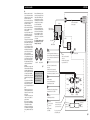
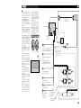
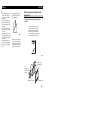
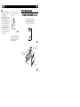
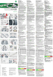
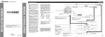
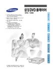
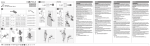
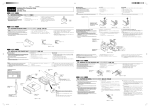
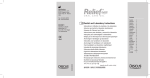
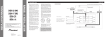
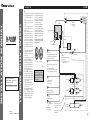
Connecting the Units
<ENGLISH>
• When an external power amp is being used with
this system, be sure not to connect the blue/white
lead to the amp’s power terminal. Likewise, do
not connect the blue lead to the power terminal of
the auto-antenna. Such connection could cause
excessive current drain and malfunction.
• To avoid a short-circuit, cover the disconnected
lead with insulating tape. Insulate the unused
speaker leads without fail. There is a possibility of
a short-circuit if the leads are not insulated.
• To prevent incorrect connection, the input side of
the IP-BUS connector is blue, and the output side
is black. Connect the connectors of the same colors correctly.
• This unit can not be installed in a vehicle that
does not have an ACC (accessory) position on
the ignition switch. (Fig. 1)
Power amp
(sold separately)
Subwoofer output or nonfading output
IP-BUS cable
Antenna jack
O
F
T
<YRD5033-A/U> ES
<KMINX> <04J00001>
Fuse
Multi-CD player
(sold separately)
O
Yellow/black
If you use an equipment with Mute function, wire this lead
to the Audio Mute lead on that equipment. If not, keep the
Audio Mute lead free of any connections.
STAR
STAR
ACC position
OF
OF
ACC
N
F
No ACC position
Fig. 1
• Cords for this product and those for other
products may be different colors even if they
have the same function. When connecting this
product to another product, refer to the supplied
manuals of both products and connect cords that
have the same function.
Blue
When the source is selected the tuner, a control signal is
output.
To Auto-antenna relay control terminal.
If the car features a glass antenna, connect to the antenna
booster power supply terminal (max. 300 mA 12 V DC).
System remote control
Blue/white
When the source is switched ON, a control
signal is output.
To system control terminal of the power amp
(max. 300 mA 12 V DC).
White
Yellow
To terminal always supplied
with power regardless of
ignition switch position.
Gray
+
+
≠
≠
Front speaker
Front speaker
White/black
Left
Red
To electric terminal controlled by
ignition switch (12 V DC) ON/OFF.
Green
Gray/black
Right
Violet
+
+
≠
≠
Rear speaker
Rear speaker
Green/black
Violet/black
Orange/white
To lighting switch terminal.
Black (ground)
To vehicle (metal) body.
This terminal may or
may not be included.
Printed in China
Connecting cords
with RCA pin plugs
(sold separately)
This Product
IP-BUS input (Blue)
N
This product conforms to new cord colors.
Los colores de los cables de este producto se conforman con un nuevo código de colores.
• This unit is for vehicles with a 12-volt battery and
negative grounding. Before installing it in a recreational vehicle, truck, or bus, check the battery
voltage.
• To avoid shorts in the electrical system, be sure to
disconnect the ≠ battery cable before beginning
installation.
• Refer to the owner’s manual for details on connecting the power amp and other units, then make
connections correctly.
• Secure the wiring with cable clamps or adhesive
tape. To protect the wiring, wrap adhesive tape
around them where they lie against metal parts.
• Route and secure all wiring so it cannot touch any
moving parts, such as the gear shift, handbrake,
and seat rails. Do not route wiring in places that
get hot, such as near the heater outlet. If the insulation of the wiring melts or gets torn, there is a
danger of the wiring short-circuiting to the vehicle
body.
• Don’t pass the yellow lead through a hole into the
engine compartment to connect to the battery.
This will damage the lead insulation and cause a
very dangerous short.
• Do not shorten any leads. If you do, the protection
circuit may fail to work when it should.
• Never feed power to other equipment by cutting
the insulation of the power supply lead of the unit
and tapping into the lead. The current capacity of
the lead will be exceeded, causing overheating.
• When replacing the fuse, be sure to only use a
fuse of the rating prescribed on this unit.
• Since a unique BPTL circuit is employed, never
wire so the speaker leads are directly grounded or
the left and right ≠ speaker leads are common.
• The black lead is ground. Please ground this lead
separately from the ground of high-current products such as power amps.
If you ground the products together and the
ground becomes detached, there is a risk of damage to the products or fire.
• Speakers connected to this unit must be highpower with minimum rating of 50 W and impedance of 4 to 8 ohms. Connecting speakers with
output and/or impedance values other than those
noted here may result in the speakers catching
fire, emitting smoke, or becoming damaged.
T
FH-P4200MP
INSTALLATION MANUAL
INSTALLATION MANUAL
Note:
With a 2 speaker system, do not connect
anything to the speaker leads that are not
connected to speakers.
Perform these connections when using
the optional amplifier.
Subwoofer or
Rear speaker
+
+
≠
≠
Subwoofer or
Rear speaker
Fig. 2
<ESPAÑOL>
Conexión de las unidades
Nota:
O
F
O
Salida de altavoz de graves
secundario o salida sin atenuación
Cable IP-BUS
Jack para antena
Fusible
Reproductor de
Multi-CD (en venta
por separado)
Entrada IP-BUS (Azul)
No en la posición ACC
T
Fig. 1
• Los cables para este producto y aquéllas para
otros productos pueden ser de colores diferentes
aun si tienen la misma función. Cuando se
conecta este producto a otro, refiérase a los
manuales de ambos productos y conecte los
cables que tienen la misma función.
Amplificador de
potencia (en venta
por separado)
Cables de conexión con clavjás RCA
(en venta por separado).
Este producto
Amarillo/negro
Si se utiliza un equipo con función de silenciamiento, conecte este
conductor con el conductor de silenciamiento de audio en tal equipo.
De lo contrario, mantenga el conductor de silenciamiento de audio
libre de conexiones.
STAR
STAR
Posición ACC
OF
ACC
T
F
N
OF
• Cuando se está utilizando un amperio de potencia
externa con este sistema, asegúrese de no conectar
el conductor azul/blanco al terminal de potencia
de amperios. Asimismo, no conecte el conductor
azul al terminal de potencia de la auto-antena. Tal
conexión podría causar la fuga de corriente excesiva y causar fallos de funcionamiento.
• Para evitar cortocircuitos, cubra o conductor
desconectado con cinta aislada. Aísle los conductores de altavoz no usados sin falta. Hay la posibilidad de cortocircuito si no se aíslan los conductores.
• Para evitar la conexión incorrecta, el lado de entrada del conector IP-BUS es azul, y el lado de
salida es negro. Conecte los conectores del mismo
color correctamente.
• No se puede instalar esta unidad en un vehículo
que no tenga una posición ACC (accesorio) en
el interruptor de encendido. (Fig. 1)
N
• Esta unidad es para vehículos con batería de 12
voltios y con conexión a tierra. Antes de instalar
la unidad en un vehículo recreativo, camioneta, o
autobús, revise el voltaje de la batería.
• Para evitar cortocircuitos en el sistema eléctrico,
asegúrese de desconectar el cable de la batería ≠
antes de comenzar con la instalación.
• Consulte con el manual del usuario para los
detalles sobre la conexión de la alimentación de
amperios y de otras unidades, luego haga las
conexiones correctamente.
• Asegure el cableado con abrazaderas de cables o
con cinta adhesiva. Para proteger el cableado,
envuélvalo con cinta adhesiva donde éstos se
apoyan sobre las piezas de metal.
• Coloque y asegure todo el cableado de tal manera
que no toque las piezas en movimiento, tal como
la palanca de cambio de velocidades, el freno de
mano, y los pasamanos de los asientos. No
coloque el cableado en lugares que se calientan,
tal como cerca de la salida de un calefactor. Si el
material aislante del cableado se derritiera o se
gastara, habrá el peligro de un cortocircuito del
cableado a la carrocería del vehículo.
• No pase el conductor amarillo a través de un orificio en el compartimiento del motor para conectar
a la batería. Esto dañará el material aislante del
conductor y causará un cortocircuito peligroso.
• No acorte ningún conductor. Si lo hiciera, la protección del circuito podría fallar al funcionar
cuando debería.
• Nunca alimente energía a otros equipos cortando
el aislamiento del conductor de alimentación provista de la unidad y haciendo un empalme con el
conductor. La capacidad de corriente del conductor se excederá, causando el recalentamiento.
• Cuando reemplace el fusible, asegúrese de utilizar
solamente un fusible del ratio especificado para esta
unidad.
• Ya que se emplea un circuito único BPTL, nunca
coloque los cables de manera que los conductores
del altavoz estén directamente en conexión a
tierra o que el altavoz izquierdo y derecho ≠ sean
comunes.
• El conductor negro es la masa. Conecte a masa
este conductor separadamente desde la masa de
los productos de alta corriente tal como los amplificadores de potencia.
Si conecta juntos a masa los productos y la masa
se desconecta, se crea el riesgo de daños a los
productos o de incendios.
• Los altavoces conectados a esta unidad deben ser
del tipo de alta potencia con un régimen mínimo de
50 W y una impedancia de 4 a 8 ohmios. La
conexión de altavoces con valores de impedancia
y/o de salida diferentes a los anotados aquí podrían
causar fuego, emisión de humo o daños a los altavoces.
Control remote de sistema
Azul/blanco
Cuando se conecta la fuente, una señal de
control se emite.
Al terminal de control de sistema del amp.
de potencia (máx. 300mA 12 V CC).
Azul
Cuando la fuente se elige al sintonizador, una señal de
control se emite.
Al terminal de control de relé de antena automática
Si el vehículo tiene una antena en vidrio, conecte al terminal de suministro de energía de la antena (máx. 300 mA 12 V CC).
Blanco
Amarillo
Al terminal con suministro
consante de electricidad, independientemete de
la posición del interruptor de encendido.
Altavoz
delantero
Gris
+
+
≠
≠
Blanco/negro
Izquierda
Verde
Rojo
Al terminal de energía eléctrica controlado por el interruptor
de encendido del vehículo (12 V CC.) ON/OFF.
Altavoz
trasero
+
Gris/negro
Violeta
Gris
≠
Derecha
+
≠
Verde/negro
Altavoz
delantero
Altavoz
trasero
Violeta/negro
Anaranjado/blanco
Al terminal de interruptor de iluminación.
Negro (masa)
A la carrocería del veículo
(parte metálica).
Puede que este terminal
esté o no incluido.
Con un sistema de 2 altavoces, no
conecte nada a los hilos de altavoz
que no se conectam a los altavoces.
Lleve a cabo estas conexiones cuando
utilice el amplificador opcional.
Altavoz de graves
secundario o
altavoz trasero
+
+
≠
≠
Altavoz de graves
secundario o
altavoz trasero
Fig. 2
<한글>
장치의 연결법
주의:
• 이 기기를 별도의 파워 앰프와 연결할 때, 청
색/백색 전선을 앰프의 전원 단자에 연결하지
않도록 주의하십시오. 또한 청색 전선을 자동
안테나 전원 단자에 연결하지 않도록 주의하십
시오. 이는 전원의 과도한 소모와 기기의 고
장을 초래할 수 있습니다.
• 단락을 막기 위해서 아무 것과도 연결되어 있
지 않은 전선의 선단부는 테이프로 감아 놓으
십시오. 사용하지 않는 스피커의 선은 반드시
테이프로 감아 놓으십시오. 감아 놓지않은 전
선들은 단락을 일으킬 가능성이 있습니다.
• IP-BUS 커넥터의 입력측은 청색에 연결되고 출
력측은 흑색에 연결되어야 합니다. 같은 색깔
의 커넥터끼리 연결하십시오.
• 본 기기는 시동 스위치에 ACC(액세사리) 위치가
없는 자동차에는 연결할 수 없습니다. (그림 1)
파워 앰프
(별도 판매)
전선들을 RCA 핀플러그
(별도 판매)로 연결하십시오.
본 제품
초저음 출력 혹은 무 페이딩 출력
IP-BUS 케이블
안테나 잭
퓨즈
멀티CD 플레이어
(별도 판매)
F
O
STAR
STAR
T
ACC 위치
OF
O
T
F
ACC
N
OF
IP-BUS 입력(청색)
N
• 본 제품은 음극 접지를 사용하는 12 볼트 축
전지가 있는 자동차를 기준으로 제작되었습니
다. 레저용 차량이나 버스, 트럭에 설치할 때
는 축전지 전압을 확인하십시오.
• 전기장치의 단락(短絡)을 막기 위해서 축전지
의 ≠ 케이블을 풀어놓고 설치하십시오.
• 파워 앰프 등의 연결에 대한 자세한 사항에
관하여 사용자 설명서를 읽으신 후 정확하게
연결하십시오.
• 전선연결을 확실히 하기 위해서 전선들이 연결
된 부분을 전선용 조임쇠나 접착테이프 등으로
연결하십시오. 전선이 금속에 부착되는 경우에
는 연결 부위를 접착테이프로 확실히 붙이십시
오.
• 연결된 전선들을 한쪽으로 잘 정리하여 변속기
나 주차브레이크 혹은 안전벨트에 걸리지 않게
정리하십시오. 그리고 전선들을 난방 방출구
같이 뜨거워지는 물건 가까이 닿지 않도록 정
리하십시오. 만약 전선의 단열피복이 녹거나
찢어지게 되면 전선의 단락이 차체의 누전으로
번질 위험이 있습니다.
• 노란색 전선을 엔진실로 가는 구멍을 통과시켜
축전지에 연결시키면 안됩니다. 이는 전선의
단열피복을 손상시켜 아주 위험한 단락을 일으
킵니다.
• 어느 전선이라도 짧게 줄이지 마십시오. 보호
회로가 필요할 때 작동하지 않을 우려가 있습
니다.
• 절대 전선을 벗겨내어 다른 기기의 전원 공급
선에 연결시켜 다른 기기에 전원을 공급하지
마십시오. 전선이 일정한 전류 용량을 과하면
과열됩니다.
• 퓨즈를 교환할 때에는 본 제품에 규정된 규격
퓨즈만을 사용하십시오.
• 이 제품은 특수 BPTL 회로를 사용하고 있기
때문에 스피커 도선을 접지시켜서는 안되며,
좌, 우 스피커의 ≠ 선이 공통으로 연결되어
서도 안됩니다.
• 흑색전선은 접지용입니다. 이 선은 파워 앰프
같은 다른 높은 전류기기의 접지선과는 별도로
연결해 주십시오.
만약 두 선을 같이 접지시켜서 접지부분이 이
탈될 경우 제품이 고장나거나 화재발생의 위험
이 있습니다.
• 연결될 스피커는 적어도 최소한 50 와트 이상
의 출력과 4~8 옴의 임피던스를 가지는 고출
력 사양이어야 됩니다. 이 사양에 못 미치는
스피커를 사용할 경우, 스피커에서 연기가 나
거나 불이 나든지 혹은 고장이 날 수 있습니
다.
바르지 않은 ACC 위치
그림 1
• 비록 같은 기능을 가지는 제품이라도 한 제품
의 전선과 다른 제품의 전선이 서로 다른 색깔
일 수가 있습니다. 본 제품을 다른 제품과 연
결시킬 경우에는 양 설명서를 다 참조하신 다
음 같은 기능을 가지는 전선끼리 연결하십시
오.
노란색/검정색
만약 Mute 기능을 가지는 기기를 사용할 경우, 그 기기의
Audio Mute 전선에 이 선을 연결하십시오. 그렇지 않을 경우
에는 Audio Mute 전선을 아예 연결하지 마십시오.
청색
입력소스로 튜너를 선택한 경우에는 통제용 신호음이
나옵니다.
자동안테나 계전기 단자에 연결하십시오.
유리 안테나를 가진 차량의 경우에는 안테나 증폭기
전원단자에 연결하십시오. (최대 300 mA 12 V DC)
청색/백색
입력소스가 켜져 있을 때에는 통제용
신호음이 출력이 됩니다.
파워 앰프의 시스템 통제 단자에 연결
하십시오.(최대 300 mA 12 V DC)
시스템 원격제어
백색
노란색
시동장치의 시동의 여부와 관계없이
전류가 공급되는 단자에 연결하십시오.
회색
+
+
≠
≠
전면 스피커
전면 스피커
백색/검정색
좌측
빨간색
시동장치의 스위치(ON/OFF)로
조정되는 전원단자(12 V DC)에 연결하십시오.
녹색
회색/검정색
우측
보라색
+
+
≠
≠
후면 스피커
후면 스피커
녹색/검정색
보라색/검정색
오렌지색/백색
조명 스위치 단자에 연결하십시오.
검정색(접지)
자동차 금속 차체에 연결.
이 단자는 포함되어 있지
않는 경우도 있습니다.
2 스피커 시스템일 경우 스피커와
연결하고 남은 전선들은 다른 어느
것과도 연결하지 마십시오.
초저음 스피커
혹은 후면 스피커
+
+
≠
≠
초저음 스피커
혹은 후면 스피커
이 연결방식은 옵션의 앰프와
연결할 때에 사용하십시오.
그림 2
Installation
<ENGLISH>
Note:
• Before making a final installation of the unit, temporarily connect the wiring to confirm that the
connections are correct and the system works
properly.
• Use only the parts included with the unit to ensure
proper installation. The use of unauthorized parts
can cause malfunctions.
• Consult with your nearest dealer if installation
requires the drilling of holes or other modifications of the vehicle.
• Install the unit where it does not get in the driver’s
way and cannot injure the passenger if there is a
sudden stop, like an emergency stop.
• The semiconductor laser will be damaged if it
overheats, so don’t install the unit anywhere hot
— for instance, near a heater outlet.
• If installation angle exceeds 30° from horizontal,
the unit might not give its optimum performance.
(Fig. 3)
Installation using the screw holes on the side of the unit
Fastening the unit to the factory radio mounting bracket. (Fig. 4) (Fig. 5)
Select a position where the screw holes of the bracket and
the screw holes of the head unit become aligned (are fitted), and tighten the screws at 3 or 4 places on each side.
Use either binding screws (5 × 8 mm) or flush surface
screws (5 × 8 mm), depending on the shape of the screw
holes in the bracket.
30˚
Fig. 3
• When installing, to ensure proper heat dispersal
when using this unit, make sure you leave ample
space behind the rear panel and wrap any loose
cables so they are not blocking the vents.
Fig. 4
If the pawl gets in the
way, bend it down.
Screw
Be sure to use the screws
supplied with this product.
Factory radio mounting bracket
Dashboard or Console
Fig. 5
<ESPAÑOL>
Instalación
Nota:
• Antes de finalmente instalar la unidad, conecte el
cableado temporalmente y compruebe que las
conexiones están correctas e que el sistema funciona debidamente.
• Utilice sólo las piezas que se incluyen con esta
unidad para asegurar la instalación adecuada. El
uso de piezas no autorizadas podría causar fallos
de funcionamiento.
• Consulte con su distribuidor si la instalación
requiere del taladro de orificios u otras modificaciones del vehículo.
• Instale la unidad donde no alcance el espacio del
conductor, y donde no pueda dañar a los pasajeros
si sucediera un paro repentino, como una detención de emergencia.
• El semiconductor láser se dañará si se sobrecalienta, por eso no instale la unidad en un lugar
caliente – por ejemplo, cerca de la salida de un
calefactor.
• Si el ángulo de la instalación excede los 30° del
lado horizontal, la unidad podría no brindar su
óptimo funcionamiento. (Fig. 3)
Instalación usando los agujeros para tornillos ubicados en ambos
costados de la unidad
Fijación de esta unidad a la ménsula de montaje de radio de fábrica.
(Fig. 4) (Fig. 5)
30˚
Fig. 3
Seleccione una posición en donde los orificios roscados de
la ménsula y los orificios roscados de la unidad cabezal
queden alineados (ajustados) y apriete los tornillos en 3 o 4
lugares de cada lado. Utilice ya sea los tornillos de fijación
(5 × 8 mm) o los tornillos a paño (5 × 8 mm), dependiendo
de la forma de los orificios de tornillo en la ménsula.
• Cuando instale, para asegurar la dispersión apropiada del calor cuando utilice la unidad, asegúrese
de dejar un amplio espacio detrás del panel trasero
y de enrollar cualesquiera cables sueltos de modo
que no bloqueen las aberturas de ventilación.
Fig. 4
Si el linguete se pone en el
camino, dóblelo hacia abajo.
Tornillo
Asegúrese de utilizar los
tornillos suministrados con
este producto.
Ménsula de montaje de radio existente
Tablero de instrumentos o consola
Fig. 5
설치 방법
<한글>
주의 :
• 본 기기를 최종 설치하기 전에, 전선이 제대로
연결되었고 제품이 잘 작동하는지 확인하기 위
해 임시로 연결해 보십시오.
• 정확한 작동을 위해서 제품을 구입할 때에는
제공된 부품들만 사용하여 주십시오. 비지정
부품을 쓰면 작동불량을 초래할 수 있습니다.
• 본 기기를 설치하기 위해 드릴로 구멍을 뚫을
필요가 있거나 차량에 조작을 해야 할 경우에
는 근처의 지정 대리점에 연락을 하십시오.
• 운전자의 방해가 되지 않고 급정거 시 탑승자가
다치지 않도록 장소를 가려서 설치하십시오.
• 반도체 레이저는 과열 시 고장이 날 수 있습니
다. 그러므로 난방 방출구 같이 뜨거운 곳 근
처에 설치하지 마십시오.
• 설치 각도가 수평으로부터 30°이상이 되면 본
제품은 최적의 성능을 발휘하지 못할 수도 있
습니다. (그림 3)
기기 측면의 나사구멍을 이용한 설치 방법
기기를 기존 라디오 부착 브랙킷에 고정시키는 방법. (그림 4) (그림 5)
브래킷의 나사구멍들을 헤드유닛의 나사구멍들과 일직
선으로 맞추고, 양쪽에서 3, 4개 정도의 나사들을 조입
니다. 브래킷의 나사구멍의 형태에 따라 바인딩 나사
(5 × 8 mm) 나 평면 나사(5 × 8 mm)를 사용하십시오.
30˚
그림 3
• 이 기기를 사용하는 동안 열이 충분히 분산되
도록, 설치할 때에, 반드시 뒷면 패널 뒤쪽에
충분한 공간을 남겨두고, 늘어진 케이블이 통
풍구를 막지 않도록 묶으십시오.
그림 4
만약 멈춤쇠가 걸린다면
아래쪽으로 구부리십시오.
나사
본 제품과 함께 제공된
나사만 사용하십시오.
기존 라디오 부착 브래킷
계기반이나 조종대
그림 5