1
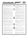
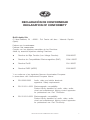
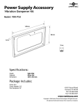
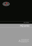
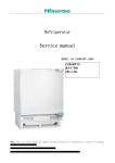
User’s Manual
vantec active series
Antes de utilizar el equipo, lea la sección
“Precauciones de seguridad” de este manual.
Conserve este manual para futuras consultas.
Before operating the device, please read the
“Safety precautions” section of this manual.
Retain this manual for future reference.
CONTENTS
SAFETY PRECAUTIONS
3
WARRANTY
4
DECLARATION OF CONFORMITY
5
INTRODUCTION
6
7 - 13
CONFIGURATIONS
2 x vantec 12A (wireless audio)
2 x vantec 12A
2 x vantec 15A
2 x vantec 12A (vantec 15A)+ 1 x vantec 18A
2 x vantec 15A (vantec 12A) + 2 x vantec18A
2 x vantec 15A (vantec 12A) + 1 x vantec 18A+ 1 x DSP
2 x vantec 215A + 2 x vantec 18A
LINE DRAWINGS
14 - 15
SPECIFICATIONS
15
16 - 24
AMPLIFIER
Description
ON / OFF
Overload indicators
Equalisation
Overheating
Low mains voltage
Current consumption
Troubleshooting
25 - 26
RIGGING SYSTEM
27
APPENDIX
Line connections: unbalanced and balanced
Manual del Usuario / vantec active / User’s Manual
vantec active series
Precauciones de Seguridad
Safety Precautions
Cajas acústicas activas / Self-powered loudspeaker enclosures
El signo de exclamación dentro de un triángulo indica la
existencia de importantes instrucciones de operación y
mantenimiento en la documentación que acompaña al producto.
Conserve y lea todas estas instrucciones. Siga las advertencias.
ATENCIÓN: Es un producto clase A, por lo que en entornos
domésticos puede causar radio-interferencias, en cuyo caso el
usuario tendrá que tomar las medidas oportunas.
De acuerdo con EN55103-2, usar el equipo sólo en entornos E1,
E2, E3 ó E4.
The exclamation point inside an equilateral triangle is intend to
alert the users to the presence of important operating and
maintenance
(servicing)
instructions
in
the
literature
accompanying the product. Heed all warnings. Follow all
instructions. Keep these instructions.
WARNING: This is a class A product. In a domestic environment
this product may cause radio interferences in which case the
user may be required to take adequate measures.
Use this product only in E1, E2, E3 or E4 environments
according to EN55103-2.
Do not remove mains connector ground, it is dangereous and
illegal. Class I device.
No desconecte la tierra en el conector de alimentación pues es
peligroso e ilegal. Equipo de Clase I.
El signo del rayo con la punta de flecha, alerta contra la
presencia de voltajes peligrosos no aislados. Para reducir el
riesgo de choque eléctrico, no retire la cubierta.
Sólo use este equipo con el cable de red de alimentación
adecuado para su país.
No instale el aparato cerca de ninguna fuente de calor como
radiadores, estufas u otros aparatos que produzcan calor. Debe
instalarse siempre sin bloquear la libre circulación de aire por las
aletas del radiador.
Si los altavoces action se utilizan al aire libre en un día soleado,
colocar los altavoces en un área sombreada o a cubierto. Los
amplificadores de los altavoces tienen circuitos de protección
que silenciarán temporalmente el altavoz cuando las
temperaturas que se alcanzan sean extremadamente altas. Esto
puede suceder en los días calurosos cuando el altavoz esté
expuesto a la luz solar directa.
No exponga este equipo a la lluvia o humedad. No use este
aparato cerca del agua (piscinas y fuentes, por ejemplo). No
exponga el equipo a salpicaduras ni coloque sobre él objetos
que contengan líquidos, tales como vasos y botellas. Equipo IP20.
Este símbolo indica que el presente producto no puede ser
tratado como residuo doméstico normal, sino que debe
entregarse en el correspondiente punto de recogida de equipos
eléctricos y electrónicos.
Equipo diseñado para funcionar entre 15ºC y 42ºC con una
humedad relativa máxima del 95%, con un rango de ±10% de la
tensión nominal de alimentación indicada en la etiqueta trasera
(según IEC 60065:2001). Si debe sustituir el fusible preste
atención al tipo y rango.
The lightning and arrowhead symbol warns about the presence
of uninsulated dangerous voltage. To reduce the risk of electric
shock, do not remove the cover.
Only use this equipment with an appropriate mains cord for your
country.
Do not install near any heat sources such as radiators, heat
registers, stoves or other apparatus that produce heat. The
circulation of air through the heatsink must not be blocked.
If action loudspeakers are used outdoors on a sunny day, place
the loudspeakers in a shaded or covered area. The loudspeaker
amplifiers have protection circuits that temporarily shut the
loudspeaker off when extremely high temperatures are reached.
This can happen on hot days when the loudspeaker is in direct
sunlight.
Do not expose this device to rain or moisture. Do not use this
apparatus near water (for example, swimming pools and
fountains). Do not place any objects containing liquids, such as
bottles or glasses, on the top of the unit. Do not splash liquids
on the unit. IP-20 equipment.
This symbol on the product indicates that this product should
not be treated as household waste. Instead it shall be handed
over to the appicable collection point for the recycling of
electrical and electronic equipment.
Working temperature ranges from 15ºC to 42ºC with a relative
humidity of 95%, with ±10% of the rated main voltage value
indicated on the rear label (according to IEC 60065:2001). If the
fuse needs to be replaced, please pay attention to correct type
and ratings.
El cableado exterior conectado al equipo requiere de su
instalación por una persona instruida o el uso de cables flexibles
ya preparados.
Si el aparato es conectado permanentemente, la instalación
eléctrica del edificio debe incorporar un interruptor multipolar con
separación de contacto de al menos 3mm en cada polo.
The outer wiring connected to the device requires installation by
an instructed person or the use of a flexible cable already
prepared.
If the apparatus is connected permanently, the electrical system
of the building must incorporate a multipolar switch with a
separation of contact of at least 3mm in each pole.
Desconecte este aparato durante tormentas eléctricas,
terremotos o cuando no se vaya a emplear durante largos
periodos.
Unplug this apparatus during lightning storms, earthquakes or
when unused for long periods of time.
No emplace altavoces en proximidad a equipos sensibles a
campos magnéticos, tales como monitores de televisión o
material magnético de almacenamiento de datos.
Do not place loudspeakers in proximity to devices sensitive to
magnetic fields such as television monitors or data storage
magnetic material.
Para las cajas con vaso para trípode, la altura máxima de
seguridad desde el suelo a la base de la caja montada sobre
trípode modelo TRD-2, con pies a 55 cm del eje del trípode, es:
For enclosures with tripod socket, the maximum safety height
from floor to bottom of enclosure when mounting on a TRD-2
tripod, with legs spread 55cm from the central pole, is:
vantec 12A ------------->115 cm
vantec 15A ------------->105 cm
vantec 12A ------------->115 cm
vantec 15A ------------->105 cm
El colgado del equipo sólo debe realizarse utilizando los herrajes
de colgado recomendados y por personal cualificado. No
cuelgue la caja de las asas.
No existen partes ajustables por el usuario en el interior de este
equipo. Cualquier operación de mantenimiento o reparación
debe ser realizada por personal cualificado. Es necesario el
servicio técnico cuando el equipo se haya dañado de alguna
forma, como que haya caído líquido o algún objeto en el interior
del aparato, haya sido expuesto a lluvia o humedad, no funcione
correctamente, haya recibido un golpe o su cable de red esté
dañado.
Limpie con un paño seco. No use limpiadores con disolventes.
La reventa del producto sólo es posible incluyendo el manual de
usuario. Cualquier cambio producido en el producto tiene que
ser documentado por escrito y aprobado por el comprador en el
momento de la reventa.
55 cm
The appliance should be flown only from the rigging points and
by qualified personnel. Do not suspend the box from the
handles.
No user serviceable parts inside. Refer all servicing to qualified
service personnel. Servicing is required when the apparatus has
been damaged in any way, such as power-supply cord or plug is
damaged, liquid has been spilled or objects have fallen into the
apparatus, the apparatus has been exposed to rain or moisture,
does not operate normally or has been dropped.
Clean only with a dry cloth. Do not use any solvent based
cleaners.
Reselling of the product is only possible if the user manual is
aviable. Any changes made to the product have to be
documented in writing and passed on to the buyer in the event
of resale.
Manual del Usuario / vantec active / User’s Manual
3
GARANTÍA
Todos nuestros productos están garantizados por un periodo de 24
meses desde la fecha de compra.
Las garantías sólo serán válidas si son por un defecto de
fabricación y en ningún caso por un uso incorrecto del producto.
Las reparaciones en garantía pueden ser realizadas,
exclusivamente, por el fabricante o el servicio de asistencia técnica
autorizado.
Otros cargos como portes y seguros, son a cargo del comprador
en todos los casos.
Para solicitar reparación en garantía es imprescindible que el
producto no haya sido previamente manipulado e incluir una
fotocopia de la factura de compra.
WARRANTY
All D.A.S. products are warrantied against any manufacturing defect
for a period of 2 years from date of purchase.
The warranty excludes damage from incorrect use of the product.
All warranty repairs must be exclusively undertaken by the factory
or any of its authorised service centers.
To claim a warranty repair, do not open or intend to repair the
product.
Return the damaged unit, at shippers risk and freight prepaid, to
the nearest service center with a copy of the purchase invoice.
4
Manual del Usuario / vantec active / User’s Manual
DECLARACIÓN DE CONFORMIDAD
DECLARATION OF CONFORMITY
D.A.S. Audio, S.A.
C/ Islas Baleares, 24 - 46988 - Pol. Fuente del Jarro - Valencia. España
(Spain).
Declara que la serie vantec:
Declares that vantec series:
Cumple con los objetivos esenciales de las Directivas:
Abide by essential objectives relating Directives:
l
Directiva de Baja Tensión (Low Voltage Directive)
2006/95/CE
l
Directiva de Compatibilidad Electromagnética (EMC)
2004/108/CE
l
Directiva RoHS
2011/65/CE
l
Directiva RAEE (WEEE)
2002/96/CE
Y es conforme a las siguientes Normas Armonizadas Europeas:
In accordance with Harmonized European Norms:
l
EN 60065:2002
Audio, video and similar electronic
apparatus. Safety requirements.
l
EN 55103-1:2009 Electromagnetic compatibility.
Product family standard for audio, video, audiovisual and entertainment lighting control apparatus
for professional use. Part 1:Emission.
l
EN 55103-2:2009 Electromagnetic compatibility.
Product family standard for audio, video, audiovisual and entertainment lighting control apparatus
for professional use. Part 2:Immunity.
Manual del Usuario / vantec active / User’s Manual
5
INTRODUCTION
The vantec series inherits the exceptional sound quality and rugged build that have made D.A.S.
professional systems an internacional sound reinforcement standard. Designed from “real-world” experience,
they offer users outstanding performance, absolute reliability, and unparalleled convenience. Whether it is in a
high-profile venue or on the stage of a major event, the vantec series will provide the power and definition
needed to make your performance a success.
Features
vantec 12A
-Two-way powered system.
-12” bass loudspeaker.
-Compression driver with titanium diaphragm.
-Symmetric enclosure design for stage monitor use.
-Built-in rigging points (eyebolt based).
-Stand mountable / Dual angle.
The vantec 12A is a powered loudspeaker (2 channel Class D amplifier), that utilizes a
12” low frequency transducer and a 1” exit compression driver. The multi-angle
cabinet is constructed of Birch plywood protected by an environmentally friendly black
paint finish. Two bar handles and a steel grille are provided. A 35mm tripod socket
allows for stand mounting with two possible angles 0º or -10º.
vantec 15A
-Two-way powered system.
-15” bass loudspeaker.
-Compression driver with titanium diaphragm.
-Symmetric enclosure design for stage monitor use.
-Built-in rigging points (eyebolt based).
-Stand mountable.
The vantec 15A is a powered loudspeaker (2 channel Class D amplifier), that utilizes a
15” low frequency transducer and a 1” exit compression driver. The multi-angle
cabinet is constructed of Birch plywood protected by an environmentally friendly black
paint finish. Two bar handles and a steel grille are provided. A 35mm tripod socket
allows for stand mounting with two possible angles 0º or -10º.
vantec 215A
-3-way powered system
-2 x 15" bass loudspeaker working in a “dual band” configuration (2.5 ways)
-Compression driver with titanium diaphragm
-Two steel-reinforced handles
The vantec 215A is a powered loudspeaker (3 channel Class D amplifier), that
utilizes two 15” bass loudspeakers for extra low frequency punch and higher SPL in a
“dual band” configuration where each speaker works in a specific frequency range.
High frequencies are handled by a 1”exit compression driver with titanium diaphragm.
The trapezoidal cabinet is constructed using Birch plywood and protected with a hardwearing black paint finish. Two bar handles and a steel grille sealed against corrosion
using a polyamide powder coat finish are provided. Rigging points provide a safe and
simple way to fly the action 215A cabinets.
vantec 18A
-Bass-reflex powered subwoofer system
-18" low frequency transducer
-Precise and powerful bass reproduction
-Top located pole mount socket
The vantec 18A bass powered system (Class D amplifier) incorporates a 18” low
frequency transducer with a 4 " voice coil mounted as a direct radiator into a bassreflex cabinet. The loudspeaker is protected by a perforated steel grille, sealed against
corrosion using a powder coat finish. The vantec 18A is designed for use in biamped
systems. A top located pole-mount socket permits mounting full-range systems above
the vantec 18A and two bar handles makes moving easy.
6
Manual del Usuario / vantec active / User’s Manual
CONFIGURATIONS
Vantec 12A
Max distance 20m (65 ft)
Vantec 12A
Max distance 20m (65 ft)
wireless
audio source
TRD-2
TRD-2
master cabinet
(left channel)
slave cabinet
(right channel)
Wireless audio - master cabinet
Wireless audio - slave cabinet
wireless audio
input volume control
VANTEC 12A
VANTEC 12A
LINE
CH 1
0
MIC
LINE
CH 2
0
0
MIC
0
CH 1
MIX
CH 2
www.dasaudio.com
-oo
MAX
-oo
-oo
MAX
-oo
AUX IN
OUTPUT
INPUT 1
INPUT 2
Manual del Usuario / vantec active / User’s Manual
7
CONFIGURATIONS (cont´d)
Vantec 12A
Vantec 12A
TRD-2
TRD-2
L
VANTEC 12A
LINE
CH 1
0
MIC
LINE
CH 2
0
R
Mixer
VANTEC 12A
0
MIC
0
CH 1
MIX
CH 2
www.dasaudio.com
-oo
MAX
-oo
-oo
MAX
AUX IN
OUTPUT
8
INPUT 1
INPUT 2
Manual del Usuario / vantec active / User’s Manual
-oo
CONFIGURATIONS (cont´d)
Vantec 15A
Vantec 15A
TRD-2
TRD-2
L
R
Mixer
VANTEC 15A
VANTEC 15A
LINE
CH 1
0
MIC
LINE
CH 2
0
0
MIC
0
CH 1
MIX
CH 2
www.dasaudio.com
-oo
MAX
-oo
-oo
MAX
-oo
AUX IN
OUTPUT
INPUT 1
INPUT 2
Manual del Usuario /vantec active / User’s Manual
9
CONFIGURATIONS (cont´d)
Vantec 15A (or Vantec 12A)
Vantec 15A (or Vantec 12A)
Vantec 18A
TRD-2
TRD-2
L
R
Mixer
Set High Pass Filter to vantec 18A
VANTEC 18A
D.A.S. AUDIO S.A. (Valencia)
MADE IN SPAIN
HPF: V18A
LIMIT
LEVEL
0
LOW-PASS
100Hz
SIGNAL
Set Low Pass Filter at 100Hz
ON
VANTEC 15A
-oo
+6
80Hz
125Hz
www.dasaudio.com
POLARITY
LINE
CH 1
0
MIC
LINE
CH 2
0
+
PRESET
DEEP/LOUD
MIC
OUTPUT A
OUTPUT B
CH 1
MIX
CH 2
www.dasaudio.com
-oo
MAX
-oo
Use Left and Right Satellite Outputs
MAX
AUX IN
SATELLITE X-OVER
HPF/THRU
INPUT B
Do not press HPF satellite X-over
CAUTION
INPUT 2
RISK OF ELECTRIC SHOCK
DO NOT OPEN
INPUT 1
DO NOT EXPOSE THIS EQUIPMENT
TO RAIN OR MOISTURE
OUTPUT
INPUT A
AC INPUT
115/230 V~ 50/60Hz 390W
10
MAX. 8@230V / 3@115V
UNITS VANTEC 18A
Manual del Usuario / vantec active / User’s Manual
CONFIGURATIONS (cont’d)
Vantec 15A (or Vantec 12A)
Vantec 15A (or Vantec 12A)
L
TRD-6
R
TRD-6
Mixer
Vantec 18A
Vantec 18A
Set High Pass Filter to vantec 18A
VANTEC 18A
D.A.S. AUDIO S.A. (Valencia)
MADE IN SPAIN
HPF: V18A
LIMIT
LEVEL
0
LOW-PASS
100Hz
SIGNAL
ON
VANTEC 15A
-oo
+6
80Hz
POLARITY
LINE
CH 1
0
MIC
LINE
CH 2
0
PRESET
+
DEEP/LOUD
OUTPUT A
MIC
OUTPUT B
Use Left and Right Satellite Outputs
-oo
MAX
AUX IN
INPUT 1
SATELLITE X-OVER
HPF/THRU
Do not press HPF satellite X-over
INPUT 2
INPUT B
CAUTION
MAX
RISK OF ELECTRIC SHOCK
DO NOT OPEN
-oo
DO NOT EXPOSE THIS EQUIPMENT
TO RAIN OR MOISTURE
CH 1
MIX
CH 2
www.dasaudio.com
OUTPUT
Set Low Pass Filter at 100Hz
125Hz
www.dasaudio.com
INPUT A
AC INPUT
115/230 V~ 50/60Hz 390W
MAX. 8@230V / 3@115V
UNITS VANTEC 18A
Manual del Usuario / vantec active / User’s Manual
11
CONFIGURATIONS (cont’d)
VANTEC 18A
Vantec 18A
Caution
D.A.S. AUDIO S.A. (Valencia)
MADE IN SPAIN
LIMIT
LEVEL
0
LOW-PASS
100Hz
SIGNAL
ON
When using a external DSP the High Pass
filter for the top cabinets and the Low pass
filter in the subwoofer have to be set up in the
processor.
-oo
+6
80Hz
Set Low Pass Filter to
maximum position
125Hz
www.dasaudio.com
POLARITY
-
+
PRESET
DEEP/LOUD
OUTPUT A
This means that HPF needs to be off in
vantec 12A (15A) and Low Pass filter in the
sub at the maximum position.
OUTPUT B
It would be extremely important to time align
the system.
CAUTION
RISK OF ELECTRIC SHOCK
DO NOT OPEN
INPUT B
DO NOT EXPOSE THIS EQUIPMENT
TO RAIN OR MOISTURE
SATELLITE X-OVER
HPF/THRU
INPUT A
AC INPUT
115/230 V~ 50/60Hz 390W
MAX. 8@230V / 3@115V
UNITS VANTEC 18A
TRD-2
TRD-2
L
R
Mixer
Set HPF to off
Set HPF to off
HPF: off
HPF: off
VANTEC 15A
VANTEC 12A
LINE
CH 1
0
MIC
LINE
CH 2
0
0
MIC
0
CH 1
MIX
CH 2
www.dasaudio.com
-oo
MAX
-oo
-oo
MAX
AUX IN
OUTPUT
12
INPUT 1
INPUT 2
Manual del Usuario / vantec active / User’s Manual
-oo
CONFIGURATIONS (cont’d)
Set High Pass Filter to vantec 18A
HPF: V18A
VANTEC 215A
Vantec 215A
Vantec 215A
0
0
-oo
Vantec 18A
-oo
L
R
Vantec 18A
Mixer
VANTEC 18A
0
100Hz
-oo
+6
80Hz
www.dasaudio.com
-
125Hz
Set Low Pass Filter at 100Hz
+
Use Left and Right Satellite Outputs
Do not press HPF satellite X-over
115/230 V~ 50/60Hz 390W
Manual del Usuario / vantec active / User’s Manual
13
vantec 215A
vantec 15A
vantec 12A
LINE DRAWINGS
14
Manual del Usuario / vantec active / User’s Manual
vantec 18A
SPECIFICATIONS
Model
Power Amplifier
Input Type
Input Impedance
Sensitivity
Frequency Range (-10 dB)
HF Horn Coverage Angles (-6 dB)
Maximum Peak SPL at 1m
Transducers/ Replacement Parts
Wireless Audio
Enclosure Material
Color/Finish
Connectors
AC Power Requeriments
Dimensions (H x W x D)
Weight
Accessories
vantec 12A
vantec 15A
vantec 215A
vantec 18A
1500 W
(Class D Bi-amplified)
1500 W
(Class D Bi-amplified)
2250 W
(Class D Tri-amplified)
1500 W
(Class D mono amplified)
Balanced Differential Line
Line: 20 kohms
Line: 3V (+12dBu)
60 Hz - 20 kHz
Balanced Differential Line
Line: 20 kohms
Line: 3V (+12dBu)
45 Hz - 20 kHz
Balanced Differential Line
Line: 20 kohms
Line: 3V (+12dBu)
40 Hz - 20 kHz
90º x 50º
135 dB
LF: 12F4 / GM 12F4
HF: M-28 / GM M-28
Yes
Birch Plywood
Black ISO-flex Paint
INPUT: Female XLR
1/8" mini jack (3.5mm) Aux input
LOOP THRU: Male XLR
AC INPUT: PowerCon NAC 3 FCA
115V, 2.4A, 50 Hz / 60 Hz
230V, 1.2A, 50 Hz / 60 Hz
61 x 38 x 37.5 cm
24 x 15 x 14.8 in
21 kg (46.2 lb)
ANL-2 Eye Bolt
TRD-2 Speaker Stand
TRD-6 Pole Mount
90º x 50º
135 dB
LF: 15F4 / GM 15F4
HF: M-28 / GM M-28
Yes
Birch Plywood
Black ISO-flex Paint
INPUT: Female XLR
1/8" mini jack (3.5mm) Aux input
LOOP THRU: Male XLR
AC INPUT: PowerCon NAC 3 FCA
115V, 3A, 50 Hz / 60 Hz
230V, 1.5A, 50 Hz / 60 Hz
71 x 44.4 x 37.5 cm
28 x 17.5 x 14.8 in
24 kg (52.8 lb)
ANL-2 Eye Bolt
TRD-2 Speaker Stand
TRD-6 Pole Mount
90º x 50º
138 dB
LF: 2 x 15F4 / GM 15F4
HF: M-28 / GM M-28
Yes
Birch Plywood
Black ISO-flex Paint
INPUT: Female XLR
1/8" mini jack (3.5mm) Aux input
LOOP THRU: Male XLR
AC INPUT: PowerCon NAC 3 FCA
115V, 3A, 50 Hz / 60 Hz
230V, 1.5A, 50 Hz / 60 Hz
108 x 44.4 x 50.2 cm
42.5 x 17.5 x 19.8 in
41 kg (90.2 lb)
ANL-2 Eye Bolt
Balanced Differential Line
Line: 20 kohms
Line: 1.95V (+8dBu)
Loud: 35 Hz - 125 Hz
Deep: 30Hz - 125Hz
90º x 50º
135 dB
LF: 18LX / GM 18LX
No
Birch Plywood
Black ISO-flex Paint
INPUT: Female XLR
LOOP THRU: Male XLR
AC INPUT: PowerCon NAC 3 FCA
115V, 3A, 50 Hz / 60 Hz
230V, 1.5A, 50 Hz / 60 Hz
71 x 44.4 x 37.5 cm
28 x 17.5 x 14.8 in
24 kg (52.8 lb)
ANL-2 Eye Bolt
TRD-6 Pole Mount
D.A.S. Audio S.A. continuously strives to enhance its products through investigation and development. All
specifications are subject to change without prior warning.
Manual del Usuario / vantec active / User’s Manual
15
AMPLIFIER
Description: Vantec 12A/15A/215A
1) MASTER VOLUMEN AND DSP CONTROL:
Use the encoder to select the desired output volume and push/hold it to access to the different DSP and
cabinet settings.
2) MAIN SCREEN:
In the main screen all selected parameters and settings are shown. Besides this, there are two input level
indicators on the left , one output level indicator on the right and the center area is reserved to display
messages as Input Clip or Limit.
3) INPUT connectors :
1/4” Jack+XLR combined socket-type input signal connectors. This is a balanced connector just like the
LOOP THRU connector with the following pin assignments:
1 or S =GND (ground).
2 or T =(+) Non inverted input.
3 or R =(-) Inverted input.
4) OUTPUT
XLR-type output signal connector for connecting several units together and sending them all the same
signal.The user can select the signal going out; can be Ch1, Ch2 or MIX (see 6).
5) INPUT GAIN CONTROL:
For channels 1, 2 and AUX IN, gain control, line and microphone.
Note: Wireless Audio Signal is controlled with gain knob 1.
6) OUTPUT mix selector:
It allows the user to select which input channel signal to be sent to other cabinets. User can select Ch1, Ch2 or
both (Mix).
7) AUX in:
3.5 mm audio jack input for connecting external audio media devices, such as MP3 players. The input source
is controlled with Gain control 1.
2
1
+ 0 dB
0,0m
1 2
live
off
O
AUX IN
VANTEC 12A
5
WIRELESS
AUDIO
INPUT GAIN CONTROL
INPUT 1
CH 1
AD
5
0
0
MASTER VOLUME
INPUT 2
CH 2
AD
www.dasaudio.com
CH 1
OUTPUT
6
-oo
7
-oo
MIX
CH 2
6
MIX OUT
4
Block diagram of Mixer
(only Vantec 12/15/215A)
3
3
Vantec 12/15/215A
16
Manual del Usuario / vantec active / User’s Manual
By scrolling down the encoder more options
appear:
ADJUSTING THE LEVELS:
By default the state of the screen is the following:
MAIN MENU
MAIN MENU
Delay: 0,0m
LOW: 0 dB
EXPANDER: off
MID: 0 dB
+ 0 dB
WIRELESS AUDIO
HIGH: 0 dB
0,0m
live
1 2
off
MAIN MENU
O
WIRELESS AUDIO
Once the input source (s) have been connected to
the amplifier´s cabinet, the user has to adjust the
levels.
For the two input channels (1 and 2), two
independent gain controls are available. Be careful
when setting the input volume and do not exceed
the maximum level shown on the meters: (input clip
shown on channel one)
C
INPUT
CLIP
0,0m
peak
meters
Exceeding the limits may
cause speaker failure!!
live
1 2
off
live
off
PRESETS:
Five factory settings (live, dance, vocals, bboost,
monitor) depending on the type of music/use that
has been configured inside the unit:
+ 0 dB
0,0m
live
1 2
O
off
O
live preset
With the encoder go to Preset Sub-menu and press
the knob to access to the different options:
MAIN MENU
BACK
L
PRESET: Live
Exceeding the limits may
cause speaker failure!!
0,0m
1 2
BACK
rms
meter
After having set the input volume values under
the maximum level, user has to adjust ouput
volume with the master control. The level is shown
in the right meter of the screen. As with the inputs be
careful not exceeding the limit: (LIMIT shown)
LIMIT
OPTIONS
HPF: Off
MAIN MENU
O
DAS Audio SA
LogChirp - Frequency Response
15-07-2015 12,24,23
120,0
dBSPL
After these two volume adjustments the screen
will show something like this (when having the input
sources ON):
- 4 dB
0,0m
1 2
live
off
O
It is highly recommendable
working with output volume
below 0dB. If maximum
level is required user
should increase the output
level (higher than 0dB)
MAIN MENU:
BACK
110,0
100,0
PRESET:
Live >
90,0
80,0
HPF: Off
70,0
20
CH A
50
dBSPL
1/3 Octave
100
192kHz
200
32K
500
Rectangular
Start 0,00ms
1k
2k
Stop 170,66ms
Hz
5k
FreqLO 5,86Hz
10k
20k
Length 170,66ms
File: spl 1m -13 dBu monitor.mls
MAIN MENU
DAS Audio SA
LogChirp - Frequency Response
15-07-2015 12,24,23
120,0
dBSPL
BACK
110,0
100,0
PRESET:
<dance>
90,0
80,0
HPF: Off
70,0
20
CH A
50
dBSPL
1/3 Octave
100
192kHz
200
32K
500
Rectangular
Start 0,00ms
1k
2k
Stop 170,66ms
Hz
5k
FreqLO 5,86Hz
10k
20k
Length 170,66ms
File: spl 1m -13 dBu monitor.mls
MAIN MENU
DAS Audio SA
LogChirp - Frequency Response
15-07-2015 12,24,23
120,0
As stated previously by pushing the encoder the
user can access to the following options in the
MENU:
dBSPL
BACK
110,0
100,0
PRESET:
<vocals>
90,0
80,0
HPF: Off
MAIN MENU
BACK
MAIN MENU
PRESET: Live
BACK
70,0
20
CH A
50
dBSPL
1/3 Octave
100
192kHz
200
32K
500
Rectangular
Start 0,00ms
1k
2k
Stop 170,66ms
Hz
5k
FreqLO 5,86Hz
10k
20k
Length 170,66ms
File: spl 1m -13 dBu monitor.mls
DAS Audio SA
LogChirp - Frequency Response
15-07-2015 12,24,23
120,0
dBSPL
110,0
100,0
HPF: Off
PRESET:
<bboost>
90,0
80,0
Note: to enter and select and option always push the
encoder. For going back in the menu, the user has to
select Back on the screen and press the encoder or
just pushing the encoder.
HPF: Off
70,0
20
CH A
50
dBSPL
1/3 Octave
100
192kHz
200
32K
500
Rectangular
Start 0,00ms
1k
2k
Stop 170,66ms
Hz
5k
FreqLO 5,86Hz
10k
20k
Length 170,66ms
File: spl 1m -13 dBu monitor.mls
MAIN MENU
DAS Audio SA
LogChirp - Frequency Response
15-07-2015 12,24,23
120,0
dBSPL
BACK
110,0
100,0
After 30 seconds without using the unit it will go back
to the main screen automatically.
PRESET:<monitor>
Manual del Usuario / vantec active / User’s Manual
90,0
80,0
HPF: Off
70,0
20
CH A
50
dBSPL
1/3 Octave
100
192kHz
200
32K
Rectangular
500
Start 0,00ms
File: spl 1m -13 dBu monitor.mls
17
1k
2k
Stop 170,66ms
Hz
5k
FreqLO 5,86Hz
10k
Length 170,66ms
20k
MID:
HPF (High Pass Filter):
Boosting the energy in the mid range end is
possible by the use of this parameter. Besides the
user can remove energy. The scale goes from 10dB to +6dB. As with the previous options use the
encoder to move in the main menu till the MID sub
menu. Then press again and you will enter the dB
selector. The EQ is a parametric Bell at 630Hz with
a Q of 0.75
Four options are available for the cabinets. Go to
the HPF Sub-menu and press the encoder. Options
appear:
MAIN MENU
BACK
PRESET: Live
HPF: Off
MAIN MENU
MAIN MENU
DAS Audio SA
LogChirp - Frequency Response
15-07-2015 12,26,33
LOW: 0 dB
120,0
dBSPL
BACK
MID: 0 dB
110,0
100,0
PRESET: Live
HIGH: 0 dB
90,0
80,0
HPF: Off>
70,0
20
CH A
50
dBSPL
100
1/3 Octave
200
192kHz
32K
500
Rectangular
1k
Start 0,00ms
2k
Stop 170,66ms
Hz
5k
FreqLO 5,86Hz
10k
20k
Length 170,66ms
File: spl 1m -13 dBu live hpf 100 Hz.mls
MAIN MENU
DAS Audio SA
LogChirp - Frequency Response
15-07-2015 12,33,51
120,0
dBSPL
MAIN MENU
DAS Audio SA
LogChirp - Frequency Response
15-07-2015 12,26,33
LOW: 0 dB
120,0
110,0
100,0
dBSPL
BACK
MID: -10 dB
110,0
100,0
PRESET: Live
90,0
80,0
HIGH: 0 dB
90,0
70,0
20
50
CH A
dBSPL
100
1/3 Octave
192kHz
200
32K
500
Rectangular
Start 0,00ms
1k
2k
Hz
Stop 170,66ms
5k
10k
FreqLO 5,86Hz
20k
Length 170,66ms
File: spl 1m -13 dBu live mid a -10 dB.mls
80,0
HPF: <63Hz>
70,0
20
CH A
50
dBSPL
100
1/3 Octave
200
192kHz
32K
500
Rectangular
1k
Start 0,00ms
2k
Stop 170,66ms
Hz
5k
FreqLO 5,86Hz
10k
20k
Length 170,66ms
File: spl 1m -13 dBu live hpf 100 Hz.mls
MAIN MENU
DAS Audio SA
LogChirp - Frequency Response
15-07-2015 12,33,51
120,0
dBSPL
MAIN MENU
DAS Audio SA
LogChirp - Frequency Response
15-07-2015 12,26,33
LOW: 0 dB
120,0
110,0
100,0
dBSPL
BACK
MID: +6 dB
110,0
100,0
PRESET: Live
90,0
80,0
HIGH: 0 dB
90,0
70,0
20
50
CH A
dBSPL
100
1/3 Octave
192kHz
200
32K
500
Rectangular
Start 0,00ms
1k
2k
Hz
Stop 170,66ms
5k
10k
FreqLO 5,86Hz
20k
Length 170,66ms
File: spl 1m -13 dBu live mid a -10 dB.mls
80,0
HPF: <V18A>
70,0
20
CH A
50
dBSPL
100
1/3 Octave
200
192kHz
32K
500
Rectangular
1k
Start 0,00ms
2k
Stop 170,66ms
Hz
5k
FreqLO 5,86Hz
10k
20k
Length 170,66ms
File: spl 1m -13 dBu live hpf 100 Hz.mls
when combining with subwoofer V18A
MAIN MENU
HIGH:
DAS Audio SA
LogChirp - Frequency Response
15-07-2015 12,26,33
120,0
dBSPL
BACK
110,0
100,0
PRESET: Live
90,0
80,0
HPF:<100Hz>
70,0
20
CH A
50
dBSPL
100
1/3 Octave
200
192kHz
32K
500
Rectangular
1k
Start 0,00ms
2k
Stop 170,66ms
Hz
5k
FreqLO 5,86Hz
10k
20k
Length 170,66ms
File: spl 1m -13 dBu live hpf 100 Hz.mls
LOW:
Boosting the energy in the low end is possible by
the use of this parameter, Besides the user can
remove energy. The scale goes from -10dB to
+6dB. As with the previous options use the encoder
to move in the main menu till the LOW sub menu.
Then press again and you will enter the dB selector:
Boosting the energy in the high end is possible by
the use of this parameter, Besides the user can
remove energy. The scale goes from -10dB to
+6dB. As with the previous options use the encoder
to move in the main menu till the HIGH sub menu.
Then press again and you will enter the dB selector:
MAIN MENU
LOW: 0 dB
MID: 0 dB
HIGH: 0 dB
MAIN MENU
MAIN MENU
DAS Audio SA
LogChirp - Frequency Response
20-05-2015 12,09,27
120,0
dBSPL
LOW: 0 dB
110,0
LOW: 0 dB
MID: 0 dB
90,0
MID: 0 dB
HIGH: 0 dB
MAIN MENU
MID: 0 dB
HIGH: 0 dB
DAS Audio SA
LogChirp - Frequency Response
20-05-2015 12,09,27
120,0
MAIN MENU
110,0
LOW: 0 dB
100
192kHz
200
32K
500
Rectangular
Start 0,00ms
1k
2k
Stop 170,66ms
Hz
5k
FreqLO 5,86Hz
10k
20k
Length 170,66ms
DAS Audio SA
LogChirp - Frequency Response
20-05-2015 12,09,27
120,0
100,0
90,0
MID: 0 dB
80,0
70,0
20
CH A
50
dBSPL
1/3 Octave
100
192kHz
200
32K
500
Rectangular
Start 0,00ms
1k
2k
Stop 170,66ms
Hz
5k
FreqLO 5,86Hz
10k
DAS Audio SA
HIGH: +6 dB
LogChirp - Frequency Response
20-05-2015 12,09,27
110,0
90,0
80,0
70,0
20
CH A
50
dBSPL
1/3 Octave
100
192kHz
200
32K
Rectangular
500
Start 0,00ms
1k
2k
Stop 170,66ms
Hz
5k
FreqLO 5,86Hz
80,0
20k
Length 170,66ms
File: spl 1m -20 dBu ganancias a 0 dB low -10 dB.mls
100,0
18
1/3 Octave
90,0
120,0
HIGH: 0 dB
50
dBSPL
File: spl 1m -20 dBu ganancias a 0 dB low -10 dB.mls
110,0
dBSPL
MID: 0 dB
CH A
dBSPL
100,0
MAIN MENU
LOW: +6 dB
80,0
70,0
20
HIGH: -10 dB
dBSPL
LOW: -10 dB
100,0
10k
20k
Length 170,66ms
File: spl 1m -20 dBu ganancias a 0 dB low -10 dB.mls
Manual del Usuario / vantec active / User’s Manual
70,0
20
CH A
50
dBSPL
1/3 Octave
100
192kHz
200
32K
Rectangular
File: spl 1m -20 dBu ganancias a 0 dB low -10 dB.mls
500
Start 0,00ms
1k
2k
Stop 170,66ms
Hz
5k
FreqLO 5,86Hz
10k
Length 170,66ms
20k
DELAY:
WIRELESS AUDIO:
The user can set up a delay in the cabinets by using
the delay Sub-menu; from 0 to 9.9m in 0.1m steps.
Delay units can be selected between meters or
feet:
MAIN MENU
Delay: 0,0m
EXPANDER: off
This functionality allows the user to connect a
device such as a tablet or smart phone to send
audio to the speakers (up to 2) without using
cables.
Go to the Wireless Audio Menu and push the
encoder to enter.
MAIN MENU
WIRELESS AUDIO
WIRELESS AUDIO
OPTIONS
MAIN MENU
Delay: 9,9m
BACK
WIRELESS AUDIO
EXPANDER: off
STATUS: not linked
WIRELESS AUDIO
CREATE A NEW LINK
this line indicates the
actual status of the
wireless audio link
BACK
EXPANDER:
When the cabinet has to be used in very silent
environments the expander acts as a noise gate but
with a more progressive behavior. By default this
option is not engaged.
MAIN MENU
Delay: 0,0m
EXPANDER: off
WIRELESS AUDIO
MAIN MENU
Delay: 0,0m
EXPANDER: off>
WIRELESS AUDIO
MAIN MENU
Delay: 0,0m
EXPANDER: <on
WIRELESS AUDIO
Manual del Usuario / vantec active / User’s Manual
19
When creating a new link, the user has to select if
just one cabinet is going to be connected to the
audio source (select SINGLE L+R), or a pair of
cabinets are going to be linked (stereo).
CREATE NEW LINK
Select Mode:
SINGLE: L+R >
If a pair of cabinets is going to be used, one will be
the Master unit connected to your tablet and other
the Slave will receive audio from the Master. Master
will reproduce Left audio channel and Slave Right
channel.
SINGLE Mode
1
CREATE NEW LINK
Select Mode:
Note: when doing a masterslave connection ONLY one
possible slave cabinet
should be connected
(power). Switch off all the
rest of the units.
Master & Slave
1
SINGLE: L+R >
CREATE NEW LINK
CREATE NEW LINK
Select Mode:
Select Mode:
< MASTER: L >
< SLAVE: R >
master cabinet
2
CREATE NEW LINK
Connect from your
device to:
VANTEC-12A -025A53
Enable the Wireless Audio
option in your smart phone
or tablet and select the
Vantec cabinet. Once this is
done a message indicating
the name of the connected
device will appear in the
status link.
2
slave cabinet
CREATE NEW LINK
CREATE NEW LINK
Configure SLAVE unit
Waiting MASTER
in SLAVE: R mode
connection
CONTINUE
master cabinet
When selecting Master L
mode, next step is configuring
the Slave cabinet.
Go to the other cabinet and
configure it in Slave R mode:
press CONTINUE
CREATE NEW LINK
Searching for
---- Wait a minute ---master cabinet
5
LINK DONE!!
CREATE NEW LINK
master&slave cabinet
BACK
When establishing the link a
“beep” sound will be
reproduced by the speaker
system.
4
WIRELESS AUDIO
20
After having created the link
between the Master and the Slave
Cabinets, configure Master with the
tablet, smart phone etc creating the
new link:
CREATE NEW LINK
connected to:
Select Mode:
DAS iPad
< MASTER: L >
Note:
Always be sure that the distance between devices does not exceed
20meters.
Check as well that there is direct visual contact between the units.
This means that objects, as walls may cause interruption in the
transmission.
When establishing the link between Master & Slave cabinets,
switch off all the other devices.
It can take up to 1 minute to create the link.
4,1
Slave Units
WIRELESS AUDIO
LINKED: das audio iPAD
4
---- Wait a minute ---slave cabinet
CREATE NEW LINK
3
3
6
master cabinet
CREATE NEW LINK
Connect from your
7
device to:
VANTEC-12A -025A53
master cabinet
Manual del Usuario / vantec active / User’s Manual
OPTIONS:
In this sub-menu the user can configure all the non-audio related options. Remember that in order to access each
parameter it is necessary to push the encoder:
OPTIONS MENU
OPTIONS MENU
OPTIONS MENU
BACK
BACK
BACK
BRIGHT: 0
BRIGHT: 0
CONTRAST: 0
CONTRAST: 0
CONTRAST: 0
OPTIONS MENU
OPTIONS MENU
OPTIONS MENU
BACK
BACK
BACK
BRIGHT: 0
CONTRAST: 0
OPTIONS MENU
BRIGHT: +10
BRIGHT: 0
BRIGHT: 0
CONTRAST: -10
CONTRAST: +10
OPTIONS MENU
OPTIONS MENU
DIMMING: on
DIMMING: <on
DIMMING: off>
STAND-BY: off
STAND-BY: off
STAND-BY: off
DLY UNITS: m
DLY UNITS: m
DLY UNITS: m
By increasing the
contrast the
screen can be
easily seen from
lower positions.
DIMMING: When active the screen lowers its luminosity after a few seconds
OPTIONS MENU
OPTIONS MENU
OPTIONS MENU
DIMMING: on
DIMMING: on
DIMMING: on
STAND-BY: off
STAND-BY: off>
STAND-BY:<5min>
DLY UNITS: m
DLY UNITS: m
DLY UNITS: m
Enabling this
option SAVES
ENERGY!
Cabinets in standby mode don´t
consume energy.
STAND_BY:When no signal is detected the amplifer shuts down. Time can be selected
OPTIONS MENU
OPTIONS MENU
OPTIONS MENU
DIMMING: on
DIMMING: on
DIMMING: on
STAND-BY: off
STAND-BY: off
STAND-BY: off
DLY UNITS: m
DLY UNITS: m>
DLY UNITS: <ft
OPTIONS MENU
RESET DEVICE
This option resets the device to the following values:
RESET DEVICE
Are you sure?
INFORMATION
NO
Preset: live
HPF: off
Delay: 0m
Low / Mid / High: 0dB
Expander: off
Stand-By: 1min
Dimming: On
BACK
YES
It will also reset the DSP and the Wirelss Audio systems.
The unit will unpair all the previous connected devices.
Manual del Usuario / vantec active / User’s Manual
21
Description: Vantec 18A
1) INPUT connectors :
1/4” Jack+XLR combined socket-type input signal connectors. This is a balanced connector just like the LOOP THRU
connector with the following pin assignments:
1 or S =GND (ground).
2 or T =(+) Non inverted input.
3 or R =(-) Inverted input.
2) SATELLITE OUTPUT
A and B, XLR-type output signal connectors for connecting several units together and sending them all the same input signal
or filtered signal (by using THRU/HPF).
3) LIMIT:
Red LED indicates amplifier saturation. Amplifier limiter indicator lights.
4) SIGNAL:
Green LED indicates signal presence.
5) ON:
Green LED indicates that the unit is ON.
6) SUB LEVEL:
Potentiometer for adjusting the unit level.
7) AC INPUT :
Standard PowerCon NAC3FCA mains connector (inserted, rotated and locked for ON). Only use this equipment with
an appropriate mains cord.
8) THRU/HPF :
‘SATELLITE OUTPUT’ selector to switch between full range signal or pass filter with cut-off frequency of 100 Hz.
9) LOW-PASS CROSSOVER :
Button for adjusting the upper cut-off frequency for the subwoofer unit. We recommend a cut-off frequency of 100 Hz for
vantec series use.
10) PHASE :
Switch for inverting the phase of the unit.
11) PRESET DEEP/LOUD
Button for switching between two types of frequency response, DEEP or LOUD.
12) AC OUTPUT:
PowerCon NAC3FCB connector for AC loop thru allows up to 8 units when using a 230V version (see unit’s label)). Only
use this equipment with an appropriate mains cord.
VANTEC 18A
9
6
0
3
4
100Hz
5
-oo
+6
80Hz
125Hz
www.dasaudio.com
10
-
11
+
2
8
1
115/230 V~ 50/60Hz 390W
7
22
12
Manual del Usuario / vantec active / User’s Manual
ON / OFF
A sound system should be switched on
sequentially. Switch on the self-powered units last
in your sound system (switch on the subwoofer
before the mid-high system). Switch on the sound
sources such as CD players or turntables, then the
mixer, then the processors, and finally the selfpowered unit. If you have several units, it is
recommended that you switch them on sequentially
one at a time.
Follow the inverse order when switching off,
turning self-powered units off before any other
element in the sound system.
Disconnect the device by removing the mains
connector from the mains socket. The mains
connector and mains socket must always be freely
accessible and never covered or blocked in any
way. The mains cable can be detached from the
device by disconnecting the standard PowerCon
NC3FCA connector. Always disconnect the device
by removing the mains connector from the mains
socket before detaching the mains cable at the
PowerCon NC3FCA connector.
Power can be daisy chained via the NC3FCB
output connector (see details on product label).
Normally it is enough just to let the unit cool
down after you have corrected the problem so that
the system functions properly again.
Low mains voltage
If mains voltage falls below the shutdown
voltage for the unit, it will stop playing. When
acceptable levels are regained, the unit will switch
back on automatically.
Therefore the current consumed by a 115V
version is double the 230V version to achieve the
same acoustic power level.
Pink Noise
Mains 230 Vrms
1/3 Power
vantec 12A
1.8A
vantec 15A
vantec 215A
1.8A
2.2A
vantec 18A
2.7A
IMPORTANT: Do not disconnect the unit while
in use.
Ensure that the device is disconnected from the
mains by observing that the ON LED is turned off.
Please note that the ON LED can stay on for
several seconds after the mains power has been
disconnected.
Overload LED indicator (Vantec 18A)
This device has an indicator (LIMIT LED) that
lights when the signal is excessive.
The indicator should not be lit continuously. This
distorts the signal (quickly fatiguing your ears) and
may damage the speakers. Therefore, it is
recommended that you never work with this LED
on; at most it should blink only occasionally.
Overload Screen indicators (Vantec
12/15/215A)
In the main screen when input signal levels are too
high on the left side the meters will display “input
clip”.
If the input levels are in between the limits but the
output level gain is too much the right meter will
display “limit”.
Equalisation
The unit does not need extreme settings of
equalisation to produce quality sound. Avoid high
levels of gain on the equalisers. Gain values above
+3 dB on a console’s EQ are not recommended.
Overheating
This equipment does not normally overheat
during normal conditions of use. When overheating
occurs, the unit protects itself. You should then find
out why and if necessary contact an authorised
dealer for technical assistance.
Manual del Usuario / vantec active / User’s Manual
23
TROUBLESHOOTING
PROBLEM
CAUSE
No sound from the unit. The input
meters on the screen do not show
any signal presence.
SOLUTION
1 – The signal source is sending no
signal.
2 – Defective cable.
3 - The amplifier has overheated.
Full power cannot be obtained.
LIMIT message never appears on
the screen.
The signal source does not have a
hot enough output.
If using a mixer, use the balanced
output if available. Use a
professional mixer with a hotter
output.
Sound is distorted. LIMIT message
is not shown.
The mixer
distorting.
Turn mixer channel gains down.
Check that none of your signal
sources are distorting.
Sound is distorted and very loud
and LIMIT is displayed in the screen.
The system is overloaded and has
reached maximum power.
Turn down the mixer's output.
Hum or buzz when a mixer is
connected to the unit.
1.– The console probably has unbalanced outputs. You may be using
an incorrect un-balanced to
balanced cable.
2.– The mixer and the powered
speaker are not plugged into the
same mains outlet.
3.– The audio signal cable is too
long or too close to an AC cable
1.– Read the appendix of this
manual to make a correct unbalanced to balanced cable.
Hum or buzz when using lighting
controls in the same building.
The screen does not light up when
the mains connector is connected
and the unit is switched to ON.
or
signal
source
is
1.– The audio signal cable is too
long or too close to the lighting
cable.
2.– On a sound system with threephase AC, the lighting equipment
and the UNIT are connected to the
same phase.
1.– Bad or loose AC connection to
the UNIT or the mains outlet.
2 – Faulty AC cable.
3 – Blown Fuse.
4 - The mains voltage is out of
range.
24
1 – Check that the mixer or sound
source is sending signal to the UNIT.
2 – Check that the cable from the
sound source to the UNIT is
connected correctly. Replace the
cable if defective.
3 - Allow the unit to cool down for
some minutes and it will function
again. Check the main output level
of the mixer or channel gains since
the unit will have been functioning
with excessive levels.
2.– Connect the mixer and the unit
to the same mains outlet.
3.– Use a cable that is as short as
possible and/or move the audio
signal cable away from mains
cables.
1.– Move the audio signal cable
away from lighting cables. Try to find
out at what point the noise is leaking
into the system.
2.– Connect the sound system to a
different phase than the lights. You
may need the help of an electrician.
1.– Check your connections.
2.– Check the cables, connectors
and AC power with a suitable mains
tester.
3.- Replace the blown fuse for
another of the same type and size.
4.- If the multimeter determines that
the mains voltage is out the range,
you may need the assistance of an
electrician to find an appropriate
solution.
Manual del Usuario / vantec active / User’s Manual
RIGGING
Warnings
This manual contains needed information for
flying D.A.S. Audio cabinets, description of the
elements and safety precautions. To perform any
operations related to flying the system, read the
present document first, and act on the warnings
and advice given. The goal is to allow the user to
become familiar with the mechanical elements
required to fly the acoustic system, as well as the
safety measures to be taken during set-up and
teardown.
Absolutely no risks should be taken with
regards to public safety. When flying enclosures
from
ceiling support structures, extreme care
should be taken to assure the load bearing
capabilities of the structures so that the installation
is absolutely safe. Do not fly enclosures from
unsafe structures. Consult a certified professional if
needed. All flying accessories that are not supplied
by D.A.S. Audio are the user's responsibility. Use
at your own risk.
Only experienced installers with adequate
knowledge of the equipment and local safety
regulations should fly speaker boxes. It is the
user's responsibility to ensure that the systems to
be flown (including flying accessories) comply with
state and local regulations.
Introduction
The working load limits in this manual are the
results of tests by independent laboratories. It is
the user's responsibility to stay within safe limits. It
is the user's responsibility to follow and comply
with safety factors, resistance values, periodical
supervisions and warnings given in this manual.
Product improvement by means of research and
development is on going at D.A.S. Specifications
are subject to change without notice.
Flyable vantec series models feature 6 internal
steel angles, with 2 mounting threads each, so
that 12 flying points are available (2 on each side,
3 on the top panel and 3 on the bottom panel and
2 on the rear panel). Eyebolt flying points are
factory sealed with M10 screws, which are
replaced with eyebolts on the flying points as
required. Flying with eyebolts is very economical
and safe, and is specially recommended for fixed
installations where the boxes are permanently
fixed.
The illustration shows the internal metal
hardware of an enclosure with eyebolt flying.
To this date, there is no international standard
regarding the flying of acoustic systems. However,
it is common practice to apply 5:1 safety factors
for enclosures and static elements. For slings and
elements exposed to material fatigue due to
friction and load variation the following ratios must
be met; 5:1 for steel cable slings, 4:1 for steel
chain slings and 7:1 polyester slings. Thus, an
element with a breaking load limit of 1000 kg may
be statically loaded with 200 kg (5:1 safety factor)
and dynamically loaded with 142 kg (7:1 safety
factor).
When flying a system, the working load must
be lower than the resistance of each individual
flying point in the enclosure, as well as each box.
Hanging hardware should be regularly inspected
and suspect units replaced if in doubt. This is
important to avoid injury and absolutely no risks
should be taken in this respect. It is highly
recommended that you implement an inspection
and maintenance program on flying elements,
including reports to be filled out by the personnel
that will carry out the inspections. Local
regulations may exist that, in case of accident,
may require you to present evidence of inspection
reports and corrective actions after defects were
found.
Manual del Usuario / vantec active / User’s Manual
25
Flying with eyebolts
The Allen-head screws must be removed and
replaced by M10 eyebolts on one side of the
enclosure. Each rigging point has 200 kg (440 lb)
working load limit. Then choose the slings or
chains of required load resistance and length,
bearing in mind that the length difference between
the front and back slings or chains will determine
the vertical orientation. Alternatively, the back
bottom eyebolt points can be used to provide
vertical orientation.
The ANL-2 set is an optional set of four
eyebolts and four carabiners. (Dimensions are in
milimetres).
The following illustrations show different views
on eyebolt flying for a single box. The length of the
back cables or chains determines the vertical
angle of the box.
ANL-2
Each ANL-2 eyebolt has a rated working load
of 200 kg. (440 lb). Each ANL-2 carabiner has a
working load of 330 kg (726 lb). If using other
hardware, make sure it is rated to handle the
required load.
When using eyebolts it is important to bear in
mind that the rated working load is only true for a
load applied in the plane of the eye, and is
significantly reduced for other angles. The drawing
illustrates the concept. The table shows the
variation of the working load as a function of the
load angle. In the case of the ANL-2 eyebolt, this
means that the 200 kg working load becomes 60
kg at 45 degrees. Do not use eyebolt flying if the
load angle is higher than 45 degrees.
% Working
load
26
0 Degrees
30 Degrees
45 Degrees
More than 45
Degrees
100%
65%
30%
25%
Manual del Usuario / vantec active / User’s Manual
APPENDIX: Line connections: unbalanced and balanced
There are two basic ways to transport an audio signal with microphone or line level:
Unbalanced line: Utilising a two conductor cable, it transports the signal as the voltage between them.
Electromagnetic interference can get added to the signal as undesired noise. Connectors that carry
unbalanced signals have two pins, such as RCA (Phono) and ¼” (6.35mm, often referred to as jack) mono. 3
pin connector such as XLR (Cannon) may also carry unbalanced signals if one of the pins is unused.
Balanced line: Utilising a three conductor cable, one of them acts as a shield against electromagnetic
noise and is the ground conductor. The other two have the same voltage with respect to the ground
conductor but with opposite signs. The noise that cannot be rejected by the shield affects both signal
conductors in the same way. At the device’s input the two signals get summed with opposite sign, so that
noise is cancelled out while the programme signal doubles in level. Most professional audio devices use
balanced inputs and outputs. Connectors that can carry balanced signal have three pins, such as XLR
(Cannon) and ¼” (6.35mm) stereo.
The graphs that follow show the recommended connection with different types of connectors to balanced
processor or amplifier inputs. The connectors on the left-hand side come from a signal source, and the ones
on the right hand side go to the inputs of the processor or amplifier. Note that on the unbalanced connectors
on the left-hand side, two terminals are joined inside the connector. If hum occurs with balanced to balanced
connections, try disconnecting the sleeve (ground) on the input connector. Note that the illustrations show
what should be connected to what, but that pin locations on an actual XLR connector are different. Also, pin
2 hot is assumed on XLR connectors.
Manual del Usuario / vantec active / User’s Manual
27
UM_VAN_A_03_EN
www.dasaudio.com
D.A.S. AUDIO, S.A.
C/. Islas Baleares, 24
46988 Fuente del Jarro
Valencia, SPAIN
Tel. +34 96 134 0860
D.A.S. AUDIO OF AMERICA, INC.
6900 NW 52th Street
Miami, FL. 33166 - U.S.A.
TOLL FREE: 1 888 DAS 4 USA
D.A.S. AUDIO ASIA PTE. LTD.
3 Temasek Avenue, Centennial Tower #34-36
Singapore 039190
Tel. +65 6549 7760