1
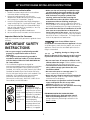
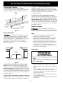
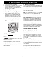
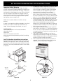
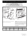
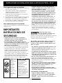
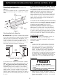
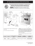
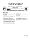
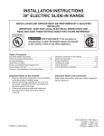
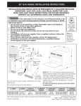
40" ELECTRIC RANGE INSTALLATION INSTRUCTIONS
INSTALLATION AND SERVICE MUST BE PERFORMED BY
A QUALIFIED INSTALLER.
IMPORTANT: SAVE FOR LOCAL ELECTRICAL INSPECTOR'S USE.
READ AND SAVE THESE INSTRUCTIONS FOR FUTURE REFERENCE.
40 1/8" Min.
(101.9 cm)
2 1/2" Min.
(6.4 cm Min.)
On left side
only, if there is a
wall
27 ¾"
(70.5 cm)
with
handle
B
30" Min.**
(76.2 cm Min.)
18" Min.
13" Min.
(45.7 cm Min.) (33 cm Min.)
36"
(91.4 cm)
feet
extended
47 ¼"
(120 cm)
Max.
24" Min.
(61 cm Min.)
24 1/2" max.
(62.2 cm Max.)
Grounded
Wall Outlet
Do not pinch the power supply cord between the range
and the wall.
43 ¾"
(111.1 cm)
With larger
door open
**NOTE: 24" (61 cm) minimum clearance between the
cooktop and the bottom of the cabinet when the bottom
of wood or metal cabinet is protected by not less than
1/4" (0.64 cm) flame retardant millboard covered with
not less than No. 28 MSG sheet metal, 0.015" (0.4 mm)
stainless steel, 0.024" (0.6 mm) aluminum, or 0.020"
(0.5 mm) copper.
Do not seal the range to the side cabinets.
30" (76.2 cm) minimum clearance when the cabinet is
unprotected.
A. HEIGHT
B. WIDTH
C. DEPTH TO FRONT
OF RANGE
D. DEPTH WITH
DOOR OPEN
E. MINIMUM
CUTOUT WIDTH
F. HEIGHT OF
COUNTERTOP
36" (91.4 cm)
40 1/8" (101.9 cm)
25 1/2" (64.8 cm)
43 3/4" (111.1 cm)
40 1/4" (102.2 cm)
36" (91.4 cm) standard
35 3/8" (90 cm) min.
1
P/N 318201701 (0201) Rev. D
English - pages 1 - 8
Español - páginas 9 - 16
40" ELECTRIC RANGE INSTALLATION INSTRUCTIONS
• Make sure the wall coverings around the range
can withstand the heat generated by the range.
• Before installing the range in an area covered
with linoleum or any other synthetic floor
covering, make sure the floor covering can
withstand heat at least 90°F/32°C above room
temperature without shrinking, warping or
discoloring. Do not install the range over carpeting
unless you place an insulating pad or sheet of 1/4" (6.4
mm) thick plywood between the range and carpeting.
• Do not obstruct the flow of combustion air at the
oven vent nor around the base or beneath the
lower front panel of the range. Avoid touching the
vent openings or nearby surfaces as they may become
hot while the oven is in operation. This range requires
fresh air for proper burner combustion.
Important Notes to the Installer
1. Read all instructions contained in these installation
instructions before installing range.
2. Remove all packing material from the oven
compartments before connecting the electrical supply
to the range (see "Preparation", page 6).
3. Install the 4 shipping bolts from range packaging as
range leveling legs (see "Leveling the Range", page 7)
4. Two anti-tip brackets MUST be removed from lower
back of range and MUST be installed (see "Anti-Tip
Bracket Installation", page 8).
5. Observe all governing codes and ordinances.
6. Be sure to leave these instructions with the consumer.
Important Note to the Consumer
Keep these instructions with your owner's guide for future
reference.
Never leave children alone or
unattended in the area where an appliance is in use.
As children grow, teach them the proper, safe use of all
appliances. Never leave the oven door open when the
range is unattended.
IMPORTANT SAFETY
INSTRUCTIONS
• Be sure your range is installed and grounded
properly by a qualified installer or service
technician.
• This range must be electrically grounded in
accordance with local codes or, in their absence,
with the National Electrical Code ANSI/NFPA No.
70—latest edition.
• The installation of appliances designed for
manufactured (mobile) home installation must conform
with Manufactured Home Construction and Safety
Standard, title 24CFR, part 3280 [Formerly the Federal
Standard for Mobile Home Construction and Safety,
title 24, HUD (part 280)] or when such standard is not
applicable, the Standard for Manufactured Home
Installation 1982 (Manufactured Home Sites,
Communities and Setups), ANSI Z225.1/NFPA 501Alatest edition, or with local codes.
• All ranges
can tip.
• Injury to
persons could
result.
• Install anti-tip
device
packed with
range.
Stepping, leaning or sitting on the
door(s) or drawer of this range can result in serious
injuries and can also cause damage to the range.
• Do not store items of interest to children in the
cabinets above the range. Children could be seriously
burned climbing on the range to reach items.
• To eliminate the need to reach over the surface
units, cabinet storage space above the units
should be avoided.
• Do not use the oven as a storage space. This
creates a potentially hazardous situation.
• Never use your range for warming or heating the
room. Prolonged use of the range without adequate
ventilation can be dangerous.
• Do not store or use gasoline or other flammable
vapors and liquids near this or any other
appliance. Explosions or fires could result.
• Reset all controls to the "off" position after using
a programmable timing operation.
To reduce the risk of
tipping of the range, the
range must be secured
by properly installed antitip bracket (s) provided
with the range. To
check if the bracket (s) is
installed properly,
remove the lower panel
or storage drawer and
verify that the anti-tip
bracket (s) is engaged.
FOR MODELS WITH SELF-CLEAN FEATURE:
• Remove broiler pan, food and other utensils
before self-cleaning the oven. Wipe up excess
spillage. Follow the precleaning instructions in the
Owner's Guide.
2
40" ELECTRIC RANGE INSTALLATION INSTRUCTIONS
Power Supply Cord Kit
Electrical Connection to the Range
The user is responsible for connecting the power supply
cord to the connection block located behind the back
panel access cover.
This appliance is manufactured with the neutral terminal
connected to the range.
While connecting range, do not
loosen the nuts which secure the terminal block to
the range. Electrical failure or loss of electrical
connection may occur.
This appliance may be connected by means of
permanent "hard wiring" (flexible armored or
nonmetallic shielded copper cable), or by means of a
power supply cord kit. Use only a power supply cord kit
rated at 125/250 volts minimum, 40 amperes minimum
and marked for use with ranges. See chart (below) for
cord kit connection opening size and rating information.
Cord must have either 3 or 4 conductors.
Electrical Shock Hazard
• Electrical ground is required on this appliance.
• Do not connect to the electrical supply until
appliance is permanently grounded.
• Disconnect power to the circuit breaker or fuse
box before making the electrical connection.
• This appliance must be connected to a
grounded, metallic, permanent wiring system,
or a grounding connector should be connected
to the grounding terminal or wire lead on the
appliance.
• Do not use the gas supply line for grounding
the appliance.
For mobile homes, new installations, recreational
vehicles, or areas where local codes do not permit
grounding through neutral, a 4 conductor power supply
cord kit rated at 125/250 volts minimum, 40 amperes
and marked for use with ranges should be used (see
Figure 4).
Terminals on end of wires must either be closed loop or
open-end spade lugs with upturned ends. Cord must
have strain relief clamp.
Risk of fire or electrical shock exists if
an incorrect size range cord kit is used, if the
Installation Instructions are not followed, or if the
strain relief bracket is discarded.
Failure to do any of the above could result in a
fire, personal injury or electrical shock.
Three Conductor Wire Connection to Range
(The 3-conductor cord or cable must be replaced with a
4-conductor cord or cable where grounding through the
neutral conductor is prohibited in new installations,
mobile homes, recreational vehicles or in other areas
where local codes do not permit neutral grounding)
If local codes permit connection of the frame grounding
conductor to the neutral wire of the copper power supply
cord (see Figure 3):
Range Connection Opening Size Chart
Refer to chart below for proper range connection opening size
and power supply cord kit ampere rating information. See serial
plate on range for kilowatt rating data.
Range Kilowatt Rating
Diameter (inches) of Range
(See Serial Plate on Range) Minimum Connection Opening
Cord kit
Direct
120/240 Volts 120/208 Volts Ampere
Rating
Cord Kit
Connection
0 -16.5 kW
0 -12.5 kW
40 Amp
16.6-22.5 kW 12.6-18.5 kW 50 Amp
1-3/8 in.
1-3/8 in.
1. Remove the 3 screws at the lower end of the rear
wire cover, then bend the lower end of the rear wire
cover (access cover) upward to expose range
terminal connection block (see Figure 2).
1-1/8 in.
1-3/8 in.
NOTE: Range is shipped from factory with
1 1/8" dia. hole as shown in figure 3. If a larger hole
is required, punch out the knockout.
3-Wire Wall
Receptacle
3-Wire Power
Supply Cord Kit
To gain access to lower terminal
block bend lower back cover plate
along row of holes shown here
Figure 1
Figure 2
3
40" ELECTRIC RANGE INSTALLATION INSTRUCTIONS
2. Remove the 3 loose nuts (after you removed the
rubber band) on the terminal block using 3/8" nut
driver or socket.
3. Connect the neutral white wire of the copper power
supply cord to the center silver-colored terminal of the
terminal block, and connect the other wires to the
outer terminals. Match wires and terminals by color
(red wires connected to the right terminal, black wires
connected to the left terminal).
4. Replace the 3 nuts on the terminal block (see
figure 3).
5. Lower the terminal cover and replace the 3 screws.
Four Conductor Wire Connection to Range
(mobile homes)
1. Remove the 3 screws at the lower end of the rear wire
cover, then raise the lower end of the rear wire cover
(access cover) upward to expose range terminal
connection block (see figure 2).
2. Remove the three loose nuts (after you removed the
rubber band) on the terminal block using a 3/8" nut
driver or socket.
3. Remove the grounding strap from the terminal block
and from the appliance frame.
4. Connect the ground wire (green) of the copper power
supply cord to the frame of the appliance with the
ground screw, using the hole in the frame where the
ground strap was removed (see Figure 4).
5. Connect the neutral of the copper power supply cord
to the center silver-colored terminal of the terminal
block, and connect the other wires to the outer
terminals. Match wires and terminals by color (red
wires connected to the right terminal, black wires
connected to the left terminal).
6. Replace the 3 nuts on the terminal block (see figure 4).
7. Lower the terminal cover and replace the 3 screws.
Silver colored Terminal
M Co
M Co P oun rd
ou r la ti
P nt d te ng
la in
te g
Red wire
Terminal
Block
White Wire
(Neutral)
Grounding
Strap
Black
wire
Terminal Block
Silver Colored
Terminal
A strainrelief
supplied by the user
must be installed at
this location
To 240 V
receptacle
1-1/8“ Dia.
Direct
Connection
Hole. Punch
out knockout
for 1-3/8“ Dia.
Cord Kit Hole
1-1/8“ Dia.
Direct
Connection
Hole. Punch
out knockout
for 1-3/8“ Dia.
Cord Kit Hole
Figure 3
A user
supplied
strain-relief
must be installed
at this location
M C
ou or
P nt d
la in
te g
Red
Wire
Black
Wire
Neutral
(White
Wire)
Ground
(Bare Copper
Wire)
To 240 V receptacle
NOTE: Be sure to remove the supplied
grounding strap
Figure 4
4
40" ELECTRIC RANGE INSTALLATION INSTRUCTIONS
Where local codes DO NOT permit connecting the
appliance grounding conductor to the neutral
(white) wire or if connecting to 4-wire electrical
system (see Figure 6).
1. Disconnect the power supply.
2. Separate the green (or bare copper) and white
appliance cable wires.
3. In the circuit breaker, fuse box or junction box:
a) Connect the white appliance cable wire to the
neutral (white) wire.
b) Connect the 2 black wires together.
c) Connect the 2 red wires together.
d) Connect the green (or bare copper) grounding
wire to the grounding wire of the circuit breaker,
fuse box or junction box.
Direct Electrical Connection to the Circuit
Breaker, Fuse Box or Junction Box
If the appliance is connected directly to the circuit breaker,
fuse box or junction box, use flexible, armored or non
metallic sheathed copper cable (with grounding wire).
Supply a U.L. listed strain-relief at each end of the cable.
At the appliance end, the cable goes through the Direct
Connection Hole (see figure 4) on the Cord Mounting
Plate. Wire sizes (copper wire only) and connections must
conform to the rating of the appliance.
Where local codes permit connecting the appliance
grounding conductor to the neutral (white) wire
(see Figure 5).(The 3-conductor cord or cable must be
replaced with a 4-conductor cord or cable where
grounding through the neutral conductor is prohibited in
new installations, mobile homes, recreational vehicles or
in other areas where local codes do not permit neutral
grounding)
1. Disconnect the power supply.
2. In the circuit breaker, fuse box or junction box:
a) Connect the green (or bare copper) wire, the white
appliance cable wire, and the neutral (white) wire
together.
b) Connect the 2 black wires together.
c) Connect the 2 red wires together.
Figure 6
4-Wire Electrical System
(example: Junction Box)
Figure 5
3-Wire (Grounded Neutral) Electrical System
(example: Junction Box)
5
40" ELECTRIC RANGE INSTALLATION INSTRUCTIONS
the cabinet. If back of range will not be flush with
the wall (the location of the outlet may not allow the
range to be positioned against the wall), draw a line on
the floor where the back edge of the range will be. Now
install anti-tip brackets (see "Anti-Tip Brackets
Installation", page 8).
Junction Box Location
Locate junction box as shown in Figure 7.
If a service cord is used, the wall receptacle should be
located in accordance with the dimensions below.
Center
Line of
Range
If range will not be installed against a cabinet,
move range into final position. Mark on the floor along
both sides of the range. If back of range will not be
flush with the wall (the location of the outlet may not
allow the range to be positioned against the wall), draw
a line on the floor where the back edge of the range will
be. Now install anti-tip brackets (see "Anti-Tip Brackets
Installation", page 8).
10"
(25.4 cm)
WALL
20"
(50.8 cm)
10"
(25.4 cm)
R
FLOO
7" Max.
(17.8 cm Max.)
Locate Electrical Hook-up
Inside Shaded Area
Center
Line of
Range
Range Installation
When unpacking the range, do not
discard the 4 shipping bolts. These are to be replaced on
the unit for use as leveling legs and height adjustments.
Figure 7
Range Placement
NOTE:
1. The back of the range may be installed directly
against the rear wall of the structure.
2. These ranges conform to U.L. requirements for "0"
spacing from the range to adjacent vertical walls
above the countertop level. However, to reduce
possible scorching of vertical walls and to minimize
potential fire hazards under abnormal surface unit
use conditions such as high heat or no pans, a
minimum of 2" (5.1 cm) spacing should be provided
on both sides of the cooktop.
To eliminate the risk of burns or fire by
reaching over heated surface units, cabinet storage
space located above the range should be avoided. If
cabinet storage space is to be provided, the risk can be
reduced by installing a range hood that projects
horizontally a minimum of 5" (12.7 cm) beyond the
bottom of the cabinet.
Preparation
Center
Line of
Range
Excessive Weight Hazard
• Use 2 or more people to move and install
range.
• Failure to follow this instruction can result in
back or other injury.
Follow instructions for
the type of installation you have
Figure 8
1. Put on safety glasses and gloves. Remove oven racks
and parts package from inside the oven. Remove
shipping materials, tape and protective film from the
range.
2. Take 4 cardboard corners from the carton. Stack one
on top of another. Repeat with other 2 corners.
Place corners lengthwise on the floor in back of the
range to support range.
3. Firmly grasp the range and gently lay it on its back
on the cardboard corners.
4. Remove and save the 4 shipping bolts from the skid.
Discard skid.
If range will be installed with a cabinet on both
sides, draw a center line on the floor between the
cabinets (see figure 8). If back of range will not be
flush with the wall (the location of the outlet may not
allow the range to be positioned against the wall), draw
a line on the floor where the back edge of the range will
be. Now install anti-tip brackets (see "Anti-Tip Bracket
Installation, page 8).
If range will be installed with a cabinet on one side
only, move the range into final position. Draw a line on
the floor along the side of the range that is not against
6
40" ELECTRIC RANGE INSTALLATION INSTRUCTIONS
2. Operation of Oven Elements
The oven is equipped with an electronic oven control. Each
of the functions has been factory checked before shipping.
However, it is suggested that you verify the operation of
the electronic oven controls once more. Refer to the
Owner's Guide for operation. Follow the instructions for the
Clock, Timer, Bake, Broil, Convection (some models) and
Clean (some models) functions.
5. Install 4 shipping bolts as leveling legs.
6. Lay a large piece of cardboard in front of the range.
Carefully stand the range upright on cardboard.
7. Adjust the leveling legs to a point where the range
base does not touch the floor.
Leveling the Range
Level the range and set cooktop height before
installation in the cut-out opening (if applicable).
1. Install an oven rack in the center of the oven.
2. Place a level on the rack (see figure 9). Take 2
readings with the level placed diagonally in one
direction and then the other. Level the range, if
necessary, by adjusting the 4 leg levelers with a
wrench (see Figure 11).
3. Slide range into cut-out opening and double check
for levelness. If the range is not level, pull unit out
and readjust leveling legs, or make sure floor is
level.
Bake–After setting the oven to 350°F (177°C) for baking,
the lower element in the oven should become red.
Broil–When the oven is set to BROIL, the upper element
in the oven should become red.
Clean (some models)–When the oven is set for a selfcleaning cycle, the upper element should become red
during the preheat portion of the cycle. After reaching
the self-cleaning temperature, the lower element will
become red.
Convection (some models)–When the oven is set to
CONV. BAKE/ROAST at 350°F (177°C), both elements
cycle on and off alternately and the convection fan will
turn. The convection fan will stop turning when the oven
door is opened during convection baking or roasting.
When All Hookups are Complete
Make sure all controls are left in the OFF position.
Model and Serial Number Location
The serial plate is located on the oven front frame
behind the large oven door.
Figure 9
Check Operation
Refer to the Owner's Guide packaged with the range for
operating instructions and for care and cleaning of your
range.
When ordering parts for or making inquiries about your
range, always be sure to include the model and serial
numbers and a lot number or letter from the serial plate
on your range.
Do not touch the elements. They may be
hot enough to cause burns.
Before You Call for Service
Read the Avoid Service Checklist and operating
instructions in your Owner's Guide. It may save you time
and expense. The list includes common occurrences that
are not the result of defective workmanship or materials
in this appliance.
Remove all packaging from the oven before testing.
1. Operation of Surface Elements
Turn on each of the four surface elements and check to
see that they heat. Check the surface element indicator
light(s), if equipped.
Refer to the warranty and service information in your
Owner's Guide for our phone number and address.
Please call or write if you have inquiries about your
range product and/or need to order parts.
7
40" ELECTRIC RANGE INSTALLATION INSTRUCTIONS
1. Unfold paper template and place it flat on the floor
with the back and side edges positioned exactly
where the back and sides of range will be located
when installed. (Use the diagram in figure 10 to
locate brackets if template is not available.)
2. Mark on the floor the location of the 4 mounting
holes (2 holes per bracket) shown on the template.
For easier installation, 3/16" (4.8 mm) diameter pilot
holes ½" (1.3 cm) deep can be drilled into the floor.
3. Remove template and place brackets on floor with
turned up flanges to the outside (see figure 10). Line
up holes in brackets with marks on floor and attach
with 4 screws provided (2 screws per bracket).
Brackets must be secured to solid floor. If attaching
to concrete floor, first drill 3/16" (4.8 mm) dia. pilot
holes using a masonry drill bit.
4. Level range if necessary, by adjusting 4 leg levelers
with wrench. (See Figure 11). A minimum clearance
of 1/8" (3.2 mm) is required between the bottom of
the range and the rear leg levelers to allow room for
the anti-tip brackets.
5. Slide range into place making sure rear legs are
trapped by ends of brackets. Range may need to be
shifted slightly to one side as it is being pushed back
to allow rear legs to align with brackets.
6. After installation, verify that the anti-tip bracket is
engaged. Open and remove drawer and check to
make sure the anti-tip bracket is engaged.
Important Safety Warning
To reduce the risk of tipping of the range, the range
must be secured to the floor by properly installed anti-tip
brackets and screws packed with the range. Those parts
are located in a plastic bag in the oven. Failure to install
the anti-tip brackets will allow the range to tip over if
excessive weight is placed on an open door or if a child
climbs upon it. Serious injury might result from spilled
hot liquids or from the range itself.
Follow the instructions below to install the anti-tip
brackets.
If range is ever moved to a different location, the anti-tip
brackets must also be moved and installed with the
range. To check for proper installation, see step 5.
Tools Required:
5/16" (8 mm) Nutdriver or Flat Head Screwdriver
Adjustable Wrench
Electric Drill
3/16" (4.8 mm) Diameter Drill Bit
3/16" (4.8 mm) Diameter Masonry Drill Bit (if installing
in concrete)
Anti-Tip Brackets Installation Instructions
Brackets attach to the floor at the back of the range to
hold both rear leg levelers. When fastening to the floor,
be sure that screws do not penetrate electrical wiring or
plumbing. The screws provided will work in either wood
or concrete.
Anti-Tip
Bracket
Slide
Back
¾"
(1.9 cm)
Anti-Tip
Bracket
1/2"
(1.3 cm)
Sides of
range
¾"
(1.9 cm)
Figure 10
Figure 11
8
INSTRUCCIONES DE INSTALACION PARA LA ESTUFA ELECTRICA DE 40"
LA INSTALACION Y EL SERVICIO DEBEN SER EFECTUADOS POR
UN INSTALADOR CALIFICADO.
IMPORTANTE: GUARDE ESTAS INSTRUCCIONES PARA USO DEL
INSPECTOR LOCAL DE ELECTRICIDAD.
LEA Y GUARDE ESTAS INSTRUCCIONES PARA REFERENCIA FUTURA.
40 1/8" Mín.
(101.9 cm)
2 1/2" Mín.
(6.4 cm Mín.)
Si hay uno pared,
el lado izquierdo
solamente
27 ¾"
(70.5 cm)
Con la manija
B
30" Mín.**
(76.2 cm Mín.)
18" Mín.
13" Mín.
(45.7 cm Mín.) (33 cm Mín.)
36"
(91.4 cm)
con las
patas
extendidas
47 ¼"
(120 cm)
máx.
24" Mín.
(61 cm Mín.)
24 1/2" Máx.
(62.2 cm Máx.)
Toma corriente de
pared puesto a tierra
No pellizque el cordón eléctrico entre la estufa y la pared.
43 ¾"
(111.1 cm)
Con la puerta
grande abierta
**NOTA: Un espacio mínimo de 24" (61 cm) entre la
superficie de la estufa y el fondo del armario cuando el
fondo del armario de madera o metal está protegido por
no menos de 1/4" (0.64 cm) de madera resistente al
fuego cubierta por una lámina metálica de MSG, número
28, 0.015" (0.4 mm) de acero inoxidable, 0.024" (0.6
mm) de aluminio, ô 0.02" (0.5 mm) de cobre.
No selle la estufa a los armarios de lado.
Un espacio mínimo de 30" (76.2 cm) cuando el armario
no está protegido.
A. ALTURA
B. ANCHURA
36" (91,4 cm)
40 1/8" (101.9 cm)
C. PROFUNDIDAD AL D. PROFUNDIDAD CON
FRENTE DE LA ESTUFA
PUERTA ABIERTA
25 1/2" (64,8 cm)
43 3/4" (111.1 cm)
9
E. MÍNIMO DE ANCHO
ESPACIO RECORTADO
F. ALTURA DE
MOSTRADOR
40 1/4" (102.2 cm)
36" (91.4 cm) normal
35 3/8" (90 cm) min.
P/N 318201701 (0201) Rev. D
English - pages 1 - 8
Español - páginas 9 - 16
INSTRUCCIONES DE INSTALACION PARA LA ESTUFA ELECTRICA DE 40"
• Asegúrese de que el material que recubre las
paredes alrededor de la estufa, pueda resistir el
calor generado por la estufa.
• Antes de instalar la estufa en un área cuyo piso
este recubierto con linóleo u otro tipo de piso
sintético, asegúrese de que éstos puedan resistir
una temperatura de por lo menos 90°F sobre la
temperatura ambiental sin provocar
encogimiento, deformación o decoloración. No
instale la estufa sobre una alfombra al menos que
coloque una plancha de material aislante de por lo
menos 1/4 pulgada, entre la estufa y la alfombra.
• No obstruya el flujo del aire de combustión en la
ventilación del horno ni tampoco alrededor de la
base o debajo del panel inferior delantero de la
estufa. Evite tocar las aberturas o áreas cercanas de
la ventilación, ya que pueden estar muy calientes
durante el funcionamiento del horno. La estufa
requiere aire fresco para la combustión apropiada de
los quemadores.
Notas importantes para el Instalador
1.
2.
3.
4.
5.
6.
Lea todas las instrucciones contenidas en este manual
antes de instalar la estufa.
Saque todo el material usado en el embalaje del
compartimiento del horno antes de conectar el
suministro eléctrico a la estufa.
Guarde los 4 pernos del empaque de la estufa para
usarlos como patas niveladoras.
Dos soportes antivuelco DEBEN quitarse de la parte de
inferior trasera de la estufa y DEBEN ser instalados.
Para detalles, vea instrucciones en la páginas 16.
Observe todos los códigos y reglamentos pertinentes.
Deje estas instrucciones con el comprador.
Nota Importante para el Consumidor
Conserve estas instrucciones y el Manual del Usuario para
referencia futura.
IMPORTANTES
INSTRUCCIONES DE
SEGURIDAD
Nunca deje niños solos o
desatendidos en un área donde un artefacto está
siendo usado. A medida que los niños crecen,
enséñeles el uso apropiado y de seguridad para todos los
artefactos. Nunca deje la puerta del horno abierta
cuando la estufa está desatendida.
• Asegúrese de que la estufa sea instalada y
conectada a tierra en forma apropiada por un
instalador calificado o por un técnico.
• Esta estufa debe ser eléctricamente puesta a
tierra de acuerdo con los códigos locales, o en su
ausencia, con el Código Eléctrico Nacional ANSI/
NFPA No. 70, última edición.
• La instalación de aparatos diseñados para instalación
en casas prefabricadas (móviles) debe conformar con
el Manufactured Home Construction and Safety
Standard, título 24CFR, parte 3280 [Anteriormente el
Federal Standard for Mobil Home Construction and
Safety, título 24, HUD (parte 280)] o cuando tal
estandard no se aplica, el Standard for Manufactured
Home Installation 1982 (Manufactured Home sites,
Communities and Setups), ANSI Z225.1/NFPA 501Aedición más reciente, o con los códigos locales.
• Todas las
estufas pueden
volcarse.
• Esto podría
resultar en
lesiones
personales.
• Instale el
dispositivo
antivuelcos que
se ha
empacado
junto con esta
estufa.
No se pare, apoye o siente en las
puertas o cajones de esta estufa pues puede
resultar en serias lesiones y puede también causar
daño a la estufa.
• No almacene artículos que puedan interesar a los
niños en los gabinetes sobre la estufa. Los niños
pueden quemarse seriamente tratando de trepar a la
estufa para alcanzar estos artículos.
• Los gabinetes de almacenamiento sobre la estufa
deben ser evitados, para eliminar la necesidad de
tener que pasar sobre los elementos superiores de
la estufa para llegar a ellos.
• No use el horno como espacio de almacenaje. Esto
creará una situación potencialmente peligrosa.
• Nunca use la estufa para calentar el cuarto. El uso
prolongado de la estufa sin la adecuada ventilación
puede resultar peligroso.
• No almacene ni utilice gasolina u otros vapores y
líquidos inflamables en la proximidad de éste o
de cualquier otro artefacto eléctrico. Puede
provocar incendio o explosión.
• Ajuste todos los controles a la posición "OFF"
(apagada) después de haber hecho una operación
con tiempo programado.
Para reducir el riesgo de
que se vuelque la estufa,
hay que asegurarla
adecuadamente
colocándole los soportes
antivuelco que se
proporcionan. Para
comprobar si estos están
instalados y apretados en
su lugar como se debe, ase
el borde trasero superior de
la estufa y cuidadosamente
inclínela hacia adelante
para asegurar que la estufa
se ancle.
PARA MODELOS AUTOLIMPIANTES:
• Saque la asadera, alimentos o cualquier otro
utensilio antes de usar el ciclo de autolimpieza
del horno. Limpié todo exceso de derrame de
alimentos. Siga las instrucciones de prelimpiado en el
Manual del Usuario.
10
INSTRUCCIONES DE INSTALACION PARA LA ESTUFA ELECTRICA DE 40"
Juego de Cordón Eléctrico
El consumidor tiene la responsabilidad de conectar el
cordón eléctrico al bloque de conexión ubicado detrás de
la cubierta de acceso del panel trasero.
Receptáculo de
Pared de 3
Alambres
Juego de Cordón
de Suministro
Eléctrico de 3
Alambres
Este artefacto puede ser conectado mediante "cableado
rígido" permanente (un cable fexible escudido o un
cable de cobre escudido no metálico) o un "juego de
cordón eléctrico". Se usará solamente un juego de
cordón eléctrico para 125/250 voltios mínimo, 40
amperios mínimo y marcado para uso con estufas. El
juego de cordón eléctrico debe tener 3 o 4 conductores.
Figura 1
Conexión Eléctrica de la Estufa
Este aparato se fabrica con el terminal neutro conectado
al marco.
Para las casas sobre ruedas, las nuevas instalaciones, en
los vehículos de recreación o en las áreas donde los
códigos locales no permiten la conexión del conductor a
tierra al neutro, un ensamblaje de suministro eléctrico de
4 conductores para estufas, clasificado a 125/250 voltios
mínimo, 40 amperios mínimo, debe de ser utilizado (vea
Figura 4).
Riesgo de Choque Eléctrico
• Una puesta a tierra está requerido en este
aparato.
• No lo conecte a la corriente eléctrica hasta que
el aparato haya sido puesto a tierra
permanentemente.
• Desconecte la corriente eléctrica a la caja de
empalmes antes de hacer la conexión eléctrica.
• Este aparato debe estar conectado con un
sistema de alambres puesto en tierra, metálico
y permanente o un conector de puesta a tierra
debe conectarse al terminal de puesta a tierra
o el alambre conductor en el aparato.
Los terminales en las puntas de los alambres deben ser
de circuito cerrado o de orejeta de pala punta abierta y
con las puntas vueltas hacia arriba. El cordón debe tener
un anclaje del cable.
Puede ocurrir riesgo de incendio o
choque eléctrico si se usa un juego de cordón de
estufa de tamaño incorrecto, si las instrucciones de
instalación no son seguidas o si no se usa el anclaje
del cable.
La falta de hacer cualquier de las cosas arriba
podría resultar en un incendio, choque eléctrico
o lesiones personales.
Tabla de tamaño de abertura de conexión de cocina
Referirse a la tabla de arriba para el tamaño de abertura de
connexión de cocina adecuada, y la información sobre el regimén
de amperios del ensamblaje de cordón de suministro eléctrico.
Vea la placa de serie de la
cocina para información
sobre el regimén de
kilovatio.
120/240 Volts 120/208 Volts
0-16.5 Kw
0-12.5 Kw
16.6-22.5 Kw 12.6-18.5 Kw
Conexión de tres alambres de conducción a
la estufa
Diametro (pulgadas) de
Mínimo
regimén de abierta de conexión de
amperios cocina.
de
ensamblaje Dimensión
Conexión
del cordón
agujero
directo
Connexión
40 Amp
50 Amp
1 3/8 pulg
1 3/8 pulg
(Un cordón flexible o cable de 3 conductores debe de ser
reemplazado con un cordón flexible o cable de 4 conductores donde la conexión del conductor a tierra al neutro esta
prohibida en las nuevas instalaciones, las casas sobre
ruedas, los vehículos de recreación o otras áreas donde los
códigos locales no
permiten la
conexión a tierra al
neutro.)
Si los códigos
locales permiten
la conexión del
conductor de
tierra del marco
con el alambre
neutro del cordón
eléctrico de cobre
Para obtener acceso al
(vea Figura 3):
1 1/8 pulg
1 3/8 pulg
NOTA: La estufa viene de fábrica preparada para funcionar
con un hueco de 1 1/8" de diametro come se muestra en la
figura 3. En caso de necesitarse un hueco más grande retire
la cubierta.
Al realizar la conexión de la estufa, no
desaprete las tuercas que aseguran el alambraje de la
estufa al bloque terminal instalado en la fábrica. Se puede
ocurrir corte de energía o pérdida de conexión eléctrica.
Figura 2
11
tablero inferior de bornes,
doble hacia atrás la placa de
la cubierta trasera por la fila
de agujeros que se ven aquí.
INSTRUCCIONES DE INSTALACION PARA LA ESTUFA ELECTRICA DE 40"
Conexión de 4 alambres de conducción a la
estufa (casas móviles)
1. Quite los tres tornillos en la parte más baja del panel
trasero, luego levante la parte más baja del panel
trasero (la cubierta de acceso) exponiendo el bloque
de conexiones de los terminales de la estufa (vea
Figura 2).
2. Quinte las tres tuercas desatadas (después de
remover la cinta de goma) sobre el bloque terminal
usando un destornillador o una llave de casquillo de
3/8".
3. Conecte el cable neutro del cordón eléctrico de cobre
al terminal de color de plata en el centro del bloque,
y conecte los otros cabels a los terminales laterales.
Empareje los cables y los terminales según el color
(cables rojos conectados con el terminal derecho,
cables negros conectados con el terminal izquierdo).
4. Baje la cubierta del terminal y reinstale los tres (3)
tornillos.
5. Baje la cubierta del terminal y reponga los 3 tornillos.
1. Quite los tres tornillos en la parte más baja del panel
trasero, luego levante la parte más baja del panel
trasero (la cubierta de acceso) exponiendo el bloque
de conexiones de los terminales de la estufa (vea
figura 2).
2. Retire las 3 tuercas (después de haber removido la
banda de goma) sobre el bloque terminal usando un
manguito o destornillador de casquillo de 3/8"
pulgadas.
3. Quite la banda de puesta a tierra del bloque de los
terminales y del marco del artefacto. Retenga el
tornillo de puesta a tierra.
4. Conecte el alambre de puesta a tierra (verde) del
cordón eléctrico de cobre al marco del artefacto con
el tornillo de puesta a tierra, usando el agujero en el
marco donde se quitó el tornillo de puesta a tierra
(vea figura 4).
5. Conecte el alambre neutro (blanco) del cordón
eléctrico de cobre al terminal de color de plata en el
centro del bloque y conecte los otros alambres al los
terminales laterales. Conecte los alambres y
terminales emparejando los colores (los alambres rojos
conectsdos al terminal derecho, los alambres negros
conectados al terminal izquierdo).
6.Reponga las 3 tuercas sobre el bloque terminal (vea
figura 4).
7. Baje la cubierta de acceso y vuelva a poner los 3
tornillos.
Terminal
plata
d Co
de e la rd
ó
m pl n
on ac
ta a
je
Alambre
Rojo
Alambre
Negro
Una arazadera
de releva
provista debe de
estar instalada a
está ubicación
Neutro
(Alambre
Blanco)
Banda
de puesta
a tierra
Hacia el 240 V
receptáculo
Bloque terminal
Terminal
plata
Alambre
Rojo
1-1/8“ Dia.
Agujero de la
conexión directa.
Retira la arandela
pre-cortada para
1-3/8“ Dia. Agujero
1-1/8“ Dia.
Agujero de la
Alambre
conexión
Negro
directa.Retira
la arandela
pre-cortada
para 1-3/8“ Dia.
Agujero
Figura 3
d Co
de e la rd
ó
m pl n
on ac
ta a
je
Bloque terminal
Neutro
(Alambre
Blanco)
Puesta a tierra
(cable de
cobre)
Una arazadera
de releva provista
debe de estar
instalada a está
ubicación
Hacia el 240 V
receptáculo
NOTA: Asegurese de quitar la banda de puesta a tierra
provista.
Figura 4
12
INSTRUCCIONES DE INSTALACION PARA LA ESTUFA ELECTRICA DE 40"
Donde los códigos locales NO permitan conectar el
conductor de puesta a tierra del eléctrodoméstico al
neutral (blanco), o si está conectado con un sistema a
4 alambres (vea figura 6):
1. Desconecte el suministro eléctrico
2. Separe el alambre verde (o cobre desnudo) y el
alambre blanco del electrodoméstico.
3. En el cortacircuito, la caja de fusibles o la caja de
empalmes.
a. Conecte el alambre blanco del cable del
eléctrodoméstico al alambre neutral (blanco).
b. Conecte los 2 alambres negros juntos.
c. Conecte los 2 alambres rojos juntos.
d. Conecte el alambre verde (o de cobre desnudo) de
la puesta a tierra del alambre al alambre de
puesta a tierra del cortacircuito, de la caja de
fusibles o de la caja de empalmes.
Conexión eléctrica directa al cortacircuito, a
la caja de fusibles o la caja de empalmes
Si el aparato está conectado directamente al cortacircuito,
a la caja de fusibles o a la caja de empalmes, use un cable
blindado flexible o no metálico recubierto de cobre (con
alambre a tierra). Provee una abrazadera releva de anclaje
homologo UL a cada extremidad del cable. A la
extremidad del eléctrodoméstico, el cable pase a través del
agujero de la conexión directa (vea figura 4) en el cable de
la placa de montaje. El tamaño de los alambres (alambre
de cobre solamente) y las conexiones deben estar
conforme al regimén del eléctrodoméstico.
Donde los códigos locales permitan conectar el
conductor de puesta a tierra del eléctrodoméstico al
neutral (blanco) (vea figura 5):
(Un cordón flexible o cable de 3 conductores debe de ser
reemplazado con un cordón flexible o cable de 4 conductores donde la conexión del conductor a tierra al neutro esta
prohibida en las nuevas instalaciones, las casas sobre
ruedas, los vehículos de recreación o otras áreas donde los
códigos locales no permiten la conexión a tierra al neutro.)
1. Desconecte el suministro eléctrico.
2. En el cortacircuito, la caja de fusibles o la caja de
empalmes
a) Conecte el alambre verde (o cobre desnudo), el
alambre blanco del cable del eléctrodoméstico y el
alambre neutral (blanco) juntos.
b) Conecte los dos alambres negros juntos.
c) Conecte los dos alambres rojos juntos.
Figura 6 - Sistema eléctrico de 4 alambres
(ejemplo caja de empalme)
Figura 5 - Sistema eléctrico (ejemplo: caja de
empalmes) de 3 alambres (a tierra neutral)
13
INSTRUCCIONES DE INSTALACION PARA LA ESTUFA ELECTRICA DE 40"
Si la estufa se va a instalar con un armario a sólo un
lado, mueva la estufa a su posición final. Marque el piso
por el lado de la estufa que no estará contra el armario.
Si la parte trasera de la estufa no estará a ras con la
pared (la ubicación del tomacorriente puede que no
permita que la estufa se pegue a ras con la pared),
marque el piso donde el borde trasero de la estufa estará.
Ponga el patrón en el piso y alinie el lado del patrón con
la línea marcada en el piso. Alinie la parte trasera del
patrón con la pared trasera o la línea marcada para la
parte de atrás de la estufa.
Situación de caja de unión
Localice la caja de empalmes como se ve en la
Figura 7.
Si se usa un cordón de servicio, el receptáculo de pared
debe estar localizado según las medidas que se indican
abajo.
Center
Line of
Range
DE LA ESTUFA
10"
(25.4 cm)
ALL
W
PARED
20"
(50.8 cm)
Si la estufa no será instalada junta contra un armario,
mueva la estufa a su posición final. Marque el piso por los
dos lados de la estufa. Si la parte trasera de la estufa
no estará a ras con la pared (la ubicación del
tomacorriente puede que no permita que la estufa se
pegue a ras con la pared), marque en el piso donde el
borde trasero de la estufa estará. Ponga el patrón en el
piso y alinie los lados del patrón con las líneas marcadas
en el piso. Alinie la parte trasera del patrón con la pared
trasera o la línea marcada para la parte trasera de la
estufa (vea instalación del Soportes Antivuelco página 8).
10"
(25.4 cm)
R
PISO
LOO
F
7" Max.
(17.8 cm Max.)
UBIQUE LO ELECTRICO
Locate Electrical
DENTRO
DEL AREAHook-up
Inside Shaded Area
SOMBREADA
Center
Line of
Range
DE LA
ESTUFA
Figura 7
Construcción de los Armarios
Instalación de la estufa
Para eliminar el riesgo de quemaduras
e incendios al tocar superficies sobrecalentadas, se debe
evitar colocar espacio para armarios de almacenamiento
sobre las estufas con elementos al descubierto. Si se
instalan armarios sobre la estufa, se pueden reducir tales
riesgos instlando una campana purificadora que se
proyecta horizontalemente un mínimo de 5" (12.7 cm)
más afuera de la parte inferior de los armarios.
Mientras se desembala la estufa, ne
deseche los cuatro (4) pernos de embabalaje.
Reemplácelos como patas niveladoras y para ajustar la
altura de la unidad.
NOTA:
1. La parte trasera de la estufa puede ser directamente
instalada a ras con la pared trasera de la estructura.
2. Estas estufas se conforman a los requerimientos U.L.
para espaciamiento “0” desde la estufa hasta las
paredes verticales adyacentes arriba del nivel del
tablero. No obstante, para reducir la posibilidad de
quemar las paredes verticales y para disminuir el
posible peligro de incendio bajo condiciones anormales
de uso de la tapa con hornillas como alto calor o la
ausencia de cazuelas, se debe dejar un espacio de un
mínimo de 2" (5.1 cm) en ambos lados de la tapa.
Center
Line of
Range
Follow instructions for
Siga las instrucciones para el tipo de
the type of installation you have
instalación que usted tenga
Preparación
Figura 8
Si la estufa se va a instalar con un armario a ambos
lados, marque el centro de la abertura del armario en el
piso. Si la parte trasera de la estufa no estará a ras
con la pared (la ubicación del tomacorriente puede que
no permita que la estufa se pegue a ras con la pared),
marque el piso donde estará el border trasero de la estufa.
Ponga el patrón en el piso, alineando la línea del centro
del patrón con la marca en el centro de la abertura del
armario. Ponga el borde trasero del patrón a ras contra la
pared trasera o la línea marcada para la parte de atrás de
la estufa.
Peligro de Peso Excesivo
• Use 2 personas o más para mover e instalar la
estufa.
• Si no cumple con esta instrucción, puede resultar
en daño a la espalda u otra lesión.
1. Póngase guantes y anteojos de seguridad. Quite las
parrillas del horno y paquete de piezas de adentro del
horno. Quite materiales de empaque, cinta y película
protectiva de la estufa.
14
INSTRUCCIONES DE INSTALACION PARA LA ESTUFA ELECTRICA DE 40"
2. Tome las 4 esquinas de cartón de la caja de empaque.
Colóquelas una encima de otra. Repita esta operación
con las otras 2 esquinas. Coloque las esquinas
longitudinalmente en el piso detrás de la estufa, para
apoyarla.
3. Sujete firmemente la estufa y suavamente recuéstela
en su respaldo, en las esquinas de cartón.
4. Quite y guarde los 4 pernos de empaque de la
corredera. Descarte la corredera.
5. Instale los 4 pernos de transporte como patas de
nivelación.
6. Ponge el cartón delante de la estufa. Cuidadosamente
pare la estufa en el cartón.
7. Ajuste la patas de nivelación al punto en que la base
de la estufa no toque el piso.
2. Funcionamiento de los Elementos del Horno
El horno está equipado con un control electrónico. Cada
función ha sido probada en la fábrica antes del transporte.
Sin embargo, sugerimos que Ud. verifique el
funcionamiento de los controles del horno una vez más.
Véase el Manual del Usuario para la operación. Siga las
instrucciones par el Reloj, Minutero, Cocer, Asar,
Covección (algunos modelos) y las funciones de limpieza
(algunos modelos).
Nivelación de la estufa
Limpieza/Clean (algunos modelos)–Cuando el horno
está puesto para un ciclo de auto-limpieza, el element
superior se pondrá rojo durante el período de
precalentamiento del ciclo. Después de alcanzar la
temperatura de auto-limpieza , el elemento inferior se
pondrá rojo.
Cocer/Bake–Después de poner el horno a 350°F (177°C)
para cocer, el element inferior debe ponerse rojo
Asar/Broil–Cuando está puesto para BROIL, el elemento
superior se debe poner rojo.
Nivele la estufa y ajuste la altura de la estufa antes
de instalarla en la abertura.
1. Coloque una parrilla del horno en el centro del horno.
2. Ponga un nivel sobre la parrilla (vea figura 9). Tome
dos lecturas con el nivel puesto diagonalmente en una
dirección y después en la otra. Nivele la estufa, si es
necesario, ajustando las 4 patas niveladoras con una
llave de tuercas (Figura 10).
3. Deslice la estufa en la abertura y verifique la nivelación
otra vez. Si la estufa no es nivelada, tire la unidad
hacia afuera y reajuste las patas niveladoras, o verifique
que el piso sea nivelado.
Convección/Convection (algunos modelos)–Cuando
el horno se pone a CONV. BAKE/ROAST a 350°F
(177°C), los dos elementos se enciendan y se apagan
alternando en un ciclo y el ventilador se pone en
marcha. El ventilador de convección se parará cuando
se abre la puerta del horno durante el cocido o el asado
por convección.
Después de Terminar la Instalación
Asegúrese de que todos los controles estén en la posición
OFF (apagada).
Ubicación del Número de Modelo y de Serie
La placa con el número de serie está ubicada en el
marco delantero del horno detrás de la puerta del horno
grande.
Cuando haga pedidos de repuestos o solicite información
con respecto a su estufa, esté siempre seguro de incluir
el número de modelo y de serie y el número o letra del
lote de la placa de serie de su estufa.
Figura 9
Comprobación del Funcionamiento
Consulte el Manual del Usuario incluído con la estufa
para instrucciones de operación y instrucciones para el
cuidado y limpieza de su estufa.
Antes de Llamar al Servicio
Lea la sección Lista de control de averías en su Manual
del Usuario. Esto le podrá ahorrar tiempo y gastos. Esta
lista incluye ocurrencias comunes que no son el
resultado de defectos de materiales o fabricación de
este artefacto.
No toque los elemento. Pueden estar
bastante calientes para causar quemaduras.
Quite todo el embalaje de la unidad antes de
comprobarla.
Lea la garantía y la información sobre el servicio en su
Manual del Usuario para obtener el número de teléfono
gratuito y la dirección del servicio. Por favor llame o
escriba si tiene preguntas acerca de su estufa o necesita
repuestos.
1. Operación de los elementos de superficie
Encienda cada uno de los cuatro elementos de superficie y
controle que se calienten. Verifique el funcionamiento de
las luces indicadoras de los elementos de superficie, si
equipadas.
15
INSTRUCCIONES DE INSTALACION PARA LA ESTUFA ELECTRICA DE 40"
1.
Importante Advertencia de Seguridad
Para reducir el riesgo de que la estufa se vuelque, es
necesario asegurarla al piso instalando los soportes
antivuelco y los tornillos suministrados con la estufa. Las
piezas se encuentran en un saco de plástico en el horno.
Si no se instalan los soportes antivuelco, la estufa se
puede volcar si se coloca exceso de peso en una puerta
abierta o si un niño se sube a ella. Se pueden ocasionar
lesiones graves causadas por los líquidos calientes
derramados o por la estufa misma.
2.
3.
Siga las instrucciones que más abajo se indican para
instalar los soportes antivuelco.
Si la estufa es movida a otro lugar, los soportes
antivuelco deben también ser movidos e instalados en la
estufa. Para controlar la instalación apropiada, vea el
paso número 5.
Herramientas Necesarias:
Llave de tuerca de 5/16" (8 mm) o destornillador para
tornillos de cabeza plana
Llave inglesa
Taladro eléctrico
Broca de 3/16" (4.8 mm) de diámetro
Broca para taladro de mampostería de 3/16" (4.8 mm)
de diá. (si se está instalando en concreto)
4.
5.
Instrucciones de Instalación del Soporte
Antivuelco
Los soportes se fijan al suelo en la parte trasera de la
estufa para sujetar ambos niveladores de las patas
traseras. Cuando los esté instalando al piso, asegúrese
de que los tornillos no penetren el alambrado eléctrico o
plomería. Los tornillos provistos pueden utilizarse en
madera o concreto.
Deslice
Hacia atras
Pata
niveladora
Soporte
Antivuelco
Soporte
Antivuelco
P
AR
ED
TR
AS
¾"
(1.9 cm)
A
ER
1/2"
(1.3 cm)
Desdoble la plantilla de papel y colóquela plana en
el piso con los bordes laterales y el trasero colocados
exactamente donde la parte trasera y los lados de la
estufa serán colocados cuando sea instalada. (Use el
diagrama siguiente para ubicar los soportes si no se
dispone de la plantilla).
Marque en el piso la ubicación de los 4 agujeros de
montaje como se muestra en la plantilla. Para
facilitar la instalación, se pueden taladrar agujeros
piloto de 3/16" (4.8 mm) de diám. y 1/2" (1.3 cm)
de profundidad en el piso.
Saque la plantilla y coloque los soportes en el piso
con la brida hacia arriba dirigida hacia el frente.
Alinee los agujeros en los soportes con las marcas en
el piso y sujete con los 4 tornillos provistos. Los
soportes deben estar asegurados al piso firme. Si se
va a instalar en piso de concreto, primero debe
taladrar agujeros guía de 3/16" (4.8 mm) de
diámetro usando una broca para taladro de
mampostería.
Nivele la estufa si es necesario ajustando las cuatro
patas niveladoras con una llave (Ver la Figura 11
abajo). Se requiere un espacio libre mínimo de 1/8"
(3.2 mm) entre la parte inferior de la estufa y los
niveladores de las patas traseras para dejar espacio
para los soportes antivuelco.
Deslice la estufa a su lugar asegurándose de que las
patas traseras estén sujetas por los extremos de los
soportes. La estufa puede necesitar ser movida
ligeramente a un lado cuando está siendo empujada
hacia atrás para permitir que las patas se alineen con
los soportes. Usted también puede asir el borde
trasero de la cima de la estufa y cuidadosamente
intentar voltearla para asegurarse de que la estufa
sea adecuadamente anclada.
A
DE L
DO
FON STUFA
E
Lados de la
estufa
Levantar
Bajar
¾"
(1.9 cm)
Figura 10
Figura 11
16