1
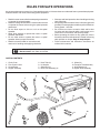
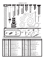
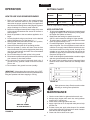
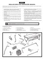
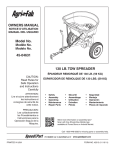
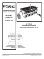
OWNERS MANUAL
MANUAL DEL USUARIO
Model No.
Modelo No.
45-0309-062
32" POLY
SPIKER/SPREADER
SURCADOR-ESPARCIDOR DE 32”
CAUTION:
Read Rules for
Safe Operation
and Instructions
Carefully
•
•
•
•
•
Safety
Assembly
Operation
Maintenance
Parts
PRECAUCION:
Lea cuidadosamente los
Porcedimientos e
Instrucciones para la
Operación Segura de la
Máquina.
•
•
•
•
•
Seguridad
Montaje
Operación
Mantenimiento
Piezas de Repuesto
Call 1-800-448-9282 for missing parts or assembly help.
PRINTED IN U.S.A.
FORM NO. 42172 rev. (6/22/11)
RULES FOR SAFE OPERATIONS
Any power equipment can cause injury if operated improperly or if the user does not understand how to operate the equipment.
Exercise caution at all times, when using power equipment.
• Wear eye and hand protection when handling and using
lawn chemicals.
• Always begin with the transmission in first (low) gear and
gradually increase speed as conditions permit. Maximum
towing speed - 10 M.P.H.
• Do not drive too close to a creek or ditch and be alert
for holes and other hazards which could cause you to
loose control of the tractor and spiker/spreader.
• Before operating the vehicle on any grade (hill) refer to
the safety rules in the vehicle owner's manual concerning
safe operation on slopes. Stay off steep slopes!
• Follow maintenance and lubrication instructions as
outlined in this manual.
• Read this owner's manual before attempting to assemble
or operate the spiker/spreader.
• Read the towing vehicle owner's manual and know how
to operate the tractor before using the spiker/spreader
attachment.
• Do not allow anyone to ride on or sit on the spiker/
spreader.
• Never allow children to operate the tractor or spiker/
spreader attachment.
• Do not allow adults to operate the tractor or spiker/
spreader without proper instructions.
• Read the chemical label for instructions and
cautions for handling and applying chemicals.
Look for this symbol to point out important safety precautions. It means – Attention!!
Become alert!! Your safety is involved.
CARTON CONTENTS
1.
2.
3.
4.
5.
6.
7.
8.
Chain Cover
Flow Control Lever
Center Brace
Hopper Assembly
Hitch Tube (2)
Lift Handle
Spike Disk (7)
Drive Disk Assembly (2)
2
9. Wheel (2)
10.Transport Tube Assembly
11. Hitch Bracket (2)
12. Spiker Shaft Assembly
4
3
1
5
10
6
7
9
11
8
2
12
SHOWN FULL SIZE
A
C
B
D
E
H
G
F
I
Q
P
V
U
R
K
T
L
J
M
S
W
N
O
NOT SHOWN FULL SIZE
X
Z
Y
HH
EE
CC
II
AA
FF
GG
DD
BB
JJ
HARDWARE CHART
REF. PART NO. QTY
A
B
C
D
E
F
G
H
I
J
K
L
M
N
O
P
Q
R
45100
43224
44180
43084
43085
43063
1509-90
43012
44215
44731
43178
47189
47810
43019
48115
43088
1543-69
43081
2
3
2
2
2
1
1
1
1
2
1
5
10
2
2
2
2
4
DESCRIPTION
Hex Bolt, 1/2" x 4" Full Thread
Hex Bolt, 5/16" x 2-1/4"
Hex Bolt, 5/16" x 2"
Hex Bolt, 5/16" x 1-3/4"
Hex Bolt, 5/16" x 1-1/2"
Hex Bolt, 5/16" x 1"
Hex Bolt, 1/4-20 x 1-1/4"
Hex Bolt, 1/4-20 x 3/4"
Carriage Bolt, 5/16" x 1-3/4"
Self Tapping Screw, 1/4" x 1/2"
Hex Nut, 1/4"
Nylock Hex Nut, 1/4"
Nylock Hex Nut, 5/16"
Jam Nut, 1/2"
Nylock Jam Nut, 1/2"
Flat Washer, 1/4"
Nylon Washer, 21/64"
Flat Washer, 5/16"
REF. PART NO. QTY
S
T
U
V
W
X
Y
Z
AA
BB
CC
DD
EE
FF
GG
HH
II
JJ
3
R19171616
R19212016
43093
44101
43343
47960
741-0249
47777
23520
46497
46524
47959
47969
43848
43943
712-0421
47623
47962
4
10
3
1
1
1
13
1
1
2
5
1
1
1
1
1
1
1
DESCRIPTION
Flat Washer, 1/2"
Flat Washer, 5/8"
Cotter Pin, 1/8" x 1-1/2"
Cotter Pin, 3/32" x 3/4"
Hair Cotter Pin, 1/8"
Chain with Connecting Link
Flanged Bearing
Compression Spring
1/4" Thick Spacer
Short Spacer Tube
Long Spacer Tube
Flow Control Link
Ferrule
Control Lever Grip
Height Adjustment Grip
Plastic Wing Nut
Flat Head Hitch, Pin, 3/8"
Flow Plate Spring
ENGLISH
ASSEMBLY
4. Assemble the grip onto the lift handle. See figure 2.
5. On the right side, insert a 5/16" x 1-3/4" hex bolt through
a 5/16" flat washer and then through the rear hole in the
hopper and the hitch tube. Assemble the transport tube
and then the lift handle onto the bolt and secure with a
5/16" nylock hex nut. Do not tighten yet. See figure 2.
6. Assemble a 5/16" x 1" hex bolt and 5/16" nylock hex nut
to the bottom hole in the transport tube assembly and
the lift handle. Tighten. See figure 2.
TOOLS REQUIRED FOR ASSEMBLY
(2) 7/16" Wrenches
(2) 1/2" Wrenches
(2)3/4" or Adjustable Wrenches
(1) Screwdriver
(1) Pliers
(GG) GRIP
LIFT
HANDLE
(R) 5/16"
FLAT WASHER
(D) 5/16" x 1-3/4"
HEX BOLT
Spike points are sharp. Exercise caution when
handling and working near spike disks.
(F) 5/16" x 1"
HEX BOLT
1. Remove the hardware pack and all individual parts from
the carton. Lay out as shown on pages 2 and 3.
2. Attach a hitch tube to the front hole in the right hand side
of the hopper using a 5/16" x 1-1/2" hex bolt, a 5/16" flat
washer and a 5/16" nylock hex nut. Assemble the bolt
and washer from inside the hopper. Do not tighten yet.
See figure 1.
(M) 5/16" NYLOCK
HEX NUT
3. Repeat on the left hand side of the hopper.
TRANSPORT TUBE
FIGURE 2
VIEWED FROM FRONT RIGHT CORNER
7. On the left side, insert a 5/16" x 1-3/4" hex bolt through
a 5/16" flat washer and then through the rear hole in the
hopper and the hitch tube. Assemble the transport tube
onto the bolt and secure it with a 5/16" nylock hex nut.
Do not tighten yet. See figure 3.
(E) 5/16" 1-1/2"
(R) 5/16" FLAT
HEX BOLT
WASHER
VIEWED FROM FRONT LEFT CORNER
(D) 5/16" x 1-3/4"
HEX BOLT
HITCH TUBE
(M) 5/16" NYLOCK HEX NUT
FIGURE 1
FIGURE 3
4
(R) 5/16" FLAT
WASHER
(M) 5/16" NYLOCK
HEX NUT
ENGLISH
8. Fasten the hitch tubes together using three 5/16" x 2-1/4" hex bolts and 5/16" nylock hex nuts. Do not
tighten yet. See figure 4.
14.If the wheel does not spin freely, back off the nylock jam
nut and then the plain jam nut 1/4 to 1/2 turn each.
15.Assemble a wheel to the other side. See figure 6.
TRANSPORT
TUBE
(M) 5/16" NYLOCK
HEX NUT (3)
(S) 1/2" FLAT
WASHER
(B) 5/16" x 2-1/4"
HEX BOLT (3)
(O) 1/2" NYLOCK
JAM NUT
FIGURE 4
(A) 1/2" x 4"
HEX BOLT
(N) 1/2" HEX
JAM NUT
FIGURE 6
9. Assemble the hitch brackets to the hitch tubes using two
5/16" x 2" hex bolts and 5/16" nylock hex nuts. Do not
tighten. See figure 5.
10.Assemble the hitch pin through the hitch brackets and
secure with the hair cotter pin. See figure 5.
IMPORTANT: Do not collapse the flat ends of the hitch
tubes when tightening the bolts in the next step.
11.Tighten, but do not overtighten the two 5/16" x 1-1/2"
hex bolts assembled in steps 2 and 3.
Tighten, but do not overtighten the two 5/16" x 1-3/4"
hex bolts assembled in steps 5 and 7. The lift handle
must be able to pivot.
Tighten the hex bolts assembled in steps 8 and 9.
16.Screw a 1/4" hex nut all the way onto the flow control
link. Assemble the ferrule onto the link and then start a
1/4" nylock hex nut one or two turns onto the link. See
figure 7.
17.Assemble the ferrule into the hole at the end of the flow
control lever using a 1/4" nylock hex nut. Tighten the
nut, leaving it loose enough that the ferrule can pivot.
See figure 7.
18.Assemble the grip onto the end of the flow control lever.
See figure 7.
(FF) GRIP
(C) 5/16" x 2"
HEX BOLT (2)
(II) HITCH PIN
FLOW
CONTROL
LEVER
(W) HAIR COTTER
PIN (1/8")
(L) 1/4" NYLOCK
HEX NUT
(M) 5/16" NYLOCK
HEX NUT (2)
FIGURE 5
(EE) FERRULE
12.Assemble a 1/2" flat washer, a wheel, another 1/2" flat
washer and then a 1/2" jam nut onto a 1/2" x 4" hex bolt.
Tighten the nut finger tight and then back off 1/4 to 1/2
turn. See figure 6.
13.Assemble the bolt and wheel to the transport tube using
a 1/2" nylock jam nut. Tighten the nut but don't collapse
the tube. See figure 6.
(DD) FLOW
CONTROL
LINK
FIGURE 7
5
(L) 1/4" NYLOCK
HEX NUT
(K) 1/4" HEX NUT
ENGLISH
24.Move the flow control lever as far as it will go to the "OFF"
position. Push the feed plate back as far as it will go to
the closed position. See figure 10.
25.Place a nylon washer onto the bent end of the flow control
link and then insert the link into the feed plate bracket.
Secure it with a 3/32" x 3/4" cotter pin. See figure 10.
26.Tighten the lower 1/4" hex nut until it touches the bottom
of the ferrule, then tighten the upper 1/4" nylock hex nut
until it is snug against the top of the ferrule. See figure
10.
27.Hook the open end of the spring into the feed plate.
Place the closed end of the spring onto the end of the
hex bolt in the flow control lever. Secure it with a 1/4"
nylock hex nut. See figure 10.
28.Open and close the feed plate using the flow control lever.
Check to make sure the feed plate is closed completely
when the lever is in the "OFF" position. If the feed plate
does not close completely, adjust the 1/4" nylock hex
nuts on the flow control link. See figure 10.
19. Place the flow control lever into the slot in the hopper.
See figure 8.
20.Place the center brace into the hopper. Insert the 1/4" x
1-1/4" hex bolt through the center brace and the front of
the hopper. Assemble a 1/4" flat washer, the flow control
lever and a 1/4" nylock hex nut onto the bolt. Do not
tighten yet. See figure 8.
21.Insert the 1/4" x 3/4" hex bolt through the center brace
and the rear of the hopper. Assemble a 1/4" flat washer
and 1/4" nylock hex nut onto the bolt. Tighten both the
front and rear bolts. See figure 8.
CENTER
BRACE
(G) 1/4" x 1-1/4"
HEX BOLT
(P) 1/4" FLAT (H) 1/4" x 3/4"
WASHER
HEX BOLT
(L) 1/4" NYLOCK
HEX NUT
FLOW
CONTROL
LEVER
(L) 1/4" NYLOCK
HEX NUT
(P) 1/4" FLAT
WASHER (L) 1/4" NYLOCK
HEX NUT
(JJ) EXTENSION
SPRING
FIGURE 8
(L) 1/4" NYLOCK
HEX NUT
22.Insert the 5/16" x 1-3/4" carriage bolt up through the slot
and secure it with a nylon washer and the plastic wing
nut. See figure 9.
23.Move the lift handle into the locked position as shown
in figure 9 and then tip the spreader back to rest on the
wheels and the rear of the hopper.
(HH) PLASTIC WING NUT
(K) 1/4" HEX NUT
(DD) FLOW
CONTROL LINK
FEED PLATE
(Q) NYLON
WASHER
(V) 3/32" x 3/4"
COTTER PIN
(Q) NYLON
WASHER
FIGURE 10
(I) 5/16" x 1-3/4"
CARRIAGE BOLT
LOCKED POSITION
FIGURE 9
6
ENGLISH
33.Place a short spacer tube, a drive disk, a 5/8" flat washer,
another drive disk and a second 5/8" flat washer onto the
shaft. Fit the short spacer tube onto the flanged bearing
in the end plate. See figure 14.
HINT: In the next two steps, place the bearing on a flat
surface and press the disk down onto it.
29.Install two flange bearings into each of the drive disk
assemblies. See figure 11.
DRIVE DISK
ASSEMBLY
DRIVE DISKS
(Y) FLANGED
BEARING
(Y) FLANGED
BEARING
FIGURE 11
30.Install a flange bearing into the flat side of each spike
disk, as shown in figure 12.
(BB) SHORT SPACER
TUBE
(T) 5/8" FLAT WASHER
SPIKE DISK
FIGURE 14
(Y) FLANGED
BEARING
FIGURE 12
IMPORTANT: The necks of the spike disks in the following
assembly instructions must face toward each other.
31.Install flanged bearings into both of the end plates. See
figure 13.
32.Place the 1/4" thick spacer onto the spike disk shaft
and then insert the shaft through the flanged bearing in
the left hand end plate. See figure 13.
34.Place two spike disks, separated by a long spacer tube,
onto the shaft. Fit the long spacer tube onto the ends of
the flanged bearings in the disks. See figure 15.
(Y) FLANGED
BEARING
(Y) FLANGED
BEARING
(CC) LONG SPACER TUBE
(AA) 1/4" THICK
SPACER
SPIKE DISK
SPIKE DISK SHAFT
FIGURE 13
FIGURE 15
7
ENGLISH
37.Place two 5/8" flat washers separated by a long spacer
tube onto the shaft. See figure 18.
35.Place a 5/8" flat washer, the compression spring and
another 5/8" flat washer onto the shaft. See figure 16.
(T) 5/8" FLAT
WASHER
(CC) LONG SPACER TUBE
(Z) COMPRESSION
SPRING
(T) 5/8" FLAT WASHER
FIGURE 16
FIGURE 18
38.Place two spike disks, separated by a long spacer tube,
onto the shaft. Fit the long spacer tube onto the ends of
the flanged bearings in the disks. See figure 19.
36.Place two spike disks, separated by a long spacer tube,
onto the shaft. Fit the long spacer tube onto the ends of
the flanged bearings in the disks. See figure 17.
(CC) LONG SPACER TUBE
(CC) LONG SPACER TUBE
SPIKE DISK
SPIKE DISK
FIGURE 17
FIGURE 19
8
ENGLISH
39.Place two 5/8" flat washers separated by a long spacer
tube onto the shaft. See figure 20.
41.Place one or two 5/8" flat washers onto the end of the
spike disk shaft and secure the shaft with a 1/8" x 1-1/2"
cotter pin. See figure 22.
42.Fasten the two drive disks to the shaft using two 1/8" x
1-1/2" cotter pins. See figure 22.
(U) 1/8" x 1-1/2"
COTTER PIN
(CC) LONG SPACER TUBE
DRIVE DISKS
(T) 5/8" FLAT WASHER
FIGURE 20
(T) 5/8" FLAT
WASHER
FIGURE 22
40.Place a spike disk and a short spacer tube onto the shaft.
Fit the short spacer tube onto the ends of the flanged
bearings in the spike disk and in the end plate. Push the
shaft on through the flanged bearing in the end plate.
See figure 21.
43.Remove the connecting link from the chain and then
assemble the chain onto the two sprockets on the left
side of the hopper. Fasten the ends of the chain together
using the connecting link. See figure 23.
44.Place the chain cover over the chain and fasten it to the
hopper end plate using two self tapping screws. See
figure 23.
(J) SELF
TAPPING
SCREW
(X) CHAIN
CONNECTING
LINK
SPIKE DISK
(BB) SHORT SPACER TUBE
FIGURE 21
FIGURE 23
9
ENGLISH
OPERATION
SETTING CHART
HOW TO USE YOUR SPIKER/SPREADER
1. Refer to the instruction label on the material package
and to the instruction decal on your spreader to help
determine the proper spreader setting and application
rate. Also see the Setting Chart on this page for a general
range of settings for commonly used materials.
2. Determine the approximate square footage of the area
to be covered and estimate the amount of fertilizer or
seed required.
3. Move the spreader to the area where application is to
begin.
4. Loosen the plastic wing nut and move it to the desired
setting. Retighten the nut. See figure 24.
5. Making sure the flow control lever is in the "OFF" position,
fill the hopper, breaking up any lumps.
6. Lower the aerator spikes to the operating position.
7. Start the spreader in motion and then move the flow
control lever to the "ON" position (against the plastic wing
nut) as you travel across your lawn. The recommended
towing speed is 3 m.p.h.
8. Do not make sharp turns with spikes in the ground.
9. Raise aerator spikes to transport position when crossing
over concrete or other hard surfaces.
10.Do not aerate if the ground is extremely hard or dry. If
ground is too dry, sprinkle or water for one to two hours
prior to use.
11.Do not aerate if the ground is too wet (muddy).
MATERIAL
Flow Rate Setting
TYPE
At 3 M.P.H.
Fertilizer
Granular / Pelleted
5-6 / 6-7
Grass Seed
Fine / Coarse
5-6 / 7-8
3 M.P.H. is equivalent to traveling 100 feet in 23 seconds.
APPLICATION TIPS
1. To help prevent granular material from compacting and
clogging the hopper, avoid unnecessary towing when
the hopper flow plates are closed.
2. Reduce the flow setting for speeds slower than
3 M.P.H. and increase the setting for higher speeds.
3. To avoid misses or striping, overlap the previous wheel tracks by approximately 5" to 6".
4. For easiest application, first apply material across both
ends of the area. Two or three passes on each end are
sufficient. Then apply material back and forth as shown.
Use the end areas for turning around, shutting off the
spreader as you enter the end areas and turning the
spreader on again as your leave the end areas for your
next pass. See figure 25.
5. If lawn is odd shaped, spread a border around the edges
and then spread between the border.
6. Be careful when spreading around ornamental plants
because weed control chemicals can damage these
plants.
IMPORTANT: Always place flow control lever in the "OFF"
position to prevent excess fertilizer from being released when
filling the spreader and when stopping or turning.
FIGURE 25
ALIGN AND TIGHTEN WING NUT
AT DESIRED FLOW SETTING
0
1
2
3
4
5
6
7
8
9
12 13
10
11
14 15
Spike points are sharp. Exercise caution when
handling or working near spike disks.
18
16 17
MAINTENANCE
OFF
1. Check nuts and bolts for tightness before each use.
2. Always empty hopper after each use, storing leftover
material in it's original bag.
3. Wash and dry thoroughly after each use.
4. Apply a light coat of oil on exposed metal parts to help
prevent rust.
5. At least once a year, apply a few drops of oil to wheels
and to plastic bearings in spike disks, at ends of aerator
shaft and at ends of hopper shaft.
6. Clean and oil drive chain once a year.
WING NUT SHOWN
AT FLOW SETTING "5"
FIGURE 24
10
ESPAÑOL
REGLAS PARA UNA OPERACIÓN SEGURA
Cualquier equipo motriz puede causar lesiones si no se opera correctamente o si el usuario no entiende la forma de operar el equipo. Tenga siempre cuidado cuando use un equipo motriz.
•
•
•
•
•
•
•
Lea este manual de instrucciones con mucho cuidado antes
de tratar de armar u operar este surcador-esparcidor.
Lea el manual de instrucciones del tractor y conozca bien la
forma de operar el tractor antes de usar este equipo surcadoresparcidor.
No permita que nadie se monte ni se siente sobre el surcadoresparcidor.
Nunca permita que los niños operen el tractor ni este equipo
surcador-esparcidor.
No permita tampoco que personas adultas operen el tractor
ni el surcador-esparcidor sin haber recibido instrucciones
apropiadas.
Lea cuidadosamente la etiqueta del producto químico y las
instrucciones acerca de la forma de manejar y aplicar las
substancias químicas.
•
•
•
•
Use protección para sus ojos y sus manos cuando maneje y
aplique productos químicos para el césped.
Siempre comience con la transmisión en primera (baja)
velocidad y aumente la velocidad gradualmente como lo
permitan las condiciones. La velocidad máxima de remolque
es 10 M.P.H. (16 kilómetros por hora).
No opere el equipo muy cerca de arroyos o zanjas y esté alerta
para detectar agujeros u otros peligros que pudieran causar
la pérdida de control del tractor o del surcador-esparcidor.
Antes de operar el vehículo sobre una superficie inclinada
(como una loma), vea las reglas de seguridad en el manual
de instrucciones del vehículo o tractor acerca de como operar
con seguridad sobre superficies inclinadas. ¡No opere sobre
superficies muy inclinadas!
Siga las instrucciones de mantenimiento y lubricación indicadas
en este manual.
Busque este símbolo porque indica precauciones importantes de seguridad. Este símbolo significa:
¡Atención! ¡Esté alerta! Su seguridad está en peligro.
CONTENIDO DE LA CAJA
1. Cubierta de la cadena
2. Palanca de control de flujo
3. Brazo central
4. Conjunto de la tolva
5. Tubo del enganche (2)
6. Asa para levantar la tolva
7. Disco surcador (7)
8. Conjunto del disco surcador (2)
2
9. Rueda (2)
10. Conjunto del tubo de transporte
11. Brazo del enganche (2)
12. Conjunto del eje surcador
4
3
1
5
10
6
7
9
11
8
11
12
ESPAÑOL
INSTRUCCIONES DE ENSAMBLAJE
H E R R A M I E N TA S
ENSAMBLAJE
R E QU E R I DA S
PA R A
11 Pase el pasador del enganche (II) a través de las barras del
enganche y asegúrelos con el pasador de horquilla (W). Vea
la Figura 5.
EL
12. Instale una arandela plana (S), una rueda, otra arandela
plana (S) y entonces una contratuerca (N) sobre un tornillo
hexagonal (A). Apriete la contratuerca hasta el final con sus
dedos y entonces hágala retroceder de 1/4 a 1/2 vuelta. Vea
la Figura 6.
(2) Llaves de 7/16”
(2) Llaves de 1/2”
(2) Llaves de 3/4” o llaves ajustables
(1) Destornillador
(1) Alicate o tenaza pequeña
13. Use la contratuerca de ½ pulgada de nylock (O) para ensamblar
el perno y la rueda con el tubo de transporte. Ajuste la tuerca
pero no pliegue el tubo. Vea la figura 6.
Las puntas del surcador son muy afiladas. Tenga
cuidado cuando mueva o trabaje cerca de las puntas
del surcador.
14. Si la rueda no gira fácilmente, retroceda la primera contratuerca
de 1/4 a 1/2 vuelta.
15. Instale una rueda en el otro lado. Vea la Figura 6.
1. Retire el paquete de herrajes y todas las piezas individuales de
la caja. Coloque las piezas como se muestra en las páginas
2 y 3.
16. Enrosque completamente una tuerca hexagonal (K) sobre el
gancho de control de flujo (DD). Instale la férula (EE) sobre el
gancho y entonces comience a enroscar una tuerca hexagonal
de presión (L) una o dos vueltas sobre la rosca del gancho. Vea la Figura 7.
2. Instale un tubo de enganche en el agujero del frente, al lado
derecho de la tolva, usando un tornillo hexagonal (E), una
arandela plana (R) y una tuerca hexagonal de presión ((M). Instale el tornillo y la arandela desde la parte interior de la
tolva. No apriete nada todavía. Vea la Figura 1.
3. Repita esta instalación en el lado izquierdo de la tolva.
17. Pase la férula por el agujero situado en el extremo de la palanca
de control de flujo, usando una de presión (L). Apriete la
tuerca, dejándola lo suficientemente suelta para que la férula
pueda girar. Vea la Figura 7.
4. Instale el mango de agarre sobre el asa usada para levantar
la tolva. Vea la Figura 2.
18. Instale la cubierta de agarre (FF) sobre el extremo de la palanca
de control de flujo. Vea la Figura 7.
5. En el lado derecho, inserte un tornillo hexagonal (D) a través
de una arandela plana (R) y entonces a través del agujero
posterior de la tolva y del tubo del enganche. Instale el tubo
de transporte y entonces el asa de la tolva sobre este tornillo,
asegurando estas piezas con una tuerca hexagonal de presión
((M). No apriete nada todavía. Vea la Figura 2.
19. Coloque la palanca de control de flujo dentro de la ranura en
la tolva. Vea la Figura 8.
20. Coloque el brazo de soporte central dentro de la tolva. Inserte
el tornillo hexagonal (G) a través del brazo de soporte central y
el frente de la tolva. Coloque una arandela plana (P), la palanca
de control de flujo y una tuerca hexagonal de presión (L) sobre
el tornillo. No apriete nada todavía. Vea la Figura 8.
6. Pase un tornillo hexagonal (F) y una tuerca hexagonal de
presión ((M) a través del agujero inferior en el conjunto del tubo
de transporte y el asa de la tolva. No apriete nada todavía. Vea la Figura 2.
21. Inserte el tornillo hexagonal (H) a través del brazo de soporte
central y la parte posterior de la tolva. Coloque una arandela
plana (P) y una tuerca hexagonal de presión (L) sobre el
tornillo. Apriete los tornillos del frente y de la parte posterior. Vea la Figura 8.
22. Inserte el tornillo de carruaje (I) hacia arriba, a través de la
ranura, y asegúrelo con una arandela de nilón (Q) y con la
tuerca plástica de tipo mariposa (HH). Vea la Figura 9.
7. En el lado izquierdo, inserte un tornillo hexagonal (D) a través
de una arandela plana (R) y entonces a través del agujero
posterior de la tolva y del tubo del enganche. Instale el tubo
de transporte y entonces el asa de la tolva sobre este tornillo,
asegurando estas piezas con una tuerca hexagonal de presión
((M). No apriete nada todavía. Vea la Figura 3.
23. Mueva el asa de la tolva hacia la posición trancada, como
se muestra en la Figura 9, y entonces incline el dispersador
hacia atrás hasta que descanse sobre sus ruedas y la parte
posterior de la tolva.
8. Asegure los dos tubos del enganche juntos usando tres tornillos
hexagonales (B) y tres tuercas hexagonales de presión ((M). No apriete nada todavía. Vea la Figura 4.
9. Instale las barras del enganche sobre los tubos usando dos
tornillos hexagonales (C) y tuercas hexagonales de presión
((M). Apriete estos tornillos. Vea la Figura 5.
24. Mueva la palanca de control de flujo lo más que pueda hacia la
posición “OFF”. Empuje la placa de alimentación hacia atrás,
lo más que pueda, hasta la posición cerrada. Vea la Figura
10.
10. Los dos pernos de cabeza hexagonal de 5/16 pulg. x 1 ¾
pulg. armados en las figuras 2 y 3 deberán ajustarse ahora,
pero dejando suficiente juego para que el tubo de transporte
pueda pivotar. No pliegue los tubos de enganche al hacer el
ajuste. Acto seguido, ajuste los pernos armados en las figuras
4 y 5.
25. Coloque una arandela de nilón (Q) sobre el extremo doblado
del gancho de control de flujo y entonces inserte el gancho
(DD) dentro del brazo de la placa de alimentación. Asegúrelo
con una pasador de horquilla (V). Vea la Figura 10.
12
ESPAÑOL
26. Ajuste la tuerca hexagonal inferior de ¼ hasta que toque el
fondo del regatón, luego ajuste la tuerca hexagonal superior
de ¼ de presión hasta que sujete firmemente la parte superior
del regatón. Vea la figura 10.
40. Coloque un disco surcador y un tubo espaciador corto (BB)
sobre el eje. Asegure el tubo espaciador plástico sobre los
extremos de los cojinetes de brida en el disco surcador y en
la placa del extremo. Empuje el eje a través del cojinete de
brida en la placa del extremo. Vea la Figura 21.
27. Enganche el extremo abierto del resorte (JJ) en la placa de
alimentación. Coloque el extremo cerrado del resorte (JJ) sobre
el extremo del tornillo hexagonal en la palanca de control de
flujo. Asegúrelo con una tuerca hexagonal de presión (L). Vea
la Figura 10.
41. Coloque una o dos arandelas planas (T) en el extremo del eje
del disco de hincar y afiance el eje con un pasador de horquilla
(U). Vea la figura 22.
42. Asegure los dos discos surcadores en el eje usando dos
pasadores de horquilla (U). Vea la Figura 22.
28. Abra y cierre la placa de alimentación usando la palanca de
control de flujo. Verifique que la placa esté completamente
cerrada cuando la palanca esté en la posición “OFF”. Si la placa
no se cierra completamente, ajuste las tuercas hexagonales
en el gancho de control de flujo. Vea la Figura 10.
43. Instale la cadena (X) sobre las dos ruedas dentadas en el
lado izquierdo de la tolva. Una los dos extremos de la cadena
juntos usando el enlace de conexión. Vea la Figura 23.
29. Empuje dos cojinetes de brida (Y) en cada uno de los conjuntos
impulsores de los discos surcadores. Vea la Figura 11.
44. Coloque la cubierta de la cadena sobre la cadena y asegúrela
contra la placa del extremo de la tolva usando dos tornillos
autorroscantes (J). Vea la Figura 23.
30. Empuje un cojinete de brida (Y) dentro de cada uno de los
siete discos, desde el lado mostrado en la Figura 12.
31. Haga presión sobre dos cojinetes de brida (Y) para insertarlos
dentro de ambas placas del extremo. Vea la Figura 13.
32. Coloque el espaciador (AA) sobre el eje de los discos
surcadores e inserte el eje a través del cojinete de brida situado
en la placa del extremo izquierdo. Vea la Figura 13.
33. Inserte un tubo espaciador corto (BB), un disco de transmisión,
una arandela plana (T), otro disco de transmisión y una segunda
arandela plana (T) en el eje. Conecte el tubo espaciador corto
en el rodamiento con soporte de brida en la placa extrema.
Vea la figura 14.
IMPORTANTE: Cuando instale los discos surcadores, asegúrese
de que estén en la dirección mostrada en las instrucciones.
34. Coloque dos discos surcadores, separados por un tubo
espaciador largo (CC), sobre el eje. Asegure el tubo espaciador
de metal sobre los extremos de los cojinetes de brida en los
discos. Vea la Figura 15.
35. Coloque una arandela plana (T), el resorte de compresión (Z)
y otra arandela plana (T) sobre el eje. Vea la Figura 16.
36. Inserte dos discos de hincar, separados por un tubo espaciador
largo (CC), en el eje. Conecte el tubo espaciador largo en
los extremos de los rodamientos con soporte de brida en los
discos. Vea la figura 17.
37. Coloque dos arandelas planas (T), separadas por untubo
espaciador largo (CC), sobre el eje. Vea la Figura 18.
38. Coloque dos discos surcadores, separados por untubo
espaciador largo (CC), sobre el eje. Asegure el tubo espaciador largo sobre los extremos de los cojinetes de brida en los discos. Vea la Figura 19.
39. Coloque dos arandelas planas (T), separadas por untubo
espaciador largo (CC), sobre el eje. Vea la Figura 20.
13
ESPAÑOL
OPERACIÓN
CUADRO DE AJUSTE
FORMA DE USAR
ESPARCIDOR
SU
EQUIPO
SURCADOR-
1. Lea la etiqueta de instrucciones en el paquete de materiales
y la calcomanía de instrucciones en el esparcidor para
determinar el ajuste apropiado del esparcidor y la velocidad
de aplicación. También vea, en el Cuadro de Ajuste de esta
página, una gama general de los ajustes posibles para los
materiales usados con mayor frecuencia.
2. Determine aproximadamente la superficie del área a
ser cubierta y estime la cantidad de fertilizante o semilla
requerida.
3. Mueva el esparcidor al área donde va a comenzar la
aplicación.
4. Afloje la tuerca de mariposa plástica y muévala al punto de
ajuste deseado. Vuelva a apretar la tuerca. Vea la Figura
24.
5. Asegúrese de que la palanca de control de flujo esté en la
posición “OFF” y llene la tolva teniendo cuidado de romper
cualquier terrón que se haya formado.
6. Baje los discos surcadores a la posición de operación.
7. Ponga en movimiento el esparcidor y entonces mueva la
palanca de control de flujo a la posición “ON” (contra la tuerca
plástica de mariposa) a medida que viaja sobre el césped. La velocidad de remolque recomendada es de 3 M.P.H. (4.8
kph).
8. No haga vueltas muy cerradas con los discos surcadores
enterrados en la tierra.
9. Levante los discos a la posición de transporte cuando cruce
sobre concreto o sobre otra superficie dura.
10.No use el surcador si el terreno es extremadamente duro o
está demasiado seco. Si el terreno está muy seco, rocíelo con
agua durante una o dos horas antes de usar el surcador.
11.No use el surcador si el terreno está muy húmedo
(fangoso).
MATERIAL
TIPO
Ajuste de la cantidad de flujo a 3 M.P.H. (4.8 kph)
Fertilizante
Granular / En forma de pelotillas 5 - 6 / 6 - 7
Semilla
de hierba
Fina / Gruesa
5 - 6 / 7 - 8
La velocidad de 3 millas por hora equivale a viajar 100 pies
(30.5 metros) en 23 segundos.
IDEAS PARA LA APLICACIÓN
1. Para ayudar a evitar que el material granular se vuelva muy
compacto y produzca una obstrucción en la tolva, no remolque la
tolva innecesariamente cuando las placas estén cerradas.
2, Reduzca el ajuste del flujo cuando la velocidad de remolque
sea menor de 3 M.P.H. y aumente el flujo para velocidades
más altas.
3. Para evitar que queden áreas sin cubrir, remolque el esparcidor
traslapando el área cubierta previamente por una distancia
de 5 a 6 pulgadas (12 a 15 cm).
4. Para una aplicación más fácil, aplique el material primero
a ambos extremos del área. Dos o tres pases sobre cada
extremo son suficientes. Entonces aplique el material hacia
adelante y hacia atrás como se muestra. Use las áreas de los
extremos para dar la vuelta, cerrando el esparcidor cuando
entre en el área y volviéndolo a abrir nuevamente cuando sale
de las áreas de los extremos para hacer el siguiente paso. Vea la Figura 25.
5. Si el césped tiene una forma irregular, cubra el área alrededor
de un borde y entonces aplique el material esparciéndolo entre
ese borde.
6. Tenga cuidado cuando aplique el material alrededor de plantas
ornamentales porque las substancias químicas para controlar
las malezas pueden dañar esas plantas.
IMPORTANTE: Siempre coloque la palanca de control de flujo
del esparcidor en la posición “OFF” para evitar el desperdicio de
fertilizante cuando esté llenando la tolva y cuando se detenga o
haga una vuelta durante la operación.
FIGURA 25
ALIGN AND TIGHTEN WING NUT
AT DESIRED FLOW SETTING
0
1
2
3
4
5
6
7
8
9
12 13
10
11
14 15
Las puntas del surcador son muy afiladas. Tenga
cuidado cuando mueva o trabaje cerca de las puntas
del surcador.
18
16 17
MANTENIMIENTO
OFF
1. Verifique que todos los tornillos y las tuercas estén apretados
antes de cada uso.
2. Siempre vacíe la tolva después de cada uso, guardando el
material que quede en la bolsa original.
3. Lave y seque el equipo completamente después de cada uso.
4. Aplique una capa delgada de aceite sobre las piezas
expuestas de metal para ayudar a evitar la corrosión.
5. Por lo menos una vez al año aplique unas gotas de aceite a
las ruedas y a los cojinetes plásticos en los discos surcadores,
en los extremos del eje de los discos y en los extremos del
eje de la tolva.
6. Limpie y lubrique la cadena impulsora una vez al año.
LA TUERCA
DENUT
MARIPOSA
WING
SHOWNSE MUESTRA
AT FLOWDE
SETTING
"5"
EN LA POSICIÓN
FLUJO “5”
FIGURA 24
14
NOTES
15
NOTES
16
NOTES
17
B
42
23
2
59
A
7
18
35
58
1
62
C
10
45 38
44
57
26
A
46
12
59
25
50
5
13
33
41
64
43
44
55 58
58
61 11 63
37
43
9
19
59
54
12
47
59
56
29
53
54
52
16
4
8
6
28
43
42
34
43
60
31
8
3
B
F
48
13
20
32
39
59
24
14
13
21
10
59
40
30
58 15
22
17
57
C
42
23
42
18
36
51
27
49
PARTS FOR 32" POLY SPIKER/SPREADER MODEL 45-0309-062
NO.
1
47931
1
2
24736
1
3
24735
1
4
48418
12
5
24747
1
6
64104
1
7
47963
2
8
24739
2
9
47978
10
10 R19172410 2
11
46838
2
12 R19171616 4
13
43093
3
14
45133
1
15
23520
1
16
47962
1
17
64106
1
18
64107
1
19
24743
1
20
63956
2
21
24332
7
22
47953
1
23
47944
2
24
24746
1
25
47961
2
26
24741
1
27
23981
2
28
24539
1
29
41998
2
30
47960
1
31
43848
1
32
43943
1
33
47959
1
NO.
DESCRIPTION
34
47969
1
35
43224
3
36
44180
2
37
43085
2
38
43084
2
39
43063
1
40
44731
2
41
43012
1
42
47810
10
43
47189
5
44
43088
2
45
43081
4
46
45100
2
47
43019
2
48
48115
2
49
43343
1
50
44101
1
51
47623
1
52
44215
1
53 712-0421 1
54 1543-69
2
55
46524
5
56
47777
1
57
46497
2
58 741-0249 13
59 R19212016 10
60 1509-90
1
61 1540-31
2
62
46557
1
63
44137
5
64
43178
1
42172
1
DESCRIPTION
Ferrule, 5/16" Thread x 1/4" Hole
Bolt, Hex 5/16" x 2-1/4"
Bolt, Hex 5/16" x 2"
Bolt, Hex 5/16" x 1-1/2"
Bolt, Hex 5/16" x 1-3/4"
Bolt, Hex 5/16" x 1"
Screw, Self Tapping 1/4" x 1/2"
Bolt, Hex 1/4-20 x 3/4"
Nut, Nylock Hex 5/16"
Nut, Nylock Hex 1/4"
Washer, Flat 1/4"
Washer, Flat 5/16"
Bolt, Hex 1/2" x 4" Full Thread
Nut, Hex Jam 1/2"
Nut, Nylock Hex Jam 1/2"
Pin, Hair Cotter #4 (1/8")
Pin, Cotter 3/32" x 3/4"
Pin, Flat Head Hitch, 3/8" Dia.
Bolt, Carriage 5/16" x 1-3/4"
Nut, Plastic Wing 5/16"
Washer, Nylon 21/64"
Spacer Tube, Long
Spring, Compression
Spacer Tube, Short
Bearing, Flanged PV80 .63 I.D.
Washer, Flat 5/8" (21/32" x 1-1/4")
Bolt, Hex 1/4-20 x 1-1/4"
Washer, .78" x 1.25" x .062"
Push Nut, 1/2"
Washer, Flat .518 x 1 x.02
Nut, Hex 1/4"
Owner's Manual
REF. PART QTY
NO.
NO.
Hopper
Endplate, Right Hand
Endplate, Left Hand
Rivet, Pop
Brace, Center
Assembly, Agitator Shaft
Bearing, Hex Flange
Blade, Agitator
Screw, Hex Washer Hd, #8-32
Washer, 17/32" x 1-1/2" x 10 Ga. Spacer, .8" I.D.x1" O.D. x .50" Lg. Washer, 17/32" x 1" x 16 Ga.
Pin, Cotter 1/8" x 1-1/2"
Spacer, .5" I.D. x1" O.D. x .59" Lg. Spacer, .66" I,D.x1.25" O.D. x .25" Spring, Flow Plate
Assembly, Spiker Shaft
Assembly, Transport Tube
Lever, Flow Control
Drive Disk Assembly
Disk, Spike (7")
Cover, Chain
Tube, Hitch
Lift, Handle
Wheel, 10" x 1-5/8"
Plate, Flow
Bracket, Hitch
Bracket, Feed Plate
Rivet, Pop 5/32
Chain with Connector
Grip, Control Arm .187" x .75"
Grip, Height Adjustment 32"/38" Link, Flow Control
REF. PART QTY
PARTS FOR 32" POLY SPIKER/SPREADER MODEL 45-0309-062
the fastest way to purchase parts www.speedepart.com
19
the fastest way to purchase parts www.speedepart.com
REPAIR PARTS
Agri-Fab, Inc.
303 West Raymond
Sullivan, IL. 61951
217-728-8388
www.agri-fab.com
This document (or manual) is protected under the U.S. Copyright Laws and the copyright laws of foreign countries,
pursuant to the Universal Copyright Convention and the Berne convention. No part of this document may be reproduced
or transmitted in any form or by an means, electronic or mechanical, including photocopying or recording, or by any
information storage or retrieval system, without the express written permission of Agri-Fab, Inc. Unauthorized uses and/or
reproductions of this manual will subject such unauthorized user to civil and criminal penalties as provided by the United
States Copyright Laws.
© 2002 Agri-Fab, Inc.