1
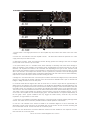
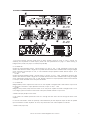
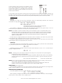
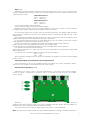
User Manual
D series
Antes de utilizar el equipo, lea la sección
“Precauciones de seguridad” de este manual.
Conserve este manual para futuras consultas.
Before operating the device, please read the
“Safety precautions” section of this manual.
Retain this manual for future reference.
CONTENTS
SAFETY PRECAUTIONS
3
WARRANTY
4
DECLARATION OF CONFORMITY
5
6 to 7
INTRODUCTION
8
FRONT PANEL
9 to 11
REAR PANEL
SPECIFICATIONS
12
APPENDIX I: Power Consumption and Thermal Emissions (D-100)
13
APPENDIX II: T LINE - Operating Instructions
14
APPENDIX III: Instructions for using D-10 with 100V/70V line transformers
15
Manual del Usuario / D series amplifiers/ User’s Manual
D series
Precauciones de Seguridad
Safety Precautions
Amplificadores profesionales / Professional power amplifiers
Conserve y lea estas instrucciones.
Respete y siga todas las advertencias.
El signo de exclamación en un triángulo equilátero pretende
alertar al usuario de instrucciones operativas y de mantenimiento
(reparación) en la literatura que acompaña al aparato.
ADVERTENCIA: Los aparatos de CLASE I se deben conectar a
una toma de corriente eléctrica con conexión a tierra.
Keep these instructions. Read these instructions.
Heed all warnings. Follow all instructions.
The exclamation point within an equilateral triangle is intended to
alert the user of important operating and maintenance (servicing)
instructions in the literature accompanying the appliance.
WARNING: Apparatus with CLASS I construction shall be
connected to a MAINS socket outlet with a protective earthing
connection.
El rayo con punta de flecha dentro de un triángulo equilátero
pretende alertar al usuario de la presencia de voltajes peligrosos
no aislados dentro de la envolvente del producto, que puede ser
de magnitud suficiente para constituir un riesgo de descarga
eléctrica para las personas.
ADVERTENCIA: Para evitar lesiones, este aparato debe estar
firmemente sujeto al bastidor, de conformidad con las
instrucciones de instalación.
El cableado exterior conectado a estos terminales requiere de su
instalación por una persona instruida y el uso de cables flexibles
preparados.
The lightning flash with arrowhead symbol within an equilateral
triangle is intended to alert the user to the presence if
uninsulated “dangerous voltage” within the product's enclosure
that may be of sufficient magnitude to constitute a risk of electric
shock to persons.
WARNING: To prevent injury, this apparatus must be securely
attached to the rack in accordance with the installation
instructions.
The connected outer wiring to these terminals requires of its
installation by an instructed person and the use of a flexible the
cable already prepared.
No exponga este equipo a la lluvia o humedad. No use este
aparato cerca del agua (piscinas y fuentes, por ejemplo). No
exponga el equipo a salpicaduras ni coloque sobre él objetos
que contengan líquidos, tales como vasos y botellas. Equipo IP20. Limpie con un paño seco. No use limpiadores con
disolventes.
Do not expose this device to rain or moisture. Do not use this
apparatus near water (for example, swimming pools and
fountains). Do not place any objects containing liquids, such as
bottles or glasses, on the top of the unit. Do not splash liquids
on the unit. IP-20 equipment. Clean only with a dry cloth. Do not
use any solvent based cleaners.
No instale el aparato cerca de fuentes de calor tales como
radiadores, calefactores, estufas u otros aparatos que produzcan
calor. No bloquee las aberturas de ventilación, e instalar de
acuerdo con las instrucciones del fabricante. Los ventiladores de
refrigeración succionan aire fresco del frontal y sale caliente por
la parte trasera de la unidad a través de las rejillas de ventilación.
La parte delantera y trasera del amplificador debe tener una
exposición al aire libre (por ejemplo, en un rack las puertas
delanteras y traseras abiertas), con cámara de aire de 2 cm a los
lados y la parte superior. SI AL AIRE NO SE LE PERMITE
ESCAPAR POR ATRÁS, SE SOBRECALENTARÁ LA UNIDAD.
Tenga cuidado al montar otro equipo en el mismo rack.
Diseñado para funcionar entre 15ºC y 35ºC, con el 75% de
humedad relativa máxima.
Do not install near any heat sources such as radiators, heat
registers, stoves or other apparatus that produce heat.
Do not block any ventilation openings, install in accordance with
the manufacturer's instructions.
The cooling fans suck cool air in through the front and blow hot
air out at the rear of the unit through the ventilating grills. The
front and rear of the amplifier should have free exposure to the
air (i.e. in a rack leave the front and rear doors off), with 2cm air
gap at the sides and top. IF AIR IS NOT ALLOWED TO ESCAPE
FROM THE REAR, OVER-HEATING WILL OCCUR. Take care
when mounting other equipment in the same rack.
Working temperature ranges from 15ºC to 35ºC with a relative
humidity of 75%.
Desconecte este aparato durante tormentas eléctricas,
terremotos o cuando no se vaya a emplear durante largos
periodos.
Tenga en cuenta que la tensión nominal de alimentación es el
valor indicado en la etiqueta, con un rango ±10% de ese valor
(según IEC 60065:2001).
Proteja el cable de alimentación de ser pisado o aplastado,
especialmente en los enchufes, receptáculos y en el punto en el
que salen del aparato. Confíe las reparaciones a personal
cualificado. Se requiere servicio cuando el aparato ha sido
dañado de alguna manera, como por ejemplo si el cable de
alimentación o el enchufe está dañado, se ha derramado líquido
o han caído objetos dentro del aparato, el aparato ha sido
expuesto a la lluvia o la humedad, no funciona con normalidad o
se ha caído. El interruptor de alimentación deberá permanecer
fácilmente accesible. Para desconectar completamente este
aparato de la red eléctrica, desconecte el cable de alimentación
del interruptor de corriente principal. Esta unidad está equipada
con un cable de alimentación de 3 hilos. Por razones de
seguridad,
LA
CONEXIÓN
A
TIERRA
NO
DEBE
DESCONECTARSE EN NINGUNA CIRCUNSTANCIA.
Unplug this apparatus during ligtning storms, earthquakes or
when unused for long periods of time.
Take into account that the nominal AC voltage is the value shown
in the equipment ±10% (according to IEC 60065:2001).
Protect the power cord from being walked on or pinched
particularly at plugs, convenience receptacles and the point
where they exit from the apparatus.
Refer all servicing to qualified service personnel. Servicing is
required when the apparatus has been damaged in any way,
such as if the power-supply cord or plug is damaged, liquid has
been spilled or objects have fallen into the apparatus, the
apparatus has been exposed to rain or moisture, does not
operate normally, or has been dropped.
The mains circuit breaker shall remain readily accessible.
To completely disconnect this equipment from the AC mains,
disconnect the power cord from the mains circuit breaker.
This unit is fitted with a 3-wire power cord. For safety reasons,
THE EARTH LEAD SHOULD NOT BE DISCONNECTED IN ANY
CIRCUMSTANCE.
Cuando la unidad esté montada en un rack y permanentemente
conectada a red debe ser instalada con un conector de fácil
acceso o con un dispositivo de desconexión omnipolar con al
menos 3 mm de distancia entre sus contactos. El interruptor de
los amplificadores sólo afecta a uno de los polos de la red
eléctrica, por tanto, en las unidades con un cable desmontable
el dispositivo de desconexión de red (por ejemplo, el enchufe o
la conexión a red), debe ser fácilmente accesible para poder
estar completamente desconectado de la red. Sin embargo, en
unidades con cable fijo deberá usar un dispositivo de
desconexión externo (antes descrito). La instalación deberá
seguir todas las normas de instalación vigentes.
Utilice sólo accesorios (por ejemplo, soportes o racks)
recomendados por el fabricante. Cuando se utiliza un rack o un
carro de transporte, tenga cuidado al mover la combinación
carro / aparato para evitar lesiones causadas por un vuelco.
Where the amplifier is mounted in a rack and permanently
connected to the mains, then the rack should be installed with a
readily accessible connector or an ALL POLE circuit breaker with
3mm breaking distances.
The mains switch on the amplifiers only switches one pole of the
mains supply, therefore for units with a detachable cord to be
fully disconnected from the mains, the mains disconnect device
(ie mains plug or mains coupler) should remain readily operable.
For units with a fixed mains lead the external all pole circuit
breaker with 3mm breaking distances is the disconnect device
and therefore the installation of the amplifier shall be carried out
in accordance with all the applicable installation rules.
Only use attachments/accessories specified by the manufacturer.
Use only with the cart, tripod, bracket or table specified by the
manufacturer, or sold with the apparatus. When a cart is used,
use caution when moving the cart/apparatus combination to
avoid injury from a tip over.
Este símbolo indica que el presente producto no puede ser
tratado como residuo doméstico normal, sino que debe
entregarse en el correspondiente punto de recogida de equipos
eléctricos y electrónicos.
This symbol on the product indicates that this product should
not be treated as household waste. Instead it shall be handed
over to the appicable collection point for the recycling of
electrical and electronic equipment.
Manual del Usuario / D series amplifiers/ User’s Manual
3
GARANTÍA
Todos nuestros productos están garantizados por un periodo de 24
meses desde la fecha de compra.
Las garantías sólo serán válidas si son por un defecto de
fabricación y en ningún caso por un uso incorrecto del producto.
Las reparaciones en garantía pueden ser realizadas,
exclusivamente, por el fabricante o el servicio de asistencia técnica
autorizado.
Otros cargos como portes y seguros, son a cargo del comprador
en todos los casos.
Para solicitar reparación en garantía es imprescindible que el
producto no haya sido previamente manipulado e incluir una
fotocopia de la factura de compra.
WARRANTY
All D.A.S. products are warrantied against any manufacturing defect
for a period of 2 years from date of purchase.
The warranty excludes damage from incorrect use of the product.
All warranty repairs must be exclusively undertaken by the factory
or any of its authorised service centers.
To claim a warranty repair, do not open or intend to repair the
product.
Return the damaged unit, at shippers risk and freight prepaid, to
the nearest service center with a copy of the purchase invoice.
4
Manual del Usuario / D series amplifiers/ User’s Manual
DECLARACIÓN DE CONFORMIDAD
DECLARATION OF CONFORMITY
D.A.S. Audio, S.A.
C/ Islas Baleares, 24 - 46988 - Pol. Fuente del Jarro - Valencia. España
(Spain).
Declara que los amplificadores de la serie D:
Declares that D series amplifiers:
Cumple con los objetivos esenciales de las Directivas:
Abide by essential objectives relating Directives:
l
Directiva de Baja Tensión (Low Voltage Directive)
2006/95/CE
l
Directiva de Compatibilidad Electromagnética (EMC)
2004/108/CE
l
Directiva RoHS
2002/95/CE
l
Directiva RAEE (WEEE)
2002/96/CE
Y es conforme a las siguientes Normas Armonizadas Europeas:
In accordance with Harmonized European Norms:
l
EN 60065:2002
Audio, video and similar electronic
apparatus. Safety requirements.
l
EN 55103-1:1996 Electromagnetic compatibility.
Product family standard for audio, video, audiovisual and entertainment lighting control apparatus
for professional use. Part 1:Emission.
l
EN 55103-2:1996 Electromagnetic compatibility.
Product family standard for audio, video, audiovisual and entertainment lighting control apparatus
for professional use. Part 2:Immunity.
Manual del Usuario / D series amplifiers/ User’s Manual
5
INTRODUCTION
INSTALLATION: ELECTRICAL
The amplifier has been manufactured to
comply with your local power supply requirements,
but before connecting the unit to the supply,
ensure that the voltage (printed on the rear panel)
is correct, and that a mains fuse of the correct
type and rating has been fitted.
Make sure power outlets conform to the power
requirements listed on the back of the unit.
Damage caused by connecting to improper AC
voltage is not covered by the warranty.
SAFETY WARNING
Apparatus with CLASS I construction shall be
connected to a MAINS socket outlet with a
protective earthing connection.
Where a MAINS plug or appliance coupler is
used as the disconnect device, it should remain
readily operable.
Where the amplifier is mounted in a rack and
permanently connected to the mains, then the
rack should be installed with a readily accessible
connector or an ALL POLE circuit breaker with
3mm breaking distances.
This unit is fitted with a 3-wire power
connector. For safety reasons, THE EARTH LEAD
SHOULD NOT BE DISCONNECTED IN ANY
CIRCUMSTANCE.
If
ground
loops
are
encountered consult the section on input
connections later in this manual.
WHERE A FIXED MAINS LEAD IS FITTED,
THE WIRING COLOURS ARE:
230V AREAS:
EARTH = GREEN AND YELLOW
NEUTRAL = BLUE
LIVE = BROWN
120V AREAS:
EARTH = GREEN
NEUTRAL = WHITE
LIVE = BLACK
TO PREVENT THE LIKELIHOOD OF SHOCK
OR FIRE HAZARD, DO NOT EXPOSE THE UNIT
TO RAIN OR MOISTURE.
DO NOT PLACE
OBJECTS CONTAINING LIQUID ON TOP OF THE
APPARATUS.
TO AVOID ELECTRICAL SHOCK DO NOT
REMOVE COVERS. REFER ALL SERVICING TO
QUALIFIED PERSONNEL.
DO NOT USE THE UNIT OF THE ELECTRICAL
POWER CORD IS FRAYED OR BROKEN. The
power supply cords should be routed so that they
are not likely to be walked on or pinched by items
placed upon or against them, paying particular
attention to cords and plugs and the point where
they exit from the appliance.
ALWAYS OPERATE THE UNIT WITH THE AC
GROUND
WIRE
CONNECTED
TO
THE
ELECTRICAL SYSTEM GROUND. Precautions
should be taken so that the means of grounding of
a piece of equipment is not defeated.
6
DO NOT REMOVE THE LID. Removing the lid
will expose you to potentially dangerous voltages.
There are no user serviceable parts inside.
ESD strikes to the unit's front panel that are in
excess of 4000 volts may cause disturbance to
the status LEDs on the unit. This will not affect
audio performance and will be corrected on the
next power up cycle.
INSTALLATION: MECHANICAL
To ensure that this equipment performs to
specification, it should be mounted in a suitable
rack or enclosure as described below. Like all high
power amplifiers, it should be kept away from
other equipment which is sensitive to magnetic
fields. Also, this amplifier may suffer a substantial
reduction in performance if it is subjected to, or
mounted close to equipment which radiates high
RF fields.
Warning: To prevent injury, this apparatus must
be securely attached to the rack in accordance
with the installation instructions.
When mounting the amplifier in a rack or
enclosure:
Be aware that ...
THE FRONT PANEL IS NOT CAPABLE OF
SUPPORTING THE UNIT ON ITS OWN.
Make sure that the rear of the unit is adequately
supported. The brackets which are supplied fit
standard 19 inch (483mm) rack mounting
systems.
ENSURE THERE IS ADEQUATE VENTILATION.
The cooling fans suck cool air in through the front
and blow hot air out at the rear of the unit through
the ventilating grills. The front and rear of the
amplifier should have free exposure to the air (i.e.
in a rack leave the front & rear doors off), with 2cm
air gap at the sides.
IF AIR IS NOT ALLOWED TO ESCAPE FROM
THE REAR, OVER-HEATING WILL OCCUR.
Take care when mounting other equipment in the
same rack.
Make sure that the rack unit has a separate
earth connection (technical earth).
The high frequency resonant converters in the
D-100 amplifiers have been designed to have very
low radio frequency (RF) emissions; however even
these low level emissions can cause interference
with other equipment.
In order for this to be minimised, the amplifier
should be mounted in a metal rack enclosure,
which should have a separate (technical) Earth.
Alternatively a separate earth should be attached
to the amplifier at the rear rack mounting bracket.
Manual del Usuario / D series amplifiers/ User’s Manual
Dynamic Amplifier
Measurements
Performance
The D-100 is the very latest example of a
'dynamic amplifier'. This new 'breed' of power
amplifiers provide very high peak power levels in a
much smaller, and lighter, package than previously
possible with conventional amplifiers.
They are designed specifically for today's high
power audio installations, which use multiple
speakers with electronic crossovers or speaker
controllers. These systems can handle very high
transient signals that far exceed their RMS power
rating. The D-100 amplifiers have been designed
to match this requirement and can deliver huge
levels of power for short durations.
In order to protect themselves and the
loudspeakers that they are driving, continuous
signals such as sine waves, are automatically
detected and reduced (ramped down) to a safe
level.
When trying to measure the power output
however, continuous signals will give totally
incorrect results. A dynamic signal, such as a tone
burst, should be used and the levels measured by
monitoring the waveform on an oscilloscope. The
power envelope can then be accurately measured.
Our power output figures are measured using
signals with known Crest Factors and are quoted
at the rear of this manual and on our website.
Please refer to the technical area of our
website for further information.
Notes and Switching On
Read all documentation before operating your
equipment and retain all documentation for future
reference.
Do not spill water or other liquids into or on the
unit and do not operate the unit while standing in
liquid.
Do not block fan intake or rear ventilation
outlets or operate the unit in an environment that
could impede the free flow of air around the unit.
If the unit is used in an extremely dusty or
smoky environment, it should be cleaned of any
collected debris at regular intervals.
It is important that the power output of your
amplifier is matched to the power handling
capacity of your loudspeaker. If not, damage to
the loudspeaker could occur.
Other LEDs may remain illuminated depending
upon rear panel switch settings and input
connections. If the A/P LED does not extinguish
after 5 seconds the unit may be faulty or some
external connections may be incorrect or
inappropriate. If this occurs you should power
down the unit and remove all external connections
(except for the mains power supply) and repeat
the power up sequence. If the problem persists
please contact us.
Maintenance
These maintenance instructions are for use by
qualified personnel only. Before any routine
maintenance, please ensure that your amplifier is
disconnected from the mains supply!
The filter behind the air intake apertures on the
front of your amplifier should be cleaned or
replaced periodically, e.g. 12-24 months. (Filters in
amplifiers located in more 'dirty' atmospheres may
require more frequent maintenance).
The filter should be 'dry' cleaned, using a
vacuum cleaner preferably. Running the unit
without a filter is not recommended unless it is
within a 'clean room'. Replacement filter material
is available.
If the fan vents on the rear of the amplifier
develop a build-up of dust/debris on the finger
guards, they can be cleaned with a dry paintbrush
and a vacuum cleaner.
The casework of the amplifier may be cleaned
with a lightly dampened cloth – do not use any
solvents as they will damage the paint finish and
could remove printing.
If you have any doubts about carrying out
maintenance, please refer to a service engineer or
contact your local dealer.
Switching On…
At 'switch-on' the protection circuit will initially
activate whilst the circuits stabilise, indicated by
the red A/P LED illuminating, in addition to various
other LEDs. After a few seconds the red A/P LED
will extinguish indicating a satisfactory working
condition.
Manual del Usuario / D series amplifiers/ User’s Manual
7
FRONT PANEL
2
6
7
5
1
D-10
4
3
7
1
2
6
3
D-20
5
1 2 9
4
5 4
7
D-100
3
6
8
1: Power Switch: This single pole switch turns the amplifier fully off (but does NOT isolate it from the mains
supply).
2: Power LED: This indicates when the amplifier is active. This does NOT indicate the presence of a mains
supply when the power switch is OFF.
3: Attenuation Controls: These are analogue controls allowing precise level settings. Note that in bridged
(mono) mode some controls may be inactive.
4: A/P (Auto Protect) LED: If a condition exists, either internally or externally, that could cause damage to
either the amplifier or the speakers, the protection circuit will disengage the outputs and the A/P LED will
illuminate. The amplifier will continue to be monitored and depending on the type of fault, will either reset
after the fault has cleared or require manual resetting by switching off at the mains switch and then on again
after a few seconds. If the outputs are shorted or if DC is present, the protection circuit will disengage the
outputs and the A/P LED will illuminate. Temperature related faults will reset if the unit has cooled sufficiently.
Output short circuits will require manual reset after clearing the fault.
5: Bridge LED: This illuminates when a channel pair have been switched into bridged (mono) mode (channel
A+B or C+D). Note that the partner channel’s LEDs and controls are disabled when a pair of channels are
bridged. Bridge switches are on the rear panel.
6: The D-10 and D-20 have Signal LEDs that are active from a minimum output level of approximately 10
Watts and are an indication only of signal presence. The D-100 has Signal Meter and OCM indicators: LED
bar graphs show instantaneous level on each channel to indicate proximity to the limiter threshold. Note that
if the PRC system is in operation on any channel, this will affect the readout shown on the respective meter.
The red LED in the meter will illuminate when the limiter threshold has been reached and limiting is occurring.
The output current monitor (OCM) may activate to limit the output current of the amplifier channel - this can
occur even if the amplifier has not reached clipping point. The OCM indicator can operate independently of
the bar graph meter. Typical conditions that may trigger the OCM circuitry would be very low load
impedance, or high subsonic or VHF levels.
7: Limit LEDs: The amplifiers incorporate signal limiters, which are preset to prevent clipping with high levels
of drive. The amber LEDs on the front panel illuminate to indicate operation of the limiters.
8: Link LED: This indicates if the channel is linked to its immediate neighbour. If this is illuminated, the
attenuation control of the channel to the immediate right will not function as both channels are being fed
from the left hand channel. The link switches are on the rear panel.
9: PRC LED: This illuminates if the Power Reduction Control has been enabled on the respective channel.
PRC switches are on the rear panel.
8
Manual del Usuario / D series amplifiers/ User’s Manual
REAR PANEL
4
7
6
1
2
3
6
3
4
8
9
4
2
1
D-10
5
D-20
1
2
5
5
3
5
D-100
1: Input XLR sockets: Connect signal inputs to these sockets, wired pin 2 hot, 3 cold, 1 ground. For
sensitivity and impedance of these inputs, please see the specifications on page 11. When running in
bridged (mono) mode, only input A is used (except D-100).
2: D-10 & D-20
Channel A output Speakon socket: Normal output is on pins 1+ hot, 1- cold. Channel B's output is also
wired to this socket to enable a single NL4 to provide both channels and to facilitate easier wiring in bridged
mode. Channel B is wired pins 2+ hot, 2- cold. Channel B output Speakon socket: Normal output is on
pins 1+ hot, 1- cold.
D-100
Channel A output Speakon socket: Normal output is on pins 1+ hot, 1- cold. Channel B's output is also
wired to this socket to enable a single NL4 to provide both channels and to facilitate easier wiring in bridged
mode. Channel B is wired pins 2+ hot, 2- cold. Similarly channel C's output Speakon socket carries Channel
D's output. Check the table on the rear panel for details.
3: D-10 & D-20
Bridged (Mono) switch: Depress this switch to run the amplifier in bridged mode. Note that the output must
be taken from channel A's output Speakon connector, on pins 2+ hot, 1- cold.
D-100
Bridged (mono) switch (A+B): Press this switch to run this pair of amplifier channels in bridged mode. To run
C+D bridged, press the switch on the far left of the panel, beside channel D's input XLR.
4: Mains inlet (only D-10) & Power Cord.
5: Fan outlet: The variable speed fans suck air in through the front vents and out through the back of the
amplifier.
6: Link out XLR sockets: These are passively connected directly to their respective inputs to allow for parallel
input connections to other amplifiers. As such, they will function even if the amplifier is turned off.
7: Mains Fuse (only D-10).
Manual del Usuario / D series amplifiers/ User’s Manual
9
8: PRC switches: Each channel of the amplifier may be
power limited independently using these pairs of switches
in three stages, offering 2, 4 and 6dB of Power Reduction
Control. The settings for these switches are on the rear
panel for quick reference.
9: Link switch: Press this switch to link the input of the channel to its immediate left. Multiple channels may
be linked using these switches so, for example, to link all outputs to input A, press all three switches IN and
use input A only. The front panel attenuators will still operate independently when channels are linked.
CONNECTIONS
INPUTS
The inputs are made via 3-pin XLR connectors, which are electronically balanced and should be
connected via a high grade twin core screened cable, as follows:
PIN2 - Hot
(signal +). Signal Hot.
PIN3 - Cold (signal -). Signal Cold.
PIN1 - Screen (see note).
Connected to the chassis of the unbalanced equipment
or left disconnected at the unbalanced end.
The amplifier is designed to operate with fully balanced equipment and ground loops or loss of
performance may be experienced if connected to unbalanced sources.
NOTE: This amplifier is wired to the latest industry recommendations. PIN1 is connected directly to the
chassis/mains earth. If ground loops (mains hum) are encountered remove the screen connection
from the other end of the cable and leave it open circuit. If problems persist, consult your dealer/
supplier, DO NOT TAMPER WITH OR ALTER ANY GROUND (EARTH) CONNECTIONS
INSIDE THE AMPLIFIER.
D-10 & D-20: For bridged operation input should be made to channel A only and the rear panel switch
set for bridged mode. Channel B will then be fed out of phase with channel A.
D-100: For bridged operation input should be made to channel A (or C) only and the rear panel switch
set for bridged mode for the appropriate pair of channels.
OUTPUTS
The speaker outputs are via Neutrik Speakon connectors. Only 2 of the 4 poles are used. 2 pole (NL2FC)
or 4 pole (NL4FC) connectors can be used. Terminations are as follows :
HOT Pin +1
COLD Pin -1
Additionally Channel A Speakon connector carries Channel B output on Pins +2 & -2 to allow easy biamping or bridged operation.
HOT Pin
+2
COLD Pin
-2
NOTE: 1.- Although the "cold" output terminals are nominally at 0V., they should not be joined together,
otherwise cross-talk may be introduced.
2.- Because the currents involved are very high, the speaker cables should conform to the following
minimum requirements, otherwise the losses will cause the cables to get hot and audio power will
be reduced:
D-10, 12A D-20, 16A D-100, 20A
- all into 4ohm speaker loads
NOTE: Do not connect the inputs/outputs to any other voltage source such as a battery, mains source or
power supply, regardless of whether the amplifier is turned on or off.
Do not run the output of any amplifier channel back into another channel's input and do not
parallel or series-connect an amplifier output with any other amplifier output.
LINK SOCKET (only D-10 & D-20 )
Each channel is provided with a 3-pin XLR connector marked 'LINK' which allows the input signal to be
linked to further amplifiers etc. The connections are the same as for the input XLR.
BRIDGED (MONO) OPERATION
Use centre Speakon connector marked 'BRIDGED' and connect as follows:
HOT
Pin +1 (Channel A - IN PHASE)
COLD
Pin -1 (Channel B - OUT OF PHASE)
When operating in bridged mode, the minimum impedances are doubled. The minimum load in bridged
mode is: D-10: 4 ohms, D-20: 4 ohms, D-100: 4 ohms.
10
Manual del Usuario / D series amplifiers/ User’s Manual
Only D-100:
Additionally Channel A Speakon connector carries Channel B output on Pins +2 & -2 to allow easy biamping or bridged operation using a single NL4 connector. Similarly, Channel C's Speakon connector also
carries Channel D output.
Output Connector A
Pin 2+: Hot Ch. B
Pin 2-: Cold Ch. B
Output Connector C
Pin 2+: Hot Ch. D
Pin 2-: Cold Ch. D
For bi-amped operation, connect as above.
There must be no shared connections between channels.
Negative output terminals must not be joined together as they are not both at ground potential.
Connecting them together will damage the amplifier and void the warranty!
As the currents involved are very high, and to ensure best performance, the speaker cables should be
kept as short as possible and conform to the following minimum requirements (D-100, 20A into 4 Ohm
speaker loads).
When operating the amplifier into loads of less than 4 Ohms, be aware that the current capacity of the
speaker cables will need to be increased above the values quoted here.
Do not connect the inputs/outputs to any other voltage source such as a battery, mains source or power
supply, regardless of whether the amplifier is turned on or off.
Do not run the output of any amplifier channel back into another channel's input and do not
parallel or series-connect an amplifier output with any other amplifier output.
Pairs of channels may be independently bridged – channel pair A&B, and/or channel pair C&D.
The method is the same for both channel pairs:
Supply signal to Channel A or C input only and push in the appropriate rear panel switch marked “BRG
A&B” or “BRG C&D”.
Use Channel A or C's Output Speakon connector and connect as follows:
Pin 2+: Hot
Pin 1-: Cold
When operating in bridged mode, the minimum impedances are doubled. The minimum load in bridged
mode is 4 ohms.
Changing the Gain of Your Amplifier: Internal Adjustments!
These instructions are for use by qualified personnel only. Before any routine maintenance, please
ensure that your amplifier is disconnected from the mains supply!
Gain/Sensitivity Settings (D-100)
Adjustment is by moving a link on the input PCB (PCB741) – one link for each channel. Channel
A's link is number 1, channel B's is number 2 and so on. The gain may be set to 26, 32 or 36dB
(factory setting).
Remember, setting higher gain does not change the maximum available power but changes the level of
signal input to achieve maximum power. In any case, provided that the input signal is less than 20dBu/7.7V,
the built in limiter circuit will prevent distortion within the amplifier.
The gain should be set to match the signal level from the source – mixer, equaliser etc.
Note: The gain of D-10 is fixed to 32dB. The gain of D-20 is 32dB (factory setting) or 36 dB by internal link.
Manual del Usuario / D series amplifiers/ User’s Manual
11
SPECIFICATIONS
Parameter (Units)
D-100
D-10
D-20
Output Power (per channel) (Watts) (Crest Factor of 4.8)
8 ohms
1400
450
625
4 ohms
2800
750
1150
2 ohms
3700
1150
2100
8 ohms
5300
1500
2300
4 ohms
7400
2300
4200
THD+N:(%)(4 ohms)@1kHz (@1dB below max output power) <
0,08
0,008
0,008
THD+N:(%)(4 ohms)@20Hz to 20kHz (@3dB below max output power) <
0,15
0,03
0,03
Output Power (bridged) ( Watts)
Additional Specifications
26/32/36
32
32/36
Sensitivity Options (for maximum power) (dBu):
Gain Options (dB):
16/10/6
3,5
7.5/3.5
Sensitivity Options (for maximum power) (Volts):
4.9/2.5/1.5
1,2
1.8/1.2
±0.5
+0 / -0.5
+0 / -0.5
Frequency Response - 20Hz to 20kHz (dB):
Input Impedance - Active balanced (k ohms):
20
>60
Input CMRR (dB):
Hum & Noise (dB below max output):
Damping Factor: into 8 ohms:
Output Circuitry:
-105
-104
>200 @100Hz
D
AB
AB
Power Consumption: Nominal @ 240v (4 ohms)(A):
7
1,9
2,8
Power Consumption: Nominal @ 120v (4 ohms)(A):
14
3,8
5,6
Dimensions (mm): H x W x D:
88x482x428
Dimensions (in): H x W x D:
3,5x19x16,9
88x482x460
3,5x19x18,2
Weight: (Kg):
12
13,8
20,42
Weight: (lb):
26,4
30,36
44,92
Product improvement through research and development is an ongoing process at D.A.S.
All specifications are subject to change without notice.
12
-106
>400 @1kHz
Manual del Usuario / D series amplifiers/ User’s Manual
APPENDIX I
Power Consumption and Thermal Emissions: D-100
Mains
(V)
240
240
240
120
120
120
Load
(R)
8
4
2
8
4
2
Current Draw
(A)
No Sig’l
Light
Average
2.1
3.0
2.1
3.9
2.1
Thermal Emissions
(W)
Heavy
No Sig’l
Light
Average
Heavy
4.5
8.3
504
528
566
660
7.0
14.4
504
551
628
816
4.5
8.6
19.1
504
564
668
936
4.2
6.0
9.0
16.6
504
528
566
660
4.2
7.8
14.0
28.8
504
551
628
816
4.2
9.0
17.2
38.2
504
564
668
936
No Sig'l = Quiescent, Light = Crest Factor of 7.8(18dB),
Average = Crest Factor of 4.8(14dB), Heavy = Crest Factor of 2.8(9dB)
For details of measurement methods please refer to the Technical Support area of our website.
PRC Settings and Maximum Output: D-100
Power Reduction Control Setting
Maximum Power into 8 ohms (W)
-2dB PRC
-4dB PRC
-6dB PRC
Maximum Power into 4 ohms (W)
-2dB PRC
-4dB PRC
-6dB PRC
Maximum Power into 2 ohms (W)
-2dB PRC
-4dB PRC
-6dB PRC
Per Channel
1400
980
560
310
Bridged Pair
5300
3700
2100
1175
2800
1950
1110
620
7400
5160
2940
1640
3700
2580
1470
820
N/A
N/A
N/A
N/A
Manual del Usuario / D series amplifiers/ User’s Manual
13
APPENDIX II
T LINE - OPERATING INSTRUCTIONS (Only D-10)
The T Line chassis can be configured with up to 4 transformers of 500W at 100V output, 4 ohms input.
Other specifications (70V/50V) are available to special order.
The power rating of each channel is printed on the rear panel.
The connections are via 4-pole SPEAKON connectors (NL4FC).
INPUTS (4 ohms) are:
OUTPUTS (100V) are:
+1 = HOT, -1 = COLD
+2 = HOT, -2 = COLD
THERE ARE NO USER-SERVICEABLE PARTS INSIDE AND NO MAINTENANCE IS REQUIRED.
IN THE EVENT OF A FAILURE, REFER TO A QUALIFIED SERVICE ENGINEER.
Parts are available from D.A.S.Audio, S.A.
TECHNICAL SPECIFICATION
T LINE
Rated power handling
@ input impedance - 4W
500W
Output impedance rated
@ 100V (Standard)
@ 70V (Special)
@ 50V (Only)
20.0W
9.8W
5.0W
Frequency response
Distortion (THD)
Weight (each)
50Hz-16kHz
50Hz-16kHz
Chassis only
500W transformer
± 1dB
<0.03%
12kgs
2.8kgs
Dimensions (mm) - 2U
88 x 482 x 428
When mounting the amplifier in a rack or enclosure, ensure that :The rear of the unit is adequately supported. The brackets which are supplied fit standard 19 inch
(483mm) rack mounting systems. THE FRONT PANEL IS NOT CAPABLE OF SUPPORTING THE UNIT ON
ITS OWN.
(The general D-10 safety warnings, precautions and service advice also apply to the T LINE.)
14
Manual del Usuario / D series amplifiers/ User’s Manual
APPENDIX III
INSTRUCTIONS FOR USING D-10 AMPLIFIERS WITH 100V/70V LINE TRANSFORMERS
Frequency response
It is necessary to provide some low frequency roll off to prevent the possibility of the line transformer
saturating.
On the D-10 the roll off is included on the main board as standard. To bring the 63 Hz roll off into circuit,
remove the 4 jumper links at 'hpf'.
The response must be at least -3dB at 70 Hz and roll off at minimum 12dB per octave.
LINE TRANSFORMER LEAD OUTS
500W single 100V winding:
Primary:
Secondary:
Orange = +ve, Black = -ve (4 ohms)
Yellow = +ve, Grey = -ve (100V)
Blue = centre tap, for monitoring purposes only
Note:
D-100 will give you 100V line out at the terminals.
D-20 will give you 70V line out at the terminals.
Manual del Usuario / D series amplifiers/ User’s Manual
15
D.A.S. AUDIO, S.A.
C/. Islas Baleares, 24
46988 Fuente del Jarro
Valencia, SPAIN
Tel. 96 134 0525
Tel. Intl. +34 96 134 0860
Fax 96 134 0607
Fax Intl. +34 96 134 0607
D.A.S. AUDIO OF AMERICA, INC.
Sunset Palmetto Park
6816 NW 77th Court.
Miami, FL. 33166 - U.S.A.
TOLL FREE: 1-888DAS4USA
Tel. +1 305 436 0521
Fax +1 305 436 0528
UM_D_AMP_01_EN
www.dasaudio.com
D.A.S. AUDIO ASIA PTE. LTD.
25 Kaki Bukit Crescent #01-00/02-00
Kaki Bukit Techpark 1
Singapore 416256
Tel. +65 6742 0151
Fax +65 6742 0157