1
AM844D
English / Español / 简体中文
COMPACT MIXERS
MEZCLADORAS COMPACTAS
小型调音台
AM844D
User’s Manual
Manual del Usuario
使用手册
AM844D
COMPACT MIXERS
MEZCLADORAS COMPACTAS
小型调音台
CONTENTS
CONTENIDO
目录
ININTRODUCTION....................4
INTRODUCCIÓN.............................13
简介...............................22
FEATURES.................................4
CARACTERÍSTICAS.......................13
特色...............................22
GETTING STARTED..................4
COMENZANDO...............................13
准备工作........................22
CHANNEL SETUP......................4
CONFIGURACIÓN DEL CANAL......13
声道设置........................22
MAKING CONNECTIONS.........5
HACIENDO CONEXIONES.............14
连接工作........................23
CONTROLS AND SETTINGS.....6
CONTROLES Y CONFIGURACIONES.15
控制和设置.....................24
DIGITAL EFFECT ENGINE........8
MOTOR DE EFECTO DIGITAL........17
数位效果处理控制..........25
MASTER SECTION....................8
SECCIÓN MASTER.........................17
控制面板........................25
SPECIFICATIONS....................10
ESPECIFICACIONES......................19
规格...............................27
DIGITAL EFFECT TABLE..........29
TABLA DE EFECTO DIGITAL..........29
数位效果表....................29
APPLICATION..........................30
APLICACIÓN...................................30
应用...............................30
DIMENSION.............................32
DIMENSION.....................................32
尺寸...............................32
BLOCK DIAGRAM....................33
DIAGRAMA DE BLOQUE.................33
线路图............................33
Phonic preserves the right to improve or alter any information within this document without prior notice
Phonic se reserva el derecho de mejorar o alterar cualquier información provista dentro de este documento sin previo aviso
PHONIC保留不预先通知便可改变或更新本文件权利
V1.0 12/19/2008
IMPORTANT SAFETY INSTRUCTIONS
The apparatus shall not be exposed to dripping or splashing and that no objects
with liquids, such as vases,
shall be placed on the apparatus. The MAINS plug is used as the disconnect device, the disconnect device shall
remain readily operable.
Warning: the user shall not place this apparatus in the
can be easily accessible.
area during the operation so that the mains switch
1. Read these instructions before operating this
apparatus.
CAUTION
2. Keep these instructions for future reference.
RISK OF ELECTRIC SHOCK
DO NOT OPEN
3. Heed all warnings to ensure safe operation.
4. Follow all instructions provided in this document.
5. Do not use this apparatus near water or in locations
where condensation may occur.
6. Clean only with dry cloth. Do not use aerosol or liquid
cleaners. Unplug this apparatus before cleaning.
7. Do not block any of the ventilation openings. Install
in accordance with the manufacturer’s instructions.
8. Do not install near any heat sources such as radiators,
heat registers, stoves, or other apparatus (including
.
9. Do not defeat the safety purpose of the polarized or
grounding-type plug. A polarized plug has two blades
with one wider than the other. A grounding type plug
has two blades and a third grounding prong. The wide
blade or the third prong is provided for your safety. If
the provided plug does not into your outlet, consult
an electrician for replacement of the obsolete outlet.
10. Protect the power cord from being walked on or
pinched particularly at plug, convenience receptacles,
and the point where they exit from the apparatus.
11. Only use attachments/accessories
manufacturer.
by the
12. Use only with a cart, stand, tripod, bracket, or
table
by the manufacturer, or sold with
the apparatus. When a cart is used, use caution
when moving the cart/apparatus
combination to avoid injury from tipover.
13. Unplug this apparatus during lighting
storms or when unused for long
periods of time.
14. Refer all servicing to
service personnel.
Servicing is required when the apparatus has been
damaged in any way, such as power-supply cord or
plug is damaged, liquid has been spilled or objects
have fallen into the apparatus, the apparatus has
been exposed to rain or moisture, does not operate
normally, or has been dropped.
CAUTION: TO REDUCE THE RISK OF ELECTRIC SHOCK,
DO NOT REMOVE COVER (OR BACK)
NO USER SERVICEABLE PARTS INSIDE
REFER SERVICING TO QUALIFIED PERSONNEL
The lightning flash with arrowhead symbol, within an
equilateral triangle, is intended to alert the user to the
presence of uninsulated “dangerous voltage” within the
product’
magnitude to constitute a risk of electric shock to persons.
The exclamation point within an equilateral triangle is intended to alert the user to the presence of important operating and maintenance (servicing) instructions in the literature
accompanying the appliance.
WARNING: To reduce the risk of
or electric shock, do
not expose this apparatus to rain or moisture.
CAUTION: Use of controls or adjustments or performance
of procedures other than those
may result in
hazardous radiation exposure.
INTRODUCTION
GETTING STARTED
Thank you for choosing one of Phonic’s many quality compact
mixers. The brand new AM844D Mixers – designed by the ingenious engineers that have created a variety of mixers fantastic
in style and performance in the past – display similar proficiency
that previous Phonic products have shown; with more than a
few refinements, of course. Featuring full gain ranges, amazingly
low distortion levels, and incredibly wide dynamic ranges, these
amazing mixers are bound to make a big splash in the World of
mixing.
1.
Ensure all power is turned off on the AM844D Mixer. To totally ensure this, the AC cable should not be connected to
the unit.
2.
All faders and level controls should be set at the lowest level
and all channels switched off to ensure no sound is inadvertently sent through the outputs when the device is switched
on. All levels should be altered to acceptable degrees after
the device is turned on.
We know how eager you are to get started – wanting to get the
mixer out and hook it all up is probably your number one priority right now – but before you do, we strongly urge you to take
a look through this manual. Inside, you will find important facts
and figures on the set up, use and applications of your brand
new mixer. If you do happen to be one of the many people who
flatly refuse to read user manuals, then we just urge you to at
least glance at the Instant Setup section. After glancing at or
reading through the manual (we applaud you if you do read the
entire manual), please store it in a place that is easy for you to
find, because chances are there’s something you missed the first
time around.
3.
Plug all necessary instruments and equipment into the
device’s various inputs as required. This may include line
signal devices, as well as microphones and/or guitars, keyboards, etc.
4.
Plug any necessary equipment into the device’s various
outputs. This could include Amplifiers, active speakers or
monitors, signal processors, and/or recording devices.
5.
Plug the supplied AC cable into the AC inlet on the back of
the device ensuring the local voltage level is identical to that
required on your device.
6.
Plug the supplied AC cable into a power outlet of a suitable
voltage.
FEATURES
7.
Turn the power switch on.
●
Audiophile-Quality & ultra low noise
●
●
8 Mic/Line channels with inserts and phantom power
CHANNEL SETUP
4 stereo channels with 4-band EQ
●
1.
4 true subgroups with main L and R routing switches and
double-bused outs
To ensure the correct audio levels of each input channel is
selected, every channel should first be switched off and all
faders set to 0.
●
10 mic preamps with +48V phantom power
2.
●
Direct outputs for multi-track recording
●
3-band EQ with swept mid-range plus low cut on each mono
channel
Choose the channel that you wish to set the level of, and ensure that channel has a signal sent to it similar to the signal
that will be sent when in common use. For example, if the
channel is using a microphone, then you should speak or
sing at the same level the performer normally would during
a performance. If a guitar is plugged into that channel, then
the guitar should also be used as it normally would be.
3.
Press the Solo button of the channel, and engage the “level
set” button next to the level meter, allowing you to see the
PFL audio signal level in the level meter.
4.
●
18dB/oct, 75Hz low cut filter on each mic channels
●
●
4 aux sends, aux 1 & 2 with Pre/Post switch
●
+4/-10 level matching on Ch9/10, Ch11/12 stereo line in for
expanded applications.
●
32/40-bit digital stereo 100-effect processor with tap control
plus test tone generator and foot switch on/off control
Set the gain of the selected channel to a level that ensures
the audio level is around 0 dB, as indicated by the level
meter.
Control Room and Phones outputs with multi-input sources
select function
5. This channel is now ready to be used; you can stop making
the audio signal.
Built-in switching power supply with universal connector,
100-240VAC, 50/60Hz
6.
To activate the channel, release the Solo button and engage
the channel’s on button and press the 1/2, 3/4 or L/R routing
buttons, allowing the signal to be sent to the corresponding
destinations.
7.
You should now select the next channel to set and go back
to follow steps 1 through 6.
●
●
●
4 stereo aux returns, 2 with effect to monitor
Rack-mounting kit included
AM844D
MAKING CONNECTIONS
1
Channel Inputs
1. XLR Jacks
These jacks accept XLR inputs for balanced signals. They can be used in conjunction with microphones such as professional condenser, dynamic or ribbon
microphones - with standard XLR male
connectors. With low noise preamplifiers, these inputs serve for crystal clear
sound replication.
NB. When using an unbalanced microphone,
please ensure phantom power is switched off.
However, when using condenser microphones
the phantom power should be activated.
7. Phones Outputs
These output ports are suited for
use with headphones or headphone
amplifiers, allowing monitoring of the
mix. The audio level of this output
is controlled using the Control Room
/ Phones control on the front panel’s
master section.
2
8. 12V Lamp
This BNC socket allows you to attach
a 12 Volt gooseneck lamp, allowing
better visibility in areas with poor light.
3
REAR PANEL
2. Line In Jacks
These inputs accept 1/4” TRS and 1/4” TS line inputs for the addition of various music instruments – such as keyboards, drum
machines, electric guitars, as well as a variety of other electric
instruments.
4
4
MASTER SECTION
5. 2T Return
These inputs accommodate RCA connectors from such devices
as tape and CD players, PCs and other sources. The level of this
input can just adjusted using the 2T Return control on the face
of the Mixer.
6. Record Outputs
As with the 2T Inputs, these outputs will accommodate RCA connectors, able to be fed to a variety of recording devices.
5
AM844D
7
9. Direct Outs
These connections are for the direct output of the signals received by mono channels 1 through to 8, post-fader, post-EQ,
post-HPF, post-mute. They are most commonly used to connect
Multi-track recorders and they can be also used to connect your
multichannel audio to your DAW, AM 844D can also be used as
an 8-track studio mixer.
3. INS (External Device Insert Jack)
The primary use for these TRS phone jacks is for the addition of
external devices, such as dynamic processors or equalizers, to
the corresponding mono input channel. This will require a Y cord
that can send and receive signals of the mixer to and from an
external processor.
4. Stereo Channel Inputs
The AM 844D features 4 stereo input channels (channels 9
through to 16), the inputs of which differ slightly to the mono
channels. The 3-pin XLR inputs on the first two stereo inputs
are for the addition of microphones with typical XLR male inputs,
where the Line 1/4” TRS jacks are for the addition of various
stereo line level input devices, such as keyboards. If you wish
to use a monaural device on a stereo return input, simply plug
the device’s 1/4” phone jack into the left (mono) stereo input and
leave the right input bare. The signal will be duplicated to the
right due to the miracle of jack normalizing.
8
9
10. Auxiliary (AUX) Sends
These 1/4” phone jacks are the final output of line-level signal
fed from the corresponding auxiliary send mixing buses, and are
best suited for use with stage monitors. Feeding the output from
the Auxiliary outs to an amplifier - and possibly an equalizer and then to a floor monitor speaker allows artists to monitor their
own instruments or vocals whilst performing. There are four AUX
Sends at the AM 844D.
11 Main Outputs
These outputs will output the final stereo line level signal sent
from the main mixing bus. The primary purpose of the two XLR
jacks is to send the main output to external devices, which may
include power amplifiers (and in-turn, a pair of speakers), other
mixers, as well as a wide range of other possible signal processors (equalizers, crossovers, etcetera). The two 1/4” phone jacks
are able to send the Main output to external devices that may
run in parallel with the mixer. This may include additional power
amplifiers, mixers, PA systems, as well as a wide range of other
possible signal processors.
11
10
6
12. Main Insert
Located on the rear of the AM 844D, the primary use for these
TRS phone jacks is for the addition of external devices, such
as dynamic processors or equalizers, to the main L and main R
signals. This will require a Y cord that can send (pre-fader) and
receive signals to and from an external processor.
13. CTRL RM Control Room Outputs
These two 1/4” Phone Jack outputs feed the signal altered by the
Control Room level control on the face of the mixer. This output
has extensive use, as it can be used to feed the signal from the
mixer to an active monitor, for the monitoring of the audio signal
from within a booth, among many other possible uses.
14. Foot Switch Jack
The foot switch port is for the inclusion of a foot switch, used
for remote activation and deactivation of the built-in Digital Effect
processor.
12
13
14
15. Group Outs
These 1/4” phone jacks output the final feed from the Group 1/5,
2/6, 3/7 and 4/8 Faders on the main panel of the mixer. These
outputs can be sent to the Left or Right Main channels using the
corresponding selector, they can also be used to feed multi-track
records, as well as an amplifier and speakers to be used along
with the Main Speakers. Since the signal of Group 1 is mimicked
to the Group 5 output, Group 2 to Group 6 – and so forth – these
outputs can easily be used to feed an 8 track recorder by simply
connecting the Group outputs to the corresponding Multi-track input channels. Similar to if a Y-cord was built into your AM 844D!
16. AUX Returns
The 1/4” TRS AUX Return inputs are for the return of audio to
the AM 844D mixers, processed by an external signal processor.
If really needed, they can also be used as additional inputs. The
feed from these inputs can be adjusted using the AUX Return
controls on the face of the mixer. When connecting a monaural
device to the AUX Return 1, 2 and 4 inputs, simply plug a 1/4”
phone jack into the left (mono) input, and the signal will appear in
the right as well. You can use balanced and unbalanced signals.
NB. When any device is plugged into the mixer’s corresponding EFX Return inputs (AUX Return 3), the mixer’s internal digital effect engine is then
disabled.
15
16
17. Power Connector and Fuse Holder
Used for the addition of a power cable and
supply, allowing power to be supplied to the
mixer. Please use the power cable that is included with this mixer only. The Fuse holder,
located above the AC Power connector, is,
of course, for the AM 884D’s fuse. If the fuse
happens to blow, open the holder cover, and
replace the fuse with a suitable replacement
(as indicated on the fuse holder’s cover).
17
CONTROLS AND SETTINGS
Rear Panel
18. Power Switch
You can use it to turn the mixer on and off. Ensure you turn all
level controls down before activating.
19. Phantom Power Switch
When this switch is in the on position, it activates +48V of phantom power for all microphone inputs, allowing condenser microphones (well, the ones that don’t use batteries) to be used on
these channels. Activating Phantom Power will be accompanied
by an illuminated LED above the left channel Level Meter. Before turning Phantom Power on, turn all level controls to a minimum to avoid the possibility of a ghastly popping sound from the
speakers.
NB. Phantom Power should be used in conjunction with balanced microphones. When Phantom Power is engaged, single ended (unbalanced)
microphones and instruments should not be used on the Mic inputs.
Phantom Power will not cause damage to most dynamic microphones,
however if unsure, the microphone’s user manual should be consulted.
18
19
Channel Controls
20. Line/Mic Gain Control
This controls the sensitivity of the input signal of
the Line/Microphone input of mono channels, the
gain should be adjusted to a level that allows the
maximum use of the audio, while still maintaining
the quality of the feed. This can be accomplished
by adjusting it to a level that will allow the peak
indicator occasionally illuminate. On channels
9-10 and 11-12, the gain control affects the microphone input only, and on channels 13-14 and
15-16, this only affects line inputs (as there are
no microphone inputs on these channels).
20
21
21. Low Cult Filter (75 Hz)
Located on channels 1 through to 8, will activate a high-pass
filter that reduces all frequencies below 75 Hz at 18 dB per Octave, helping to remove any unwanted ground noise or stage
rumble. Stereo channels does not feature this low cut filter.
AM844D
22. +4/-10dB Buttons
Located on stereo channels 9-10 and
22
11-12, these buttons select the input
signal level, allowing the mixer to better adapt to different operating levels.
If the input source is -10 dBu (consumer audio standard), it is best to
engage the switch, allowing the signal
to be heard. If the input source is +4
dbV (professional audio standard) the
corresponding input channel’s button
should be disengaged to ensure the
integrity of the Mixer’s circuitry. If you
are unsure of the source’s operating
level, we suggest leaving the switch disengaged until you test the
source’s signal. You can then engage if necessary (if the level of
input is obviously too low).
23. High Frequency Control
Use it to give a shelving boost or cut
of ±15 dB to high frequency (12 kHz)
sounds. This will adjust the amount
of treble included in the audio of the
channel, adding strength and crispness to sounds such as guitars, cymbals, and synthesizers.
23
24
24. Middle Frequency Control
You can provide a peaking style of
boost and cut to the level of middle
frequency sounds at a range of ±15
dB with this control. The AM 844D
mixer also provides a sweep control,
allowing you to select a center fre25
quency between 100 Hz and 8 kHz.
Changing middle frequencies of an audio feed can be rather difficult when used in a professional audio mix, as it is usually more
desirable to cut middle frequency sounds rather than boost them,
soothing overly harsh vocal and instrument sounds in the audio.
The stereo channels of the AM 844D mixer feature a High-Mid
and Low-Mid control instead of the typical controls described
above. They provide a peaking style of boost and cut to middle
frequencies, where the frequencies are set at 3 kHz and 800 Hz
for the High- and Low-Mids respectively.
27. Pan / Balance Controls
This alternates the degree or level of audio that the left and
right side of the main mix should receive. On mono channels,
the PAN control will adjust the level that the left and right should
receive (pan), where as on a stereo channel, adjusting the BAL
control will attenuate the left or right audio signals accordingly
(balance).
28. On Button and Indicator
This turns the channel on, allowing the user to use the feed
from the channel’s inputs to supply the MAIN L/R, GROUP 1/2,
GROUP 3/4, AUX and EFX buses (as specified by the user, of
course). The corresponding indicator will be illuminated when
turned on.
29. 1-2, 3-4 and L-R Buttons
These handy buttons allow you to decide the audio path of the
corresponding channel. Pushing the “1/2” or “3/4” buttons allows
the signal to be sent to the Group 1/2 or 3/4 mixes respectively,
where the “L-R” allows it to be sent to the Main L/R mix.
30. Peak Indicator
This LED indicator will illuminate when the channel hits high
peaks, 6 dB before overload occurs. It is best to adjust the channel level control so as to allow the PEAK indicator to light up on
regular intervals only. This will ensure a greater dynamic range of
audio. This indicator also doubles as a Solo indicator, when the
SOLO button is engaged.
31. Solo Button
The Solo button is pushed to allow the signal of the corresponding channel to be sent to the Control Room / Phones mixing bus
(pre or post fader, depending on the properties selected by the
pre / post button, located by the Control Room / Phones source
buttons), for use with either headphones or studio monitors. This
button also allows for easier isolation of individual channel signals, ensuring setting of the input gain or tracking of audio by
sound engineers is made simpler. The Peak indicator above the
Solo button also doubles as a Peak Indicator, illuminating when
the signal reaches high peaks.
32. Channel Level Control (Fader)
This control will alter the signal level that is sent from the corresponding channel to the corresponding mixing buses.
25. Low Frequency Control
This control is used to give a shelving boost or cut of ±15 dB to
low frequency (80 Hz) sounds. This will adjust the amount of bass
included in the audio of the channel, and bring more warmth and
punch to drums and bass guitars.
26. AUX Controls
These four AUX controls alters the
signal level that is being sent to the
auxiliary 1 to 4 mixing buses, the
signal of which is suitable for connecting stage monitors, allowing
artists to listen to the music that is
being played. AUX 1 and 2 feature a
Pre/Post button, which alternates the
feed to the AUX mixing bus between
a post and pre-fader feed. AUX 3, on
the other hand, acts as an EFX send,
the signal of which can be used in
conjunction with external signal processors (which can be returned to
the mixer via the AUX return input),
or simply as an Auxiliary output. Both
the AUX 3 (EFX) and AUX 4 controls
are post fader and are sent directly
to the corresponding outputs.
AM844D
28
29
26
30
32
31
27
DIGITAL EFFECT ENGINE
33. Digital Effect Display
This 2-digital numeric display shows the program number that is
currently applied to your EFX audio signal. When you rotate the
Program control, you can scroll through different program numbers; however the display will revert back to the original program
if a new program is not selected within a few seconds. For a list
of available effects, please observe the Digital Effect Table.
34. Sig and Clip Indicators
Located within the Digital Effect Display are Clip and Sig LEDs.
The Sig LED will light up when any signal is received by the effect
processor, and the Clip LED will light up shortly before excessive
signals are dynamically clipped. If the Clip LED lights up too often, it may be advisable to turn down one or all EFX controls on
input channels to ensure the signal level is not too high.
35. Program Control
This control is used to scroll through the various effects. Turning
the control clockwise will allow users to ascend into higher program numbers, and turning it counter-clockwise will allow users
to descend into lower program numbers. Pushing this control will
apply the new effect. When a tap-delay effect is selected, pressing this control will allow users to select the tap-delay time.
By pushing the button several times, the effect processor interprets the time between last two pushes and remembers this as
the delay time, until the button is pushed again (this is kept, even
after the power is turned off). When the tap delay effect is selected, a small LED will flash within the digital effect display window
at the selected intervals.
36. Effect On Button
This button is pushed to turn the internal effect processor on or
off.
33 34
35
40. AUX Return 4 Control
This control adjusts the signal level of audio fed through to the
stereo AUX Return 4 inputs. The accompanying “C-R Phones
Only” button allows users to send the signal to the Control Room
/ Phones mixing bus for monitoring purposes.
41. Solo Returns Button
Pushing this buttons allows you to send the signal from all AUX
Returns to solo mixing bus (which is, intern, send to the Control
Room / Phones mixing bus). When the Solo is activated, the corresponding LED indicator will illuminate.
37
37
38
39
41
40
42. AUX Send Master Controls
These controls adjust the final level of the AUX 1, 2 and 3/4 signals (as taken from the AUX 1, 2, 3 and 4 level controls on each
channel strip), the audio of which is sent to the corresponding
AUX send outputs. The SOLO buttons accompanying these controls allow you to send the AUX send signals to the Control Room
/ Phones mixing bus for monitoring purposes.
43. AUX Solo Buttons
Pushing one or more of these buttons allows you to send the signals from the AUX 1, 2 or 3/4 mixing buses to the Control Room
/ Phones mixing bus.
36
MASTER SECTION
37. AUX Return 1 and 2 Controls
These controls adjust the signal level of audio fed through to the
stereo AUX Return inputs. The “To AUX Send 1” and “To AUX
Send 2” controls adjust the pre-fader level of the signal from the
AUX Return controls to the corresponding AUX mixing buses for
effect-to-monitor sends.
38. EFX Return Control
This control adjusts the signal level of audio fed through to stereo
AUX Return 3 inputs. If no device is plugged into the AUX Return
3 inputs, it then acts as the final level control of the built-in Digital
Effect Engine.
39. Main L/R - Group Buttons
The first of these buttons changes the destination of the signal
sent from the AUX Return 3 mixing buses between the Main L/R
and Group mixing buses. The second button works when the
user selects to send the signal “To Group”, allowing the signal to
be sent to either Group 1-2 or Group 3-4.
42
43
44. Solo Mode Button and Indicator
This button alternates the solo source signals between those of
post-fader (normal) and pre-fader feeds (level set), to be sent to
the Control Room / Phones mixing bus. When the Solo indicator,
located beside the Level Meter, is illuminated, one or more Solo
buttons has been pushed; therefore the Level meter will display
properties of the Solo signal, which is helpful with setting of channel properties. If the Solo indicator illuminates green, this means
the Solo feed is a pre-fader signal. If the solo indicator illuminates
red, the feed is post-fader. If no Solo buttons are activated, the
Control Room / Phones selected sources (Main L-R, Group 1-2,
Group 3-4 and/or 2T Return) signal properties are displayed by
the Level Meter. In this case, the Level meter will display the sum
of the selected signals.
AM844D
45. 2T Return Controls
Turning the 2T Return level control adjusts the signal level of the
feed from the 2T Return inputs. The “to Main L/R” button that accompanies this control allows users to send the 2T return signal
to the Main L-R mixing bus. When this is done, the 2T return signal is not sent to the Rec Out, as to avoid producing a feedback
loop when recorded signals are fed back into the 2T return.
46. Control Room / Phones Control
This control is used to adjust the audio level of the Control Room
and Phones feeds, for use in the monitoring and tracking of audio. The signal of the control Room / Phones mixing bus is decided by the Source Selection buttons located immediately below
this control. If no buttons are selected, the solo signal will be
used instead.
47. Control Room / Phones Source Selection
These four buttons allow users to select the various possible
sources for the Control Room and Phones outputs. By simply
pushing one of these buttons, users have the ability to monitor
the Group 1-2, Group 3-4, Main L-R and 2T return signals, either
together or individually.
Priority
Signal
High
From Solo
Low
Selected Source(s)
51. Group 1/5, 2/6, 3/7 and 4/8 Controls
These four faders are the final level control for the Group
1 to 4 audio feeds (the signals of which are doubled in
the 5 – 8 Group outputs), sent to the corresponding Group
outputs on the rear of the AM844D to feed external devices
such as effect processors, and, most commonly, multi-track
recorders. These faders can be fed a signal from the various mono and stereo channels, as well as the AUX Return
3, depending on your selections. When pushed all the way
up, these faders provide 10 dB of gain to the signal, and,
when set all the way down, effectively mute the signal.
The Group Controls also feature individual left and right
buttons, which allow you to send the various Group signals to the Main Left and Right. This can be handy when
wanting to combine the signals from different signals and
control their input levels simultaneously, then send them to
the Main L/R signal (eg. when multiple inputs are used for,
say, drums, you can combine these inputs together to be
controlled much simpler by a single fader).
52. Main L/R Fader
The Left and Right main mix is controlled with this fader
– the final level control for the Main Left and Right audio
feeds, sent to the Main L and R outputs. When pushed all
the way up, the Main L/R fader provides 10 dB of gain to
the signal, and when set all the way down, the signal is
effectively muted.
46
45
47
44
48. +48V Indicator
The internal Phantom Power will be activated
when you turn on this switch.
48
49
49. Power Indicator
The Power Indicator will light up when the power of the mixer is on; in case you weren’t too
sure.
50. Level Meter
The dual 12 segment level meter
gives an accurate indication of when
audio levels of the Main L/R signal
reach certain levels. The 0 dB indicator illuminates is approximately
equal to an output level of +4 dBu
(balanced), and the PEAK indicator
illuminates about 1.5 dB before the
signal is dynamically clipped. To
make the maximum use of audio, set
the various level controls so that it
sits steadily around 0 dB to make full
use of audio, while still maintaining
fantastic clarity.
AM844D
51
52
50
SPECIFICATIONS
Model Name
AM 844D
Inputs
Total Channels
12
Balanced Mono Mic / Line channel
8
Balanced Mic / Stereo Line channel
2
Balanced Stereo Line Channel
Aux Return
2T Input
2
4 stereo
Stereo RCA
Outputs
Main L/R Stereo
Main out with inserts
2 x 1/4” TRS, Bal. & 2 x XLR
Yes
Rec Out Stereo RCA
CTRL RM L/R
2 x 1/4” TS
Phones
Direct Out
2
Mic/Line Ch1~ Ch8
Channel Strips
12
Aux Sends
4
Pan/Balance Control
Yes
Channel Insert
Ch 1 ~ Ch 8
Volume Controls
60mm fader
Master Section
Aux Send Masters
3
Master Aux Send Solo
3
Stereo Aux Returns
4
Aux Return Assign to Subgroup
1
Effects Return to Monitor
2
Global AFL/PFL Solo Mode
Faders
Yes
4 subgroups, Main L & R
Metering
Number of Channels
2
Segments
12
Phantom Power Supply
Switches
32/40-bit Digital Effect Processor
+48V DC
Master
100 effects with tap delay control,
Test tone and foot switch (effect on/off)
Frequency Response
(Mic input to any output)
20Hz ~ 60KHz +0/-1 dB
20Hz ~ 100KHz +0/-3 dB
Crosstalk (1KHz @ 0dBu, 20Hz to 20KHz
bandwidth, channel in to main L/R outputs)
Channel fader down, other channels at unity
10
<-90 dB
AM844D
Model Name
AM 844D
Noise (20Hz~20KHz; measured at main
output, Channels 1-4 unit gain; EQ flat;
all channels on main mix; channels 1/3
as far left as possible, channels 2/4 as
far right as possible. Reference=+6dBu)
Master @ unity, channel fader down
-86.5 dBu
Master @ unity, channel fader @ unity
-84 dBu
S/N ratio, ref to +4
>90 dB
Microphone Preamp E.I.N. <-129.5 dBm
(150 ohms terminated, max gain)
THD (Any output, 1KHz @ +14dBu, <0.005%
20Hz to 20KHz, channel inputs)
CMRR (1 KHz @ -60dBu, Gain at 80dB
maximum)
Maximum Level
Mic Preamp Input
+10dBu
All Other Input
+21dBu
Balanced Output
+28dBu
Impedance
Mic Preamp Input
2 K ohms
All Other Input (except insert)
10 K ohms
RCA 2T Output
1.1 K ohms
Ch Equalization
Low EQ
Mid EQ (mono channel)
3-band, +/-15dB (4-band on Stereo Ch)
80Hz
100-8k Hz, sweepable
LMid EQ (stereo channel)
800 Hz
HMid EQ (stereo channel)
3 kHz
Hi EQ
12 kHz
Low cut filter
Built-in Power Supply
Net Weight
Dimensions (WxHxD)
AM844D
75 Hz (-18 dB/oct)
100-240 VAC, 50/60 Hz
5.9 kg (13 lbs)
418x140x438 mm (16.5”x5.5”x17.25”)
11
INTRODUCCIÓN
COMENZANDO
Gracias por elegir una de las muchas mezcladoras compactas
de calidad de Phonic. Las nuevas Mezcladoras AM844D
– diseñadas por ingenieros brillantes que han creado una
variedad de fantásticas mezcladoras en estilo y funcionamiento
en el pasado – lucen capacidad similar que han demostrado
los productos de Phonic anteriormente, con un poco más de
refinamiento por supuesto. Presentando rango de ganancia
completo, niveles de distorsión sorprendentemente bajos y
rangos dinámicos increíblemente amplios, estas mezcladoras
asombrosas seguramente harán un gran impacto en el mundo
de la mezcla.
1.
Asegúrese que toda la energía de la Mezcladora AM884D
esté apagada. Para estar completamente seguro de ésto,
el cable AC no debería estar conectado a la unidad.
2.
Todos los faders y controles de nivel deberían estar
seteados en el nivel más bajo y todos los canales
apagados para asegurar que el sonido no se envíe
inadvertidamente a las salidas cuando se enciende el
dispositivo. Todos los niveles pueden ser alterados a
grados aceptables una vez encendido el dispositivo.
3.
Enchufe todos los instrumentos y equipos necesarios en
las varias entradas de dispositivo. Estos podrían incluir
dispositivos de señal de línea, micrófonos y/o guitarras,
teclados, etc.
4.
Enchufe todos los equipos necesarios en las varias
salidas de dispositivo. Estos podrían incluir amplificadores,
altavoces activos o monitores, procesadores de señal y/o
dispositivos de grabación.
5.
Enchufe el cable AC suministrado en la entrada AC en la
parte dorsal del dispositivo asegurando que el nivel de
voltaje local es idéntico al que se requiere su dispositivo.
6.
Enchufe el cable AC suministrado en una salida de energía
de voltaje compatible.
7.
Encienda el interruptor de energía.
Sabemos que está ansioso de comenzar –queriendo
sacar la mezcladora e instalar todo es probablemente su
primer prioridad en este momento- pero antes de hacerlo,
le sugerimos encarecidamente que eche un vistazo a este
manual. En su contenido, usted encontrará hechos importantes
e ilustraciones sobre configuración, uso y aplicaciones de su
nueva mezcladora. Si usted es una de esas personas que se
rehusa rotundamente a leer los manuales de usuario, entonces
solo le pedimos que por lo menos hojea las primeras páginas.
Luego de hojear o leer el manual (le aplaudimos si usted leyó el
manual entero), por favor guardelo en un lugar de fácil acceso
ya que se le puede haber escapado algo en la primera leída.
CARACTERÍSTICAS
●
Calidad audiófilo & ruido ultra bajo
●
8 canales de Mic/Línea con inserts y fuente fantasma
●
4 canales de estéreo con EQ de 4 bandas
●
4 subgrupos verdaderos con interruptores de ruteo
principal I y D y salidas de doble bus
●
10 preamplificadores mic con fuente fantasma +48V
●
Salidas directas para grabación de multi-pista
●
EQ de 3 bandas con barrido de rango medio más corte
bajo en cada canal mono
●
18dB/oct, 75Hz filtro de corte bajo en cada canal mic
●
4 envíos aux, aux 1 & 2 con interruptor Pre/Post
●
4 retornos aux estéreo, 2 con efecto a monitor
●
Nivel +4/-10 en entrada de línea de estéreo de Canal 9/10,
Canal 11/12 para aplicaciones expandidas
●
Procesador de 100-efecto estéreo digital 32/40 bits con
control tap más generador de tono de testeo y control
encendido/apagado de interruptor de pedal
●
Salidas de Sala de Control y Audífonos con función de
selección de fuentes de multiple entrada
●
Fuente de alimentación intercambiable integrada con
conector universal, 100-240VAC, 50/60Hz
●
Kit de montaje en rack incluido
AM844D
CONFIGURACIÓN DEL CANAL
1.
Para asegurar que el nivel de audio de cada canal de
entrada sea correcto, cada canal debería primero estar
apagado y todos los faders seteados a 0.
2.
Elija el canal que usted desea setear el nivel y, asegúrese
de que ese canal tenga una señal de envío similar a la
señal que será enviada en uso común. Por ejemplo, si el
canal está utilizando un micrófono, entonces usted debería
hablar o cantar al mismo nivel que el cantante usaría
durante su presentación. Si se conecta una guitarra en
ese canal, entonces la guitarra también debería ser tocada
como es normalmente.
3.
Presione el botón Solo de canal y emplea el botón
“seteo de nivel” (level set) al lado de medidor de nivel,
permitiendole ver el nivel de señal de audio PFL en el
medidor de nivel.
4.
Setee la ganancia de canal seleccionado a un nivel que
asegura que el nivel de audio es alrededor de 0dB, como
indicado por el medidor de nivel.
5.
Este canal está ahora listo para usarse; usted puede dejar
de hacer la señal de audio.
6.
Para activar el canal, libere el botón Solo y emplea el
botón encendido de canal y presione los botones de ruteo
1/2, 3/4 o I/D, permitiendo que la señal sea enviada a los
destinos correspondientes.
7.
Ahora debería seleccionar el siguiente canal para
configurar y repita los pasos de 1 a 6.
13
HACIENDO CONEXIONES
Entradas de Canal
1. Jacks XLR
Estos jacks aceptan entradas XLR para
señales balanceadas. Pueden ser utilizados junto con micrófonos tales como
de condensador profesional, dinámicos
o de cinta –con conectores machos
XLR estándares. Con preamplificadores de bajo ruido, estas entradas sirven
para reproducción de audio limpio cristalino.
Nota: Cuando se utiliza un micrófono desbalanceado, por favor asegure que la Fuente
Fantasma esté apagada. Sin embargo, cuando se emplea mocrófonos de condensador la
Fuente Fantasma debería estar activada.
1
7. Salidas de Audífonos
Estos puertos de salida es para utilizarse con auriculares o amplificadores
de audífonos, permitiendo monitorear
la mezcla. El nivel de audio de esta
salida es controlado usando el control
de Control Room / Audífonos en la
sección master de panel frontal.
2
PANEL DE DORSO
3
9. Salidas Directas
Estas conexiones son para salida directa de señales recibidas
por canales mono 1 a 8, post-fader, post-EQ, post-HPF, postmute. Son utilizados más comunmente para conectar grabadoras de multi-pista y pueden ser utilizados también para conectar
su audio de multicanal a su DAW, la AM844D también puede
ser usada como una mezcladora de estudio de 8 pistas.
9
3. INS (Jack de Inserción de Dispositivo Externo)
El uso primario para estos jacks audífono TRS es para agregar dispositivos externos, como procesadores dinámicos o
ecualizadores, a canal de entrada mono correspondiente. Esto
requerirá un cable Y que puede enviar y recibir señales de la
mezcladora a y desde un procesador externo.
4. Entradas de Canal de Estéreo
La AM 844D presenta 4 canales de entrada de estéreo (canales 9 a 16), cuyas entradas difieren un poco de las de canales
mono. Las entradas XLR de 3 pines en las dos primeras entradas de estéreo son para agregar micrófonos con entradas
típicas macho XLR, donde jacks de línea 1/4” TRS son para
adición de varios dispositivos de entrada de nivel de línea, tales
como teclados. Si desea usar un dispositivo monoaural en una
entrada de retorno de estéreo, simplemente enchufe el jack
audífono 1/4” de dispositivo en la entrada izquierda de estéreo
(mono) y deje la entrada derecha desenchufado. La señal se
duplicará a la derecha, debido al milagro de la normalización de
jack.
4
4
SECCIÓN MASTER
5. Retorno 2T
Estas entradas acomodan conectores RCA desde dispositivos
como reproductores de CD y tape, PCs y otras fuentes. El nivel
de esta entrada puede ajustar utilizando el control de Retorno
2T en la cara de la Mezcladora.
6. Salidas de Grabación
Como con las Entradas 2T, estas salidas acomodarán a los
conectores RCA, para ser alimentadas a una variedad de dispositivos de grabación.
14
7
8. Lámpara de 12V
Este enchufe BNC le permite anexar
una lámpara de brazo, permitiendo
una mejor visibilidad en áreas con
poca luz.
2. Jacks de Entrada de Línea
Estas entradas aceptan entradas de línea de 1/4” TRS y 1/4”
TS, para agregar varios instrumentos musicales - como teclados, máquinas de batería, guitarras eléctricas y una variedad
de otros instrumentos eléctricos.
5
8
10. Envíos Auxiliares (AUX)
Estos jacks audífonos 1/4” son salidas finales de la señal de
nivel de línea alimentada desde correspondientes buses auxiliares de mezcla de envío, y son más adecuados para usar con
monitores de escenario. Alimentando la salida desde salidas
auxiliares a un amplificador –y posiblemente a un ecualizadory luego a un altavoz de monitor de piso permite a los artistas a
monitorear sus propios instrumentos o vocales mientras ejecuata. Hay cuatro Envíos AUX en AM844D.
11. Salidas Principales
Estas salidas generarán la señal final estéreo de nivel de línea
enviada desde bus de mezcla principal. El propósito primario
de los dos jacks XLR es el de enviar la salida principal a dispositivos externos, que pueden ser amplificadores de potencia
(alternadamente, un par de altavoces), otras mezcladoras y
también un rango amplio de otros posibles procesadores de
señal (ecualizadores, crossovers, etc.). Los dos jacks audífonos
de 1/4” son capaces de enviar la salida Principal a dispositivos
externos que pueden funcionar en paralela con la mezcladora. Ésto podría incluir amplificadores de potencia adicionales,
mezcladoras, sistemas PA y un rango amplio de otros posibles
procesadores de señal.
11
10
6
AM844D
12. Inserción Principal
Localizados en el dorso de AM 844D, el uso primario para estos jacks audífono TRS es para agregar dispositivos externos,
como procesadores dinámicos o ecualizadores, a señales de
principal I y principal D. Requerirá un cable Y que puede enviar
(pre-fader) y recibir señales a y desde un procesador externo.
13. Salidas de CTRL RM Control Room (Sala de Control)
Estas dos salidas de Jack Audífono 1/4” alimenta la señal alterada por el control de nivel de Control Room en el panel frontal
de la mezcladora. Esta salida tiene uso extensivo, como puede
ser usada para alimentar la señal desde la mezcladora a un
monitor activo, para el monitoreo de la señal de audio desde
una cabina, entre muchos otros posibles usos.
14. Jack de Interruptor de Pie
El puerto de interruptor de pie es para la inclusión de un interruptor de pie, utilizado para la activación y desactivación remota de procesador de Efecto Digital incorporado.
12
13
14
15. Salidas de Grupo
Estos jacks audífonos de 1/4” generan la alimentación final
desde Faders de Grupo 1/5, 2/6, 3/7 y 4/8 en el panel principal
de la mezcladora. Estas salidas pueden ser enviadas a canales
Principal Izquierdo o Derecho utilizando el selector correspondiente, también pueden ser utilizadas para alimentar a grabaciones de multi-pista y como un amplificador y altavoces para
ser utilizados junto con los altavoces principales. Como la señal
de Grupo 1 es copiada a la salida de Grupo 5, Grupo 2 a Grupo
6 –y así sucesivamente- estas salidas pueden fácilmente ser
utilizadas para alimentar una grabadora de 8 pistas, simplemente conectando las salidas de Grupo a los correspondientes
canales de entrada multi-pista. De manera similar si un cable Y
está integrado en su AM 844D!
16. Retornos AUX
Las entradas de Retorno AUX de 1/4” TRS son para el retorno
de audio a las mezcladoras AM 844D, procesado por un procesador de señal externo. Si realmente se necesita, pueden ser
utilizadas también como entradas adicionales. La alimentación
de estas entradas puede ser ajustada por los controles de
Retorno AUX en el panel frontal de la mezcladora. Cuando se
conecta un dispositivo monoaural a las entradas de Retorno
AUX 1, 2 y 4, simplemente enchufe un jack audífono de 1/4” en
la entrada izquierda (mono), y la señal aparecerá en la derecha
también. Usted puede utilizar señales balanceadas y desbalanceadas.
Nota. Cuando algún dispositivo está enchufado en las entradas correspondientes de Retorno EFX de la mezcladora (Retorno AUX 3), el motor
de efecto digital interno de la mezcladora es entonces desactivado.
15
16
17. Conector de Energía y Portafusible
Utilizado para agregar un cable de energía
y suministro, permitiendo que la energía sea
suministrada a la mezcladora. Por favor utilice el cable de energía que está incluído con
esta mezcladora solamente. El portafusible,
localizado arriba de conector de Energía AC
es por supuesto para el fusible de AM 884D.
Si el fusible explota, abra la cubierta y reemplacelo con otro compatible (como indicado
en la cubierta de portafusible).
17
CONTROLES Y CONFIGURACIONES
Panel de Dorso
18. Interruptor de Energía
Se usa para encender o apagar la mezcladora. Asegúrese de
bajar todos los controles de nivel antes de la activación.
19. Interruptor de Fuente Fantasma
Cuando este interruptor está en la posición de encendido, se
activa +48V de fuente fantasma para todas las entradas de
micrófono, permitiendo que los micrófonos de condensador
(bueno, los que no utilizan baterías) sean usados en estos canales. La activación de Fuente Fantasma será acompañada por
un LED iluminado sobre el canal izquierdo de Medidor de Nivel.
Antes de encender la Fuente Fantasma, regule todos los controles de nivel al mínimo para evitar la posibilidad de un sonido
súbito horroroso saliendo de los altavoces.
Nota: La Fuente Fantasma debería ser utilizada junto con los micrófonos
balanceados. Cuando se emplea la Fuente Fantasma, los micrófonos
de simple terminación (desbalanceados) e instrumentos no deberían ser
utilizados en entradas Mic. La Fuente Fantasma no causará daño a la
mayoría de los micrófonos dinámicos, sin embargo, si está inseguro debería consultar el manual del usuario.
18
19
Controles de Canal
20. Control de Ganancia de Línea/Mic
Controla la sensibilidad de la señal de entrada
de Línea/Micrófono de los canales mono, la
ganancia debería ser ajustada a un nivel que
permite el uso máximo de audio, mientras siga
manteniendo la calidad de la alimentación.
Ésto puede ser logrado ajustandolo a un nivel
que permite que el indicador de pico se ilumine
ocasionalmente. En los canales 9-10 y 11-12,
el control de ganancia afecta solamente a las
entradas de micrófono, y en los canales 13-14 y
15-16, afecta solamente a las entradas de línea
(ya que no hay entradas de micrófono en estos
canales).
20
21
21. Filtro de Corte Bajo (75Hz)
Localizado en los canales 1 a 8, activará un filtro de paso-alto
que reduce todas las frecuencias debajo de 75Hz en 18dB por
Octava, ayudando a eliminar cualquier ruido de suelo o de escenario no deseado. Los canales de estéreo no presentan este
filtro de corte bajo.
AM844D
15
22. Botones +4/-10dB
22
Localizados en los canales de estéreo 9-10 y 11-12, estos botones
seleccionan el nivel de señal de entrada, permitiendo que la mezcladora
adapta mejor a diferentes niveles de
operación. Si la fuente de entrada es
-10dBu (estándar audio de consumidor), es mejor emplear el interruptor,
permitiendo que la señal sea escuchada. Si la fuente de entrada es de
+4dbV (estándar audio profesional)
el botón de correspondiente canal
de entrada debería ser soltado para asegurar la integridad de
circuito de la mezcladora. Si usted está inseguro de nivel de
operación de la fuente, le sugerimos que deje el interruptor
desenganchado hasta que testee la señal de fuente. Puede
engancharlo luego en caso necesario (si el nivel de entrada es
obviamente demasiado bajo).
23. Control de Frecuencia Alta
Usado para dar un aumento o recorte pendiente de ±15 dB a los
sonidos de frecuencia alta (12 kHz).
Ajustará la cantidad de agudo incluído en el audio del canal, agregando
fuerza y claridad a sonidos como
guitarras, címbalos y sintetizadores.
23
24
24. Control de Frecuencia Media
Usted puede proveer un estilo de
pico de aumento y recorte a nivel de
los sonidos de frecuencia media en
un rango de ±15 dB con este control. La mezcladora AM 844D provee
también un control de barrido, per25
mitiendole seleccionar una frecuencia central entre 100 Hz y 8 kHz. Cambiando las frecuencias
medias de una alimentación de audio puede ser un poco difícil
cuando se usa en una mezcla de audio profesional, ya que
generalmente se quiere más recortar los sonidos de frecuencia
media más que aumentarlos, calmando demasiado voces ásperas y sonidos de instrumentos en el audio.
Los canales de estéreo de la mezcladora AM 844D presentan
un control de Alto-Medio y Bajo-Medio en lugar de los controles
típicos descriptos anteriormente. Proveen un estilo de pico de
aumento y recorte a las frecuencias medias, donde las frecuencias son seteadas en 3 kHz y 800 Hz para Alto-Medio y BajoMedio respectivamente.
25. Control de Frecuencia Baja
Este control es usado para dar un aumento o recorte pendiente
de ±15 dB a los sonidos de frecuencia baja (80 Hz). Ajustará la
cantidad de grave incluido en el audio de canal y dando más
calidez y fuerza a las baterías y guitarras bass.
26. Controles AUX
Estos cuatro controles alteran el nivel de la señal que está siendo enviada a buses de mezcla auxiliar 1 a 4, su señal es apta
para conectar monitores de escenario, permitiendo a los artistas a escuchar la música que está siendo ejecutada. AUX 1 y 2
presentan un botón Pre/Post, que alterna la alimentación a bus
de mezcla AUX entre una alimentación post y pre-fader. Por
otra parte, AUX 3 actúa como un envío EFX, la señal de cual
puede ser utilizada junto con procesadores externos de señal
(que puede retornada a la mezcladora vía entrada de retorno
AUX), o simplemente como una salida Auxiliar. Ambos controles
AUX 3 (EFX) y AUX 4 son post fader y enviados directamente a
las salidas correspondientes.
16
27. Controles de Pan/Balanceo
Alterna el grado o nivel de audio que los lados izquierdo y derecho de la mezcla principal deberían de recibir. En los canales
Mic, el control PAN ajustará el nivel que el izquierdo y derecho
deberían de recibir (paneo). Mientras que en un canal estéreo,
ajustando el control BAL atenuará las señales de audio izquierda o derecha (balanceo).
28. Botón Encendido e Indicador
Éste enciende el canal, permitiendo al usuario utilizar la alimentación desde las entradas de canal para suministrar los buses
PRINCIPAL I/D, GRUPO 1/2, GRUPO 3/4, AUX y EFX (como
especificado por el usuario, por supuesto). El correspondiente
indicador se iluminará cuando se enciende.
29. Botones 1-2, 3-4 e I-D
Estos botones prácticos le permite decidir el camino de audio
de canal correspondiente. Pulsando los botones “1/2” o “3/4”
permite que la señal sea enviada a las mezclas de Grupo 1/2 o
3/4 respectivamente, mientras que “I-D” permite que sea enviada a la mezcla Principal I/D.
30. Indicador de Pico
Este indicador LED se iluminará cuando el canal alcanza a
picos altos, 6dB antes de la sobrecarga. Es mejor ajustar el
control de nivel de canal que permite que el indicador de PICO
se ilumina en intervalos regulares solamente. Ésto asegurará
mayor rango dinámico de audio. Este indicador también sirve
como indicador Solo cuando se emplea el botón SOLO.
31. Botón Solo
El botón Solo es pulsado para permitir que la señal de canal correspondiente sea enviada a bus de mezcla de Control Room/
Phones (pre o post fader, dependiendo de las propiedades
seleccionadas por el botón pre/post, localizado por los botones
de fuente Control Room / Phones), para utilizar con audífonos
o monitores de estudio. Este botón también permite aislamiento
más fácil para señales de canal individual, asegurando que sea
más simple la configuración de la ganancia de entrada o seguimiento de audio por ingenieros de sonido. El indicador de Pico
sobre el botón Solo también sirve como Indicador de Pico, se
ilumina cuando la señal llega a los picos altos.
32. Control de Nivel de Canal (Fader)
Este control alterará el nivel de la señal que es enviado desde
canal correspondiente a los buses de mezcla correspondientes.
28
26
29
27
30
32
31
AM844D
MOTOR DE EFECTO DIGITAL
33. Display de Efecto Dígitos
Este display numérico de 2 dígitos muestra el número de programa que está aplicado actualmente a su señal de audio EFX.
Cuando gira el control de programa, usted puede desplazarse
por diferentes números de programa; sin embargo, el display
regresará al programa original si el nuevo programa no se selecciona dentro de pocos segundos. Para una lista de efectos
disponibles, por favor observe la Tabla de Efecto Digital.
34. Indicadores de Sig y Clip
Los LEDs de Clip y Sig están localizados dentro de Display de
Efecto Digital. El LED de Sig se iluminará cuando alguna señal
es recibida por el procesador de efecto y, el LED de Clip se
iluminará brevemente antes de que las señales excesivas sean
recortadas dinámicamente. Si el LED de Clip se ilumina demasiado frecuente, se aconseja bajar uno o todos los controles
EFX en canales de entrada para asegurar que el nivel de señal
no está demasiado alto.
35. Control de Programa
Este control se utiliza para desplazarse por los distintos efectos.
Girando el control en sentido de reloj permitirá a los usuarios a
ascender a números de programa más altos y, girando en sentido contrario descender a números más bajos. Pulsando este
control se aplicará el nuevo efecto. Cuando un efecto tap-delay
es seleccionado, presionando este control permitirá a los usuarios a seleccionar el tiempo de tap-delay.
39. Botones de Principal I/D - Grupo
El primero de estos botones cambia el destino de envío de
señal desde los buses de mezcla de Retorno AUX 3 entre los
buses Principal I/D y Grupo. El segundo botón trabaja cuando
el usuario selecciona enviar la señal “A Grupo”, permitiendo que
la señal sea enviada a Grupo 1-2 o Grupo 3-4.
40. Control de Retorno AUX 4
Este control ajusta el nivel de la señal de audio alimentado a
las entradas estéreo Retorno AUX 4. El botón acompañado “C-R
Audífonos Solamente” permite a los usuarios a enviar la señal
a bus de mezcla de Control Room / Phones para propósitos de
monitoreo.
41. Botón de Retornos Solo
Pulsando este botón le permite enviar la señal desde todos los
Retornos AUX a bus de mezcla solo (que es interno, envía a
bus de mezcla de Control Room / Phones). Cuando Solo es activado, el indicador LED correspondiente se iluminará.
37
38
39
Al pulsar el botón varias veces, el procesador de efecto interpreta el tiempo entre las dos últimas pulsadas y toma éste como
el tiempo de delay, hasta que el botón es pulsado nuevamente
(éste se guarda, aún después de apagar la energía). Cuando
el efecto de tap delay está seleccionado, un pequeño LED se
destellará dentro de la ventana de display de efecto digital en
los intervalos selccionados.
36. Botón de Efecto Encendido
Este botón es pulsado para encender o apagar el procesador
de efecto interno.
33 34
35
36
37
41
40
42. Controles Master de Envío AUX
Estos controles ajustan el nivel final de las señales AUX 1, 2 y
3/4 (tomado desde los controles de nivel AUX 1, 2, 3 en cada
tira de canal), el audio de cual es enviado a las salidas correspondientes de envío AUX. Los botones de SOLO acompañados
a estos controles le permite enviar las señales de envío AUX a
bus de mezcla Contrl Room / Phones para propósitos de monitoreo.
43. Botones Solo AUX
Pulsando uno o más de estos botones le permite enviar las
señales desde los buses de mezcla AUX 1, 2 o 3/4 a bus de
mezcla Control Room / Phones.
SECCIÓN MASTER
37. Controles de Retorno AUX 1 y 2
Estos controles ajustan el nivel de la señal de audio alimentada
a las entradas de Retorno AUX estéreo. Los controles “A Envío
AUX 1” y “A Envío AUX 2” ajustan el nivel de pre-fader de la
señal desde los controles de Retorno AUX a los buses correspondientes de mezcla AUX para envíos de efecto-a-monitor.
42
43
38. Control de Retorno EFX
Este control ajusta el nivel de señal de audio alimentada a
las entradas de Retorno AUX 3 estéreo. Si no hay dispositivo
enchufado en las entradas de Retorno AUX 3, este control se
actúa entonces como el control de nivel final de Motor de Efecto
Digital integrado.
AM844D
17
44. Botón Modo Solo e Indicador
Este botón alterna las señales de fuente solo entre las alimentaciones post- fader (normal) y pre-fader (seteo de nivel), para ser
enviada a bus de mezcla de Control Room / Phones. Cuando
el indicador de Solo, localizado al lado de Medidor de Nivel, es
iluminado, uno o más botones de Solo ha sido pulsado; por lo
tanto, el medidor de nivel mostrará las propiedades de la señal
Solo, que es útil en la configuración de las propiedades de canal. Si el indicador Solo ilumina verde, significa que la alimentación de Solo es una señal pre-fader. Si el indicador Solo ilumina
rojo, la alimentacióm es post-fader. Si no hay ningún botón Solo
activado, las propiedades de la señal de fuentes seleccionadas
de Control Room / Phones (Pincipal I-D, Grupo 1-2, Grupo 3-4
y/o Retorno 2T) son mostradas por el Medidor de Nivel. En este
caso, el medidor de nivel mostrará la suma de las señales seleccionadas.
45. Controles de Retorno 2T
Girando el control de nivel de Retorno 2T ajusta el nivel de señal de la alimentación desde entradas de Retorno 2T. El botón
“a Principal I/D” que acompaña a este control permite a los
usuarios a enviar la señal de retorno 2T a bus de mezcla Principal I/D. Cuando ésto está hecho, la señal de retorno 2T no es
enviada a la Salida Rec, para evitar producir un lazo de retroalimentación cuando las señales grabadas son retroalimentadas
en retorno 2T.
46. Control de Control Room / Phones
Este control es utilizado para ajustar el nivel de audio de las alimentaciones de Control Room (Sala de Control) y Phones (Audífonos), para utilizar en monitoreo y seguimiento de audio. La
señal de bus de mezcla de Control Room / Phones es decidida
por los botones de Selección de Fuente ubicados inmediatamente debajo de este control. Si no hay botón seleccionado, se
utilizará la señal solo en su lugar.
47. Selección de Fuente de Control Room / Phones
Estos cuatro botones permiten a los usuarios a seleccionar varias posibles fuentes para las salidas de Control Room y Phones. Simplemente pulsando uno de estos botones, los uauarios
pueden monitorear las señales de Grupo 1-2, Grupo 3-4, Principal I-D y Retorno 2T, juntas o individualmente.
Prioridad
Señal
Alta
Desde Solo
Baja
Fuente(s) Seleccionada
46
47
44
48
50
51. Controles de Grupo 1/5, 2/6,
3/7 y 4/8
Estos cuatro faders son control de
nivel final para alimentaciones de
audio de Grupo 1 a 4 (las señales
de los cuales son dobladas a las
salidas de Grupo 5-8), enviado a
las salidas correspondientes de
Grupo en la pate dorsal de AM844D
para alimentar dispositivos externos como procesadores de efecto
y más comunmente grabadoras de
multi-pista. Estos faders pueden ser
alimentados una señal desde varios
canales mono y estéreo, también
de Retorno AUX 3, dependiendo de
sus elecciones. Cuando se pulsa
todo hacia arriba, estos faders proveen 10 dB de ganancia a la señal
y, cuando setea todo hacia abajo,
enmudecen efectivamente la señal.
Los Controles de Grupo también
presentan botones izquierdo y dere51
cho, que le permite enviar varias señales de Grupo a Principal Izquierdo
y Derecho. Ésto puede ser práctico cuando se
quiere combinar las señales desde las diferentes
señales y controlar sus niveles de entrada simultáneamente, luego enviarlas a señal Principal I/D
(ej. cuando las entradas multiples son utilizadas
para, digamos, baterías, usted puede combinar
estas entradas juntas para ser controladas mucho
más simple por un fader simple).
52. Fader Principal I/D
La mezcla principal Izquierda y Derecha es controlada con este fader –el control de nivel final
para alimentaciones de audio Principal Izquierdo
y Derecho, enviado a las salidas de Principal I y
D. Cuando está pulsado todo hacia arriba, los faders Principal I/D proveen 10dB de ganancia a la
señal y, cuando está seteado todo hacia abajo, la
señal es silenciada efectivamente.
45
48. Indicador +48V
La Fuente Fantasma interna será activada
cuando usted enciende este interruptor.
50. Medidor de Nivel
El medidor de nivel dual de 12 segmentos brinda una indicación precisa de cuándo los niveles de audio
de la señal PRINCIPAL I/D llegan a
ciertos niveles. El indicador 0 dB se
ilumina aproximadamente igual a un
nivel de salida de +4 dBu (balanceada) y, el indicador de PICO se ilumina cerca de 1.5dB antes de que la
señal sea recortada dinámicamente.
Para hacer de uso máximo de audio,
setee los controles de niveles de tal
manera que el medidor de nivel se
sitúa constantemente alrededor de
0 dB para hacer uso completo de
audio mientras siga manteniendo
claridad fantástica.
52
49
49. Indicador de Energía
El Indicador de Energía se iluminará cuando la
energía de la mezcladora está encendida, por
si usted no está tan seguro.
18
AM844D
ESPECIFICACIONES
Nombre de Modelo
AM 844D
Entradas
Canales Totales
12
Canal Mic/Línea Mono Balanceado
8
Canal Línea Estéreo/Mic Balanceado
2
Canal Línea Estéreo Balanceado
2
Retorno Aux
4 estéreo
Entrada 2T
Estéreo RCA
Salidas
Estéreo Principal I/D
Salida Principal con inserciones
Salida Rec
CTRL RM I/D
Audífonos
2 x 1/4” TRS, Bal. & 2 x XLR
Sí
Estéreo RCA
2 x 1/4” TS
2
Salida Directa
Mic/Línea Canal 1~ Canal 8
Tiras de Canal
12
Envíos Aux
4
Control Pan/Balance
Sí
Inserción de Canal
Controles de Volumen
Canal 1 a Canal 8
Fader de 60mm
Sección Master
Envío Aux Masters
3
Envío Aux Master Solo
Retornos Aux Estéreo
3
4
Retorno Aux Asignado a Subgrupo
1
Retorno de Efectos a Monitor
2
Modo Global AFL/PFL Solo
Sí
Faders
4 subgrupos, Principal I & D
Medición
Número de Canales
2
Segmentos
12
Suministro de Fuente Fantasma
Interruptores
Procesador de Efecto Digital de 32/40 bits
+48V DC
Master
100 efectos con control tap delay, testeo de
tono e interruptor pedal (efecto encendido/
apagado)
Respuesta en Frecuencia
(Entrada Mic a cualquier salida)
20Hz ~ 60KHz
+0/-1 dB
20Hz ~ 100KHz
+0/-3 dB
Crosstalk (1KHz @ 0dBu, 20Hz a 20KHz ancho de
banda, entrada de canal a salidas principales I/D)
Fader de canal bajo, otros canales en unidad
AM844D
<-90 dB
19
Ruido (20Hz ~20KHz; medido en salida principal,
Canales 1-4 ganancia de unidad; EQ plana; todos
los canales en mezcla principal; canales 1/3 más a
la izquierda posible, canales 2/4 más a la derecha
posible. Referencia =+6dBu )
Master @ unidad, fader de canal bajo
-86.5 dBu
Master @ unidad, fader de canal @ unidad
-84 dBu
Relación Sonido/Ruido, ref a +4
>90 dB
Preamplificador de Micrófono E.I.N.
(150 ohms terminado, ganancia máx)
THD (Cualquier salida, 1KHz @ +14dBu, 20Hz a
20KHz, entradas de canal)
CMRR (1 KHz @ -60dBu, Ganancia a máxima)
<-129.5 dBm
<0.005%
80 dB
Nivel Máximo
Entrada Preamp Mic
+10dBu
Todas Otras Entradas
+21dBu
Salida Balanceada
+28dBu
Impedancia
Entrada Preamp Mic
Todas Otras Entradas (excepto insert)
Salida RCA 2T
Ecualización de Canal
EQ Bajo
2K ohms
10K ohms
1.1 K ohms
3 bandas, +/-15dB (4 bandas en Canal
Estéreo)
80 Hz
EQ Medio (canal mono)
EQ Medio Bajo (canal estéreo)
100-8 kHz, barrible
800 Hz
EQ Medio Alto (canal estéreo)
3 kHz
EQ Alto
12 kHz
Filtro de corte bajo
Suministro de Energía Integrado
Peso Neto
Dimensiones (An x Al x P)
20
75 Hz (-18 dB/oct)
100-240 VAC, 50/60 Hz
5.9 kg (13 lbs)
418 x 140 x 438 mm (16.5” x 5.5” x 17.25”)
AM844D
重要安全说明
1.
2.
3.
4.
5.
6.
7.
8.
9.
10.
11.
12.
13.
14.
请在使用本机前,仔细阅读以下说明。
请保留本使用手册,以便日后参考。
为保障操作安全,请注意所有安全警告。
请遵守本使用手册内所有的操作说明。
请不要在靠近水的地方,或任何空气潮湿的地点操作本机。
本机只能用干燥布料擦拭,请勿使用喷雾式或液体清洁剂。清洁本机前请先将电源插头拔掉。
请勿遮盖任何散热口。确实依照本使用手册来安装本机。
请勿将本机安装在任何热源附近。例如:暖气、电暖气、炉灶或其它发热的装置(包括功率
扩大机)。
请注意极性或接地式电源插头的安全目的。极性电源插头有宽窄两个宽扁金属插脚。接地式
电源插头有两支宽扁金属插脚和第三支接地插脚。较宽的金属插脚(极性电源插头)或第三支
接地插脚(接地式电源插头)是为安全要求而制定的。如果随机所附的插头与您的插座不符,
请在更换不符的插座前,先咨询电工人员。
请不要踩踏或挤压电源线,尤其是插头、便利插座、电源线与机身相接处。
本机只可以使用生产商指定的零件/配件。
本机只可以使用与本机搭售或由生产商指定的机柜、支架、三脚架、拖架
或桌子。在使用机柜时,请小心移动已安装设备的机柜,以避免机柜翻倒
造成身体伤害。
在雷雨天或长期不使用的情况下,请拔掉电源插头。
所有检查与维修都必须交给合格的维修人员。本机的任何损伤都须要检修,例如: 电源线或插
头受损,曾有液体溅入或物体掉入机身内,曾暴露于雨天或潮湿的地方,不正常的运作,或曾
掉落等。
CAUTION
RISK OF ELECTRIC SHOCK
DO NOT OPEN
这个三角形闪电标志是用来警告用户,装置内的非绝缘危险电压足以造成使人触
电的危险性。
这个三角形惊叹号标志是用来警告用户,随机使用手册中有重要操作与保养维修
说明。
警告: 为减少火灾或触电的危险性,请勿将本机暴露于雨天或潮湿的地方。
注意: 任何未经本使用手册许可的操控,调整或设定步骤都可能产生危险的电磁幅射。
PHONIC CORPORATION
简介
准备工作
感谢您选购Phonic品牌小型调音台.新的AM844D调音台出自于一
批优秀的创意工程师之手,此产品不仅展现了以往调音台的非凡特
色:精美的外观加上出众的稳定性能,更让人惊喜的是它的完善与
提升,拥有全范围增益幅度,极其微小的失真和宽广的动态范围,这
足以显示它在调音界的主导地位.
1.开机前应该关闭所有电源,断开AC电源线.
您一定早已迫不及待地想一试为快,尽情的摆弄这台调音台可能是
您的首选-----但是,我们强烈恳请您先仔细阅读此手册.其中包括一
些重要的安装,使用,以及应用说明.如果碰巧您刚好是那种不喜欢
大篇幅的阅读使用手册的用户,我们提请您至少浏览一下快速安装
部分.读完后请妥善保管,以便日后参阅.
特色
● 高保真超低噪音
● 带插入点和幻象电源的8路麦克风/高电平声道
● 4路立体声道附4段EQ
● Main L和Main R路径选择开关以及双总线输出的2路真实副编
组
● 10路麦克风前置放大附+48V幻象电源
● 多磁轨录音直接输出
2 .将音量滑杆和旋钮调节至最小,同时关闭所有声道,以避免开机
时声音特别洪亮.开机后,再将音量调整至理想位置.
3.把所需连接的输入设备,如吉它,电子琴,麦克风, 信号装置等插入
调音台的输入插孔.
4.把所需连接的输出设备,如功放,监听器,有源音箱,录音装置,信号
处理器等插入调音台的输出插孔.
5.将AC电源线插入调音台后侧的AC插孔,确保地区电压与所需电
压相适
6.将AC电源连接线插入电压相符的的插座.
7.打开电源开关.
声道设置
1 .为确保获得正确的音频输入,调音台的每一声道应关闭,所有衰
减器应打至最低.
2.测试声道,保证输入讯号与输出讯号相符.
3.按动声道的Solo钮,开启电平表旁边的”Level Set”电平设置钮,使
得电平表显示PFL信号电平.
● 每单通道具有3段中频可调节和低频切除
4.设置增益,保证电平表的显示值在0dBu浮动.
● 每麦克风声道18dB/oct,75Hz低通滤波器
5.声道设置已完成.
● 4路辅助输出,AUX 1和AUX 2带推子前/后开关
6.打开Solo钮,启动声道开关,按动1/2,3/4或L/R路径按钮,即可激活
● 4路立体辅助返送,2路带效果监听
● Ch9/10 附有+4/-10指示,Ch11/12内设放大用立体声线路
声道,将信号输送至相应的目的地.
7.可按此法设置其它声道.
● 32/42-bit数字信号处理器,附有100种效果,节拍延时和声调测试
以及脚踏开关
● 附有多输入声源选择功能的控制室/耳机输入
● 内建开关电源供应,通用连接器,100-240VAC,50/60Hz
● 附赠支架
22
AM844D
连接工作
背板
输入声道
9. DIRECT OUTS 直接输出
这些插孔可直接输出单声道CH1-8接收的信号,可进行推子,均衡
器,高通滤波,静音开关控制.这些端子可连接多磁轨录音设备,还可
连接多声道音频与DAW, AM844D还可用作8轨道的演播调音台.
1
1. XLR插孔
此插孔为3芯X L R输入,连接麦克风接收
平衡信号- -如专业的动圈式麦克风和铝
带式麦克风- -带标准X L R阳性接口和低
9
噪音的前置功放,可提供清晰明朗的音质.
注意:当使用动圈式麦克风时,应打开幻象电
源.但使用幻象电源时,严禁在输入麦克风接口
上接入非均衡式的麦克风.
2. LINE高电平输入
此输入声道兼容1/4”TRS和TS输入,可接
多种乐器设备,如电子琴,鼓声仿真器,电
吉它和以及其它多种电乐器.
2
10. AUX SENDS 辅助输出
3
3. INS(外部装置插孔)
这些TRS麦克风插孔主要可将外部设备连接至相应的单输入通道,
如动力式处理器或均衡器.此设置需配备“Y”接口,可向外部处理器
输出信号,或从外部处理器接收讯号.
4.立体声道输入
AM4844D设有4个立体声道(声道9-16).9声道和10声道的3芯XLR
输入用于连接典型XLR阳性输入,其余的1/4”TRS耳机插用于连接
不同的高电平输入设备,如电子琴.此立体声道还可用作单声道,信
号经1/4”耳机插孔输送至左立体声输入后会自动复制到右输入.
此1/4”耳机插孔用于输出对应的辅助输出混音总线馈入的最终高
电平信号,可与舞台监听配套使用.可监听由辅助输出传送至功放
或均衡器,再输往落地型监听音箱的信号.AM844D设有4路辅助输
出.
11. Main Outputs 主输出
此输出可输出主混音总线输出的最终立体声信号.这两个XLR插孔
的主要功能为:将主输出信号传至外部设备,如功放,其它的调音台,
以及各种信号处理器(如均衡器,分频器等).两个1/4”耳机插孔可将
主输出信号输往外部装置,如功放,调音台,PA系统,以及其它信号
处理器.
11
10
4
4
控制区
5. 2T RTN 2T返送
12. MAIN INS 主插入接口
此RCA输入可连接外部设备,如CD播放器,便携式计算机,以及其
它声源等.调节面板上的2T返送即可调节此输入的电平.
位于AM844D的后侧,可将外部设备,如动力式处理器或均衡器连
接至Main L和Main R.此设置需配备“Y”接口,可向外部处理器输出
信号,或从外部处理器接收讯号.
6. REC OUT录音输出
13. CTRL RM 控制室输出
此输出经RCA插座可连接多种录音设备.
这两个1/4”耳机插孔可输出由Control Room控制室调节的信号.输
出的信号作用广泛,可传输至有源监听器,并对信号进行监听等.
5
7. PHONES 耳机输出
此输出端子适用于耳机或双耳式耳机
功放,可监听混音.输出音量由主面板上
的Phones/Control Room耳机/控制室
14. FOOT SW 脚踏开关接口
6
此脚踏开关端子带一个脚踏开关,可用于开/关内建数字效果处理
器.
12
13
14
8
控制.
8. 12V LAMP 12V照明灯
此B N C插座可接入一个1 2 V的鹅型颈
7
灯,增强操作区光线.
AM844D
23
15.群组控制
21. LOW CUT低滤波器(75Hz)
这些1/4”耳机插孔可输出调音台主控制面板上Group1/5,2/6,3/7,
和4/8衰减器输入的信号.可使用相应的选择器输出至左右主声道,
也可馈送至多轨道录音,以及功放和音箱.Group 1的信号可复制到
Group 5的输出,Group 2复到Group 6,以此类推.将群组输出连接
此钮位于Ch1-8,可进行高通滤波,减少在18dB每八度音阶,低于
75Hz的频率,以消除杂音.低切滤波功能只适用于单声道.
至相应的多轨道输入声道,即可将这些输出制作成8轨道录音.同样
的,AM844D也设有“Y”型接口.
16. AUX RETURN 辅助返送
此1/4”TRS辅助输入可将外部讯号处理器处理过的讯号返送回调
音台AM844D,必要时还可用作外部输入.正面面板配有一个音量
控制.辅助返送1和2个输入,可接受单讯号,即把任一设备1/4”耳机
插座插入左输入孔内,讯号便会自动复制到右输入声道.可兼容平
衡和非平衡信号.
注意:EFX Return效果返送输入(AUX Return 3)接有设备时,调音台的内部
数字效果器不可用.
15
16
22. +4/-10dB开关
位于立体声道9 - 1 0和11 - 1 2 ,可对输
入信号进行调节,使得调音台可适
用于不同的操作电平.如果输入源
22
为-10dBV(消费音频),则应开启此开关,
使得信号处于可听范围.如果输入源为
+4dBV(专业音频讯号),则应关闭此开
关,防止调音台电路受损.如果您无法把
握输入源的操作电平,我们建议您关闭
此开关.
23. HIGH 高频控制
此控制可对高频12KHz的频率进行±15dB的增强或衰减,以调节音
频,增加声音力道,如吉它,音钹,音乐合成器等.
24. MID 中频控制
此控制可对中频进行±15dB的增强或衰减调节.AM844D还可提供
扫描控制,可对中频100Hz ~8KHz进行选择调控.要调节中频并非
易事,人们往往希望对中频进行削弱而非增强,以此缓和刺耳的人
声和乐器声.
此调音台可提供高中和低中频控制,频率分别可设置为3 K H z和
800Hz.
17.电源连接器和保险丝盒
17
用于连接调音台的电源,使用时请用适配电
源.保险丝盒位于A C电源下面,如果保险丝
25.LOW低频控制
此控制可对低频80Hz进行±15dBu的增强或衰减调节,可对声音进
行暖色处理,增加吉它,鼓声及电子琴的力道.
熔断,可打开盒盖,更换新的保险丝(规格见
盒面).
26.AUX 辅助控制
控制和设置
这4个辅助控制可调节输往辅助1-4混音总线的信号的电平,可连接
舞台监听.AUX 1和AUX 2辅助1和辅助2设有推子前/推子后开关,
可对辅助混音总线的电平进行衰减控制. AUX 3辅助3,功能相当于
背板
效果输出,输出的信号可连接至外部信号处理器(可通过辅助返送
输出返回调音台),也可简单的用作辅助输出.AUX 3辅助3和AUX 4
18.POWER 电源开关
此开关为调音台开关控制.开启前,应将
所有电平调至最低.
辅助4控制的为输入信号,可直接向相应的输出输送信号.
18
19.PHANTOM POWER幻象电源开关
打开幻象电源开关,即可提供+ 4 8 V电
源,为电容式麦克风供电.开启幻象电
源时左声道电平表上L E D闪灯也将闪
19
亮.在打开幻象电源时,应将所有电平控
制钮打至最低,避免启动时音箱声音异
常洪亮.
注意:幻象电源只与电容式麦克风兼容,若不使用麦克风应
关闭幻象电源,以免损坏调音台线路.
23
26
24
20
声道控制
20. GAIN 高电平/麦克风增益控制
此旋钮控制单声道高电平/麦克风输入信号的灵敏
度增益的适当调节,可输最大音量,并保证高保真
音质.调节至适当位置时,峰值指示灯将闪亮.声道
9-10和11-12的增益控制只影响麦克风的输入,声
道13-14和15-16则只影响高电平输入(这些声道上
无麦克风输入).
24
25
27
21
AM844D
27.PAN 音场/平衡控制
35. 节目控制
此旋钮用以调节主混音左右两边接收信号的大小.经单声道,其可
控制左右音场的音量.经立体声道,则可对左右两边的音频信号进
行削弱,以达到平衡控制.
此旋钮用于滚动各种效果.顺时针旋转,可调节较高的节目数值,逆
时针旋转可调节较低的节目数值.按此按钮将用于新功能.选择节
拍延时效果时,按此按钮可选择延长节拍的时间.多次按此按钮,效
果处理器将记忆最后两次按动间的时间间隔,记录为延长时间,直
至下次按钮(即使断电,操作仍将保存).选择节拍延时效果时,数位
效果显示面板上的小LED灯将以选择间隔闪动.
28. ON钮和指示灯
打开按钮,即可将声道输入信号传送至M A I N L / R , G R O U P
1/2,AUX和EFX总线.打开时闪灯也将闪亮.
36. ON效果开关
29. 1-2,3-4,L-R钮
这些按钮可控制相应声道的音频路径.打开“1/2”或“3/4”钮可将信
号分别输出至Group1/2和3/4混音,打开“L-R”钮可将信号输出至
MainL/R混音.
此按钮为内建效果处理器的开关.
33 34
35
30. PEAK 峰值指示灯
当讯号接近6dB快要产生削波失真时,LED峰值指示灯闪动.可调节
声道增益以减少峰值指示灯的闪动.此指示灯还配有Solo指示灯,
当Solo开启时即会闪亮.
36
31.SOLO钮
Solo钮控制相应声道信号对Phones/Control Room耳机/控制室的
控制面板
传输.信号为输入/输出衰减取决于主控制区的pre/post按钮.此钮
还可独立的控制各个声道的信号,可调节信号的输入增益,对信号
进行监听.
37. AUX RETURN 1 and 2 辅助返送1和2
这些旋钮可调节STEREO AUX Return 立体辅助返送的输入信号
的大小.“to AUX Send 1”和“to AUX Send 2”可调节AUX Return辅
32.声道电平控制(衰减器)
助返送输往AUX辅助混音总线的输入信号的大小并进行效果监听
输出.
此控制可调节各声道输往相应混音总线的信号.
38. EFX Return效果返送控制
此旋钮可调节AUX Return 3辅助返送3的输入信号的大小.若辅助
28
返送3的插孔未接入任何设备,则可用于控制内建效果器接收信号
的大小.
29
30
32
39. MAIN L/R和GROUP控制钮
前一个按钮可在M a i n L / R与G r o u p混音总线间选择控制A U X
Return 3辅助混音总线输出信号的目的地.当选择将信号输送至
“To Group”时,即可将信号传输至Group 1-2或3-4.
40. AUX Return 4 辅助返送4
此旋钮可调节STEREO AUX Return 4立体辅助返送4的输入信号
的大小.“C-R Phones Only”控制钮可将信号输往Phones/Control
Room耳机/控制室进行监听.
41. SOLO RETURNS Solo返送控制
按此按钮可将所有AUX Return辅助返送的信号输往Solo混音总
线.未启动时,则将信号传送至Phones/Control Room耳机/控制
室.Solo钮开启时,相应的LED指示灯也将变亮.
31
数位效果处理控制
33. 数位效果显示器
这个2位数字显示器可显示当前应用于EFX效果的节目的数值.当
切换节目时,可滚动显示节目数值.如果数秒内不进行节目选择,显
示值将回复至原节目.其它的功能,请参照数位效果表.
37
37
38
39
34. SIG和CLIP显示器
41
位于数位效果显示区,在效果处理器接受信号时,Sig灯将变亮,当超
强信号突然回还前Clip灯将闪亮.如果Clip灯频繁闪亮时,请将一个
或所有的EFX控制关小,以免信号电平过高.
40
AM844D
25
42. AUX SEND辅助输出控制
这些旋钮可控制AUX 1,2和3/4输往对应AUX输出信号的大小.对
应设置的Solo钮可将信号切换输入至Phones/Control Room耳机
/控制室混音总线.
50.电平表
此两列电平表可对MainL/R输出信号作出准确的显示.0dB指示灯
显为亮时等同于+4dBu的输出(平衡),1.5dB信号回还时PEAK指示
灯为亮.使用时,请保证电平表的显示数值在0dBu上下稳定浮动.
43. AUX SOLO 辅助Solo控制
Solo钮可将AUX1,2和3/4输出信号切换输入至Phones/Control
Room耳机/控制室混音总线.
50
42
43
51. Group1/5,2/6,3/7,4/8群组 1/5,2/6,3/7,4/8控制
44. SOLO MODE 控制钮和指示灯
此按钮可对Solo声源进行输入(普通)和输出(电平设置)调节,后传
输至Phones/Control Room耳机/控制室混音总线.当电平表旁边
的Solo指示灯闪亮时,表示一个或多个Solo钮开启.可根据电平表
对Solo信号的显示调节声道.当Solo指示灯为绿色时,Solo的信号
为输入信号,指示灯为红色,Solo的信号为输出信号.未开启Solo钮
时,电平表将显示Phones/Control Room耳机/控制室选择的声源
(Main L-R ,Group 1-2,Group 3-4以及2T 返送).电平表显示的为选
择信号的加值.
45. 2T RTN 2T返送
旋转2T控制钮可调节2T返送的输出信号.调节“to Main L/R”可将
2T返送的信号传输至Main L-R混音总线.此操作后,2T信号将不能
被输送至Rec Out录音输出,以防信号回授至2T返送.
这四个衰减器调节群组1-4的输入信号(5-8群组的为双输入),可将
信号输送至AM844D背板对应的群组输出连接的外部设备,如效果
处理器,或多轨道录音器.该衰减器可处理各种mono,立体声道,以
及AUX Return 3辅助返送3的信号.将衰减滑杆打至最高,可对信号
进行10dB的增益调节,向下滑动滑杆,即可削减信号.
Group控制有左右两个控制钮,分别控制Group输往Main Left和
Right的信号.
52.MAIN L/R FADER Main L/R 衰减器
这两个衰减器控制Main Left和Right馈入信号的大小,后输送至
Main L和R输出.将滑杆推至顶部时,衰减器可对信号提供10dB的
增益,滑杆滑至最低时,可削减信号.
46. PHONES/CTRL RM 耳机/控制室控制
此旋钮可调节Phones/Control Room耳机/控制室馈入信号.此旋
钮下的Source选择键可控制输往Phones/Control Room耳机/控制
室信号的声源.
47. 耳机/控制室SOURCE声源控制
这四个按钮可选择Phones/Control Room耳机/控制室输入信号.单
选或连选即可选择性的输入Main L-R ,Group 1-2,Group 3-4以及
2T 返送的信号.
46
45
47
51
52
44
48. +48V指示器
当幻象电源打开时,此指示灯为亮.
48
49
49. POWER 电源指示器
当调音台的电源打开时,此指示灯为亮.
26
AM844D
规格
输入
声道总数
12
平衡Mono麦克风/高电平声道
8
平衡麦克风/立体高电平声道
2
平衡立体高电平声道
2
辅助返送
4路立体声
2T 输入
立体 RCA
输出
立体Main L/R
主输出(带插入点)
2x1/4”TRS,Bal. &2xXLR
是
录音输出
立体 RCA
控制室 L/R
2x1/4”TS
耳机输出
2
直接输出
麦克风/高电平 Ch1~Ch8
声道带
12
辅助输出
4
音场/平衡控制
是
声道插入
Ch1~Ch8
音量控制
60mm衰减器
控制面板
辅助输出控制
3
控制辅助输出Solo
立体辅助返送
3
4
副群组辅助返送
1
监听效果返送
2
全球 AFL/PFL Solo模式
是
衰减器
4个副编组,Main L&R
电平表
声道数
2
区数
12
幻象电源供应
开关
32/40-bit数位效果处理器
+48V DC
控制
100种效果,节拍延时和声调测试以及脚踏开关
频率响应(麦克风输入至任意输出)
20Hz~60KHz
+0/-1 dB
20Hz~100KHz
+0/-3 dB
串音(1KHz在0dBu,频宽20Hz~20KHz,声道输入至Main
L/R输出)
任一声道衰减,其余声道均衰减
<-90dB
噪音20Hz~20KHz;主输出测量频宽,声道1-4单位增
益,EQ平展;所有声道在主混音,声道1/3于最左端,声道2/4
于最右端.基准=+6dBu
主控制一致,声道衰减
-86.5 dBu
主控制一致,声道衰减一致
-84 dBu
S/N比,基准+4
>90 dB
AM844D
27
麦克风前置放大 E.I.N. (150ohms,最大增益)
<-129.5 dBm
总谐波失真(任何输出,1KHz在+14dBu,频宽
20Hz~20KHz,声道均有输入)
<0.005%
共模抑制比(1KHz在-60dBu,增益最大)
80dB
最大电平
麦克风前置输入
+10dBu
其它输入
+21dBu
平衡输出
+28dBu
阻抗
麦克风前置输入
其他输入(除插入点以外)
RCA 2T 输出
Ch 均衡
2 K ohms
10 K ohms
1.1 K ohms
3段,+/-15dB(立体 Ch 4段)
中频均衡(mono声道)
低中频均衡(立体声道)
100-8K Hz,可调节
800Hz
高中频均衡(立体声道)
3KHz
高频均衡
低通滤波器
内建电源供应器
净重
尺寸(WxHxD)
28
12kHz
75Hz(-18 dB/oct)
100-240 VAC,50/60 Hz
5.9 kg(13 lbs)
418x140x438 mm (16.5”x5.5”x17.25”)
AM844D
Digital Effect Table
NO
Tabla de Efecto Digital
PROGRAM NAME
PARAMETER SETTING
ROOM
REV-TIME
EARLY LEVEL
00
COMPACT ROOM 1
0.05
100
01
COMPACT ROOM 2
0.4
02
SMALL ROOM 1
03
SMALL ROOM 2
04
05
NO
数字效果图表
PROGRAM NAME
PARAMETER SETTING
PAN
SPEED
56
SLOW PAN
0.1
R-->L
0
57
SLOW PAN 1
0.1
R<-->L
0.45
100
58
SLOW PAN 2
0.4
R-->L
0.6
90
59
MID SHIFT
0.8
R<-->L
MID ROOM 1
0.9
100
60
MID SHIFT 1
1.2
L-->R
MID ROOM 2
1
50
61
MID SHIFT 2
1.8
L-->R
06
BIG ROOM 1
1.2
100
62
MID SHIFT 3
1.8
R-->L
07
TUNNEL
3.85
100
63
FAST MOVE
3.4
R<-->L
HALL
REV-TIME
EARLY LEVEL
TREMOLO
SPEED
MODE-TYPE
0.9
90
64
LAZY TREMOLO
0.8
TRG
08
JAZZ CLUB
TYPE
09
SMALL HALL 1
1.5
72
65
VINTAGE TREMOLO
1.5
TRG
10
SMALL HALL 2
1.75
85
66
WARM TREMOLO
2.8
TRG
11
SPRING HALL
1.9
98
67
WARM TREMOLO 1
4.6
TRG
12
MID HALL 1
2.3
100
68
HOT TREMOLO
6.8
TRG
13
MID HALL 2
2.45
80
69
HOT TREMOLO 1
9.6
TRG
14
RECITAL HALL
2.7
96
70
CRAZY TREMOLO 1
15
TRG
15
BIG HALL 2
3.3
88
71
CRAZY TREMOLO 2
20
PLATE
REV-TIME
HPF
DELAY+REV
REV
DELAY-1
TRG
16
SMALL PLATE
0.9
0
72
DELAY+REV 1
1
1
17
TAIL PLATE
1.2
20
73
DELAY+REV 2
2
2
18
MID PLATE 1
1.3
0
74
DELAY+REV 3
3
3
19
MID PLATE 2
2.2
0
75
DELAY+REV 4
4
4
20
REVERSE PLATE
2.25
42
76
DELAY+REV 5
5
5
21
LONG PLATE 1
2.6
80
77
DELAY+REV 6
6
6
22
LONG PLATE 2
3
625
78
DELAY+REV 7
7
7
23
LONG PLATE 3
4.2
0
79
DELAY+REV 8
8
8
DELAY-1(stereo)
DELAY AVERG.
R-LEVEL
CHORUS+REV
REV
CHORUS
24
SHORT DELAY 1
0.07
60
80
CHORUS+REV 1
1
1
25
SHORT DELAY 2
0.14
60
81
CHORUS+REV 2
2
2
26
PING PONG DELAY
0.11
55
82
CHORUS+REV 3
3
3
27
MID DELAY 1
0.15
55
83
CHORUS+REV 4
4
4
28
MID DELAY 1
0.3
60
84
CHORUS+REV 5
5
5
29 SHORT DELAY 1 (MONO)
0.06
100
85
CHORUS+REV 6
6
6
30
MID DELAY 1 (MONO)
0.13
100
86
CHORUS+REV 7
7
7
31
LONG DELAY 1 (MONO)
0.18
100
87
CHORUS+REV 8
8
CHORUS
LFO
DEPTH
FLANGER+REV
REV
32
SOFT CHORUS
0.2
56
88
FLANGER+REV 1
1
1
33
SOFT CHORUS 2
0.5
70
89
FLANGER+REV 2
2
2
34
SOFT CHORUS 3
0.8
75
90
FLANGER+REV 3
3
3
35
WARM CHORUS
1.8
85
91
FLANGER+REV 4
4
4
36
WARMER CHORUS 1
3.2
80
92
FLANGER+REV 5
5
5
37
WARMER CHORUS 2
5.2
45
93
FLANGER+REV 6
6
6
38
WARMER CHORUS 3
7.8
52
94
FLANGER+REV 7
7
7
39
HEAVY CHORUS
9.6
48
95
FLANGER+REV 8
8
8
FLANGER
LFO
DEPTH
GATED-REV
RELEASE
REV
40
CLASSIC FLANGER 1
0.1
44
96
GATED-REV-1 9
0.02
TAIL PLATE
41
CLASSIC FLANGER 2
0.3
63
97
GATED-REV-2 10
0.2
TAIL PLATE
42
GENTLE FLANGER
0.6
45
98
GATED-REV-1 9
0.02
REVERSE PLATE
WARM FLANGER GATED-REV-2 10
0.5
REVERSE PLATE
43
8
FLANGER
1.6
60
99
44
MODERN FALANGER 1
2
85
TAP DELAY
FB LEVEL
RANGE
45
MODERN FALANGER 2
2.8
80
A0
TAP DELAY
0
100mS - 2.7S
46
DEEP FALANGER 1
4.6
75
A1
TAP DELAY
10
100mS - 2.7S
47
DEEP FALANGER 2
10
60
A2
TAP DELAY
20
100mS - 2.7S
PHASER
LFO
DELAY
A3
TAP DELAY
30
100mS - 2.7S
48
CLASSIC PHASER 1
0.1
3.6
A4
TAP DELAY
40
100mS - 2.7S
49
CLASSIC PHASER 2
0.4
2.6
A5
TAP DELAY
50
100mS - 2.7S
50
COOL PHASER
1.4
0.7
A6
TAP DELAY
60
100mS - 2.7S
51
WARM PHASER
3.2
0.3
A7
TAP DELAY
70
100mS - 2.7S
52
HEAVY PHASER 1
5
1.2
A8
TAP DELAY
80
100mS - 2.7S
53
HEAVY PHASER 2
6
2.8
TEST TONE
FREQUENCY
SHAPE
54
WILD PHASER 1
7.4
0.8
T0
LOW FREQUENCY
100Hz
SINEWAVE
55
WILD PHASER 2
9.6
4.8
T1
MID FREQUENCY
1kHz
SINEWAVE
T2
HIGH FREQUENCY
10kHz
SINEWAVE
PN
PINK NOISE
20Hz~20kHz
AM844D
29
APPLICATION
There are potentially hundreds of ways to connect instruments and devices to the AM Mixers. It is advisable that you explore the functions
and find the best setup possible for your needs, which may depend on what instruments you wish to connect, as well as how many external
devices you wish to connect and your required monitoring applications. Combining the use of different instruments with the mixer’s special
functions will ensure that your audio sounds exactly the way you want it.
APLICACIÓN
Existen cientos de maneras posibles de conectar instrumentos y dispositivos a las Mezcladoras AM. Se recomienda que explore las
funciones y encuentre la mejor configuración posible para sus necesidades, que dependerá de qué instrumentos y cuántos dispositovos
externos se quiere conectar y sus aplicaciones de monitoreo requeridas. Combinando el uso de diferentes instrumentos con las funciones especiales de la mezcladora asegurará que su audio se escucha exactamente como usted quiere.
应用
接下来的几页将向您介绍A M系列的应用范例.所举的实例并不能涵盖A M的全部功能,但却可为您安装设备带来一定的参
考价值.正确的连接麦克风,吉它,鼓声产生器,电子琴,以及录音设备,信号处理器,功放,音箱,将为您在现场演出以及不同场
合的表演带来意想不到的效果.
30
AM844D
FOH ALTAVOCES
主扩声FOH音箱
COMPRESOR
压缩器
AMPLIFICADOR
功放
GRABADORA DE DAT
DAT 录音机
IZQUIERDO DERECHO
左
右
PA ALTAVOCES
(RELLENO LATERAL)
PA 音箱 (旁侧输入)
AMPLIFICADOR
功放
MICRÓFONOS
麦克风
EQ
均衡器
MONITORES
ACTIVOS
有源音箱
INTERRUPTOR
DE PEDAL
脚踏开关
COMPUTADORA PORTÁTIL
便携式计算机
REPRODUCTOR
DE CD
CD 播放器
MÁQUINA DE BATERÍA
鼓声产生器
AUDÍFONOS
耳机
COMPRESOR / LIMITADOR
压缩器/限压器
COMPRESOR / LIMITADOR
压缩器/限压器
EFECTOS DE
GUITARRA
吉它效果器
GUITARRA BASS
GUITARRA
吉它
AM844D
TECLADO
电子琴
Bass或吉它
31
DIMENSION
DIMENSION
尺寸
measurements are shown in mm/inches
Todas las medidas están mostradas en mm/pulgadas.
尺寸是以毫米mm/英寸inch表示。
32
AM844D
BLOCK DIAGRAM
AM844D
DIAGRAMA DE BLOQUE
线路图
33
TO PURCHASE ADDITIONAL
PHONIC GEAR AND ACCESSORIES
To purchase Phonic gear and optional
accessories, contact any authorized
Phonic distributor. For a list of Phonic
distributors please visit our website at
www.phonic.com and click on Get Gear.
You may also contact Phonic directly and
we will assist you in locating a distributor
near you.
CÓMO COMPRAR EQUIPO ADICIONAL
Y ACCESORIOS DE PHONIC
Para comprar equipos y accesorios opcionales de
Phonic, póngase en contacto con cualquiera de los
distribuidores autorizados de Phonic. Para una lista
de los distribuidores de Phonic visite nuestra página
web en www.phonic.com y entre a la sección Get
Gear. También, puede ponerse en contacto directamente con Phonic y le ayudaremos a encontrar un
distribuidor cerca de usted.
SERVICIO Y REPARACIÓN
SERVICE AND REPAIR
For replacement parts, service and repairs
please contact the Phonic distributor in
your country. Phonic does not release
service manuals to consumers, and advice
users to not attempt any self repairs, as
doing so voids all warranties. You can
locate
a
dealer
near
you
at
http://www.phonic.com/where/.
Para refacciones de reemplazo y reparaciones, por
favor póngase en contacto con nuestro distribuidor
de Phonic en su país. Phonic no distribuye manuales
de servicio directamente a los consumidores y, avisa
a los usuarios que no intenten hacer cualquier
reparación por si mismo, haciendo ésto invalidará
todas las garantías del equipo. Puede encontrar un
distribuidor
cerca
de
usted
en
http://www.phonic.com/where/.
WARRANTY INFORMATION
INFORMACIÓN DE LA GARANTIA
Phonic stands behind every product we
make with a no-hassles warranty.
Warranty coverage may be extended,
depending on your region. Phonic Corporation warrants this product for a minimum
of one year from the original date of
purchase against defects in material and
workmanship under use as instructed by
the user’s manual. Phonic, at its option,
shall repair or replace the defective unit
covered by this warranty. Please retain the
dated sales receipt as evidence of the date
of purchase. You will need it for any
warranty service. No returns or repairs will
be accepted without a proper RMA number
(return merchandise authorization). In
order to keep this warranty in effect, the
product must have been handled and used
as prescribed in the instructions accompanying this warranty. Any tempering of the
product or attempts of self repair voids all
warranty. This warranty does not cover
any damage due to accident, misuse,
abuse, or negligence. This warranty is
valid only if the product was purchased
new
from
an
authorized
Phonic
dealer/distributor. For complete warranty
policy
information,
please
visit
http://www.phonic.com/warranty/.
CUSTOMER SERVICE
TECHNICAL SUPPORT
AND
We encourage you to visit our online help
at http://www.phonic.com/support/. There
you can find answers to frequently asked
questions, tech tips, driver downloads,
returns instruction and other helpful
information. We make every effort to
answer your questions within one business
day.
Phonic respalda cada producto que hacemos con
una garantía sin enredo. La cobertura de garantía
podría ser ampliada dependiendo de su región.
Phonic Corporation garantiza este producto por un
mínimo de un año desde la fecha original de su
compra, contra defectos en materiales y mano de
obra bajo el uso que se instruya en el manual del
usuario. Phonic, a su propia opinión, reparará o
cambiará la unidad defectuosa que se encuentra
dentro de esta garantía. Por favor, guarde los recibos
de venta con la fecha de compra como evidencia de
la fecha de compra. Va a necesitar este comprobante
para cualquier servicio de garantía. No se aceptarán
reparaciones o devoluciones sin un número RMA
apropiado (return merchandise autorization). En
orden de tener esta garantía válida, el producto
deberá de haber sido manejado y utilizado como se
describe en las instrucciones que acompañan esta
garantía. Cualquier atentado hacia el producto o
cualquier intento de repararlo por usted mismo,
cancelará completamente esta garantía. Esta
garantía no cubre daños ocasionados por accidentes, mal uso, abuso o negligencia. Esta garantía es
válida solamente si el producto fue comprado nuevo
de un representante/distribuidor autorizado de
Phonic. Para la información completa acerca de la
política
de
garantía,
por
favor
visite
http://www.phonic.com/warranty/.
购买Phonic产品及其周边
器材
使用者如需购买Phonic产品及其周边
器材,请与Phonic授权的经销商取得
联 系 。 访 问 我 们 的 网 站
www.phonic.com,点击 Get Gear 即
可 查 询 Phonic地 区 经 销 商 的 联 系 方
式。您也可直接联系Phonic公司,我
们将协助您快速定位离您最近的经销
商。
服务与维修
订购替换零件或维修事宜,请与您所
在地区的Phonic经销商联系。Phonic
不对使用者发行维修手册,且建议使
用者切勿擅自维修机器,否则将无法
获得任何保固服务。您可登录
http://www.phonic.com/where/定位离
您最近的经销商。
产品保固资讯
Phonic承诺对每项产品提供最完善的
保固服务。我们将根据客户群体所在
的地区来拓展我们的服务所涵盖的范
围。自原始购买日起,Phonic即对在
严格遵照使用说明书的操作规范下,
因产品材质和做工所产生的问题提供
至少1年的保固服务。Phonic可在此
保固范围内任意地选择维修或更换缺
陷产品。请务必妥善保管购买产品的
凭证,以此获得保固服务。未获得
RMA号的将不受理退货,以及保固服
务。保固服务只限于正常使用情况下
产生的问题。使用者需严格遵照使用
说明书正确使用,任何肆意损坏或擅
自维修机器,意外事故,错误使用,
人为疏忽,都将不在保固受理范围
内。此外,担保维修只限于在授权经
销商处的有效购买。欲知全部的保固
政 策 资 讯 , 请 参 考
http://www.phonic.com/warranty/。
客户服务和技术支持
SERVICIO AL CLIENTE Y SOPORTE
TÉCNICO
Le invitamos a que visite nuestro sistema de ayuda
en línea en www.phonic.com/support/. Ahí podrá
encontrar respuestas a las preguntas más frecuentes, consejos técnicos, descarga de drivers, instrucciones de devolución de equipos y más información
de mucho interés. Nosotros haremos todo el
esfuerzo para contestar sus preguntas lo antes
posible.
欢 迎 您 访 问 我 们 的 网 站
http://www.phonic.com/support/。从
该网站上,您可获得各种常见问题的
答案,技术指导,并可下载产品驱
动,获得有关退货指导以及其它帮助
资讯。我们竭尽全力在一个工作日内
回复您的询问。
[email protected] http://www.phonic.com
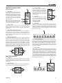
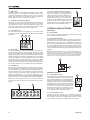
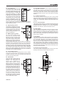
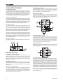
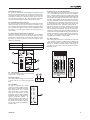
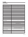
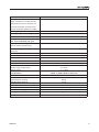
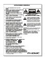
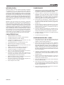
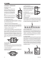
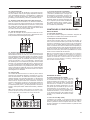
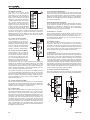
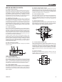
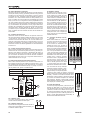
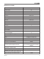
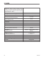
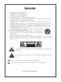

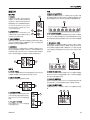
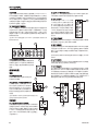
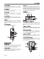
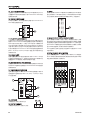
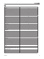
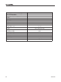
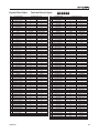
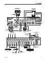
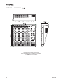
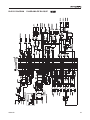


![CRP_26表面_003 [更新済み].ai](http://vs1.manualzilla.com/store/data/006591482_2-fb35ed91360138d8991f9e039d5833b2-150x150.png)