1
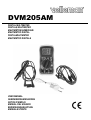
DVM205AM
DIGITAL MULTIMETER
DIGITALE MULTIMETER
MULTIMÈTRE NUMÉRIQUE
MULTÍMETRO DIGITAL
DIGITALMULTIMETER
MULTIMETRO DIGITALE
USER MANUAL
GEBRUIKERSHANDLEIDING
NOTICE D’EMPLOI
MANUAL DEL USUARIO
BEDIENUNGSANLEITUNG
MANUALE UTENTE
DVM205AM – DIGITAL MULTIMETER
1. Introduction
To all residents of the European Union
Important environmental information about this product
This symbol on the device or the package indicates that disposal of the device after its lifecycle could harm
the environment.
Do not dispose of the unit (or batteries) as unsorted municipal waste; it should be taken to a specialized
company for recycling.
This device should be returned to your distributor or to a local recycling service.
Respect the local environmental rules.
If in doubt, contact your local waste disposal authorities.
Thank you for buying the DVM205AM! Please read the manual thoroughly before bringing this device into service.
If the device was damaged in transit, you should contact your dealer and postpone installation of this device.
2. Safety Precautions
• Do not use your DVM205AM if the device itself or the test leads look damaged, or if you suspect that it is not
operating properly.
• Never ground yourself when making electrical measurements. Do not touch exposed metal pipes, outlets, fixtures,
etc. which might be at ground potential. Keep your body isolated from ground by wearing dry clothing and shoes
with rubber soles and using rubber mats or other approved insulating material.
• Turn off the power to the circuit under test before cutting, unsoldering or breaking it. Small amounts of current can
be dangerous.
• Be cautious when working above 60VDC or 30VAC as such voltages pose a shock hazard.
• When using the probes, make sure to keep your fingers behind the finger guards on the probes.
• Measuring voltage that exceeds the limits of the multimeter may damage your DVM205AM and expose the
operator to a shock hazard. Always respect the meter voltage and current limits as stated on the front of the
meter.
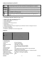
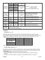
• Never apply voltage or current to the meter that exceeds the specified maximum:
Function
VDC or VAC
mA DC/AC
A DC/AC
Frequency, resistance, temperature,
capacitance, pulse width, dwell period,
duty cycle, diode test, continuity, RPM
Maximum Input
1000VDC; 750VAC
400mA DC/AC
10A DC/AC (30 seconds max every 15 minutes)
250VDC/AC
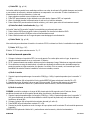
SAFETY SYMBOLS
This symbol adjacent to another symbol, terminal or operating device indicates that the operator
must refer to an explanation in this manual to avoid injury or damage to the meter.
This symbol indicates a potentially hazardous situation, which if not avoided, could result in death or
serious injury.
This symbol indicates a potentially hazardous situation which, if not avoided, may result in damage
to the device.
This symbol advises the user that the terminal(s) so marked must not be connected to a circuit point
at which the voltage with respect to ground exceeds (in this case) 500V AC/DC.
This symbol adjacent to one or more terminals identifies them as being associated with ranges that
may, in normal use, be subjected to particularly hazardous voltages. For maximum safety, the meter
and its test leads should not be handled when these terminals are energized.
DVM205AM
-3-
VELLEMAN
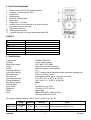
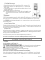
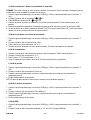
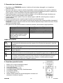
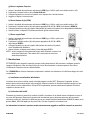
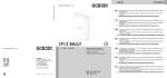
3. Front Panel Description
1.
2.
3.
4.
5.
6.
7.
8.
Display: large 4-digit LCD with symbol indications.
Frequency / duty cycle button (HZ/%)
Range button
Relative button
Data hold / backlight button
Mode button
Temperature °C/°F button
Selection switch: to turn the power on or off and select the
measurement function and range.
9. 10A (positive) input jack.
10. COM (negative) input jack.
11. + (positive) input jack for all other measurements than 10A.
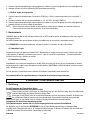
SYMBOLS
Continuity
Low Battery
Diode
Data Hold
Auto ranging
Alternating Current or Voltage
Direct Current or Voltage
BAT
DATA HOLD
AUTO
AC
DC
4. Specifications
Compliant with
Insulation
Overvoltage category
Display
Polarity
Overrange indication
Low-battery indication
Measurement rate
Auto power off
Operating temperature
Storage temperature
Max. altitude (indoors)
Pollution degree
Power source
Dimensions
Weight
Fuse
IEC1010-1 EN61010-1
Class2, double insulation
CATIII 600V, CATII 1000V
large 4-digit LCD with symbol signs
automatic, negative polarity indication
“OL”
“BAT” is displayed when the battery voltage drops below operating level
2 times per second, nominal
device powers off after approx. 15 minutes of inactivity
0°C to 50°C (32°F to 122°F) @ <70%RH
-20°C to 60°C (-4°F to 140°F) @ <80%RH
2000m
2
one 9V-battery (e.g. 6F22)
146 x 66.2 x 41.5 (H x W x D)
approx. 200g
400mA range: 250V / 500mA fast blow
10A range: 250V/10A fast blow
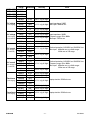
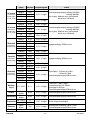
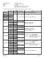
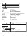
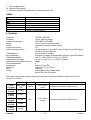
All accuracy indications below are valid for 18-28°C (65-83°F) @ <70% RH.
Accuracy
other
Range
Resolution
RPM 2-8CYL
500~10000
RPM
10RPM
±2.5% rdg ±4 digits Overload protection: 250Vac/dc rms
DWELL 2CYL
0~180.0°
0.1°
±2.5% rdg ±4 digits Overload protection: 250Vac/dc rms
DVM205AM
-4-
VELLEMAN
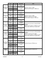
DWELL 4CYL
DWELL 5CYL
DWELL 6CYL
DWELL 8CYL
DC voltage
(auto-ranging)
AC voltage
(auto-ranging
except 400mV)
DC current
(auto-ranging for
µ A and mA)
AC current
(auto-ranging for
µ A and mA)
Resistance
(auto-ranging)
Capacitance
(auto-ranging)
DVM205AM
Range
0~90.0°
0~72.0°
0~60.0°
0~45.0°
400.0mV
4.000V
40.00V
400.0V
1000V
Resolution
Accuracy
0.1mV
1mV
10mV
100mV
1V
±0.5% rdg ±2 digits
400.0mV
4.000V
40.00V
400.0V
750V
400.0µ A
4000µ A
40.00mA
400.0mA
4A
10A
400.0µ A
4000µ A
40.00mA
400.0mA
4A
10A
400.0 Ω
4000 Ω
40.00kΩ
400.0kΩ
4.000MΩ
40.00MΩ
0.1mV
1mV
10mV
100mV
1V
0.1µ A
1µ A
10µ A
100µ A
1mA
10mA
0.1µ A
1µ A
10µ A
100µ A
1mA
10mA
0.1Ω
1Ω
10Ω
100 Ω
1kΩ
10kΩ
±1.5% rdg ±30 digits
±1.0% rdg ±3 digits Input impedance: 10MΩ
Frequency range: 50 to 400Hz
±1.5% rdg ±3 digits Max input: 750Vac rms
40.00nF
400.0nF
4.000µ F
40.00µ F
100.0µ F
10pF
0.1nF
1nF
10nF
0.1µ F
±5.0% rdg ±7 digits
±1.5% rdg ±2 digits
other
Input impedance: 10MΩ
Max. input: 1000Vdc rms
±1.8% rdg ±2 digits
±2.0% rdg ±4 digits
±1.0% rdg ±3 digits
±1.5% rdg ±3 digits Overload protection: 0.5A/250V and 10A/250V fuse
Max. input: 400mAdc rms on µ A/mA ranges
10Adc rms on 10A range
±2.5% rdg ±5 digits
±1.5% rdg ±5 digits
Overload protection: 0.5A/250V and 10A/250V fuse
±1.8% rdg ±5 digits Frequency range: 50 to 400Hz
Max. input: 400mAac rms on µ A/mA ranges
10Aac rms on 10A range
±3.0% rdg ±7 digits
±1.2% rdg ±4 digits
±1.0% rdg ±2 digits
±1.2% rdg ±2 digits
Input protection: 250Vdc/ac rms
±2.0% rdg ±3 digits
±3.0% rdg ±5 digits Input protection: 250Vdc/ac rms
±5.0% rdg ±5 digits
-5-
VELLEMAN
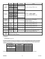
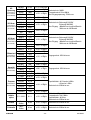
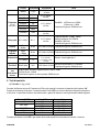
Frequency
(auto-ranging)
Duty cycle
Period
Pulse width
Temperature
Diode test
Audible
Continuity
9.999Hz
99.99Hz
999.9Hz
9.999kHz
99.99kHz
999.9kHz
9.999MHz
0.001Hz
0.01Hz
0.1Hz
1Hz
10Hz
100Hz
1kHz
Sensitivity: <0.5Vrms while ≤1MHz
>3Vrms while >1MHz
±1.2% rdg ±3 digits Overload protection: 250Vdc/ac rms
0.1%
Pulse width: >100µ s, 100ms
Frequency width: 5Hz-150kHz
±1.2% rdg ±2 digits
Sensitivity: <0.5Vrms
Overload protection: 250Vac/dc rms
0.1ms
±3% rdg ±10 digits Overload protection: 250Vac/dc rms
0.1ms
±3% rdg ±10 digits Overload protection: 250Vac/dc rms
0.1%~99.9%
2.0ms~
20.0ms
2.0ms
~10.0ms
±1.5% rdg ±5 digits
±1.5% rdg ±4 digits
±3% rdg ±3 digits
-20~+760°C
1°C
-4~+1400°F
1°F
(meter only ; probe
accuracy not included)
0.3mA
typical
1mV
±10% rdg ±5 digits
Sensor: K-type thermocouple
Open circuit voltage: 1.5Vdc typical
Overload protection: 250Vac/dc rms
Audible threshold: less than 50Ω
Test current: <0.3mA
Overload protection on all ranges: 250Vdc/ac rms
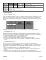
5. Control Buttons
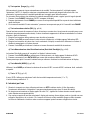
a) Hz / % Button (fig. p.2 #2)
This button allows you to choose between frequency and the duty cycle in a frequency range.
Press the HZ/% button to measure the frequency or the duty cycle while measuring voltage or current. For the
voltage/current requirements and frequency range, see the following table (for reference only):
Range (AC/DC)
4V
40V, 400V
1000V/750V
400mA
10A
Sensitivity
≥1.5V rms
≥6.5V rms
≥12V rms
≥420V rms
≥45mA rms
≥4A rms
Frequency width
5Hz~10kHz
5Hz~20kHz
5Hz~200kHz
50Hz~1kHz
5Hz~5kHz
5Hz~1kHz
Press the HZ/% button again to return to regular voltage or current measurement.
b) Range Button (fig. p.2 #3)
When the meter is switched on, it automatically goes into auto ranging ("AUTO" indication on the display). This
automatically selects the best range for the measurements being made and is generally the best mode for most
measurements. For measurements situations requiring a manually selected range, perform the following steps:
1. Press the RANGE button; the "AUTO" indication on the display will disappear.
2. Press the RANGE button repeatedly to skip through the available ranges until the required one is selected.
3. To return to auto ranging, press and hold the RANGE button for more than 2 seconds.
DVM205AM
-6-
VELLEMAN
c) Relative Button (fig. p.2 #4)
The relative measurement feature allows you to make measurements relative to a stored reference value. A
reference voltage, current etc. can be stored and measurements made in comparison to that value. The displayed
value is the difference between the reference value and the measured value.
1. Perform any measurement as described in the operating instructions.
2. Press the REL(ative) button to store the reading in the display and the REL indication will appear on the display.
3. The display will now indicate the difference between the stored value and the measured value.
4. Press the REL button to switch the relative function off and return to normal operation.
d) Data Hold / Backlight Button (fig. p.2 #5)
The data hold function allows the meter to "freeze" a measurement for later reference.
1. Press the DATA HOLD button to freeze the reading on the display. The HOLD indication will be displayed.
2. Press the DATA HOLD button again to return to normal operation.
Press the button for more than 2 seconds to switch the display backlight on or off.
e) Mode Button (fig. p.2 #6)
Use the Mode button to select AC/DC voltage, AC/DC current, resistance, diode, continuity or capacitance check.
f) °C/°F Button (fig. p.2 #7)
The °C/°F button is used to switch between °C and °F when measuring temperature.
The default temperature unit is °C.
6. Operating Instructions
1. Set the selection switch to the OFF position when the device is not being used. In order to prevent battery
leakage, the device automatically powers down when it has not been used for approx. 15 minutes.
2. If "OL" appears in the display during a measurement, the value exceeds the selected range. Select a higher range.
3. When a low voltage range is selected, the display may show a varying reading although the leads are not
connected to a device or circuit. This is normal and is caused by the high input sensitivity. The reading will
stabilize and give a proper measurement when connected to a circuit.
a) Voltage Measurements
1. Plug the black test lead in COM (fig. p.1 #10) and the red test lead in the + connector (#11).
2. Set the selection switch (#8) to the Vdc/ac position and press MODE (#6) to select AC or DC voltage.
3. Put the leads over the load to be measured and read the measured value from the LCD.
NOTE: Pressing the Hz/% button will cause the display to switch to frequency or duty cycle.
b) Current Measurements
CAUTION: Do not make current measurements on the 10A scale for longer than 30 seconds every 15 minutes.
Exceeding 30 seconds may cause damage to the meter and/or the test leads.
1. Plug the black test lead in the COM jack (#10) and the red test lead in the + jack (11) for max. 400mA
measurements, or in the 10A jack (#9) for max. 10A measurements.
2. Set the selection switch (#2) to the desired current measuring position (µ A, mA or A).
3. Press MODE (#6) to select AC or DC current.
4. Put the leads in series with the load under test and read the measured value from the LCD.
NOTE: Pressing the Hz/% button will cause the display to switch to frequency or duty cycle.
DVM205AM
-7-
VELLEMAN
c) Resistance / Diode / Continuity / Capacitance Measurements
CAUTION: To avoid electric shock, make sure all power of the circuit to be measured is off and all capacitors are
fully discharged when measuring resistance or capacitance.
1. Plug the black test lead in COM and the red test lead in the + connector (#11).
2. Set the selection switch (#8) to the Ω
CAP position.
3. Press the MODE button to select Ω,
or CAP.
4. Connect the test leads to the component or circuit to be measured and read the measured value from the LCD.
5. When testing continuity, a beeping sound shall be heard if the resistance is <30Ω.
6. When measuring the forward voltage across a diode, a normal diode will indicate 0.4V or 0.7V. The reverse
voltage will indicate "OL" (same as in open condition). A short-circuited diode will have a 0mV reading.
d) Frequency or Duty Cycle Measurements
1.
2.
3.
4.
Plug the black test lead in COM and the red test lead in the + connector (#11).
Set the selection switch (#8) to the Hz/%duty position.
Press the Hz/% button to select "Hz" or "%".
Connect the test leads to the circuit under test and read the frequency or the duty cycle on the display.
e) Temperature Measurements
1.
2.
3.
4.
Insert the type K thermocouple in the appropriate sockets: negative plug in COM, positive plug in +.
Set the selection switch (#2) to °C/°F.
Press the °C/°F button to select °C or °F.
Touch the target surface with the extremity of the probe and read the measured temperature from the LCD.
f) Period Measurements
1. Plug the black test lead in COM and the red test lead in the + connector (#11).
2. Set the selection switch (#2) to "Period ms".
3. Connect the black test lead to ground and the red test lead to the wire that connects to the component to be measured.
4. Read the measured value on the display.
NOTE: The applied time for most fuel injectors is displayed on the negative (-) slope.
g) Pulse Width Measurements
1.
2.
3.
4.
Plug the black test lead in COM and the red test lead in the + connector (#11).
Set the selection switch (#2) to "Pulse Width ms".
Connect the black test lead to ground and the red test lead to the wire that connects to the component to be measured.
Read the measured value on the display.
h) RPM Measurements
1.
2.
3.
4.
Plug the black test lead in COM and the red test lead in the + connector (#11).
Set the selection switch (#2) to the applicable position (2, 4, 5, 6 or 8CYL on the RPMx10 range).
Connect the black test lead to the negative pole of the car battery and connect the red test lead to a breaker point.
Crank the engine; the RPM (rotations per minute) will be displayed.
DVM205AM
-8-
VELLEMAN
i) Dwell Angle Measurements
1. Plug the black test lead in COM and the red test lead in the + connector (#11).
2. Set the selection switch (#2) to the applicable position (2, 4, 5, 6 or 8CYL on the
DWELL range).
3. Connect the black test lead to the negative pole of the car battery and connect the red
test lead to a breaker point.
4. Crank the engine; the dwell angle will be displayed.
NOTE: The dwell angle needs only be tested in cars with a traditional ignition system.
Cars with an electronic ignition system don't need to have the dwell angle
tested.
7. Maintenance
CAUTION: Before opening the case, set the selection switch to OFF and disconnect all test leads in order to avoid
electric shock hazard. Do not switch the device on before the battery/fuse compartment door is closed securely.
If your DVM205AM should not be operating properly, check the battery and fuses to make sure they are not faulty
and are properly inserted.
a) Install or Replace a Battery
The battery should be replaced when “BAT” appears on the display. Turn loose the screws at the back and open the
case. Remove the old battery (when replacing) and install a new one (1 x 9V-battery type 6F22 or equivalent) - mind
the polarity! Close the case and tighten the screws.
b) Replace a Fuse
The fuse rarely needs to be replaced; a blown fuse is usually the result of the operator's error. Turn loose the screws
at the back and open the case. Replace the old fuse (250V/0.5A fast blow for 400mA range; 250V/10A fast blow for
10A range), close the case and tighten the screws.
For warranty and service, please contact Velleman Components nv (www.velleman.eu).
The contents and specifications of this manual can be subject to change without prior notice
DVM205AM – DIGITALE MULTIMETER
1. Inleiding
Aan alle ingezetenen van de Europese Unie
Belangrijke milieu-informatie betreffende dit product
Dit symbool op het toestel of de verpakking geeft aan dat, als het na zijn levenscyclus wordt weggeworpen,
dit toestel schade kan toebrengen aan het milieu.
Gooi dit toestel (en eventuele batterijen) niet bij het gewone huishoudelijke afval; het moet bij een
gespecialiseerd bedrijf terechtkomen voor recyclage.
U moet dit toestel naar uw verdeler of naar een lokaal recyclagepunt brengen.
Respecteer de plaatselijke milieuwetgeving.
Hebt u vragen, contacteer dan de plaatselijke autoriteiten inzake verwijdering.
Dank u voor uw aankoop! Lees deze handleiding grondig voor u het toestel in gebruik neemt. Ga na of het toestel
niet werd beschadigd tijdens het transport. Zo ja, stel dan de installatie van het toestel uit en raadpleeg uw dealer.
DVM205AM
-9-
VELLEMAN
2. Veiligheidsvoorschriften
• Gebruik uw DVM205AM niet als het toestel zelf of de meetprobes er beschadigd uitzien, of als u vermoedt dat het
toestel niet naar behoren werkt.
• Zorg ervoor dat u niet geaard bent als u elektrische metingen uitvoert. Raak geen metalen leidingen en
voorwerpen aan die op aardepotentiaal kunnen zijn. Bescherm uw lichaam tegen aarding door droge kleren en
schoenen met rubber zolen te dragen en door rubber matjes te gebruiken (of een ander isolerend materiaal).
• Koppel altijd de stroomtoevoer los naar een schakeling die u wilt onderbreken of waar u componenten wilt aan
toevoegen of van weghalen. Kleine hoeveelheden stroom kunnen gevaarlijk zijn.
• Wees voorzichtig bij spanningen hoger dan 60Vdc en 30Vac; deze kunnen elektrische schokken veroorzaken.
• Als u de meetprobes gebruikt, houd deze dan vast achter de vingerbeschermingen.
• Spanningen meten die boven de limiet van de multimeter liggen, kan uw DVM205AM beschadigen en de
operateur elektrische schokken toebrengen. Respecteer altijd de spannings- en stroomlimieten zoals beschreven
op het toestel.
Gebruik de meter nooit met spanningen of stroom die de maximale waarden overschrijden:
Functie
Vdc of Vac
mA DC/AC
A DC/AC
Frequentie, weerstand, pulsbreedte, OPM,
werkingscyclus, temperatuur, continuïteit,
capaciteit, diodetest, onderbrekingsperiode
Maximum Input
1000Vdc; 750Vac
400mA DC/AC
10A DC/AC (max. 30 seconden elke 15 minuten)
250Vdc/ac
VEILIGHEIDSSYMBOLEN
Dit symbool naast een ander symbool, terminal of toestel geeft aan dat de gebruiker aandacht moet
schenken aan de instructies in de handleiding om kwetsuren en beschadiging aan de meter te
vermijden.
Geeft een gevaarlijke situatie weer en kan tot kwetsuren leiden of de dood tot gevolg hebben.
Geeft een gevaarlijke situatie weer en kan tot beschadiging van de meter leiden.
Vermijd aansluitingen aan een circuit met een spanning hoger dan 500 VAC of VDC.
Gevaarlijke spanning. Vermijd gebruik van de meter en meetsnoeren voor uw eigen veiligheid.
3. Beschrijving frontpaneel (zie figuur op blz. 2)
1. LCD-scherm: groot 4-digits LCD-scherm met symboolaanduidingen.
2. Schakelknop frequentie / werkingscyclus (Hz/%)
3. Bereikknop (Range)
4. Relatiefknop (REL)
5. Data Hold / achtergrondverlichtingsknop
6. Modeknop
7. Temperatuur °C/°F-knop
8. Selectieschakelaar: om het toestel in en uit te schakelen en meetfunctie en -bereik te bepalen.
9. 10A-aansluiting (positief)
10. COM (negatieve) aansluiting
11. + (positieve) aansluiting voor alle andere metingen dan 10A
DVM205AM
- 10 -
VELLEMAN
SYMBOLEN
Continuïteit
Zwakke batterij
Diode
Data Hold
Automatische bereikinstelling
Wisselstroom of –spanning
Gelijkstroom of –spanning
BAT
DATA HOLD
AUTO
AC
DC
4. Specificaties
Conform met
Isolatie
Overspanningcategorie
Scherm
Polariteit
Buitenbereik aanduiding
'Batterij laag'-aanduiding
Meetsnelheid
Automatische uitschakeling
Werktemperatuur
Opslagtemperatuur
Maximum hoogte (binnenshuis)
Vervuilingsgraad
Voedingsbron
Afmetingen
Gewicht
Zekering
IEC1010-1 EN61010-1
Klasse2, dubbele isolatie
CATIII 600V, CATII 1000V
groot 4-digits LCD met symboolaanduidingen
automatische aanduiding van negatieve polariteit
“OL”
“BAT” verschijnt op de display wanneer de batterij moet worden vervangen
2 metingen per seconde, nominaal
toestel schakelt zichzelf uit nadat het 15 seconden niet gebruikt is
0°C tot 50°C (32°F tot 122°F) @ <70%RH
-20°C tot 60°C (-4°F tot 140°F) @ <80%RH
2000m
2
één 9V-batterij (bv. 6F22)
146 x 66.2 x 41.5 (H x B x D)
ong. 200g
Bereik 400mA: 250V / 0.5A snelle doorslag
Bereik 10A: 250V / 10A snelle doorslag
Alle nauwkeurigheidsaanduidingen in de tabel hieronder gelden voor 18-28°C (65-83°F) @ <70% RV
RPM 2-8CYL
DWELL 2CYL
DWELL 4CYL
DWELL 5CYL
DWELL 6CYL
DWELL 8CYL
DC-spanning
(automatische
bereikbepaling)
AC-spanning
(automatische
bereikbepaling
behalve 400mV)
DVM205AM
Bereik
Resolutie
Nauwkeurigheid
500~10000
RPM
10RPM
±2.5% v/d uitlezing
Overbelastingsbeveiliging: 250Vac/dc rms
±4 digits
0.1°
±2.5% v/d uitlezing
Overbelastingsbeveiliging: 250Vac/dc rms
±4 digits
0~180.0°
0~90.0°
0~72.0°
0~60.0°
0~45.0°
400.0mV
4.000V
40.00V
400.0V
1000V
0.1mV
1mV
10Mv
100Mv
1V
±1.5% ±2 digits
400.0mV
0.1mV
±1.5% ±30 digits
4.000V
1mV
±1.0% ±3 digits
40.00V
400.0V
750V
10Mv
100Mv
1V
andere
±0.5% ±2 digits
Ingangsimpedantie: 10MΩ
Overbelastingsbeveiliging: 1000Vdc rms
±1.0% ±2 digits
±1.5% ±3 digits
Ingangsimpedantie: 10MΩ
Frequentiebereik: 50 tot 400Hz
Max. ingangsspanning: 750Vac rms
±2.0% ±4 digits
- 11 -
VELLEMAN
DC-stroom
(automatische
bereikbepaling
voor µ A en mA )
AC-stroom
(automatische
bereikbepaling
voor µ A en mA )
Weerstand
(automatische
bereikbepaling)
Capaciteit
(automatische
bereikbepaling)
Weerstand
(automatische
bereikbepaling)
Werkingscyclus
Periode
Pulsbreedte
Temperatuur
Diode test
Hoorbare
DVM205AM
Bereik
400.0µ A
4000µ A
40.00mA
400.0mA
4A
10A
400.0µ A
4000µ A
40.00mA
400.0mA
4A
10A
400.0 Ω
4000 Ω
40.00kΩ
400.0kΩ
4.000MΩ
40.00MΩ
Resolutie
0.1µ A
1µ A
10µ A
100µ A
1mA
10mA
0.1µ A
1µ A
10µ A
100µ A
1mA
10mA
0.1Ω
1Ω
10Ω
100Ω
1kΩ
10kΩ
Nauwkeurigheid
±1.0% ±3 digits
40.00nF
400.0nF
4.000µ F
40.00µ F
100.0µ F
9.999Hz
99.99Hz
999.9Hz
9.999kHz
99.99kHz
999.9kHz
9.999MHz
10pF
0.1nF
1nF
10nF
0.1µ F
0.001Hz
0.01Hz
0.1Hz
1Hz
10Hz
100Hz
1kHz
±5.0% ±7 digits
0.1%~99.9%
2.0ms~
20.0ms
2.0ms~
10.0ms
-20~+760°C
-4~+1400°F
typisch
0.3mA
±1.5% ±3 digits
andere
Overbelastingsbeveiliging: zekering 0.5A/250V
zekering 10A/250V
Max. ingang: 400mAdc rms in µ A/mA bereik
10Adc rms in 10A bereik
±2.5% ±5 digits
±1.0% ±3 digits
±1.5% ±3 digits
Overbelastingsbeveiliging: zekering 0.5A/250V
zekering 10A/250V
Max. ingang: 400mAdc rms in µ A/mA bereik
10Adc rms in 10A bereik
±2.5% ±5 digits
±1.2% ±4 digits
±1.0% ±2 digits
±1.2% ±2 digits
Ingangsbeveiliging: 250Vdc/ac rms
±2.0% ±3 digits
±3.0% ±5 digits
Ingangsbeveiliging: 250Vdc/ac rms
±5.0% ±5 digits
±1.5% ±5 digits
±1.2% ±3 digits
Gevoeligheid: <0.5Vrms bij ≤1MHz
>3Vrms bij >1MHz
Overbelastingsbeveiliging: 250Vdc/ac rms
±1.5% ±4 digits
0.1%
±1.5% ±4 digits
Pulsbreedte: >100µ s, 100ms
Frequentiebreedte: 5Hz-150kHz
Gevoeligheid: <0.5Vrms
Overbelastingsbeveiliging: 250Vac/dc rms
0.1ms
±1.5% ±4 digits
Overbelastingsbeveiliging: 250Vac/dc rms
0.1ms
±1.5% ±4 digits
Overbelastingsbeveiliging: 250Vac/dc rms
1°C
1°F
±1.5% ±4 digits
Sensor: K-type thermokoppel
1mV
±1.5% ±4 digits
Spanning open schakeling: typisch 1.5Vdc
Overbelastingsbeveiliging: 250Vac/dc rms
Hoorbare grens: minder dan 50Ω
- 12 -
VELLEMAN
Bereik
Resolutie
Nauwkeurigheid
andere
continuïteits- Teststroom: <0.3mA
test
Overbelastingsbeveiliging alle bereiken: 250Vdc/ac rms
5. Bedieningsknoppen
a) 'Hz / %' knop (fig. blz.1 #2)
Deze knop laat u toe te kiezen tussen frequentie of de werkingscyclus in een bepaald frequentiebereik.
Druk op de HZ/% knop om de frequentie of de werkingscyclus te meten terwijl u spanning of stroom meet. De
spanning/stroomvereisten en het frequentiebereik vindt u in de volgende tabel (enkel als voorbeeld):
Bereik (AC/DC)
4V
40V, 400V
1000V/750V
400mA
10A
Gevoeligheid
≥1.5V rms
≥6.5V rms
≥12V rms
≥420V rms
≥45mA rms
≥4A rms
Frequentiebereik
5Hz~10kHz
5Hz~20kHz
5Hz~200kHz
50Hz~1kHz
5Hz~5kHz
5Hz~1kHz
Druk nog eens op de HZ/% knop om terug te keren naar gewone spanning- of stroommeting.
b) 'Range' knop (fig. blz.1 #3)
Wanneer de meter aangezet wordt, gaat hij automatisch het bereik bepalen (aanduiding "AUTO" op het scherm). Zo
wordt automatisch het beste bereik geselecteerd voor uw metingen, en werkt ook het best voor de meeste metingen.
Voor metingen die een manuele bereikbepaling vereisen, volgt u de volgende stappen:
1. Druk op de RANGE knop ; de aanduiding "AUTO" op het scherm zal verdwijnen.
2. Druk herhaaldelijk op de RANGE knop om door de beschikbare bereiken te gaan tot het gewenste geselecteerd is.
3. Om terug te keren naar de automatische bepaling houdt u de RANGE knop langer dan 2 seconden ingedrukt.
c) 'Relative' knop (fig. blz.1 #4)
Met deze knop kunt u metingen doen waarbij de relatieve waarde weergegeven wordt: een referentiespanning, stroom etc. kan opgeslagen worden en nieuwe metingen worden weergegeven in verhouding tot die waarde. De
weergegeven waarde is het verschil tussen de opgeslagen waarde en de gemeten waarde.
1. Voer eender welke meting uit zoals weergegeven in de bedieningsinstructies.
2. Druk op de REL(atieve) knop om de gemeten waarde op te slaan ; de aanduiding REL verschijnt op het scherm.
3. Het scherm zal nu het verschil tussen de gemeten en de opgeslagen waarde weergeven.
4. Druk op de REL-knop om de relatieve functie uit te schakelen en terug te keren naar normale werking.
d) 'Data Hold' / achtergrondverlichting knop (fig. blz.1 #5)
Met de 'data hold' functie kunt u een meting "bevriezen" om later als referentie te gebruiken.
1. Druk op de DATA HOLD knop om de uitlezing op het scherm te bevriezen. De aanduiding HOLD zal verschijnen.
2. Druk nog eens op de DATA HOLD knop om terug te keren naar normale werking.
Hou de knop langer dan 2 seconden ingedrukt om de achtergrondverlichting aan of uit te zetten.
e) 'Mode' knop (fig. blz.1 #6)
Selecteer AC/DC spanning, AC/DC stroom, weerstand, diode, continuïteit of capaciteitcontrole met de Mode knop.
DVM205AM
- 13 -
VELLEMAN
f) '°C/°F' knop (fig. blz.1 #7)
De °C/°F knop wordt gebruikt om te schakelen tussen °C en °F bij temperatuurmetingen.
De standaard temperatuureenheid is °C.
6. Bedieningsinstructies
1. Zet de selectieschakelaar op de OFF-stand wanneer het toestel niet gebruikt wordt. Om de batterij te sparen en
lekken te voorkomen, schakelt het toestel zichzelf uit als het gedurende 15 minuten niet wordt gebruikt.
2. "OL" tijdens een meting wijst op een hogere waarde dan het geselecteerde bereik. Selecteer een hoger bereik.
3. Als een laag spanningsbereik geselecteerd is, kan de meter een schommelende uitlezing vertonen, hoewel de
meetprobes niet verbonden zijn met een toestel of schakeling. Dit is normaal en wordt veroorzaakt door de hoge
ingangsgevoeligheid. Tijdens de eigenlijke meting zal de meter een stabiele en correcte uitlezing geven.
a) Spanning meten
1. Steek de zwarte meetprobe in de COM-aansluiting (fig. blz.1 #10) en de rode probe in the "+"-aansluiting (#11).
2. Zet de selectieschakelaar (#8) op de Vdc/ac-stand en druk op MODE (#6) om AC of DC spanning te selecteren.
3. Plaats de probes over de te meten belasting en lees de gemeten waarde af van het LCD-scherm.
OPMERKING: door op de Hz/% knop te drukken schakelt u tussen frequentie en werkingscyclus.
b) Stroom meten
OPGELET: meet geen stroom op de 10A-schaal gedurende langer dan 30 seconden per kwartier. Langer meten dan
30 seconden kan de meter en/of de meetprobes beschadigen.
1. Steek de zwarte meetprobe in de COM-aansluiting (fig. blz.1 #10) en de rode probe in the "+"-aansluiting (#11)
voor metingen tot 400mA of in de 10A-aansluiting voor metingen tot 10A.
2. Zet de selectieschakelaar (#8) op de gewenste stroomstand (µ A, mA of A).
3. Druk op MODE (#6) om AC of DC stroom te selecteren.
4. Plaats de meetprobes in serie met de te meten belasting en lees de gemeten waarde af van het LCD-scherm.
OPMERKING: door op de Hz/% knop te drukken schakelt u tussen frequentie en werkingscyclus.
c) Weerstand / Diode / Continuïteit / Capaciteit meten
OPGELET: Zorg ervoor dat er geen stroom door de te meten schakeling vloeit en dat alle capaciteiten volledig
ontladen zijn als u weerstand of capaciteit gaat meten. Dit om elektrische schokken te vermijden.
1. Steek de zwarte meetprobe in de COM-aansluiting (fig. blz.1 #10) en de rode probe in the "+"-aansluiting (#11).
CAP-stand.
2. Zet de selectieschakelaar (#8) op de Ω
3. Druk op MODE om Ω,
, of CAP te selecteren.
4. Verbind de meetprobes met de te meten component of schakeling en lees de gemeten waarde af van de LCD.
5. Bij de continuïteitstest hoort u een piepgeluid wanneer de weerstand <30Ω is.
6. De doorlaatspanning over een diode zal voor een normale diode 0.4 of 0.7V bedragen ; de sperspanning zal als
"OL" uitgelezen worden (zoals in open toestand). Een kortgesloten diode heeft een 0mV-uitlezing.
d) Frequentie of werkingscyclus meten
1.
2.
3.
4.
Steek de zwarte meetprobe in de COM-aansluiting (fig. blz.1 #10) en de rode probe in the "+"-aansluiting (#11).
Zet de selectieschakelaar (#8) op de Hz/%duty-stand.
Druk op de Hz/%-knop om "Hz" of "%" te selecteren.
Verbind de meetprobes met de te meten schakeling en lees de waarde af van de LCD.
DVM205AM
- 14 -
VELLEMAN
e) Temperatuur meten
1.
2.
3.
4.
Steek het type K thermokoppel in de correcte aansluitingen: negatieve plug in COM, positieve plug in +.
Zet de selectieschakelaar (#8) op °C/°F.
Druk op de °C/°F-knop om °C of °F te selecteren.
Raak het doeloppervlak aan met het uiteinde van de probe en lees de gemeten waarde af van de LCD.
f) Periode meten
1. Steek de zwarte meetprobe in de COM-aansluiting (fig. blz.1 #10) en de rode probe in the "+"-aansluiting (#11).
2. Zet de selectieschakelaar (#8) op "Period ms".
3. Verbind de zwarte meetprobe met de aarding en de rode meetprobe met de kabel naar de te meten component.
4. Lees de gemeten waarde af van het scherm.
OPMERKING: De periode voor de meeste injectoren staat vermeld op de negatieve (-) hellingshoek.
g) Pulsbreedte meten
1.
2.
3.
4.
Steek de zwarte meetprobe in de COM-aansluiting (fig. blz.1 #10) en de rode probe in the "+"-aansluiting (#11).
Zet de selectieschakelaar (#8) op "Pulse Width ms".
Verbind de zwarte meetprobe met de aarding en de rode meetprobe met de kabel naar de te meten component.
Lees de gemeten waarde af van het scherm.
h) OPM meten
1.
2.
3.
4.
Steek de zwarte meetprobe in de COM-aansluiting (fig. blz.1 #10) en de rode probe in the "+"-aansluiting (#11).
Zet de selectieschakelaar (#8) op de toepasselijke positie (2, 4, 5, 6 of 8CYL op het bereik RPMx10).
Verbind de zwarte meetprobe met de negatieve pool van de batterij en de rode meetprobe met een onderbrekingspunt.
Start de motor ; het aantal OPM (omwentelingen per minuut) wordt weergegeven.
i) Onderbrekingshoek meten
1. Steek de zwarte meetprobe in de COM-aansluiting (fig. blz.1 #10) en de rode probe in the "+"-aansluiting (#11).
2. Zet de selectieschakelaar (#8) op de toepasselijke positie (2, 4, 5, 6 of 8CYL op het bereik "DWELL").
3. Verbind de zwarte meetprobe met de negatieve pool van de batterij en de rode meetprobe met een onderbrekingspunt.
4. Start de motor ; de onderbrekingshoek wordt weergegeven.
OPMERKING: de onderbrekingshoek dient enkel getest te worden in auto's met een traditionele ontsteking. Bij
wagens met een elektronisch ontstekingssysteem dient de onderbrekingshoek niet getest te worden.
7. Onderhoud
WAARSCHUWING: Zorg ervoor dat de selectieschakelaar op OFF staat en dat alle probes losgekoppeld zijn voor u
de behuizing opent; dit zal het risico op elektrische schokken wegnemen. Zet het toestel niet aan voor het deksel van
het batterij/zekeringcompartiment stevig dichtgemaakt is.
Als uw DVM205AM niet behoorlijk werkt, controleer dan eerst of de batterij en zekeringen nog goed zijn en correct
aangesloten zijn.
a) Batterij plaatsen of vervangen
Vervang de batterij wanneer de mededeling “BAT” op de LCD verschijnt. Maak de schroeven achteraan los en open
de behuizing. Verwijder de oude batterij (bij vervanging ), sluit een nieuwe batterij aan (1 x 9V-batterij, type 6F22 of
equivalent), sluit de behuizing en zet de schroeven terug vast.
DVM205AM
- 15 -
VELLEMAN
b) Zekering vervangen
De zekering dient slechts zelden vervangen te worden; gewoonlijk is een doorgebrande zekering het resultaat van
een fout van de gebruiker. Maak de schroeven achteraan los en open de behuizing. Vervang de oude zekering
(250V / 500mA voor het 400mA-bereik; 250V / 10A voor het 10A-bereik), sluit de behuizing en zet de schroeven
terug vast.
Voor garantie en service, neem contact op met Velleman Components nv (www.velleman.eu).
De inhoud van deze handleiding kan worden gewijzigd zonder voorafgaande kennisgeving.
DVM205AM – MULTIMÈTRE NUMÉRIQUE
1. Introduction
Aux résidents de l'Union européenne
Des informations environnementales importantes concernant ce produit
Ce symbole sur l'appareil ou l'emballage indique que l’élimination d’un appareil en fin de vie peut polluer
l'environnement.
Ne pas jeter un appareil électrique ou électronique (et des piles éventuelles) parmi les déchets municipaux
non sujets au tri sélectif ; une déchèterie traitera l’appareil en question.
Renvoyer les équipements usagés à votre fournisseur ou à un service de recyclage local.
Il convient de respecter la réglementation locale relative à la protection de l’environnement.
En cas de questions, contacter les autorités locales pour élimination.
Nous vous remercions de votre achat ! Lisez le présent manuel attentivement avant la mise en service de l'appareil.
Si l’appareil a été endommagé pendant le transport, remettez l'installation à plus tard et consultez votre revendeur.
2. Prescriptions de sécurité
• N'utilisez pas votre DVM205AM si l'appareil ou les probes sont endommagés, ou si l'appareil fonctionne mal.
• Ne vous mettez pas à la terre quand vous faites des mesures électriques. Ne touchez pas de conduites ou
d'objets métalliques qui peuvent être à potentiel de terre. Isolez votre corps de la terre en portant des vêtements
secs et des chaussures à semelles en caoutchouc et en utilisant un tapis en caoutchouc ou autre matière
isolatrice.
• Déconnectez l'alimentation du circuit sous test avant de l'interrompre ou d'en enlever ou y ajouter des
composants. Une petite quantité de courant peut être dangereux.
• Faites attention avec des tensions >60Vcc ou 30Vca afin d'éviter des électrochocs.
• Quand vous utilisez les probes, tenez-les derrière les protections de doigts.
• Mesurer des tensions supérieures aux limites du multimètre peut endommager votre appareil et peut exposer
l'opérateur aux électrochocs. Respectez toujours les limites de courant et de tension mentionnées à l’avant du
multimètre.
• Ne jamais utiliser le multimètre avec un courant ou une tension supérieurs aux valeurs maximales mentionnées:
Fonction
Vcc ou Vca
mA CC/CA
A CC/CA
Fréquence, résistance, période de
came, largeur d'impulsion, cycle de
fonctionnement, capacité, test du
diode, continuité, température, RPM
DVM205AM
Entrée maximale
1000Vcc ; 750Vca
400mA CC/CA
10A CC/CA (max. 30 sec. chaque 15 minutes)
250Vcc/ca
- 16 -
VELLEMAN
SYMBOLES CONCERNANT LA SÉCURITÉ
Ce symbole près d’un symbole, d’une borne ou appareil indique que l’utilisateur est contraint à lire
les instructions dans la notice afin d’éviter des blessures ou endommagements au multimètre.
Situation potentiellement dangereuse pouvant engendrer des blessures ou la mort si elle n’est pas
évitée.
Situation dangereuse pouvant engendrer des endommagements au multimètre si elle n’est pas
évitée..
A terminal marked with this symbol should not be connected to a circuit point of which the voltage
exceeds 500VAC or VDC above ground.
Ce symbole près d’une ou plusieurs bornes indique que celles-ci pourraient être sous tension. Pour
votre sécurité, reporter l’utilisation du multimètre et les fils de mesure lors de l’apparition de ce
symbole.
3. Description du panneau frontal (voir figure à la p.1)
1. Afficheur: LCD 4 digits avec indication de symboles.
2. Bouton fréquence/cycle de fonctionnement
3. Bouton "Range" (portée).
4. Bouton REL (relatif)
5. Bouton Data Hold / éclairage de l'écran
6. Bouton Mode.
7. Bouton température °C/°F
8. Sélecteur: pour activer et désactiver l’appareil et pour sélectionner la fonction et la plage de la mesure.
9. Connecteur 10A (positif)
10. Connecteur COM (négatif)
11. Connecteur + (positif) pour tout autre mesurage que 10A
SYMBOLES
BAT
DATA HOLD
AUTO
AC
DC
Continuité
Pile faible
Diode
Maintien de la lecture affichée
Instauration automatique de la gamme
Tension ou courant alternatifs
Tension ou courant directs
4. Spécifications
Conforme avec
Isolation
Catégorie de survoltage
Afficheur
Polarité
Indication hors plage
Indication pile faible
Echantillonnage
Débranchement automatique
Température de travail
Température de stockage
Altitude maximale (à l'intérieur)
Degré de pollution
DVM205AM
IEC1010-1 EN61010-1
Classe2, double isolation
CATIII 600V, CATII 1000V
LCD à 4 digits avec indication de symboles
indication automatique de polarité négative
“OL”
“BAT” apparaît quand la tension dépasse le niveau opérationnel
2 mesures par seconde, nominal
l'appareil s'éteint automatiquement après env. 15 minutes d'inactivité
0°C à 50°C (32°F à 122°F) @ <70%RH
-20°C à 60°C (-4°F à 140°F) @ <80%RH
2000m
2
- 17 -
VELLEMAN
Source d’alimentation
Dimensions
Poids
Fusible
1 pile 9V (p. ex. 6F22)
146 x 66.2 x 41.5 (H x La x P)
env. 200g
portée 400mA: 250V / 500mA à fusion rapide
portée 10A: 250V / 10A à fusion rapide
Toutes les indications de précision ci-dessous valent pour 18-28°C (65-83°F) à <70%HR
Plage
Résolution
Précision
DWELL 2CYL
500~10000
RPM
0~180.0°
DWELL 4CYL
0~90.0°
DWELL 5CYL
0~72.0°
DWELL 6CYL
0~60.0°
DWELL 8CYL
0~45.0°
400.0mV
4.000V
40.00V
400.0V
1000V
0.1mV
1mV
10mV
100mV
1V
±1.5% aff. ±2 digits
400.0mV
0.1mV
±1.5% aff.±30 digits
4.000V
1mV
40.00V
10mV
400.0V
750V
400µ A
4000µ A
40.00mA
400.0mA
4A
10A
100mV
1V
0.1µ A
1µ A
10µ A
100µ A
1mA
10mA
400µ A
4000µ A
40.00mA
400.0mA
4A
10A
400.0 Ω
4000 Ω
40.00kΩ
400.0kΩ
4.000MΩ
40.00MΩ
0.1µ A
1µ A
10µ A
100µ A
1mA
10mA
0.1Ω
1Ω
10Ω
100 Ω
1kΩ
10kΩ
RPM 2-8CYL
Tension CC
Tension CA
Courant CC
Courant CA
Résistance
DVM205AM
Autres
10RPM
±2.5% aff. ±4 digits Protection surcharge: 250Vca/cc rms
0.1°
±2.5% aff. ±4 digits Protection surcharge: 250Vca/cc rms
±0.5% aff. ±2 digits
Impédance d'entrée: 10MΩ
Entrée max.: 1000Vcc rms
±1.8% aff. ±2 digits
±1.0% aff.±3 digits Impédance d'entrée: 10MΩ
Plage de fréquence: 50 à 400Hz
±1.5% aff.±3 digits Entrée max.: 750Vca rms
±2.0% aff.±4 digits
±1.0% aff.±3 digits
±1.5% aff.±3 digits
Protection surcharge: fusible 0.5A/250V et
fusible 10A/250V
Entrée max.: 400mAcc dans les champs µ A/mA
10Acc dans le champ 10A
±2.5% aff.±5 digits
±1.5% aff.±5 digits
Protection surcharge: fusible 0.5A/250V et
10A/250V
±1.8% aff.±5 digits
Plage de fréquence: 50 à 400Hz
Entrée max.: 400mAcc dans les champs µ A/mA
10Acc dans le champ 10A
±3.0% aff.±7 digits
±1.2% aff.±4 digits
±1.0% aff.±2 digits
±1.2% aff.±2 digits
Protection surcharge: 250Vcc/ca rms
±2.0% aff.±3 digits
- 18 -
VELLEMAN
Capacité
Fréquence
Plage
40.00nF
400.0nF
4.000µ F
40.00µ F
100.0µ F
Résolution
Précision
Autres
10pF
±5.0% aff.±7 digits
0.1nF
±3.0% aff.±5 digits Protection surcharge: 250Vcc/ca rms
1nF
10nF
0.1µ F
±5.0% aff.±5 digits
9.999Hz
99.99Hz
999.9kHz
9.999kHz
99.99kHz
999.9kHz
9.999MHz
Cycle de
0.1%~99.9%
fonctionnement
0.001Hz
0.01Hz
0.1Hz
1Hz
10Hz
100Hz
1kHz
Sensibilité: <0.5Vrms à ≤1MHz
>3Vrms à >1MHz
±1.2% aff.±3 digits Protection surcharge: 250Vcc/ca rms
0.1%
Largeur d'impulsion: >100µ s, 100ms
Largeur de fréquence: 5Hz-150kHz
±1.2% aff.±2 digits
Sensibilité: <0.5Vrms
Protection surcharge: 250Vca/cc rms
±1.5% aff.±5 digits
±1.5% aff.±4 digits
2.0ms~
0.1ms
±3% aff.±10 digits
20.0ms
Largeur
2.0ms~
0.1ms
±3% aff.±10 digits
d'impulsion
10.0ms
-20~+760°C
1°C
Température
±3% aff.±3 digits
-4~+1400°F
1°F
typiquement
Test de diode
1mV
±10% aff.±5 digits
0.3mA
Seuil audible: <50 Ω.
Continuité
Courant de test: <0.3mA
audible
Protection surcharge: 250Vcc/ca
Période
Protection surcharge: 250Vca/cc rms
Protection surcharge: 250Vca/cc rms
Senseur: thermocouple type K
Tension circuit ouvert: typiquement 1.5Vcc
Protection surcharge: 250Vca/cc rms
5. Boutons
a) Bouton Hz/% (fig. p.1 #2)
Ce bouton vous permet de choisir entre la fréquence ou le cycle de fonctionnement dans une portée de fréquence.
Pressez le bouton Hz/% pour mesurer la fréquence ou le cycle de fonctionnement pendant que vous mesurez du
voltage ou du courant. Pour les exigences et gammes de fréquence voltage/courant, consultez la table suivante
(uniquement pour référence):
Portée (CA/CC)
Sensibilité
Gamme de fréquence
4V
≥1.5V rms
5Hz~10kHz
≥6.5V rms
5Hz~20kHz
40V, 400V
≥12V rms
5Hz~200kHz
1000V/750V
≥420V rms
50Hz~1kHz
400mA
≥45mA rms
5Hz~5kHz
10A
≥4A rms
5Hz~1kHz
Pressez le bouton Hz/% encore une fois pour retourner au mesurage normal de tension ou de courant.
DVM205AM
- 19 -
VELLEMAN
b) Bouton "Range" (portée) (fig. p.1 #3)
Quand le mètre est allumé, il détermine automatiquement la portée du mesurage (indicateur AUTO sur l'écran).
Dans la plupart des cas, c'est le meilleur mode pour des mesurages. Pour sélectionner la portée manuellement,
suivez les étapes suivantes:
1. Pressez le bouton RANGE ; l'indicateur AUTO disparaîtra de l'écran.
2. Pressez le bouton RANGE plusieurs fois pour parcourir les différentes portées et sélectionner la plus adéquate.
3. Pour retourner à la détermination automatique, pressez le bouton RANGE pendant plus de 2 secondes.
c) Bouton REL (fig. p.1 #4)
La fonction relative vous permet de faire des mesurages relatifs à une valeur de référence. Une tension ou un
courant de référence peut être sauvegardé et des mesurages peuvent être effectués en comparaison avec cette
valeur. La valeur affichée est la différence entre la valeur de référence et la valeur réelle.
1. Faites n'importe quel mesurage comme indiqué dans la notice.
2. Pressez REL pour sauvegarder la valeur indiquée comme valeur relative. "REL" sera affiché sur l'écran.
3. Dès maintenant, l'écran va afficher la différence entre la valeur réelle et la valeur de référence.
4. Pressez le bouton REL pour désactiver la fonction relative et pour donc retourner au fonctionnement normal.
d) Bouton Data Hold / éclairage de fond (fig. p.1 #5)
La fonction "data hold" vous permet de "geler" un mesurage pour référence plus tard.
1. Pressez le bouton HOLD pour geler la valeur sur l'écran. L'indication HOLD sera affichée.
2. Pressez le bouton HOLD encore une fois pour retourner au fonctionnement normal.
3. Pressez le bouton pendant plus de 2 secondes pour allumer/éteindre l'éclairage de fond.
e) Bouton Mode (fig. p.1 #6)
Utilisez ce bouton pour sélectionner tension ou courant CC/CA, résistance, diode, continuité ou capacité.
f) Bouton °C/°F (fig. p.1 #7)
Le bouton °C/°F sert à déterminer si l'affichage est en °C ou en °F.
6. Instructions d'opération
1. Mettez le sélecteur sur la position OFF quand l'appareil n'est pas utilisé. Afin d'éviter des piles vides ou coulantes,
l'appareil s'éteint automatiquement s'il n'est pas utilisé pendant 15 minutes.
2. Si "OL" apparaît pendant un mesurage, la valeur dépasse la portée. Sélectionnez une portée plus haute.
3. Si une portée de tension basse est sélectionnée, l'écran peut afficher une valeur instable bien que les probes ne
sont pas connectés ou ils ne sont pas connectés à un appareil ou un circuit. C'est normal et causé par la haute
sensibilité d'entrée. Pendant un mesurage, l'affichage sera stabile et juste.
a) Mesurer la tension
1. Insérez la probe noire dans le connecteur COM (fig. p.1 #10) et la probe rouge dans le connecteur "+" (#11).
2. Mettez le sélecteur (#8) à la position Vcc/ca et pressez MODE (#6) pour sélectionner la tension CA ou CC.
3. Connectez les probes à la charge à mesurer et lisez la valeur mesurée sur l'écran.
REMARQUE: en pressant le bouton Hz/%, vous alternez entre fréquence et cycle de fonctionnement.
DVM205AM
- 20 -
VELLEMAN
b) Mesurer le courant
ATTENTION: ne mesurez pas de courant dans le champ 10A pendant plus de 30 secondes par quart d'heure.
Mesurer pendant plus de 30 secondes peut endommager le mètre ou les probes.
1. Insérez la probe noire dans le connecteur COM (fig. p.1 #10) et la probe rouge dans le connecteur "+" (#11) pour
des mesurages jusqu'à 400mA ou dans le connecteur 10A pour des mesurages jusqu'à 10A.
2. Mettez le sélecteur (#8) à la position de courant désirée (µ A, mA ou A).
3. Pressez MODE (#6) pour sélectionner du courant CC ou CA.
4. Connectez les probes en série avec la charge à mesurer et lisez la valeur mesurée sur l'écran.
REMARQUE: en pressant le bouton Hz/%, vous alternez entre fréquence et cycle de fonctionnement.
c) Mesurer la résistance / une diode / la continuité / la capacité
ATTENTION: Pour éviter des électrochocs, veillez à ce qu'il ne coule pas de courant dans le circuit à mesurer et à ce
que les capacités sont complètement déchargées si vous allez mesurer de la résistance ou du capacité.
1. Insérez la probe noire dans le connecteur COM (fig. p.1 #10) et la probe rouge dans le connecteur "+" (#11).
2. Mettez le sélecteur (#8) à la position Ω
CAP.
3. Pressez MODE pour sélectionner Ω,
, ou CAP.
4. Connectez les probes avec le composant ou le circuit à mesurer et lisez la valeur mesurée sur l'écran.
5. Lors d'un test de continuité, vous entendez un signal sonore quand la résistance est <30Ω.
6. La tension directe d'une diode sera normalement 0.4 ou 0.7V ; la tension inverse sera affichée "OL" (comme en
condition ouverte). Une diode court-circuitée aura un affichage de 0mV.
d) Mesurer la fréquence ou le cycle de fonctionnement
1.
2.
3.
4.
Insérez la probe noire dans le connecteur COM (fig. p.1 #10) et la probe rouge dans le connecteur "+" (#11).
Mettez le sélecteur (#8) à la position Hz/%duty.
Pressez le bouton Hz/% pour sélectionner "Hz" ou "%".
Connectez les probes au circuit à mesurer et lisez la valeur mesurée sur l'écran.
e) Mesurer la température
1.
2.
3.
4.
Insérez le thermocouple type K dans les connecteurs correctes: fiche négative dans COM, fiche positive dans +.
Mettez le sélecteur (#8) à la position °C/°F.
Pressez le bouton °C/°F pour sélectionner °C ou °F.
Touchez la surface cible avec l'extrémité de la probe et lisez la valeur mesurée sur l'écran.
f) Mesurer la période
1. Insérez la probe noire dans le connecteur COM (fig. p.1 #10) et la probe rouge dans le connecteur "+" (#11).
2. Mettez le sélecteur (#8) à la position "Period ms".
3. Connectez la probe noire à la masse et la probe rouge au câble qui va au composant à mesurer.
4. Lisez la valeur mesurée sur l'écran.
REMARQUE : La période appliquée pour la plupart des injecteurs est mentionnée sur la dénivellation négative (-).
g) Mesurer la largeur d'impulsion
1.
2.
3.
4.
Insérez la probe noire dans le connecteur COM (fig. p.1 #10) et la probe rouge dans le connecteur "+" (#11).
Mettez le sélecteur (#8) à la position "Pulse Width ms".
Connectez la probe noire à la masse et la probe rouge au câble qui va au composant à mesurer.
Lisez la valeur mesurée sur l'écran.
DVM205AM
- 21 -
VELLEMAN
h) Mesurer les RPM
1.
2.
3.
4.
Insérez la probe noire dans le connecteur COM (fig. p.1 #10) et la probe rouge dans le connecteur "+" (#11).
Mettez le sélecteur (#8) à la position applicable (2, 4, 5, 6 of 8CYL de la portée RPMx10).
Connectez la probe noire au pôle négatif de la batterie et la probe rouge à une vis platinée.
Démarrez le moteur ; le nombre de RPM (révolutions par minute) est indiqué.
i) Mesurer l'angle d'interruption
1. Insérez la probe noire dans le connecteur COM (fig. p.1 #10) et la probe rouge dans le connecteur "+" (#11).
2. Mettez le sélecteur (#8) à la position applicable (2, 4, 5, 6 of 8CYL de la portée "DWELL").
3. Connectez la probe noire au pôle négatif de la batterie et la probe rouge à une vis platinée.
4. Démarrez le moteur ; l'angle d'interruption est indiqué.
REMARQUE: l'angle d'interruption ne doit être mesuré que dans des voitures avec un allumage traditionnel. Pour
des voitures à allumage électronique, il n'y a point besoin de le mesurer.
7. Remplacer la pile
ATTENTION: Avant d'ouvrir le boîtier, mettez le sélecteur (#2) sur OFF et enlevez les probes pour éviter des électrochocs.
N'allumez pas l'appareil avant que le couvercle des piles et fusibles soit fermé convenablement.
Si votre DVM205AM ne fonctionne pas comme il faut, vérifiez l'état et la connexion de la pile et des fusibles.
a) Remplacer la pile
Remplacez la pile quand le message “BAT” est affiché. Dévissez les vis à l'arrière et ouvrez le boîtier. Enlevez la pile
faible (si applicable) et insérez une nouvelle (1 x pile 9V, type 6F22 ou équivalent) - faites attention à la polarité!
Refermez le boîtier et serrez les vis.
b) Remplacer le fusible
Il est rare que les fusibles doivent être remplacés ; c'est généralement le résultat d'une faute de l'opérateur. Dévissez
les vis à l'arrière et ouvrez le boîtier. Remplacez le fusible défectueux (250V/500mA ou 250V/10A à fusion rapide),
refermez le boîtier et serrez les vis.
Pour la garantie et le service après vente, veuillez contacter SA Velleman Components (www.velleman.eu).
Le contenu et les spécifications du manuel peuvent être modifiées sans notification préalable.
DVM205AM – MULTÍMETRO DIGITAL
1. Introducción
A los ciudadanos de la Unión Europea
Importantes informaciones sobre el medio ambiente concerniente a este producto
Este símbolo en este aparato o el embalaje indica que, si tira las muestras inservibles, podrían dañar el
medio ambiente.
No tire este aparato (ni las pilas, si las hubiera) en la basura doméstica; debe ir a una empresa
especializada en reciclaje. Devuelva este aparato a su distribuidor o a la unidad de reciclaje local.
Respete las leyes locales en relación con el medio ambiente.
Si tiene dudas, contacte con las autoridades locales para residuos.
DVM205AM
- 22 -
VELLEMAN
¡Gracias por haber comprado el DVM205AM! Lea atentamente las instrucciones del manual antes de usarlo.
Verifique si el aparato ha sufrido algún daño en el transporte antes de la puesta en marcha. Si es el caso, no
conecte el aparato a la red y póngase en contacto con su distribuidor.
2. Instrucciones de seguridad
• No use el DVM205AM cuando las puntas de prueba o el aparato mismo están dañados o si el aparato funciona mal.
• Evite el contacto con el suelo al hacer mediciones. No toque objetos metálicos ni conductos que podrían estar
puestos a tierra. Mantenga su cuerpo aislado usando ropa seca, zapatos de goma o cualquier otro material de
aislamiento aprobado.
• Desconecte la alimentación del circuito a prueba antes de cortar, quitar o añadir componentes. Una pequeña
cantidad de corriente puede ser peligrosa puede ser peligrosa.
• Sea extremadamente cuidadoso al medir tensiones >60Vcc o 30Vca a fin de evitar descargas eléctricas.
• Si usa las puntas de prueba, mantenga los dedos detrás de las protecciones de dedos.
• Medir tensiones superiores a los límites del multímetro podría dañar su aparato y exponer al usuario a descargas
eléctricas. Respete siempre los límites de corriente como se indican en la parte frontal del aparato.
• Nunca utilice una tensión ni una corriente superior a los valores max.:
Función
Vcc o Vca
mA CC/CA
A CC/CA
Frecuencia, resistencia, temperatura,
capacidad, anchura de impulsos,
tiempo de parada, ciclo de
funcionamiento, capacidad, prueba de
diodo, continuidad, RPM
Entrada máx.
1000Vcc ; 750Vca
400mA CC/CA
10A CC/CA (máx. 30 seg. cada 15 minutos)
250Vcc/ca
SÍMBOLOS DE SEGURIDAD
¡Ojo! Consulte el manual del usuario para evitar lesiones o daños.
Este símbolo indica una situación peligrosa que podría causar lesiones o incluso la muerta.
Este símbolo indica una situación peligrosa que podría dañar el aparato.
No conecte una conexión marcada con este símbolo a un circuito cuya tensión sobrepasa 500VAC
o VDC sobre masa.
Este símbolo al lado de una o más conexiones indica una tensión peligrosa. Para una seguridad
máx., no utilice este aparato ni las puntas de prueba en cuanto aparezca este símbolo.
3. Descripción del panel frontal (véase figura en la p.1)
1. Display: pantalla LCD de 4 dígitos con indicación de símbolos.
2. Botón de frecuencia/ciclo de funcionamiento
3. Botón "Range" (rango).
4. Botón REL (relativo)
5. Botón Data Hold / retroiluminación
6. Botón "Mode".
7. Botón temperatura °C/°F
8. Selector: para activar y desactivar el aparato y para seleccionar la función y el rango de la medición.
9. Conector 10A (positivo)
10. Conector COM (negativo)
11. Conector (positivo) para cualquier medición distinta a 10ª
DVM205AM
- 23 -
VELLEMAN
SÍMBOLOS
Continuidad
Pila baja
Diodo
retención de lectura
Ajuste automático de la gama
Tensión o corriente alternativas
Tensión o corriente directas
BAT
DATA HOLD
AUTO
AC
DC
4. Especificaciones
Según
Aislamiento
Categoría de sobrecarga
Display
Polaridad
Indicador de sobre rango
Indicador de batería baja
Velocidad de medición
Auto apagado
Temperatura de funcionamiento
Temperatura de almacenamiento
Altura máx. (en el interior)
Grado de contaminación
Alimentación
Dimensiones
Peso
Fusible
IEC1010-1 EN61010-1
Clase2, aislamiento doble
CATIII 600V, CATII 1000V
LCD de 4 dígitos con indicación de símbolos
indicación automática de polaridad negativa
“OL”
se visualiza “BAT” en la pantalla si se debe reemplazar la pila
2 mediciones por segundo, nominal
el aparato se apaga automáticamente después de ± 15 minutos de inactividad
de 0°C a 50°C (de 32°F a 122°F) @ <70%RH
de -20°C a 60°C (de -4°F a 140°F) @ <80%RH
2000m
2
1 pila 9V (p.ej. 6F22)
146 x 66.2 x 41.5 (Al x An x P)
± 200g
alcance 400mA: 250V / 500mA fusible rápido
alcance 10A: 250V / 10A fusible rápido
Todas las siguientes indicaciones de precisión valen para 18-28°C (65-83°F) a <70%HR
Rango
Resolución
RPM 2-8CYL
500~10000
RPM
10RPM
±2.5% lectura ±4
Protección de sobrecarga: 250Vca/cc rms
dígitos
DWELL 2CYL
DWELL 4CYL
0~180.0°
0~90.0°
DWELL 5CYL
DWELL 6CYL
0~72.0°
0~60.0°
0.1°
±2.5% lectura ±4
Protección de sobrecarga: 250Vca/cc rms
dígitos
DWELL 8CYL
0~45.0°
Tensión CC
(selección de
rango automática)
DVM205AM
Precisión
Otros
400.0mV
0.1mV
±0.5% lectura ±2
dígitos
4.000V
40.00V
400.0V
1mV
10mV
100mV
±1.5% lectura ±2 Impedancia de entrada : 10MΩ
Entrada máx.: 1000Vcc rms
dígitos
1000V
1V
±1.8% lectura ±2
dígitos
- 24 -
VELLEMAN
Tensión CA
(selección de
rango automática
salvo 400mV)
Corriente CC
(selección de
rango automática
para µ A y mA)
Corriente CA
(selección de
rango automática
para µ A y mA)
Resistencia
(selección de
rango automática)
Capacidad
(selección de
rango automática)
DVM205AM
Rango
Resolución
Precisión
±1.5% lectura ±3
dígitos
Otros
400.0mV
0.1mV
4.000V
1mV
40.00V
400.0V
10mV
100mV
750V
1V
400µ A
0.1µ A
4000µ A
40.00mA
400.0mA
4A
10A
1µ A
10µ A
100µ A
1mA
10mA
Protección de sobrecarga: fusible 0.5A/250V y
±1.5% lectura ±3
fusible 10A/250V
dígitos
Entrada máx.: 400mAcc en los rangos µ A/mA
10Acc en el rango 10A
±2.5% lectura ±5
dígitos
400µ A
0.1µ A
±1.5% lectura ±5
dígitos
4000µ A
40.00mA
400.0mA
4A
10A
1µ A
10µ A
100µ A
1mA
10mA
400.0 Ω
0.1Ω
4000 Ω
1Ω
40.00kΩ
400.0kΩ
4.000MΩ
10Ω
100 Ω
1kΩ
±1.2% lectura ±2
dígitos
40.00MΩ
10kΩ
±2.0% lectura ±3
dígitos
40.00nF
10pF
±5.0% lectura ±7
dígitos
400.0nF
4.000µ F
40.00µ F
0.1nF
1nF
10nF
±3.0% lectura ±5
Protección de entrada: 250Vcc/ca rms
dígitos
100.0µ F
0.1µ F
±5.0% lectura ±5
dígitos
±1.0% lectura ±3
Impedancia de entrada : 10MΩ
dígitos
Rango de frecuencia: de 50 a 400Hz
±1.5% lectura ±3 Entrada máx.: 750Vca rms
dígitos
±2.0% lectura ±4
dígitos
±1.0% lectura ±3
dígitos
Protección de sobrecarga: fusible 0.5A/250V y
10A/250V
±1.8% lectura ±5
Rango
de
frecuencia:
de
50
a 400Hz
dígitos
Entrada máx.: 400mAcc en los rangos µ A/mA
10Acc en el rango 10A
±3.0% lectura ±7
dígitos
±1.2% lectura ±4
dígitos
±1.0% lectura ±2
dígitos
- 25 -
Protección de entrada: 250Vcc/ca rms
VELLEMAN
Frecuencia
(selección de
rango automática)
9.999Hz
99.99Hz
999.9kHz
9.999kHz
99.99kHz
999.9kHz
0.001Hz
0.01Hz
0.1Hz
1Hz
10Hz
100Hz
9.999MHz
1kHz
Ciclo de
0.1%~99.9%
funcionamiento
2.0ms~
20.0ms
Anchura de
2.0ms~
impulsos
10.0ms
-20~+760°C
Temperatura
-4~+1400°F
Prueba de
Típ.
diodos
0.3mA
Período
0.1%
0.1ms
0.1ms
±1.5% lectura ±5
dígitos
Sensibilidad: de <0.5Vrms a ≤1MHz
±1.2% lectura ±3
de >3Vrms a >1MHz
dígitos
Protección de sobrecarga: 250Vcc/ca rms
±1.5% lectura ±4
dígitos
Anchura de impulsos: >100µ s, 100ms
±1.2% lectura ±2 Anchura de frecuencia: 5Hz-150kHz
Sensibilidad: <0.5Vrms
dígitos
Protección de sobrecarga: 250Vca/cc rms
±3% lectura ±10
Protección de sobrecarga: 250Vca/cc rms
dígitos
±3% lectura ±10
Protección de sobrecarga: 250Vca/cc rms
dígitos
1°C
1°F
±3% lectura ±3
dígitos
1mV
±10% lectura ±5 Tensión en circuito abierto: típ.1.5Vcc
dígitos
Protección de sobrecarga: 250Vca/cc rms
Sensor: termopar tipo K
Umbral acústico: <50 Ω.
Continuidad
Corriente de prueba: <0.3mA
acústica
Protección de sobrecarga: 250Vcc/ca
5. Botones
a) Botón Hz/% (fig. p.1 #2)
Este botón le permite seleccionar entre la frecuencia o el ciclo de funcionamiento en un rango de frecuencia.
Pulse el botón Hz/% para medir la frecuencia o el ciclo de funcionamiento durante la medición de la tensión o de la
corriente. Para las exigencias tensión/corriente y rangos de frecuencia, consulte la siguiente lista (sólo como
referencia):
Rango (CA/CC)
Sensibilidad
Rango de frecuencia
4V
≥1.5V rms
5Hz~10kHz
≥6.5V rms
5Hz~20kHz
40V, 400V
≥12V rms
5Hz~200kHz
1000V/750V
≥420V rms
50Hz~1kHz
400mA
≥45mA rms
5Hz~5kHz
10A
≥4A rms
5Hz~1kHz
Vuelva a pulsar el botón Hz/% para volver a la medición normal de tensión o de corriente.
b) Botón "Range" (rango) (fig. p.1 #3)
Si el multímetro está activado, determina automáticamente el rango de medición (indicador AUTO en la pantalla).
En la mayoría de los casos, es el mejor modo para mediciones. Para seleccionar el rango manualmente, siga los
siguientes pasos:
1. Pulse el botón RANGE; el indicador AUTO desaparece de la pantalla.
2. Pulse el botón RANGE varias veces para recorrer por los diferentes rangos y seleccionar el rango más
adecuado.
3. Para volver a la selección automática del rango, pulse el botón RANGE durante más de 2 segundos.
DVM205AM
- 26 -
VELLEMAN
c) Botón REL (fig. p.1 #4)
La función relativa le permite hacer mediciones relativas a un valor de referencia. Es posible almacenar una tensión
o una corriente de referencia y efectuar mediciones en comparación con este valor. El valor visualizado es la
diferencia entre el valor de referencia y el valor real.
1. Haga cualquiera medición como se indica en el manual.
2. Pulse REL para almacenar el valor indicado como valor relativo. Aparece "REL" en la pantalla.
3. Ahora, la pantalla visualiza la diferencia entre el valor real y el valor de referencia.
4. Pulse el botón REL para desactivar la función relativa y, por lo tanto, para volver al funcionamiento normal.
d) Botón Data Hold / retroiluminación (fig. p.1 #5)
La función "data hold" le permite "congelar" una medición para referencia más tarde.
1. Pulse el botón HOLD para congelar el valor en la pantalla. Se visualiza la indicación HOLD.
2. Vuelva a pulsar el botón HOLD para volver al funcionamiento normal.
3. Pulse el botón durante más de 2 segundos para encender/apagar la retroiluminación.
e) Botón "Mode" (fig. p.1 #6)
Use este botón para seleccionar la tensión o la corriente CC/CA, resistencia, el diodo, la continuidad o la capacidad.
f) Botón °C/°F (fig. p.1 #7)
El botón °C/°F sirve para seleccionar entre °C y °F.
6. Instrucciones de operación
1. Coloque el selector en la posición OFF si no usa el aparato. Para evitar pilas vacías o fugas, el aparato se
desactiva automáticamente si no se usa durante 15 minutos.
2. Si "OL" aparece durante una medición, indica que el valor sobrepasa el rango. Seleccione un rango más elevado.
3. Si se selecciona un rango de tensión bajo, es posible que la pantalla visualice un valor inestable aunque las
puntas de prueba no están conectadas a un aparato o un circuito. Esto es normal y está causado por la alta
sensibilidad de entrada. Durante la medición, la lectura es estable y correcta.
a) Medir la tensión
1. Conecte la punta de prueba negra a la conexión COM (fig. p.1 #10) y la punta de prueba roja a la conexión "+"
(#11).
2. Coloque el selector (#8) en la posición Vcc/ca y pulse MODE (#6) para seleccionar la tensión CA o CC.
3. Conecte las puntas de prueba a la carga que Ud. desea probar. El valor medido aparece en la pantalla.
OBSERVACIÓN: pulsando el botón Hz/%, puede alternar entre frecuencia y ciclo de funcionamiento.
b) Medir la corriente
CUIDADO: no mida la corriente en el rango de 10A durante más de 30 segundos cada 15 minutos. Hacer
mediciones durante más de 30 segundos puede dañar el multímetro o las puntas de prueba.
1. Conecte la punta de prueba negra a la conexión COM (fig. p.1 #10) y la punta de prueba roja a la conexión "+"
(#11) para mediciones de corriente hasta 400mA o conecte la punta de prueba roja a la conexión 10A para
mediciones de hasta 10A.
2. Coloque el selector (#8) en la posición de corriente deseada (µ A, mA o A).
3. Pulse MODE (#6) para seleccionar corriente CC o CA.
4. Conecte las puntas de prueba en serie a la carga de la que quiere medir la corriente. El valor medido aparece en
la pantalla.
OBSERVACIÓN: pulsando el botón Hz/%, puede alternar entre frecuencia y ciclo de funcionamiento.
DVM205AM
- 27 -
VELLEMAN
c) Medir la resistencia / diodos / la continuidad / la capacidad
CUIDADO: Para evitar el riesgo de sufrir un choque eléctrico, desconecte el circuito a prueba y descargue todos los
condensadores antes de probar la resistencia en el circuito.
1. Conecte la punta de prueba negra a la conexión COM (fig. p.1 #10) y la punta de prueba roja a la conexión "+"
(#11).
2. Coloque el selector (#8) en la posición Ω
CAP.
3. Pulse MODE para seleccionar Ω,
, o CAP.
4. Conecte las puntas de prueba al componente o el circuito que desea probar. El valor medido aparece en la
pantalla.
5. Durante una prueba de continuidad, el zumbador incorporado emite una señal sonora si la resistencia <30Ω.
6. La tensión directa de un diodo normalmente indica 0.4 ó 0.7V; la tensión inversa indica "OL" (como en condición
abierta). Un diodo cortocircuitado tiene una lectura de 0mV.
d) Medir la frecuencia o el ciclo de funcionamiento
1. Conecte la punta de prueba negra a la conexión COM (fig. p.1 #10) y la punta de prueba roja a la conexión "+"
(#11).
2. Coloque el selector (#8) en la posición Hz/%duty.
3. Pulse el botón Hz/% para seleccionar "Hz" o "%".
4. Conecte las puntas de prueba al circuito que desea probar. El valor medido aparece en la pantalla.
e) Medir la temperatura
1.
2.
3.
4.
Conecte la sonda tipo K a las conexiones correctas: conector negativo a COM, conector positivo a +.
Coloque el selector (#8) en la posición °C/°F.
Pulse el botón °C/°F para seleccionar °C o °F.
Toque la superficie con el extremo de la sonda. El valor medido aparece en la pantalla.
f) Medir el período
1. Conecte la punta de prueba negra a la conexión COM (fig. p.1 #10) y la punta de prueba roja a la conexión "+"
(#11).
2. Coloque el selector (#8) en la posición "Period ms".
3. Conecte la punta de prueba negra a la masa y la punta de prueba roja al cable que está conectado al
componente a medir.
4. El valor medido aparece en la pantalla.
NOTA: El período aplicado para la mayoría de los inyectores en la pendiente negativa (-).
g) Medir la anchura de impulsos
1. Conecte la punta de prueba negra a la conexión COM (fig. p.1 #10) y la punta de prueba roja a la conexión "+"
(#11).
2. Coloque el selector (#8) en la posición "Pulse Width ms".
3. Conecte la punta de prueba negra a la masa y la punta de prueba roja al cable que está conectado al
componente a medir.
4. El valor medido aparece en la pantalla.
h) Medir RPM
1. Conecte la punta de prueba negra a la conexión COM (fig. p.1 #10) y la punta de prueba roja a la conexión "+"
(#11).
2. Coloque el selector (#8) en la posición aplicable (2, 4, 5, 6 ó 8CYL del rango RPMx10).
DVM205AM
- 28 -
VELLEMAN
3. Conecte la punta de prueba negra al polo negativo de la batería y la punta de prueba roja a un tornillo platinado.
4. Arranque el motor; se indica el número de RPM (revoluciones por minuto).
i) Medir el ángulo de interrupción
1. Conecte la punta de prueba negra a la conexión COM (fig. p.1 #10) y la punta de prueba roja a la conexión "+"
(#11).
2. Coloque el selector (#8) en la posición aplicable (2, 4, 5, 6 ó 8CYL del rango "DWELL").
3. Conecte la punta de prueba negra al polo negativo de la batería y la punta de prueba roja a un tornillo platinado.
4. Arranque el motor; se indica el ángulo de interrupción.
NOTA : Sólo es necesario medir el ángulo de interrupción en coches con un sistema de encendido tradicional.
Para coches con un encendido electrónico, no es necesario medirlo.
7. Mantenimiento
CUIDADO: Antes de abrir la caja, coloque el selector (#2) en OFF y quite las puntas de prueba para evitar todo riesgo de
descargas eléctricas.
No active el aparato salvo que la cubierta de pilas y de fusibles esté en su posición y firmemente cerrada.
Si el DVM205AM no funciona normalmente, verifique el estado y la conexión de la pila y los fusibles.
a) Reemplazar la pila
Reemplace la batería si aparece el símbolo “BAT”. Desatornille los tornillos de la parte trasera y abra la caja. Quite
la pila agotada (si aplicable) e introduzca una nueva (1 x pila 9V, tipo 6F22 o equivalente) - ¡Controle la polaridad!
Vuelva a cerrar la caja y atornille los tornillos.
b) Reemplazar el fusible
Normalmente, no es necesario reemplazar un fusible. Sólo se fundiría por un error de uso. Desatornille los tornillos
del panel posterior y abra la caja. Reemplace el fusible fundido (250V/500mA o 250V/10A rápido). Vuelva a cerrar la
caja y atornille los tornillos.
Para la garantía y el servicio posventa, contacte SA Velleman Components (www.velleman.eu).
Se pueden modificar las especificaciones y el contenido de este manual sin previo aviso.
DVM205AM – DIGITALMULTIMETER
1. Einführung
An alle Einwohner der Europäischen Union
Wichtige Umweltinformationen über dieses Produkt
Dieses Symbol auf dem Produkt oder der Verpackung zeigt an, dass die Entsorgung dieses Produktes nach
seinem Lebenszyklus der Umwelt Schaden zufügen kann.
Entsorgen Sie die Einheit (oder die verwendeten Batterien) nicht als unsortiertes Hausmüll; die Einheit oder
die verwendeten Batterien müssen von einer spezialisierten Firma zwecks Recycling entsorgt werden.
Diese Einheit muss an den Händler oder ein örtliches Recycling-Unternehmen retourniert werden.
Respektieren Sie die örtlichen Umweltvorschriften.
Falls Zweifel bestehen, wenden Sie sich für Entsorgungsrichtlinien an Ihre örtliche Behörde.
Wir bedanken uns für den Kauf des DVM205AM! Lesen Sie diese Bedienungsanleitung vor Inbetriebnahme
sorgfältig durch. Überprüfen Sie zuerst, ob Transportschäden vorliegen. In diesem Fall, nehmen Sie das Gerät nicht
in Betrieb und setzen Sie sich mit Ihrem Fachhändler in Verbindung.
DVM205AM
- 29 -
VELLEMAN
2. Sicherheitshinweise
• Verwenden Sie das DVM205AM nicht wenn das Gerät oder die Messleitungen Beschädigungen aufweisen, oder
wenn das Gerät nicht normal funktioniert.
• Erden Sie sich selber nie wenn Sie Spannungsmessungen durchführen. Berühren Sie keine Metallröhren, Steckdosen,
Vorrichtungen, usw., die mit der Erde verbunden sind. Tragen Sie während Messungen trockene Kleidung als Schutz :
Tragen Sie Schuhe mit Gummisohlen und/oder legen Sie eine Gummimatte oder genehmigtes Isolierungsmaterial
unter den Schuhen.
• Trennen Sie das Gerät immer vom Stromkreis, ehe Sie es ausschalten, unterbrechen oder ehe Sie Komponenten
hinzufügen oder entfernen. Auch kleine Strommengen können gefährlich sein.
• Seien Sie besonders vorsichtig beim Umgang mit Spannungen über 60Vdc und 30Vac ; diese könnten elektrische
Schläge verursachen.
• Halten Sie die Finger während Ihrer Messungen immer hinten dem Fingerschutz.
• Spannungen messen, die das Limit des Multimeters überschreiten, könnte das DVM205AM beschädigen und
einen elektrischen Schlag auslösen. Respektieren Sie immer die Spannungslimite, die auf der Vorderseite des
Meters stehen:
• Legen Sie nie einen höheren Strom oder eine höhere Spannung als angegeben wird an:
Funktion
Vdc oder Vac
mA DC/AC
A DC/AC
Frequenz, Widerstand, Pulsbreite, RPM,
Arbeitszyklus, Temperatur, Durchgang,
Kapazität, Diodentest, Schließwinkel
Max. Eingang
1000Vdc ; 750Vac
400mA DC/AC
10A DC/AC (max. 30 Sekunden jede 15 Minuten)
250Vdc/ac
SICHERHEITSSYMBOLE
WARNING
CAUTION
Dieses Symbol neben einem anderen Symbol, einem Anschluss oder Bedienelement
zeigt an, dass der Anwender die Richtlinien in dieser Bedienungsanleitung beachten soll,
um Personenschaden oder Beschädigung des Multimeters zu vermeiden.
Dieses Symbol weist auf eine gefährliche Situation, die zu ernsthaften Personenschaden
oder sogar zum Tode führen könnte wenn sie nicht vermieden wird, hin.
Dieses Symbol weist auf eine gefährliche Situation, die zu Schaden am Gerät führen
können, hin.
Ein Anschluss markiert mit diesem Symbol darf nicht an eine Schaltung, deren Spannung
500 VAC oder VDC über dem Erdpotenzial überschreitet, angeschlossen werden.
Dieses Symbol neben einem oder mehreren Anschlüssen zeigt an, dass diese sehr
gefährliche Spannungen haben können. Für maximale Sicherheit, verwenden Sie dieses
Gerät und die Messleitungen nicht wenn Sie dieses Symbol sehen.
3. Beschreibung Frontplatte (siehe Abb., S. 1)
1. LCD-Display: großes 4-stelliges LCD-Display mit Symbolanzeigen.
2. Taste Frequenz- / Arbeitszyklus (Hz/%)
3. Bereichstaste (Range)
4. Bezugswerttaste (REL)
5. Taste Data Hold / Hintergrundbeleuchtung
6. Mode-Taste
7. Temperatur °C/°F-Taste
8. Drehschalter: zum Ein- und Ausschalten des Gerätes und für die Auswahl von Bereich und Funktion.
9. 10A-Anschluss (positiv)
10. COM-Anschluss (negativ)
11. + (positiver) Anschluss für alle anderen Messungen als 10A
DVM205AM
- 30 -
VELLEMAN
SYMBOLE
Durchgang
BAT
"Lo-Bat"-Anzeige
Diode
DATA HOLD
AUTO
AC
DC
Data Hold
AutoRanging (automatische Bereichswahl)
Wechselstrom oder Wechselspannung
Gleichstrom oder Gleichspannung
4. Technische Daten
Gemäß
Isolierung
IEC1010-1 EN61010-1
Klasse2, doppelte Isolierung
CATIII 600V, CATII 1000V
großes 4-stelliges LCD-Display mit Symbolanzeigen
automatische Anzeige negativer Polarität
“OL”
“BAT” erscheint im Display wenn die Batterie gewechselt werden muss
2 Messungen pro Sekunde, nominell
das Gerät schaltet nach ca. 15 Min. automatisch ab
0°C bis 50°C (32°F bis 122°F) @ <70%RH
-20°C bis 60°C (-4°F bis 140°F) @ <80%RH
2000m
2
eine 9V-Batterie (z.B. 6F22)
146 x 66.2 x 41.5 (H x B x D)
± 200g
Bereich 400mA: 250V / 0.5A schnell
Bereich 10A: 250V / 10A schnell
Überspannungskategorie
Display
Polarität
Anzeige Bereichsüberschreitung
Lo-Bat-Anzeige
Messrate
Auto-Power-Off
Arbeitstemperatur
Lagertemperatur
Max. Höhe (im Haus)
Verschmutzungsgrad
Spannungsversorgung
Abmessungen
Gewicht
Sicherung
Alle Genauigkeitsanzeigen in folgender Tabelle gelten für 18-28°C (65-83°F) @ <70% RV
RPM 2-8CYL
DWELL 2CYL
DWELL 4CYL
DWELL 5CYL
DWELL 6CYL
DWELL 8CYL
DCSpannung
(automatische
Bereichswahl)
DVM205AM
Bereich
Auflösung
Genauigkeit
500~10000
RPM
10RPM
±2.5%
±4 Digits
Überlastschutz: 250Vac/dc rms
0.1°
±2.5% ±4 Digits
Überlastschutz: 250Vac/dc rms
0.1mV
1mV
10Mv
100Mv
1V
±0.5% ±2 Digits
0~180.0°
0~90.0°
0~72.0°
0~60.0°
0~45.0°
400.0mV
4.000V
40.00V
400.0V
1000V
±1.5% ±2 Digits
Andere
Überlastschutz: 10MΩ
Überlastschutz: 1000Vdc rms
±1.0% ±2 Digits
- 31 -
VELLEMAN
ACSpannung
(automatische
Bereichswahl
außer 400mV)
DC-Strom
(automatische
Bereichswahl für
µ A und mA )
AC-Strom
(automatische
Bereichswahl für
µ A und mA )
Widerstand
(automatische
Bereichswahl)
Kapazität
(automatische
Bereichswahl)
Frequenz
(automatische
Bereichswahl)
Arbeitszyklus
Periode
Pulsbreite
DVM205AM
400.0mV
0.1mV
±1.5% ±30 Digits
4.000V
40.00V
1mV
10Mv
±1.0% ±3 Digits
400.0V
750V
100Mv
1V
400.0µ A
4000µ A
40.00mA
400.0mA
4A
10A
0.1µ A
1µ A
10µ A
100µ A
1mA
10mA
400.0µ A
4000µ A
40.00mA
400.0mA
4A
10A
400.0 Ω
4000 Ω
40.00kΩ
400.0kΩ
4.000MΩ
40.00MΩ
40.00nF
400.0nF
4.000µ F
40.00µ F
100.0µ F
0.1µ A
1µ A
10µ A
100µ A
1mA
10mA
0.1Ω
1Ω
10Ω
100Ω
1kΩ
10kΩ
10pF
0.1nF
1nF
10nF
0.1µ F
9.999Hz
99.99Hz
999.9Hz
9.999kHz
99.99kHz
999.9kHz
9.999MHz
0.001Hz
0.01Hz
0.1Hz
1Hz
10Hz
100Hz
1kHz
0.1%~99.9%
2.0ms~
20.0ms
2.0ms~
10.0ms
±1.5% ±3 Digits
Überlastschutz: 10MΩ
Frequenzbereich: 50 tot 400Hz
Max. Eingangsspannung: 750Vac rms
±2.0% ±4 Digits
±1.0% ±3 Digits
±1.5% ±3 Digits
Überlastschutz: Sicherung 0.5A/250V
Sicherung 10A/250V
Max. Eingang: 400mAdc rms im µ A/mA-Bereich
10Adc rms im 10A-Bereich
±2.5% ±5 Digits
±1.0% ±3 Digits
±1.5% ±3 Digits
Überlastschutz: Sicherung 0.5A/250V
Sicherung 10A/250V
Max. Eingang: 400mAdc rms im µ A/mA-Bereich
10Adc rms im 10A-Bereich
±2.5% ±5 Digits
±1.2% ±4 Digits
±1.0% ±2 Digits
±1.2% ±2 Digits
Eingangsschutz: 250Vdc/ac rms
±2.0% ±3 Digits
±5.0% ±7 Digits
±3.0% ±5 Digits
Eingangsschutz: 250Vdc/ac rms
±5.0% ±5 Digits
±1.5% ±5 Digits
±1.2% ±3 Digits
Empfindlichkeit: <0.5Vrms bei ≤1MHz
>3Vrms bei >1MHz
Überlastschutz: 250Vdc/ac rms
±1.5% ±4 Digits
0.1%
±1.5% ±4 Digits
Pulsbreite: >100µ s, 100ms
Frequenzbreite: 5Hz-150kHz
Empfindlichkeit: <0.5Vrms
Überlastschutz: 250Vac/dc rms
0.1ms
±1.5% ±4 Digits
Überlastschutz: 250Vac/dc rms
0.1ms
±1.5% ±4 Digits
Überlastschutz: 250Vac/dc rms
- 32 -
VELLEMAN
-20~+760°C
1°C
±1.5% ±4 Digits
-4~+1400°F
1°F
typisch
Diodentest
1mV
±1.5% ±4 Digits
0.3mA
Akustische Akustische Grenze: weniger als 50Ω
Durchgangs- Teststrom: <0.3mA
prüfung
Überlastschutz alle Bereiche: 250Vdc/ac rms
Temperatur
Sensor: K-Typ-Fühler
Spannung für offene Schaltung : typisch 1.5Vdc
Überlastschutz: 250Vac/dc rms
5. Bedienungstasten
a) 'Hz / %' -Taste (Abb. S.1 #2)
Diese Taste erlaubt Ihnen zwischen Frequenz oder Arbeitszyklus in einem bestimmten Frequenzbereich zu wählen.
Drücken Sie die HZ/%-Taste um die Frequenz oder den Arbeitszyklus zu messen während Sie Spannung oder
Strom messen. Die Spannung/Stromerfordernisse und der Frequenzbereich finden Sie in folgender Tabelle (nur als
Beispiel):
Bereich (AC/DC)
4V
40V, 400V
1000V/750V
400mA
10A
Empfindlichkeit
≥1.5V rms
≥6.5V rms
≥12V rms
≥420V rms
≥45mA rms
≥4A rms
Frequenzbereich
5Hz~10kHz
5Hz~20kHz
5Hz~200kHz
50Hz~1kHz
5Hz~5kHz
5Hz~1kHz
Drücken Sie nochmals die HZ/%-Taste um zur normalen Spannung- oder Strommessung zurückzukehren.
b) 'Range'-Taste (Abb. S.1 #3)
Beim Einschalten bestimmt das Multimeter automatisch den Bereich (Anzeige "AUTO" im Bildschirm). So wird
automatisch der beste Bereich ausgewählt für Ihre Messungen, und funktioniert auch am besten. Für Messungen,
die eine manuelle Bereichswahl erfordern, folgen Sie folgenden Schritten:
1. Drücken Sie die RANGE-Taste ; die "AUTO"-Anzeige verschwindet.
2. Drücken Sie mehrmals die RANGE-Taste bis Sie den gewünschten Bereich erreicht haben.
3. Um zur automatischen Bereichswahl zurückzukehren, halten Sie die RANGE-Taste länger als 2 Sekunden
gedrückt.
c) 'Relative'-Taste (Abb. S.1 #4)
Mit dieser Taste können Sie Messungen durchführen, bei denen der relative Wert angezeigt wird: eine
Referenzspannung, -strom usw. kann gespeichert werden und neue Messungen werden im Verhältnis zu diesem
Wert angezeigt. Der angezeigte Wert ist die Differenz zwischen dem gespeicherten Wert und dem gemessenen
Wert.
1. Führen Sie irgendeine Messung durch wie gezeigt in der Bedienungsanleitung.
2. Drücken Sie die REL(ative)-Taste um den gemessenen Wert zu speichern ; die Anzeige REL erscheint im
Display.
3. Das Display zeigt nun den Unterscheid zwischen dem gemessenen und dem gespeicherten Wert.
4. Drücken Sie die REL-Taste um die relative Funktion auszuschalten und zum normalen Modus zurückzukehren.
DVM205AM
- 33 -
VELLEMAN
d) 'Data Hold'- / Hintergrundbeleuchtungstaste (Abb. S.1 #5)
Mit der 'Data Hold'-Funktion können Sie eine Messung "einfrieren" um später als Referenz zu verwenden.
1. Drücken Sie die ‘DATA HOLD’-Taste um die Anzeige im Display einzufrieren. Die Anzeige HOLD erscheint.
2. Drücken Sie die ‘DATA HOLD’-Taste nochmals, um zum normalen Betrieb zurückzukehren.
Halten Sie die Taste mehr als 2 Sekunden gedrückt um die Hintergrundbeleuchtung ein- oder auszuschalten.
e) 'Mode'-Taste (Abb. S.1 #6)
Wählen Sie AC/DC-Spannung, AC/DC-Strom, Widerstand, Diode, Durchgang oder Kapazität mit der Mode-Taste
aus.
f) '°C/°F'-Taste (Abb. S.1 #7)
Die °C/°F-Taste dient der Umschaltung zwischen °C und °F bei Temperaturmessungen.
Die Standard-Temperatureinheit ist °C.
6. Bedienungsanleitung
1. Stellen Sie den Wahlschalter in den OFF-Stand wenn das Gerät nicht verwendet wird. Um die Batterie zu
schonen, schaltet das Gerät automatisch ab wenn es während 15 Minuten nicht verwendet wird.
2. "OL" erscheint im Display wenn der gemessene Wert außen dem gewählten Bereich fällt. Wählen Sie einen
höheren Bereich.
3. Bei einem niedrigen Spannungsbereich, kann das Multimeter eine schwankende Anzeige aufweisen, obwohl die
Messleitungen nicht mit einem Gerät oder Schaltung verbunden sind. Dies ist normal und wird verursacht durch
die hohe Eingangsempfindlichkeit. Während der eigentlichen Messung wird das Multimeter eine stabile und
korrekte Anzeige geben.
a) Spannungsmessungen
1. Verbinden Sie die schwarze Messleitung mit der COM-Buchse (Abb. S.1 #10) und die rote mit der "+"-Buchse
(#11).
2. Stellen Sie den Wahlschalter (#8) auf Vdc/ac und drücken Sie MODE (#6) um AC- oder DC-Spannung
auszuwählen.
3. Stellen Sie die Messleitungen über die zu messenden Last. Der gemessene Wert erscheint im LCD.
BEMERKUNG: Drücken Sie die Hz/%-Taste, um zwischen Frequenz und Arbeitszyklus zu schalten.
b) Strommessungen
ACHTUNG: messen Sie keinen Strom an der 10A-Skale während länger als 30 Sekunden pro Viertelstunde. Länger
dauernde Messungen könnten das Multimeter und/oder die Messleitungen beschädigen.
1. Verbinden Sie die schwarze Messleitung mit der COM-Buchse (Abb. S.1 #10) und die rote mit der "+"-Buchse
(#11) für Messungen bis 400mA oder mit der 10A-Buchse für Messungen bis 10A.
2. Stellen Sie den Wahlschalter (#8) in den gewünschten Stromstand (µ A, mA of A).
3. Drücken Sie MODE (#6) um AC- oder DC-Strom auszuwählen.
4. Verbinden Sie die Messleitungen in Serie mit dem Messobjekt. Der gemessene Wert erscheint im LCD.
BEMERKUNG: Drücken Sie die Hz/%-Taste, um zwischen Frequenz und Arbeitszyklus zu schalten.
c) Widerstandsmessungen / Diodentest / Durchgangsprüfung / Kapazitätsmessungen
ACHTUNG: Sorgen Sie dafür, dass die Schaltung bei Widerstands- oder Kapazitätsmessungen spannungslos ist
und, dass alle Kondensatoren völlig entladen sind. So vermeiden Sie elektrische Schläge.
DVM205AM
- 34 -
VELLEMAN
1. Verbinden Sie die schwarze Messleitung mit der COM-Buchse (Abb. S.1 #10) und die rote mit der "+"-Buchse
(#11).
CAP-Stand.
2. Stellen Sie den Wahlschalter (#8) in den Ω
3. Drücken Sie MODE um Ω,
, oder CAP auszuwählen.
4. Verbinden Sie die Messleitungen mit der zu messenden Komponente oder Schaltung. Der gemessene Wert
erscheint im LCD.
5. Bei Durchgangsprüfung ertönt ein Warnsignal wenn der Widerstand <30Ω ist.
6. Die Vorwärtsspannung über eine Diode ist für eine normale Diode 0.4 oder 0.7V ; die Sperrspannung wird als
"OL" angezeigt (wie in offenem Zustand). Eine kurzgeschlossene Diode hat eine 0mV-Anzeige.
d) Frequenz oder Arbeitszyklus messen
1. Verbinden Sie die schwarze Messleitung mit der COM-Buchse (Abb. S.1 #10) und die rote mit der "+"-Buchse
(#11).
2. Stellen Sie den Wahlschalter (#8) in den Hz/%duty-Stand.
3. Drücken Sie die Hz/%-Taste um "Hz" oder "%" auszuwählen.
4. Verbinden Sie die Messleitungen mit der zu messenden Schaltung. Der gemessene Wert erscheint im LCD.
e) Temperatur messen
1.
2.
3.
4.
Stecken Sie den K-Typ-Fühler in den genauen Anschlüsse : negativ in COM, positiv in +.
Stellen Sie den Wahlschalter (#8) auf °C/°F.
Drücken Sie die °C/°F-Taste um °C oder °F auszuwählen.
Berühren Sie die Zieloberfläche mit der Spitze des Temperatursensors und lesen Sie die gemessenen Werte vom
LCD ab.
f) Periode messen
1. Verbinden Sie die schwarze Messleitung mit der COM-Buchse (Abb. S.1 #10) und die rote mit der "+"-Buchse
(#11).
2. Stellen Sie den Wahlschalter (#8) auf "Period ms".
3. Verbinden Sie die schwarze Messleitung mit der Erdung und die rote mit dem Kabel zum Messobjekt.
4. Der gemessene Wert erscheint im LCD.
HINWEIS: Die angewandte Zeit für die meisten Brennstoffdüsen werden auf der negativen (-) Neigung gezeigt.
g) Pulsbreite messen
1. Verbinden Sie die schwarze Messleitung mit der COM-Buchse (Abb. S.1 #10) und die rote mit der "+"-Buchse
(#11).
2. Stellen Sie den Wahlschalter (#8) auf "Pulse Width ms".
3. Verbinden Sie die schwarze Messleitung mit der Erdung und die rote mit dem Kabel zum Messobjekt.
4. Der gemessene Wert erscheint im LCD.
h) RPM messen
1. Verbinden Sie die schwarze Messleitung mit der COM-Buchse (Abb. S.1 #10) und die rote mit der "+"-Buchse
(#11).
2. Stellen Sie den Wahlschalter (#8) in die gewünschte Position (2, 4, 5, 6 oder 8CYL auf Bereich RPMx10).
3. Verbinden Sie die schwarze Messleitung mit dem negativen Pol der Batterie und die rote Messleitung mit einem
Unterbrecherkontakt.
4. Starten Sie den Motor ; die Zahl RPM (Umdrehungen pro Minute ) wird gezeigt.
DVM205AM
- 35 -
VELLEMAN
i) Schließwinkel messen
1. Verbinden Sie die schwarze Messleitung mit der COM-Buchse (Abb. S.1 #10) und die rote mit der "+"-Buchse
(#11).
2. Stellen Sie den Wahlschalter (#8) in die gewünschte Position (2, 4, 5, 6 oder 8CYL auf Bereich "DWELL").
3. Verbinden Sie die schwarze Messleitung mit dem negativen Pol der Batterie und die rote Messleitung mit einem
Unterbrecherkontakt.
4. Starten Sie den Motor; der Schließwinkel wird angezeigt.
BEMERKUNG: der Schließwinkel muss nur bei Autos mit einer traditionellen Zündung getestet werden. Bei Autos
mit einem elektronischen Zündsystem muss der Schließwinkel nicht getestet werden.
7. Wartung
WARNUNG: Trennen Sie das Messgerät vom Messkreis und schalten Sie es aus, ehe Sie das Gehäuse oder den
Batteriefachdeckel öffnen. So vermeiden Sie elektrische Schläge. Schalten Sie das Gerät niemals ein, ohne vorher
den Deckel (Batterien / Sicherung) geschlossen zu haben.
Wenn das DVM205AM nicht genau funktioniert, überprüfen Sie dann zuerst, ob die Batterie und die Sicherungen
noch gut sind und korrekt angeschlossen sind.
a) Batteriewechsel
Führen Sie einen Batteriewechsel durch wenn “BAT” im Display erscheint. Schrauben Sie die Schrauben auf der
Rückseite des Gehäuses los. Entfernen Sie die alte Batterie, legen Sie eine neue ein (1 x 9V-Batterie, Typ 6F22 oder
äquivalent), schließen Sie das Gehäuse und schrauben Sie die Schrauben wieder fest.
b) Sicherungswechsel
Sicherungen müssen normalerweise nur selten ersetzt werden und eine defekte Sicherung ist fast immer die Folge
eines menschlichen Fehlers. Sie die Schrauben auf der Rückseite des Gehäuses los und öffnen Sie das Gehäuse.
Ersetzen Sie die defekte Sicherung durch eine gleichen Typs (250V / 500mA für den 400mA-Bereich ; 250V / 10A für
den 10A-Bereich), schließen Sie das Gehäuse und schrauben Sie die Schrauben wieder fest.
Für Garantie und Service, wenden Sie sich an Velleman Components nv (www.velleman.eu).
Änderungen in Technik und Ausstattung ohne vorherige Ankündigung vorbehalten.
DVM205AM – MULTIMETRO DIGITALE
1. Introduzione
A tutti i residenti dell’Unione Europea
Importanti informazioni ambientali relative a questo prodotto
Questo simbolo riportato sul prodotto o sull’imballaggio, indica che è vietato smaltire il prodotto nell’ambiente
al termine del suo ciclo vitale in quanto può essere nocivo per l’ambiente stesso. Non smaltire il prodotto (o
le pile, se utilizzate) come rifiuto urbano indifferenziato; dovrebbe essere smaltito da un’impresa
specializzata nel riciclaggio.
Per informazioni più dettagliate circa il riciclaggio di questo prodotto, contattare l’ufficio comunale, il
servizio locale di smaltimento rifiuti oppure il negozio presso il quale è stato effettuato l’acquisto.
La ringraziamo per aver acquistato il DVM205AM! Assicurarsi che l’apparecchio non sia stato danneggiato durante il
trasporto; in tale evenienza, contattare il proprio fornitore. Si prega di leggere attentamente le informazioni contenute
nel presente manuale prima di utilizzare il dispositivo.
DVM205AM
- 36 -
VELLEMAN
2. Precauzioni per la sicurezza
• Non utilizzare mai il DVM205AM se questo o i relativi cavi di test risultano danneggiati o se si sospetta un
malfunzionamento.
• Non toccare tubi, infissi o strutture in metallo che potrebbero risultare a potenziale di terra quando si effettuano
delle misurazioni. Mantenere il proprio corpo isolato da terra indossando abbigliamento asciutto e calzature con
suola in gomma e servirsi eventualmente di specifici tappetini isolanti in gomma.
• Togliere alimentazione al circuito sotto test prima di eseguire su di esso operazioni di taglio, dissaldatura ecc.
Anche bassi valori di corrente potrebbero essere pericolosi!
• Prestare molta attenzione quando si lavora con tensioni superiori a 60V DC o 30V AC poiché vi è rischio di
scosse elettriche.
• Durante la misurazione tenere sempre le proprie dita dietro le protezioni dei puntali.
• La misurazione di tensioni con valori superiori a quelli massimi consentiti dallo strumento potrebbe danneggiare il
DVM205AM ed esporre l’operatore a rischio di scosse elettriche. Rispettare sempre il limite di tensione e corrente
specificati sul pannello frontale.
• Non applicare mai allo strumento tensioni o correnti che eccedono i valori massimi di seguito specificati:
Funzione
VDC o VAC
mA DC/AC
A DC/AC
Frequenza, resistenza, temperatura,
capacità, larghezza impulso, periodo,
angolo dwell, duty cycle, test diodi,
continuità, RPM.
Valore massimo d’ingresso
1000VDC; 750VAC
400mA DC/AC
10A DC/AC (30 secondi max ogni 15 minuti)
250VDC/AC
SIMBOLI DI SICUREZZA
Questo simbolo, adiacente ad un altro simbolo, terminale o apparecchio, indica che l'utente deve
fare riferimento alle indicazioni presenti nel manuale al fine di evitare lesioni personali o danni allo
strumento.
Questo simbolo indica una situazione potenzialmente pericolosa che, se non evitata, può provocare
decesso o lesioni gravi.
Questo simbolo indica una situazione potenzialmente pericolosa che, se non evitata, può provocare
danni al dispositivo.
Questo simbolo avvisa l'utente che il terminale/i così contrassegnato non deve essere collegato ad
un punto di un circuito in cui la tensione rispetto terra è superiore (in questo caso) a 500V AC / DC.
Questo simbolo posto accanto a uno o più terminali, associati a specifiche portate, indica che questi,
in condizioni normali di utilizzo, possono essere sottoposti a tensioni particolarmente pericolose.
Per garantire la massima sicurezza è bene che lo strumento e i relativi puntali non vengano
maneggiati quando questi sono sottoposti a tensione.
3. Descrizione pannello frontale
1.
2.
3.
4.
5.
6.
7.
8.
Display: LCD a 4 cifre con indicazione simboli.
Tasto Frequenza / Duty cycle (HZ/%)
Tasto Portata (Range)
Tasto Misurazione relativa (REL)
Tasto Memorizzazione dato (Hold) / Retroilluminazione
Tasto Modalità (MODE)
Tasto Temperatura (°C/°F)
Selettore rotativo: permette di accendere/spegnere lo strumento e di
selezionare la funzione e la portata.
DVM205AM
- 37 -
VELLEMAN
9. Boccola 10A (positivo).
10. Boccola COM (negativo).
11. Boccola + (positivo) utilizzata per tutte le misurazioni eccetto 10A.
SIMBOLI
Continuità
Batteria scarica
Diodo
Memorizzazione dato
Portata automatica
Corrente o Tensione alternata
Corrente o Tensione continua
BAT
DATA HOLD
AUTO
AC
DC
4. Specifiche
Conformità
Isolamento
Categoria sovratensione
Display
Polarità
Indicazione fuoriscala
Indicazione batteria scarica
Campionamento
Auto spegnimento
Temperatura operativa
Temperatura di stoccaggio
Altitudine massima (ambiente interno)
Grado d’inquinamento
Alimentazione
Dimensioni
Peso
Fusibile
IEC1010-1 EN61010-1
Class2, doppio isolamento
CATIII 600V, CATII 1000V
LCD a 4 cifre con indicazione simboli
automatica, indicazione polarità negativa
“OL”
sul display appare la scritta “BAT” quando il livello di carica della batteria
scende sotto il valore operativo
2 volte al secondo, nominale
lo strumento si spegne automaticamente dopo circa 15 minuti di inattività
da 0°C a + 50°C (da 32°F a 122°F) @ <70%RH
da -20°C a + 60°C (da -4°F a 140°F) @ <80%RH
2000m
2
batteria 9V (es. 6F22)
146 x 66,2 x 41,5 (H x W x D)
200g circa
portata 400mA: 250V / 500mA rapido
portata 10A: 250V / 10A rapido
Tutti i valori di accuratezza di seguito riportati sono riferiti ad una temperatura ambiente compresa tra 18 e 28°C
(65-83°F) @ <70% RH.
RPM
2-8 cilindri
DWELL
2 cilindri
DWELL
4 cilindri
DWELL
5 cilindri
DWELL
6 cilindri
DWELL
8 cilindri
DVM205AM
Portata
Risoluzione
Accuratezza
Varie
500~10000
RPM
10RPM
±2,5% lettura
±4 cifre
Protezione sovratensione: 250Vac/dc rms
0,1°
±2,5% lettura
±4 cifre
Protezione sovratensione: 250Vac/dc rms
0~180,0°
0~90,0°
0~72,0°
0~60,0°
0~45,0°
- 38 -
VELLEMAN
tensione DC
(portata
automatica)
Tensione AC
(portata
automatica,
eccetto 400mV)
Corrente DC
(portata
automatica
per µ A e mA)
Corrente AC
(portata
automatica
per µ A e mA)
Resistenza
(portata
automatica)
Capacità
(portata
automatica)
DVM205AM
Portata
Risoluzione
Accuratezza
±0,5% lettura
±2 cifre
400,0mV
0,1mV
4,000V
40,00V
400,0V
1mV
10mV
100mV
±1,5% lettura
±2 cifre
1000V
1V
±1,8% lettura
±2 cifre
400,0mV
0,1mV
4,000V
1mV
40,00V
400,0V
10mV
100mV
750V
1V
400,0µ A
0,1µ A
4000µ A
40,00mA
400,0mA
4A
10A
1µ A
10µ A
100µ A
1mA
10mA
400,0µ A
0,1µ A
4000µ A
40,00mA
400,0mA
4A
10A
1µ A
10µ A
100µ A
1mA
10mA
400,0 Ω
0,1Ω
4000 Ω
1Ω
40,00kΩ
400,0kΩ
4,000MΩ
10Ω
100 Ω
1kΩ
40,00MΩ
10kΩ
40,00nF
10pF
400,0nF
4,000µ F
40,00µ F
0,1nF
1nF
10nF
±1,5% lettura
±30 cifre
±1,0% lettura
±3 cifre
±1,5% lettura
±3 cifre
±2,0% lettura
±4 cifre
±1,0% lettura
±3 cifre
±1,5% lettura
±3 cifre
Varie
Impedenza d’ingresso: 10MΩ
Massima tensione d’ingresso: 1000Vdc rms
Impedenza d’ingresso: 10MΩ
Gamma di frequenza: da 50 a 400Hz
Massima tensione d’ingresso: 750Vac rms
Protezione da sovracorrente: fusibile 0,5A/250V e
10A/250V
Massima corrente d’ingresso: 400mAdc rms per le
portate µ A/mA, 10Adc rms per la portata 10A
±2,5% lettura
±5 cifre
±1,5% lettura
±5 cifre
±1,8% lettura
±5 cifre
±3,0% lettura
±7 cifre
Protezione da sovracorrente: fusibile 0,5A/250V e
10A/250V
Gamma di frequenza: da 50 a 400Hz
Massima corrente d’ingresso: 400mAac rms per le
portate µ A/mA, 10Aac rms per la portata 10A
±1,2% lettura
±4 cifre
±1,0% lettura
±2 cifre
±1,2% lettura
±2 cifre
±2,0% lettura
±3 cifre
±5,0% lettura
±7 cifre
Protezione d’ingresso: 250Vdc/ac rms
Protezione d’ingresso: 250Vdc/ac rms
±3,0% lettura
±5 cifre
- 39 -
VELLEMAN
Frequenza
(portata
automatica)
Portata
Risoluzione
100,0µ F
0,1µ F
9,999Hz
99,99Hz
999,9Hz
9,999kHz
99,99kHz
999,9kHz
0,001Hz
0,01Hz
0,1Hz
1Hz
10Hz
100Hz
9,999MHz
1kHz
Accuratezza
±5,0% lettura
±5 cifre
Varie
±1,5% lettura
±5 cifre
±1,2% lettura
±3 cifre
Sensibilità: <0,5Vrms con f ≤1MHz
>3Vrms con f >1MHz
Protezione d’ingresso: 250Vdc/ac rms
±1,5% lettura
±4 cifre
±1,2% lettura
±2 cifre
Larghezza impulso: >100µ s, 100ms
Gamma frequenza: 5Hz-150kHz
Sensibilità: <0,5Vrms
Protezione d’ingresso: 250Vac/dc rms
Duty cycle
0,1%~99,9%
0,1%
Periodo
2,0ms~
20,0ms
0,1ms
±3% lettura ±10 cifre Protezione d’ingresso: 250Vac/dc rms
Larghezza
impulso
2,0ms
~10,0ms
0,1ms
±3% lettura ±10 cifre Protezione d’ingresso: 250Vac/dc rms
-20~+760°C
1°C
-4~+1400°F
1°F
(solo strumento,
accuratezza sonda
esclusa)
0,3mA tipica
1mV
±10% lettura ±5 cifre
Temperatura
Test diodi
±3% lettura ±3 cifre
Sensore: termocoppia tipo K
Tensione circuito aperto: 1,5Vdc tipica
Protezione d’ingresso: 250Vac/dc rms
Continuità
Soglia minima intervento segnale acustico: minore di 50Ω
con
Corrente di test: <0,3mA
indicazione
Protezione d’ingresso su tutte le portate: 250Vdc/ac rms
sonora
5. Tasti di controllo
a) Tasto Hz / % (fig. p.2 #2)
Permette di effettuare misure di Frequenza o di Duty cycle quando lo strumento è impostato sulla funzione “Hz”.
Durante la misurazione di tensione o corrente premere il tasto HZ/% per avere indicazione relativa alla frequenza o
al duty cicle. Le specifiche relative a tensione/corrente e gamma di frequenza sono riportate nella tabella seguente:
Portata (AC/DC)
4V
40V, 400V
1000V/750V
400mA
10A
Sensibilità
≥1,5V rms
≥6,5V rms
≥12V rms
≥420V rms
≥45mA rms
≥4A rms
Gamma di frequenza
5Hz~10kHz
5Hz~20kHz
5Hz~200kHz
50Hz~1kHz
5Hz~5kHz
5Hz~1kHz
Premere nuovamente il tasto HZ/% per tornare alla normale modalità di misurazione di tensione o corrente.
DVM205AM
- 40 -
VELLEMAN
b) Tasto portata (Range) (fig. p.2 #3)
All’accensione lo strumento si pone automaticamente in modalità “Portata automatica” (sul display appare
l’indicazione "AUTO"). Il dispositivo seleziona automaticamente la portata più adeguata alla misura che si sta
effettuando. In genere questa è la modalità preferibile per la maggior parte delle misurazioni
Per situazioni di misurazione che richiedono la selezione manuale delle portate, seguire i passi di seguito riportati:
1. Premere il tasto RANGE; l’indicazione "AUTO" scompare dal display.
2. Premere ripetutamente il tasto RANGE per scorrere le varie portate disponibili fino a quando viene individuata
quella desiderata.
3. Per tornare alla modalità “Portata automatica”, premere e tenere premuto per più di 2 secondi il tasto RANGE.
c) Tasto misurazione relativa (REL) (fig. p.2 #4)
Questa funzione consente di comparare il valore di tensione o corrente che si sta misurando con quello preso come
riferimento (precedentemente memorizzato); il valore visualizzato rappresenta la differenza matematica tra il valore
misurato e quello di riferimento.
1. Eseguire la misurazione della grandezza come descritto nel manuale.
2. Premere il tasto REL per memorizzare il valore misurato (riferimento); sul display appare l’indicazione REL.
3. Eseguire la misurazione del valore che si vuole confrontare; il display ora mostrerà la differenza tra il valore di
riferimento memorizzato ed il valore misurato.
4. Premere il tasto REL per disattivare la funzione e tornare alla normale modalità di misurazione.
d) Tasto Memorizzazione dato/ Retroilluminazione (Data Hold / Backlight) (fig. p.2 #5)
La funzione Data Hold consente di “congelare” sul display il valore misurato.
1. Premere il tasto DATA HOLD per memorizzare il valore misurato; sul display appare l’indicazione HOLD.
2. Premere nuovamente il tasto DATA HOLD per tornare alla normale modalità di funzionamento.
Tenere premuto per più di 2 secondi il suddetto tasto per attivare o disattivare la retroilluminazione del display.
e) Tasto Modalità (MODE) (fig. p.2 #6)
Utilizzare il tasto MODE per effettuare la selezione di tensione AC/DC, corrente AC/DC, resistenza, diodi, continuità
o capacità.
f) Tasto °C/°F (fig. p.2 #7)
Il tasto °C/°F si utilizza per selezionare l’unità di misura della temperatura misurata (°C o °F).
L’unità di misura predefinita è °C.
6. Istruzioni per l’uso
1. Quando lo strumento non viene utilizzato posizionare su OFF il selettore rotativo. Al fine di prevenire
l’esaurimento della batteria, il dispositivo si spegne automaticamente dopo circa 15 minuti di inattività.
2. Se durante una misurazione sul display appare la scritta "OL", significa che il valore misurato eccede la portata
scelta. Selezionare una portata più alta.
3. Con una bassa portata di tensione selezionata il display può mostrare diverse letture anche se i puntali non sono
collegati al dispositivo o ad un circuito. Ciò è normale ed è dovuto all’alta sensibilità d’ingresso dello strumento.
La lettura si stabilizzerà e fornirà un valore corretto non appena i puntali verranno collegati ad un circuito.
DVM205AM
- 41 -
VELLEMAN
a) Misura di tensione
1. Inserire il terminale del puntale nero nella boccola COM (fig. p.2 #10) e quello rosso nella boccola + (#11).
2. Posizionare il selettore rotativo (#8) su Vdc/ac e premere il tasto MODE (#6) per selezionare tensione AC o DC.
3. Collegare i puntali al circuito da testare e leggere sul display LCD il valore di tensione misurato.
NOTA: la pressione del tasto Hz/% permette di visualizzare sul display il valore di frequenza o del duty cycle.
b) Misura di corrente
ATTENZIONE: con la portata 10A non effettuare misurazioni di corrente per più di 30 secondi ogni 15 minuti. Una
misurazione protratta per oltre 30 secondi potrebbe danneggiare lo strumento e/o i puntali.
1. Inserire il terminale del puntale nero nella boccola COM (fig. p.2 #10) e quello rosso nella boccola + (#11) per
misurazione di correnti fino a 400mA, o nella boccola 10A (#9) per correnti fino a max. 10A.
2. Posizionare il selettore rotativo (#8) su µA, mA o A.
3. Premere il tasto MODE (#6) per selezionare corrente AC o DC.
4. Collegare i puntali in serie al circuito da testare e leggere sul display LCD il valore di corrente misurato.
NOTA: la pressione del tasto Hz/% permette di visualizzare sul display il valore di frequenza o del duty cycle.
c) Misura di Resistenza / Diodi / Continuità / Capacità
ATTENZIONE: per evitare il rischio di scosse elettriche, durante la misurazione di resistenze e capacità, assicurarsi
che il circuito nel quale è montata il componente che si desidera testare sia privo di alimentazione e che tutti i
condensatori siano scarichi.
1. Inserire il terminale del puntale nero nella boccola COM (fig. p.2 #10) e quello rosso nella boccola + (#11).
CAP.
2. Posizionare il selettore rotativo (#8) su Ω
3. Premere il tasto MODE (#6) per selezionare Ω,
o CAP.
4. Collegare i puntali al componente o al circuito che si desidera testare e leggere sul display LCD il valore misurato.
5. Durante il test di continuità, lo strumento emette un segnale acustico se il valore di resistenza è <50Ω.
6. Quando si misura la tensione di polarizzazione diretta di un normale diodo, lo strumento indica un valore di 0,4 –
0,7V. Con polarizzazione inversa il display mostrerà la scritta "OL" (lo stesso avviene se la giunzione del diodo
risulta aperta) mentre fornirà una lettura pari a 0mV se il diodo risulta in corto circuito.
d) Misura di Frequenza o Duty Cycle
1.
2.
3.
4.
Inserire il terminale del puntale nero nella boccola COM (fig. p.2 #10) e quello rosso nella boccola + (#11).
Posizionare il selettore rotativo (#8) su Hz/%duty.
Premere il tasto Hz/% per selezionare "Hz" o "%".
Collegare i puntali al circuito sotto test e leggere sul display LCD il valore di Frequenza o di Duty cycle misurato.
e) Misura di Temperatura
1. Collegare il connettore della termocoppia tipo K all’apposito zoccolo adattatore, quindi inserire il terminale
negativo di quest’ultimo nella boccola COM e quello positivo nella boccola + dello strumento.
2. Posizionare il selettore rotativo (#8) su °C/°F.
3. Selezionare l’unità di misura desiderata (°C o °F) tramite il tasto °C/°F.
4. Porre l’estremità della sonda di temperatura a contatto del corpo del quale si desidera misurare la temperatura
quindi leggere sul display LCD il valore misurato.
f) Misura del Periodo
1.
2.
3.
4.
Inserire il terminale del puntale nero nella boccola COM (fig. p.2 #10) e quello rosso nella boccola + (#11).
Posizionare il selettore rotativo (#8) su Period ms.
Collegare il puntale nero a massa e il puntale rosso al punto che si desidera testare.
Leggere sul display il valore misurato.
DVM205AM
- 42 -
VELLEMAN
g) Misura Larghezza d’impulso
1.
2.
3.
4.
Inserire il terminale del puntale nero nella boccola COM (fig. p.2 #10) e quello rosso nella boccola + (#11).
Posizionare il selettore rotativo (#8) su Pulse Width ms.
Collegare il puntale nero a massa e il puntale rosso al punto che si desidera testare.
Leggere sul display il valore misurato.
h) Misura Numero di giri (RPM)
1.
2.
3.
4.
Inserire il terminale del puntale nero nella boccola COM (fig. p.2 #10) e quello rosso nella boccola + (#11).
Posizionare il selettore rotativo (#8) sulla portata appropriata (2, 4, 5, 6 o 8CYL) della funzione RPMx10 .
Collegare il puntale nero al polo negativo della batteria del veicolo ed il puntale rosso alle puntine del distributore.
Avviare il motore; sul display LCD verranno visualizzati i giri del motore al minuto.
i) Misura angolo Dwell
1. Inserire il terminale del puntale nero nella boccola COM (fig. p.2 #10) e quello rosso
nella boccola + (#11).
2. Posizionare il selettore rotativo (#8) sulla portata appropriata (2, 4, 5, 6 o 8CYL)
della funzione DWELL.
3. Collegare il puntale nero al polo negativo della batteria del veicolo ed il puntale
rosso alle puntine del distributore.
4. Avviare il motore; sul display verrà indicato il valore dell’angolo DWELL.
NOTE: occorre eseguire la misurazione dell’angolo dwell solamente sui motori con
accensione tradizionale. Tale verifica non è necessaria sui motori con
accensione elettronica.
7. Manutenzione
ATTENZIONE: prima di aprire il coperchio, presente sulla parte posteriore dello strumento, scollegare i puntali e
spegnere il dispositivo al fine di evitare il rischio di scosse. Non accendere lo strumento prima di aver chiuso
correttamente il coperchio del vano batteria/fusibile.
Se il DVM205AM non dovesse funzionare correttamente, verificare che la batteria ed i fusibili siano integri ed inseriti
correttamente.
a) Installazione o sostituzione della batteria
La batteria deve essere sostituita quando sul display appare la scritta “BAT”. Rimuovere il coperchio del vano
batteria (posto sulla parte posteriore dello strumento) svitando le relative viti. Sostituire la batteria vecchia con una
nuova avente le stesse caratteristiche (9V tipo 6F22 o equivalente); prestare attenzione alla polarità! Chiudere il
coperchio e riavvitare le viti.
b) Sostituzione dei fusibili
Raramente si presenta la necessità di sostituire i fusibili. La bruciatura di un fusibile avviene solitamente a causa di
un errore dell’operatore. Rimuovere il coperchio del vano batteria (posto sulla parte posteriore dello strumento)
svitando le relative viti. Sostituire il fusibile bruciato con uno avente identiche caratteristiche (250V/0,5A rapido, per la
portata 400mA; 250V/10A rapido per la portata 10A). Chiudere il coperchio e riavvitare le viti.
Le informazioni contenute in questo manuale possono essere soggette a modifiche senza alcun preavviso.
DVM205AM
- 43 -
VELLEMAN