1
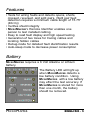
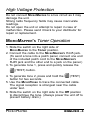
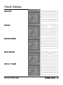
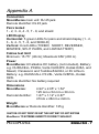
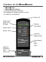
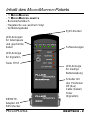
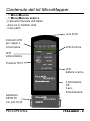
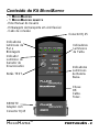
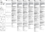
www.testequipmentdepot.com
MICROTOOLS
M ICRO M APPER
™
MICROMAPPER
TM
User Guide
Manuel Utilisateur
Benutzer Handbuch
Manuale per l'utente
Guía del Usuario
Manual do Utilizador
2947-4510-01 Rev. 01 11/01
© 2001 Fluke Networks, Inc. All rights reserved. Printed in USA.
All product names are trademarks of their respective companies.
99 Washington Street
Melrose, MA 02176
Phone 781-665-1400
Toll Free 1-800-517-8431
Visit us at www.TestEquipmentDepot.com
Test Equipment Depot
99 Washington Street
Melrose, MA 02176-6024
www.testequipmentdepot.com
800-517-8431
781-665-0780 FAX
Congratulations on your purchase of the MICROMAPPER network cable tester!
The MICROMAPPER is a hand-held cable tester that enables
network professionals to quickly and easily verify the integrity of Ethernet twisted pair cables. In one step, the
MICRO MAPPER will test twisted pair cabling for opens,
shorts, reversed, crossed, and split pairs. Simply slide
the switch to the Cable position, press the TEST button
and the MICROMAPPER will automatically scan for any existing faults in your cable. The specially designed remote
unit is provided for one-person testing of installed cabling. The tone generator function can be used with the
MICROPROBE cable tracer to trace cables and locate cables
hidden in ceilings, walls, floors, and bundles.
Contents
MicroMapper Kit Content ....................................................
Features .............................................................................
Battery ................................................................................
High Voltage Protection ......................................................
MicroMapper's Toner Operation .........................................
MicroMapper Tests .............................................................
Fault Status ........................................................................
Appendix A .........................................................................
MICROMAPPER
TM
2
3
3
4
4
5
6
7
ENGLISH - 1
MICROMAPPER Kit Content
- 1 MICROMAPPER
- 1 MICROMAPPER REMOTE
- This User Guide
- Soft vinyl carrying case
- Patch cord
RJ45 Jack
Pair and
Shield
Indicator
LEDs
Fault
LEDs
Toner LED
TEST Button
Low
Battery
LED
OffCableTonerswitch
REMOTE
Adapter
With
RJ45 Jack
MICROMAPPER
TM
ENGLISH - 2
Features
• Tests for wiring faults and detects opens, shorts,
crossed, reversed, and split pairs. (Split pair fault
detection requires a minimum cable length of 15.75"
(40cm))
• Verifies shield integrity
• MICROMAPPER'S Remote Identifier enables one
person to test installed cabling
• Easy to read fault display and high speed testing
• Generation of two tones for tracing cables and
locating hidden cables
• Debug-mode for detailed fault identification results
• Auto-sleep mode to decrease power consumption
Battery
MICROMAPPER requires a 6 Volt Alkaline or Lithium
battery.
The Battery LED will light up
when MICROMAPPER detects a
low battery condition. Using
MICROMAPPER with a low battery
may effect the test accuracy. If
MICROMAPPER is stored for more
than one month, the battery
should be removed.
MICROMAPPER
TM
ENGLISH - 3
High Voltage Protection
Do not connect MICROMAPPER to a live circuit as it may
damage the unit.
Strong radio frequency fields may cause inaccurate
readings.
Do not open the unit or attempt to repair in case of
malfunction. Please send it back to your distributor for
repair or replacement.
MICROMAPPER'S Toner Operation
1. Slide the switch on the right side of
MICROMAPPER to the Toner position.
2. Connect the cable to the MICROMAPPER's RJ45 jack.
(To send a tone into a patch panel, connect one end
of the included patch cord to the MICROMAPPER's
RJ45 jack and the other end to a jack on the panel.)
3. To generate tone 1, press and quickly release the
(TEST) button.
4. To generate tone 2, press and hold the
(TEST)
button for two seconds.
5. Use the MICROPROBE to trace the connected cable.
The signal reception is strongest near the cable
under test.
6. Slide the switch on the right side to the Off position
to discontinue the tone. (Always power the unit off to
prevent battery drain.)
MICROMAPPER
TM
ENGLISH - 4
MICROMAPPER Tests
1. Slide the switch on the right side to the Cable
position to turn MICROMAPPER on.
2. Connect one end of the cable to be tested to the
MICROMAPPER's RJ45 jack.
3. Connect the other end of the cable to the MICROMAPPER Remote's RJ45 jack.
(TEST) to view the results.
4. Press
5. The horizontal LEDs indicate the cable's integrity
status.
Green: Pair or Shield is good
Green flashing: Pair or Shield is faulty
No light: Pair is open or cable is not shielded
6. The vertical LEDs indicate the wiring faults and a low
battery status. Wiring faults are: SHORT, REVERSED, MISWIRE, SPLIT PAIRS.
7. To find out a fault on a specific pair, use
MICROMAPPER's diagnostic feature.
8. Press and hold
(TEST) for more than 2 seconds.
MICROMAPPER will scan each pair and the shield
pausing and flashing each green LED separately. If a
faulty pair is detected, the corresponding fault status
will blink in red.
Note: Push the Remote Terminator onto the MicroMapper until it snaps into position. This configuration
allows you to conveniently test patch cables.
MICROMAPPER
TM
ENGLISH - 5
Fault Status
SHORT
OPEN
REVERSED
MIS-WIRE
SPLIT PAIR
MICROMAPPER
TM
ENGLISH - 6
Appendix A
Connectors
MICROMAPPER main unit: RJ 45 jack
Remote Identifier: RJ 45 jack
Pairs tested
1 - 2, 3 - 6, 4 - 5, 7 - 8, and shield
LED Display
Horizontal: 5 green LEDs for pairs and shield display (1 - 2,
3 - 6, 4 - 5, 7 - 8, and SHIELD)
Vertical: 6 red LEDs (TONER, SHORT, REVERSED,
MISWIRE, SPLIT PAIRS, and LOW BATTERY)
Cables test limit
Minimum: 15.75" (40cm); Maximum:656' (200 m)
Power
MICROMAPPER: 6V alkaline DC battery (not included), Battery:
e.g. DURACELL PX28A, Varta VA034PX, Kodak K28A, and
Maxell, Panasonic and Toshiba #4LR44, or 6V Lithium
Battery: e.g. DURACALL PX 28L, Varta V28PXL, Kodak
K28L
Remote Identifier: No battery required
Dimensions
MICROMAPPER:
Remote Identifier:
4.92" x 2.05" x 1.54"
125 mm x 52 mm x 39 mm
1.87" x 1.12" x 0.87"
47mm x 28mm x 22mm
Weight
MICROMAPPER w/ Remote Identifier: 125 g
CAUTION: DO NOT DROP OR GET THE UNIT WET. DO NOT EXPOSE
MICROMAPPER TO EXTREME HUMIDITY OR DIRECT SUNLIGHT.
MICROMAPPER
TM
ENGLISH - 7
Merci d’avoir acheté le testeur de câbles réseau
MICROMAPPER network !
MICROMAPPER est un testeur de câbles portatif qui permet
aux spécialistes réseaux de vérifier, en un tournemain,
l’intégrité de câbles à paires torsadées Ethernet. Grâce
à cet appareil, une seule opération suffit pour détecter
des coupures, des courts-circuits, des paires croisées,
des paires partagées et des paires inversées sur des
câbles à paires torsadées. La procédure est enfantine :
orientez le commutateur en position Cable, appuyez sur
le bouton TEST et MICROMAPPER recherche automatiquement les anomalies éventuelles de votre câblage. L’unité
distante est conçue spécialement pour permettre à une
personne seule de tester les câbles installés. Utilisée de
concert avec le détecteur de câbles MICROPROBE, la fonction de génération de tonalités permet d’effectuer le suivi
des câbles et de localiser précisément les câbles cachés
dans des plafonds, parois, sols ou encore faisceaux.
Table des matières
Contenu du kit MicroMapper .............................................. 2
Fonctionnalités ................................................................... 3
Pile ..................................................................................... 3
Protection contre le risque de surtension ........................... 4
Utilisation du toner de MicroMapper ................................... 4
Tests MicroMapper ............................................................. 5
Etat des anomalies ............................................................. 7
Annexe A ............................................................................
8
TM
MICROMAPPER
FRANÇAIS - 1
Contenu du kit MICROMAPPER
- 1 MICROMAPPER
- 1 MICROMAPPER REMOTE
- Le présent Manuel de l’utilisateur
- Une mallette de transport souple en vinyle
- Un câble de raccordement
Fiche RJ-45
Voyants des
paires et du
blindage
Témoins
d’anomalies
Voyant Toner
Bouton TEST
Voyant de
batterie faible
Commutateur
Off
Cable
Toner
REMOTE
Adaptateur
avec
fiche RJ-45
MICROMAPPER
TM
FRANÇAIS - 2
Fonctionnalités
• Recherche d’anomalies de câblage et détection de coupures, de
courts-circuits, de paires croisées, de paires partagées et de paires
inversées. (La détection de paires partagées nécessite une
longueur de câble minimale de 40 cm).
• Vérification de l’intégrité du blindage.
• La fonction Remote Identifier de MICROMAPPER permet à une
personne seule de tester le câblage installé.
• Ecran d’anomalies d’une grande clarté et tests ultra-rapides.
• Génération des deux tonalités différentes pour le suivi des
câbles et la localisation de câbles cachés.
• Mode « débogage » pour des résultats détaillés sur l’identification
des anomalies.
• Mode veille automatique pour une consommation d’énergie
réduite.
Pile
MICROMAPPER nécessite l’emploi d’une pile alcaline ou
lithium de 6 volts. Le voyant de
batterie faible s’allume lorsque
MICROMAPPER détecte un état de
décharge avancée de la pile. Utiliser
MICROMAPPER avec une pile faible
risque d’affecter la précision des tests.
Si vous avez l’intention de ne pas
vous servir de MICROMAPPER pendant
plus d’un mois, retirez la pile de son
logement.
MICROMAPPER
TM
FRANÇAIS - 3
Protection contre le risque de surtension
Ne connectez pas MICROMAPPER à un circuit sous tension
car cela risquerait d’endommager l’unité.
La présence de champs haute fréquence peut nuire à la
précision des mesures. N’ouvrez pas l’unité ou
n’essayez pas de la réparer en cas de dysfonctionnement. En cas de problème, renvoyez l’unité à votre
distributeur qui effectuera la réparation ou procédera à
son remplacement.
Utilisation du toner de MICROMAPPER
1. Orientez le commutateur situé sur la face droite de
MICROMAPPER en position Toner.
2. Connectez le câble à la prise RJ-45 de MICROMAPPER.
(Pour envoyer une tonalité dans un tableau de
connexions, connectez une extrémité du câble de
raccordement fourni dans le kit à la prise RJ-45 de
MICROMAPPER et l’autre extrémité à une prise du
panneau de connexions.)
3. Pour générer une tonalité 1, appuyez sur le bouton
(TEST) et relâchez-le rapidement.
4. Pour générer une tonalité 2, appuyez sur le bouton
(TEST) et maintenez-le enfoncé pendant deux
secondes.
5. Utilisez MICROPROBE pour effectuer le suivi d’un câble
connecté. La réception du signal augmente à
MICROMAPPER
TM
FRANÇAIS - 4
mesure que l’on se rapproche du câble testé.
6. Orientez le commutateur situé sur la face droite de
MICROMAPPER en position Off pour interrompre la
tonalité. (Mettez toujours l’unité hors tension pour
empêcher l’épuisement de la pile.)
TESTS MICROMAPPER
1. Orientez le commutateur situé sur la face droite de
MICROMAPPER en position Cable pour mettre l’unité
sous tension.
2. Connectez une extrémité du câble à tester à la prise
RJ-45 de MICROMAPPER.
3. Connectez l’autre extrémité du câble à la prise RJ-45
de MICROMAPPER Remote.
(TEST) pour afficher les
4. Appuyez sur le bouton
résultats.
5. Les voyants disposés horizontalement indiquent le
degré d’intégrité du câble.
Vert : la paire ou le blindage est en bon état
Vert clignotant : la paire ou le blindage est défectueux
Aucun voyant allumé : la paire est coupée ou le
câble n’est pas blindé
6. Les voyants disposés verticalement signalent les
anomalies de câblage et un état de décharge
avancée de la pile. Voici les différents types
MICROMAPPER
TM
FRANÇAIS - 5
d’anomalies de câblage : SHORT (paire courtcircuitée), REVERSED (paire inversée), MISWIRE
(autre erreur de câblage), SPLIT PAIRS (paire
partagée).
7. Pour détecter une anomalie sur une paire spécifique,
utilisez la fonction de diagnostic de MICROMAPPER.
8. Appuyez sur le bouton
(TEST) et maintenez-le
enfoncé pendant plus de deux secondes.
MICROMAPPER va procéder à l’analyse systématique
des paires et du blindage, éteignant et allumant
chaque voyant vert individuellement. Si une paire
défectueuse est détectée, le voyant d’anomalie
correspondant se met à clignoter (rouge).
Remarque : enfoncez le Remote Terminator sur le
MicroMapper jusqu’à ce qu’il soit parfaitement en
place. Le cas échéant, vous entendrez un clic. Cette
configuration est très utile pour tester des câbles de
raccordement.
MICROMAPPER
TM
FRANÇAIS - 6
Etat des anomalies
SHORT
(court-circuit)
OPEN
(coupure)
REVERSED
(paire inversée)
MISWIRE
(erreur de
câblage)
SPLIT PAIR
(paire partagée)
MICROMAPPER
TM
FRANÇAIS - 7
Annexe A
Connecteurs
Unité principale MICROMAPPER : Prise RJ-45
Remote Identifier : Prise RJ-45
Paires testées
1 - 2, 3 - 6, 4 - 5, 7 - 8 et blindage
Affichage à DEL
Horizontalement : 5 voyants verts pour l’affichage des paires et du
blindage (1 - 2, 3 - 6, 4 - 5, 7 - 8 et BLINDAGE)
Verticalement : 6 voyants rouges (TONER, COUPURE, PAIRE
INVERSEE, ERREUR DE CÂBLAGE, PAIRE PARTAGEE et BATTERIE
FAIBLE)
Limite de test des câbles
Minimum : 40 cm ; Maximum : 200 m
Alimentation
MICROMAPPER : pile alcaline CC de 6 V (non fournie), Quelques
exemples de piles : DURACELL PX28A, Varta VAO34PX, Kodak K28A, et
Maxell, Panasonic et Toshiba #4LR44, ou pile lithium de 6 V, Quelques
exemples de piles : DURACALL PX 28L, Varta V28PXL, Kodak K28L
Remote Identifier : Aucune pile n’est requise
Dimensions
MICROMAPPER:
Remote Identifier:
125 mm x 52 mm x 39 mm
47mm x 28mm x 22mm
Poids
MICROMAPPER avec Remote Identifier: 125 g
ATTENTION : NE LAISSEZ PAS TOMBER L’UNITÉ ET EVITEZ DE RENVERSER
DU LIQUIDE SUR CELLE-CI. N’EXPOSEZ PAS MICROMAPPER À LA LUMIÈRE
DIRECTE DU SOLEIL OU À UNE HUMIDITÉ EXCESSIVE.
MICROMAPPER
TM
FRANÇAIS - 8
Herzlichen Glückwunsch zum Kauf des NetzwerkKabelprüfgeräts MICROMAPPER!
Der MICROMAPPER ist ein Handgerät zur Kabelprüfung, mit
dem Netzwerkspezialisten den Zustand von Twisted-PairKabeln in Ethernet-Netzwerken rasch und mühelos überprüfen können. In einem Arbeitsgang prüft der
MICROMAPPER Twisted-Pair-Verkabelungen auf Unterbrechungen, Kurzschlüsse, umgekehrte, überkreuzte und
vertauschte Paare. Setzen Sie den Schalter einfach auf
die Position “Cable” (Kabel), und drücken Sie die Taste
TEST. Dann sucht der MICROMAPPER automatisch nach
Fehlern, die u. U. in Ihrem Kabel vorhanden sind. Das
speziell entwickelte Remote-Gerät ist zum Prüfen der installierten Kabel durch eine Person gedacht. Die Signaltonfunktion kann mit dem Kabelverfolgungsgerät
MICROPROBE verwendet werden, um Kabel zu verfolgen
und um nach unter Putz in Decken, Wänden und Böden
oder in Bündeln verlegten Kabeln zu suchen.
Inhalt
Inhalt des MicroMapper-Pakets2
Funktionen ......................................................................... 3
Batterie ............................................................................... 3
Überspannungsschutz ........................................................ 4
MicroMapper-Signaltonbetrieb ........................................... 4
MicroMapper-Tests ............................................................. 5
Fehlerstatus ....................................................................... 7
Anhang A ...........................................................................
8
TM
MICROMAPPER
DEUTSCH - 1
Inhalt des MICROMAPPER-Pakets
- 1 MICROMAPPER
- 1 MICROMAPPER REMOTE
- Benutzerhandbuch
- Tragetasche aus weichem Vinyl
- Verbindungskabel
RJ45-Stecker
LED-Anzeigen
für Adernpaare
und geschirmte
Kabel
Fehleranzeigen
LED-Anzeige
für Signalton
Taste TEST
LED-Anzeige
für niedrige
Batterieladung
Schalter mit
den Positionen
Off (Aus)
Cable (Kabel)
Toner
(Signalton)
REMOTEAdapter mit
R45-Stecker
MICROMAPPER
TM
DEUTSCH - 2
Funktionen
• Prüft Kabel auf Verdrahtungsfehler und erkennt Unterbrechungen,
Kurzschlüsse, überkreuzte, umgekehrte und vertauschte Paare.
(Zur Erkennung von vertauschten Paaren muss das Kabel
mindestens 40 cm lang sein.)
• Prüft die Schirmung
• Mit dem MICROMAPPER-Remote-Prüfgerät kann die installierte
Verkabelung durch eine Person geprüft werden
• Leicht ablesbare Fehleranzeige und schnelle Prüfung
• Zwei verschiedene Töne zur Kabelverfolgung und zur Suchen
nach versteckten Kabeln
• Fehlerbehebungsmodus bei Einzelfehlererkennung
• Automatischer Ruhezustand zur Verringerung des Stromverbrauchs
Batterie
Für den MICROMAPPER ist eine 6 Volt-Alkali- oder
Lithiumbatterie erforderlich.
Die Batterieanzeige leuchtet auf,
wenn der MICROMAPPER feststellt,
dass die Batterieladung zu niedrig
ist. Eine niedrige Batterie-ladung
kann sich auf die Prüfgenauigkeit
des MICROMAPPER auswirken. Wenn
der MICROMAPPER länger als einen
Monat nicht in Gebrauch ist, sollte
die Batterie ausgetauscht werden.
MICROMAPPER
TM
DEUTSCH - 3
Überspannungsschutz
Schließen Sie den MICROMAPPER nicht an einen aktiven
Stromkreis an, da das Gerät dadurch beschädigt
werden könnte. Starke Funkfrequenzbereiche können
zu ungenauen Messergebnissen führen. Sie sollten das
Gerät weder öffnen noch versuchen, es bei Fehlfunktionen zu reparieren. Bitte senden Sie das Gerät zu
Reparatur- oder Austauschzwecken an Ihren Händler
zurück.
MICROMAPPER-Signaltonbetrieb
1. Schieben Sie den Schalter auf der rechten Seite des
MICROMAPPER auf die Position “Toner“.
2. Schließen Sie das Kabel am RJ45-Stecker des
MICROMAPPER an. (Zur Weiterleitung eines Tons in ein
Verbindungskabel schließen Sie das eine Ende des
mitgelieferten Verbindungskabel am RJ45-Stecker
des MICROMAPPER und das andere Ende an einem
Wandstecker an.)
3. Zum Erzeugen von Signalton 1 drücken Sie die
Taste
TEST, und lassen Sie diese dann rasch
los.
4. Zum Erzeugen von Signalton 2 halten Sie die Taste
TEST zwei Sekunden lang gedrückt.
5. Verfolgen Sie das angeschlossene Kabel mit dem
MICROMAPPER
TM
DEUTSCH - 4
MICROPROBE. Der Signaltonempfang ist in der Nähe
des jeweils zu prüfenden Kabels am stärksten.
6. Schieben Sie den Schalter auf der rechten Seite in
die Position Off (Aus), um den Signal-ton zu
unterbrechen. (Denken Sie daran, das Gerät
auszuschalten, damit sich die Batterie nicht zu
schnell entlädt.)
MICROMAPPER-Tests
1. Schieben Sie den Schalter auf der rechten Seite in
die Position Cable (Kabel), um den MICROMAPPER
einzuschalten.
2. Schließen Sie ein Ende des zu prüfenden Kabels am
RJ45-Stecker des MICROMAPPER an.
3. Schließen Sie das andere Kabelende am RJ45Stecker des MICROMAPPER-Remote-Geräts an.
TEST, um sich die
4. Drücken Sie die Taste
Messergebnisse anzeigen zu lassen.
5. Die horizontalen LED-Anzeigen zeigen den
Kabelzustand.
Grün: Pair-Kabel oder geschirmtes Kabel ist in
einwandfreiem Zustand
Grün (blinkend): Pair-Kabel oder geschirmtes Kabel
ist fehlerhaft
Kein Licht: Pair-Kabel ist unterbrochen, oder Kabel
ist nicht geschirmt
MICROMAPPER
TM
DEUTSCH - 5
6. Die vertikalen LED-Anzeigen zeigen
Verdrahtungsfehler und eine niedrige Batterieladung.
Mögliche Verdrahtungsfehler sind: SHORT
(Kurzschluss), REVERSED (Umgekehrt),
MISWIRE (falsche Verdrahtung), SPLIT PAIRS
(vertauschte Paare).
7. Zur Erkennung eines Fehlers an einem bestimmten
Paar verwenden Sie die Diagnosefunktion des
MICROMAPPER.
TEST länger als 2
8. Halten Sie die Taste
Sekunden gedrückt. Daraufhin tastet der
MICROMAPPER jedes Pair-Kabel und geschirmte Kabel
ab, wobei alle LED-Anzeigen jeweils einzeln blinken.
Bei Erkennung eines fehlerhaften Paars blinkt die
entsprechende Fehler-Statusanzeige rot.
Hinweis: Drücken Sie die Remote-Terminierung auf
den MicroMapper, bis sie hörbar einrastet. Mit dieser
Konfiguration können Sie Verbindungskabel
problemlos prüfen.
MICROMAPPER
TM
DEUTSCH - 6
Fehlerstatus
SHORT
(Kurzschluss)
OPEN
(Unterbrechung)
REVERSED
(Umgekehrt)
MIS-WIRE
(Falsche
Verdrahtung)
SPLIT PAIR
(Vertauschtes
Paar)
MICROMAPPER
TM
DEUTSCH - 7
Anhang A
Steckverbinder
MICROMAPPER-Hauptgerät: RJ 45-Stecker
Remote-Prüfgerät: RJ 45-Stecker
Geprüfte Paare
1 - 2, 3 - 6, 4 - 5, 7 - 8 und Schirmung
LED-Anzeige
Horizontal: 5 grüne LED-Anzeigen für Kabelpaare und geschirmte
Kabel (1 - 2, 3 - 6, 4 - 5, 7 - 8 und SHIELD (Schirmung))
Vertikal: 6 rote LED-Anzeigen (TONER (Signalton), SHORT
(Kurzschluss), REVERSED (Umgekehrt), MISWIRE (Falsche
Verdrahtung), SPLIT PAIRS (Vertauschte Paare) und LOW BATTERY
(Niedrige Batterieladung))
Max. und min. Kabelprüflänge
Min.: 40 cm; max. 200 m
Stromversorgung
MICROMAPPER: 6-V-Alkalibatterie, GS (nicht im Lieferumfang
enthalten), Batterie: z. B. DURACELL PX28A, Varta V34PX,
Kodak K28A und Maxell, Panasonic und Toshiba 4LR44,
oder 6V Lithiumbatterie: z.B. DURACALL PX 28L, Varta
V28PXL, Kodak K28L
Remote-Prüfgerät: Keine Batterie erforderlich
Abmessungen
MICROMAPPER:
Remote-Prüfgerät:
125 mm x 52 mm x 39 mm
47 mm x 28 mm x 22 mm
Gewicht
MICROMAPPER mit Remote-Prüfgerät: 125 g
ACHTUNG: LASSEN SIE DAS GERÄT NICHT FALLEN ODER FEUCHT WERDEN.
SETZEN SIE DEN MICROMAPPER NICHT EXTREMER FEUCHTIGKEIT ODER
DIREKTER SONNENEINSTRAHLUNG
AUS.
TM
MICROMAPPER
DEUTSCH - 8
Complimenti per aver acquistato il tester per cavi di
rete MICROMAPPER!
MICROMAPPER è un tester portatile per cavi che consente
ai professionisti delle reti di verificare in modo facile e
rapido l’integrità dei cavi twistati Ethernet. In un solo passaggio, MICROMAPPER controlla aperture, cortocircuiti, coppie invertite, incrociate e divise nei cablaggi twistati. È
sufficiente orientare il commutatore in posizione Cable,
premere il pulsante TEST e MICROMAPPER esegue automaticamente la scansione dei cavi, ricercando errori e
guasti. L’unità remota, grazie allo speciale design, permette a una sola persona di effettuare il collaudo dei
cablaggi installati. La funzione di generazione segnali
acustici è utilizzabile con il dispositivo di tracciatura cavi
MICROPROBE per individuare e seguire il percorso dei cavi
nascosti in soffitti, pareti e pavimenti e raccolti in fasci.
Indice
Contenuto del kit MicroMapper ............................................ 2
Funzionalità ......................................................................... 3
Batteria ................................................................................ 3
Protezione da alta tensione ................................................. 4
Funzionamento del sintonizzatore di MicroMapper .............. 4
Test di MicroMapper ............................................................ 5
Stati di errore ....................................................................... 7
Appendice A ........................................................................ 8
TM
MICROMAPPER
ITALIANO - 1
Contenuto del kit MicroMapper
- 1 MICROMAPPER
- 1 MICROMAPPER REMOTE
- Il presente Manuale dell’utente
- Astuccio in morbido vinile
- Cavo patch
Jack RJ45
Indicatori LED
per coppie e
schermatura
LED di errore
LED
sintonizzatore
Pulsante TEST
LED
batteria scarica
Commutatore
OffCavoSintonizzatoreAdattatore
REMOTO
con jack RJ45
MICROMAPPER
TM
ITALIANO - 2
Funzionalità
• Verifica i difetti dei cavi in grado di rilevare aperture, cortocircuiti,
coppie incrociate, invertite e divise (per individuare le coppie
divise è necessaria una lunghezza minima di cavo di 40 cm
(15,75”)).
• Verifica l’integrità della schermatura
• L’identificatore remoto di MICROMAPPER consente a una sola
persona di collaudare il cablaggio installato
• Display guasti di facile lettura e test molto rapidi
• Emissione di segnali acustici per la tracciatura di cavi e
l’individuazione di cavi nascosti
• Modalità debug per risultati dettagliati di identificazione guasti
• Modalità standby automatica per ridurre il consumo
Batteria
MICROMAPPER funziona con una batteria alcalina o litio da
6 Volt.
Il LED batteria si accende quando
MICROMAPPER rileva la condizione di
batteria scarica. L’uso di MICROMAPPER
con la batteria scarica può pregiudicare la precisione dei test. Se
MICROMAPPER non viene utilizzato per
oltre un mese occorre rimuovere la
batteria.
MICROMAPPER
TM
ITALIANO - 3
Protezione da alta tensione
Non collegare MICROMAPPER a un circuito attivo; l’unità
potrebbe venire danneggiata. Campi di radiofrequenze
ad elevata intensità possono provocare errori di lettura.
Non aprire l’unità o tentare di ripararla in caso di guasti.
Inviare l’unità al locale distributore per la riparazione o
la sostituzione.
Funzionamento del sintonizzatore di
MICROMAPPER
1. Portare il commutatore sul lato destro di
MICROMAPPER nella posizione Toner.
2. Collegare il cavo al jack RJ45 di MICROMAPPER (per
inviare un segnale acustico al pannello patch,
collegare un’estremità del cavo patch in dotazione al
jack RJ45 di MICROMAPPER e l’altra estremità a un
jack del pannello).
3. Per generare un segnale acustico 1, premere e
rilasciare rapidamente il pulsante
TEST.
4. Per generare un segnale acustico 2, premere e
tenere premuto il pulsante
TEST per due
secondi.
5. Utilizzare MICROPROBE per la tracciatura del cavo
collegato. La ricezione del segnale è più intensa
vicino al cavo che si sta testando.
MICROMAPPER
TM
ITALIANO - 4
6. Portare il commutatore sul lato destro nella posizione
Off per interrompere il segnale acustico (ricordarsi di
spegnere sempre l’unità, onde evitare che la batteria
si scarichi).
Test di MICROMAPPER
1. Portare il commutatore sul lato destro nella posizione
Cable per accendere MICROMAPPER.
2. Collegare un’estremità del cavo da testare al jack
RJ45 di MICROMAPPER.
3. Collegare il cavo al jack RJ45 di MICROMAPPER
Remote.
TEST per visualizzare i risultati.
4. Premere
5. I LED orizzontali indicano lo stato dell’integrità dei
cavi.
Verde: Coppia o schermatura corretta
Verde lampeggiante: Coppia o schermatura difettosa
Nessuna luce: Coppia aperta o cavo non schermato
6. I LED verticali indicano i guasti dei cavi e lo stato di
batteria scarica. I guasti dei cavi sono:
CORTOCIRCUITI, COPPIE INVERTITE, FILO
ERRATO, COPPIE DIVISE.
7. Per individuare un guasto su una coppia specifica,
utilizzare la funzionalità diagnostica di MICROMAPPER.
MICROMAPPER
TM
ITALIANO - 5
8. Premere e tenere premuto
TEST per oltre 2
secondi. MICROMAPPER esegue la scansione di ogni
coppia e della schermatura, facendo lampeggiare
quindi sospendendo ciascun LED separatamente.
Se viene rilevata una coppia difettosa, il corrispondente stato di errore viene segnalato dal
lampeggiamento rosso.
Nota: Spingere il terminatore remoto su MicroMapper
facendolo scattare in posizione. Questa configurazione permette di collaudare comodamente i cavi patch.
MICROMAPPER
TM
ITALIANO - 6
Stati di errore
SHORT
CORTOCIRCUITO
OPEN
APERTURA
REVERSED
COPPIA INVERTITA
MIS-WIRE
FILO ERRATO
SPLIT PAIR
COPPIA DIVISA
MICROMAPPER
TM
ITALIANO - 7
Appendice A
Connettori
Unità principale MICROMAPPER: Jack RJ 45
Identificatore remoto: Jack RJ 45
Coppie testate
1 - 2, 3 - 6, 4 - 5, 7 - 8 e schermatura
Display LED
Orizzontali: 5 LED verdi per display di coppie e schermatura (1 - 2, 3 6, 4 - 5, 7 - 8 e SCHERMATURA)
Verticali: 6 LED rossi (SINTONIZZATORE, CORTOCIRCUITO,
COPPIE INVERTITE, FILO ERRATO, COPPIE DIVISE e BATTERIA
SCARICA)
Limite test dei cavi
Minimo: 40 cm (15,75”); Massimo: 200 m (656’)
Alimentazione
MICROMAPPER: Batteria c.c. alcalina da 6 V (non in
dotazione), Batteria: ad es. DURACELL PX28A, Varta
V34PX, Kodak K28A e Maxell, Panasonic e Toshiba
#4LR44, o Batteria c.c. litio da 6 V, Batteria: ad es
DURACALL PX 28L, Varta V28PXL, Kodak K28L
Identificatore remoto: Nessuna batteria richiesta
Dimensioni
MICROMAPPER:
4,92” x 2,05” x 1,54”
125 mm x 52 mm x 39 mm
Identificatore remoto:1,87” x 1,12” x 0,87”
47mm x 28mm x 22mm
Peso
MICROMAPPER con identificatore remoto: 125 g
ATTENZIONE: NON FAR CADERE O ESPORRE L’UNITÀ A UMIDITÀ. NON
ESPORRE MICROMAPPER A UMIDITÀ ESTREMA O LUCE DIRETTA DEL SOLE.
MICROMAPPER
TM
ITALIANO - 8
¡Enhorabuena por haber comprado el instrumento de
comprobación de redes MICROMAPPER !
MICROMAPPER es un instrumento manual de comprobación de cableado que permite que los profesionales de
las redes puedan comprobar la integridad de los cables
de par trenzado Ethernet de un modo rápido y fácil. En
una misma operación, MICROMAPPER comprobará los cables de par trenzado y detectará si los pares están abiertos, en cortocircuito, cruzados, invertidos o separados.
Sólo tiene que situar el conmutador en la posición Cable, pulsar el botón TEST (COMPROBAR) y M ICROMAPPER detectará automáticamente cualquier defecto del
cable. El diseño especial de la unidad remota permite
que sólo se precise una persona para comprobar el
cableado instalado. La función de generador de tonos
acústicos (TONER) puede utilizarse con el rastreador de
cables MICROPROBE para rastrear cables y localizar cables escondidos en techos, paredes, suelos y mazos.
Contenido
Contenido del kit MICROMAPPER ........................................... 2
Características ................................................................... 3
Battería ............................................................................... 3
Protección contra sobretensión .......................................... 4
Funcionamiento del emisor de tonos de MicroMapper ....... 4
Pruebas con MicroMapper ................................................. 5
Estados de fallo .................................................................. 7
Apéndice A .........................................................................
8
TM
MICROMAPPER
ESPAÑOL - 1
Contenido del kit MICROMAPPER
- 1 MICROMAPPER
- 1 MICROMAPPER REMOTE
- Este manual del usuario
- Un maletín de vinilo flexible
- Cable de pruebas
Jack RJ45
Indicadores LED
de blindaje y
de par
Indicadores
luminosos
(LED) de
fallo
LED del
emisor de tonos
Botón
COMPROBAR
LED de
batería baja
Conmutador
emisor de
tonos- cableapagado-
Adaptador remoto
con jack RJ45
MICROMAPPER
TM
ESPAÑOL - 2
Características
• Comprueba los fallos de los cables y detecta los pares abiertos, en
cortocircuito, cruzados, invertidos y separados. (Para detectar un
par separado se necesita un cable de una longitud mínima de15,75
pulgadas (40cm))
• Comprueba la integridad del blindaje
• El identificador remoto de MICROMAPPER permite que una
sola persona pueda comprobar el cableado instalado
• Visualización de fallos de fácil lectura y comprobación con gran
rapidez
• Emisión de tonos acústicos para el seguimiento de cables y la
localización de cables ocultos.
• Modo de depuración de errores para obtener resultados detallados
de la detección de fallos
• Modo de reposo automático para reducir el consumo de energía
Battería
MICROMAPPER funciona con una pila alcalina o litio de 6
voltios.
El LED de batería se encenderá
cuando MICROMAPPER detecte que la
batería está baja. La precisión de las
pruebas puede verse afectada si se
utiliza MICROMAPPER con un nivel de
carga bajo. Si no se va a utilizar
MICROMAPPER durante un período
superior a un mes, es conveniente
que extraiga la batería.
MICROMAPPER
TM
ESPAÑOL - 3
Protección contra sobretensión
No conecte MICROMAPPER a un circuito en funcionamiento. Podría dañar el dispositivo. Los campos de
frecuencia de radio de gran intensidad podrían dar
lugar a lecturas poco precisas. No abra el aparato ni
intente repararlo si no funcionara correctamente.
Devuélvalo a su distribuidor para su reparación o
reemplazo.
Funcionamiento del emisor de tonos
de MICROMAPPER
1. Sitúe el conmutador de la parte derecha de
MICROMAPPER hasta la posición Toner (Emisión de
tonos)
2. Conecte el cable al jack RJ45 de MICROMAPPER.
(Para enviar un tono a un panel de pruebas, conecte
un extremo del cable para pruebas al jack RJ45 de
MICROMAPPER y el otro extremo a un jack del panel.)
3. Para crear un tono continuo, pulse y suelte
rápidamente el botón
TEST (COMPROBAR) .
4. Para crear un tono ululante, mantenga pulsado
durante dos segundos el botón
TEST.
5. Utilice MICROPROBE para realizar el seguimiento del
cable conectado. La recepción de la señal es más
MICROMAPPER
TM
ESPAÑOL - 4
intensa cerca del cable que se está comprobando.
6. Desplace el conmutador situado a la derecha hasta
la posición Off para suspender el tono. (Mantenga
apagado el dispositivo para evitar que se agote la
pila).
Pruebas con MICROMAPPER
1. Desplace el conmutador situado a la derecha hasta
la posición Cable para encender MICROMAPPER.
2. Conecte un extremo del cable que se quiere
comprobar al jack RJ45 de MICROMAPPER.
3. Conecte el otro extremo del cable al jack RJ45 de
MICROMAPPER Remote .
4. Pulse
TEST para visualizar los resultados.
5. Los LED horizontales indican el estado de integridad
del cable.
Verde: El par o el blindaje es bueno
Verde (parpadeante): El par o el blindaje tienen
fallos
Sin luz: El par está abierto o el cable no está
blindado
6. Los LED verticales indican los fallos del cableado y
el estado de batería de carga baja. Fallos del
cableado: SHORT, REVERSED, MISWIRE, SPLIT
PAIRS (PARES DE CABLES INVERTIDOS,
MICROMAPPER
TM
ESPAÑOL - 5
SEPARADOS, MAL CONECTADOS O EN CORTOCIRCUITO).
7. Para detectar un fallo en un par específico, utilice la
función de diagnóstico de MICROMAPPER.
8. Mantenga pulsado durante más de dos segundos el
TEST. MICROMAPPER escaneará cada par y
botón
su blindaje, deteniéndose y haciendo parpadear en
verde y por separado cada LED. Si detectara un par
con fallo, el estado de fallo correspondiente
parpadearía en rojo.
Nota: Pulse el terminador remoto de MicroMapper
hasta que encaje. Con esta configuración es posible
comprobar cables de pruebas con comodidad.
MICROMAPPER
TM
ESPAÑOL - 6
Estados de fallo
SHORT
CORTOCIRCUITO
OPEN
ABIERTO
REVERSED
INVERTIDO
MIS-WIRE
MAL CONECTADO
SPLIT PAIR
SEPARADO
MICROMAPPER
TM
ESPAÑOL - 7
Apéndice A
Conectores:
Dispositivo principal de MICROMAPPER : Jack RJ 45
Identificador remoto: Jack RJ 45
Pares comprobados
1 - 2, 3 - 6, 4 - 5, 7 - 8 y blindaje
Visualización de LED
Horizontal: Visualización de 5 indicadores LED para pares y blindaje (1
- 2, 3 - 6, 4 - 5, 7 - 8 y BLINDAJE)
Vertical: 6 indicadores LED rojos (EMISOR DE TONOS, PARES CON
CORTOCIRCUITOS, INVERTIDOS, MAL CONECTADOS y SEPARADOS, y CARGA DE BATERÍA BAJA)
Límite para la comprobación de cables
Mínimo: 15,75 pulgadas (40 cm); Máximo:656 pies (200 m)
Alimentación eléctrica
MICROMAPPER: Pila alcalina de 6V de CC (no incluida) p.e..
DURACELL PX28A, Varta V34PX, Kodak K28A y Maxell,
Panasonic y Toshiba #4LR44, o Pila litio de 6 V de CC p.e..
DURACALL PX 28L, Varta V28PXL, Kodak K28L
Identificador remoto: No necesita pila
Dimensiones:
MICROMAPPER:
4,92 x 2,05 x 1,54 pulgadas
125 mm x 52 mm x 39 mm
Identificador remoto: 1,87 x 1,12 x 0,87 pulgadas
47 mm x 28 mm x 22 mm
Peso:
MICROMAPPER con identificador remoto: 125 g
PRECAUCIONES: NO DEJE QUE EL DISPOSITIVO CAIGA EN SUPERFICIES
HÚMEDAS NI QUE SE MOJE.. NO EXPONGA MICROMAPPERA CONDICIONES DE
HUMEDAD EXTREMA O A LA LUZ DIRECTA DEL SOL.
MICROMAPPER
TM
ESPAÑOL - 8
Parabéns pela sua compra do teste de cabeamento
de rede MICROMAPPER!
O MICROMAPPER é um teste portátil de cabeamento que
permite a profissionais de redes verificar, de forma fácil
e rápida, a integridade de cabos de par trançado Ethernet. Em um passo, o MICROMAPPER testará cabeamentos
de par trançado em relação a pares abertos, em curto,
invertidos, cruzados e rompidos. Basta deslizar a chave
para a posição Cable, pressionar o botão TEST e o MICROMAPPER procurará automaticamente qualquer falha
existente no seu cabo. Uma unidade remota
especialmente projetada é fornecida para testes de
cabeamentos instalados, que podem ser realizados por
apenas uma pessoa. A função de gerador de sinal
acústico podem ser usada com o rastreador de cabos
MICROPROBE para rastrear cabos e localizar cabos ocultos
em tetos, paredes, pisos e feixes.
Índice
Conteúdo do Kit MicroMapper ............................................. 2
Características .................................................................... 3
Bateria ................................................................................. 3
Proteção Contra Alta Tensão .............................................. 4
Operação do MicroMapper com sinal acústico .................... 4
Testes do MicroMapper ....................................................... 5
Estado de Falha .................................................................. 6
Apêndice A .......................................................................... 7
TM
MICROMAPPER
PORTUGUÊS - 1
Conteúdo do Kit MICROMAPPER
- 1 MICROMAPPER
- 1 MICROMAPPER REMOTE
- Este Manual do Usuário
- Embalagem de transporte em vinil flexível
- Cabo de conexão
Conector RJ45
Indicadores
luminosos de
Par e
Blindagem
Indicadores
Luminosos
de Falha
Indicador
Luminoso do
Gerador de
Sinal Acústico
Indicadores
Luminosos
de Bateria
Baixa
Botão TEST
Chave
OffCableTonerREMOTE
Adapter com
Conector RJ45
MICROMAPPER
TM
PORTUGUÊS - 2
Características
• Testa falhas de cabeamento e detecta pares abertos, em
curto, cruzados, invertidos e rompidos. (A detecção de
pares rompidos exige um comprimento de cabo mínimo de
15,75" (40cm))
• Verifica a integridade da blindagem
• O Identificador Remoto do MICROMAPPER permite que uma
única pessoa possa testar cabeamentos instalados
• Visor de falhas de fácil leitura e alta velocidade de teste
• Geração de sinais acústicos para rastrear cabos e localizar
cabos ocultos
• Modo de depuração para resultados detalhados de
identificação de falhas
• Modo auto-sleep para diminuir o consumo de energia
Bateria
O MICROMAPPER funciona com uma bateria alcalina ou
lítio de 6V.
O Indicador Luminoso de
Bateria se acende quando o
MICROMAPPER detectar que a
carga da bateria está baixa. O
uso do MICROMAPPER com bateria
fraca pode afetar a precisão do
teste. Se o MICROMAPPER
precisar ficar guardado por mais
de um mês, a bateria deve ser
retirada.
MICROMAPPER
TM
PORTUGUÊS - 3
Proteção Contra Alta Tensão
Não conecte o MICROMAPPER a um circuito ‘vivo’, pois ele
pode danificar a unidade. Campos fortes de
radiofreqüência podem gerar leituras imprecisas. Não
abra a unidade nem tente repará-la em caso de defeito.
Devolva-a ao seu distribuidor para reparos ou substituição.
Operação do MICROMAPPER com sinal acústico
1. Deslize a chave no lado direito do MICROMAPPER para
a posição Toner (sinal acústico).
2. Conecte o cabo ao conector RJ45 do MICROMAPPER.
(Para enviar um sinal acústico para um painel de
conexão, conecte uma ponta do cabo de conexão
(fornecido) ao conector RJ45 do MICROMAPPER, e a outra
ponta a um conector do painel.)
3. Para gerar um sinal acústico 1, pressione o botão
(TEST) e solte-o rapidamente.
4. Para gerar um sinal acústico 2, mantenha pressionado o
botão
(TEST) por dois segundos.
5. Use o MICROPROBE para rastrear o cabo conectado. A
recepção do sinal é mais forte perto do cabo em teste.
6. Deslize a chave do lado direito até a posição Off para
interromper o sinal acústico. (Sempre desligue a unidade
para evitar a perda da carga da bateria.)
MICROMAPPER
TM
PORTUGUÊS - 4
Testes do MICROMAPPER
1. Deslize a chave no lado direito do MICROMAPPER até a
posição Cable para ligar o MICROMAPPER.
2. Conecte uma ponta do cabo a ser testado ao
conector RJ45 do MICROMAPPER.
3. Conecte a outra ponta do cabo ao conector RJ45 do
MICROMAPPER Remote.
4. Pressione
(TEST) para visualizar os resultados.
5. Os indicadores luminosos horizontais indicam o
estado de integridade do cabo.
Verde: O Par ou a Blindagem estão em bom estado
Verde (piscante): O Par ou a Blindagem apresentam defeito
Nenhuma luz:: O par está aberto ou o cabo não está blindado
6. Os indicadores luminosos verticais indicam as falhas
do cabeamento e o estado de bateria baixa. As falhas
de cabeamento são as seguintes: CURTO, INVERTIDO,
CABEAMENTO INCORRETO, PARES ROMPIDOS.
7. Para descobrir uma falha em um par específico, use
o recurso de diagnóstico do MICROMAPPER.
8. Mantenha
(TEST) pressionado por mais de 2
segundos. O MICROMAPPER fará uma varredura em cada
par e na blindagem, pausando e piscando cada indicador
luminoso verde separadamente. Se for detectado um par
defeituoso, o estado de falha correspondente piscará em
vermelho.
Nota: Empurre o Terminador Remoto para o MicroMapper até que
ele se encaixe na posição. Essa configuração permite que você
teste cabos de conexão de forma prática.
MICROMAPPER
TM
PORTUGUÊS - 5
Estado de Falha
SHORT
CURTO
OPEN
ABERTO
REVERSED
INVERTIDO
MIS-WIRE
ERRO DE
CABEAMENTO
SPLIT PAIR
PAR ROMPIDO
MICROMAPPER
TM
PORTUGUÊS - 6
Apêndice A
Conectores
MICROMAPPER – Unidade Principal: conector RJ 45
Identificador Remoto: conector RJ 45
Pares testados
1 - 2, 3 - 6, 4 - 5, 7 - 8, e blindagem
Indicadores Luminosos
Horizontal: 5 LEDs verdes para exibição de pares e
blindagem (1 - 2, 3 - 6, 4 - 5, 7 - 8, e BLINDAGEM)
Vertical: 6 LEDs vermelhos (GERADOR DE SINAL
ACÚSTICO, CURTO, INVERTIDO, ERRO DE
CABEAMENTO, PARES ROMPIDOS, e BATERIA BAIXA)
Limites de teste de cabos
Mínimo: 15.75" (40cm); Máximo: 656' (200 m)
Alimentação
MICROMAPPER: Bateria alcalina de 6VCC (não inclusa),
Bateria: ex.: DURACELL PX28A, Varta V34PX, Kodak
K28A, e Maxell, Panasonic e Toshiba #4LR44, ou Bateria
lítio de 6 VCC, Bateria: ex.: DURACALL PX 28L, Varta
V28PXL, Kodak K28L
Identificador Remoto: Não precisa de bateria
Dimensões:
MICROMAPPER:
4.92" x 2.05" x 1.54"
125 mm x 52 mm x 39 mm
Identificador Remoto: 1.87" x 1.12" x 0.87"
47mm x 28mm x 22mm
Peso:
MICROMAPPER c/ Identificador Remoto: 125 g
CUIDADO: NÃO DERRUBE NEM MOLHE A UNIDADE. NÃO EXPONHA O
MICROMAPPER A UMIDADE EXTREMA OU À LUZ SOLAR DIRETA.
MICROMAPPER
TM
PORTUGUÊS - 7
LIMITED WARRANTY & LIMITATION OF LIABILITY
Each Fluke Networks product is warranted to be free from defects in
material and workmanship under normal use and service. The
warranty period is one year and begins on the date of purchase. Parts,
accessories, product repairs and services are warranted for 90 days.
This warranty extends only to the original buyer or end-user customer
of a Fluke Networks authorized reseller, and does not apply to
disposable batteries, cable connector tabs, cable insulationdisplacement connectors, or to any product which, in Fluke Networks’
opinion, has been misused, altered, neglected, contaminated, or
damaged by accident or abnormal conditions of operation or handling.
Fluke Networks warrants that software will operate substantially in
accordance with its functional specifications for 90 days and that it
has been properly recorded on non-defective media. Fluke Networks
does not warrant that software will be error free or operate without
interruption.
Fluke Networks authorized resellers shall extend this warranty on new
and unused products to end-user customers only but have no authority
to extend a greater or different warranty on behalf of Fluke Networks.
Warranty support is available only if product is purchased through a
Fluke Networks authorized sales outlet or Buyer has paid the
applicable international price. Fluke Networks reserves the right to
invoice Buyer for importation costs of repair/replacement parts when
product purchased in one country is submitted for repair in another
country.
Fluke Networks’ warranty obligation is limited, at Fluke Networks’
option, to refund of the purchase price, free of charge repair, or
replacement of a defective product which is returned to a Fluke
Networks authorized service center within the warranty period.
To obtain warranty service, contact your nearest Fluke Networks
authorized service center to obtain return authorization information,
then send the product to that service center, with a description of the
difficulty, postage and insurance prepaid (FOB Destination). Fluke
Networks assumes no risk for damage in transit. Following warranty
repair, the product will be returned to Buyer, transportation prepaid
(FOB Destination). If Fluke Networks determines that failure was
caused by neglect, misuse, contamination, alteration, accident or
abnormal condition of operation or handling, or normal wear and tear
of mechanical components, Fluke Networks will provide an estimate of
repair costs and obtain authorization before commencing the work.
Following repair, the product will be returned to the Buyer
transportation prepaid and the Buyer will be billed for the repair and
return transportation charges (FOB Shipping Point).
THIS WARRANTY IS BUYER’S SOLE AND EXCLUSIVE REMEDY
AND IS IN LIEU OF ALL OTHER WARRANTIES, EXPRESS OR
IMPLIED, INCLUDING BUT NOT LIMITED TO ANY IMPLIED
WARRANTY OF MERCHANTABILITY OR FITNESS FOR A
PARTICULAR PURPOSE. FLUKE NETWORKS SHALL NOT BE
LIABLE FOR ANY SPECIAL, INDIRECT, INCIDENTAL OR
CONSEQUENTIAL DAMAGES OR LOSSES, INCLUDING LOSS
OF DATA, ARISING FROM ANY CAUSE OR THEORY.
Since some countries or states do not allow limitation of the term of an
implied warranty, or exclusion or limitation of incidental or
consequential damages, the limitations and exclusions of this
warranty may not apply to every buyer. If any provision of this Warranty
is held invalid or unenforceable by a court or other decision-maker of
competent jurisdiction, such holding will not affect the validity or
enforceability of any other provision.
Test Equipment Depot
99 Washington Street
Melrose, MA 02176-6024
Fluke Networks, Inc.
PO Box 777
Everett, WA 98206-0777
USA
www.testequipmentdepot.com
800-517-8431
6-01
781-665-0780 FAX
Registration
Registering your product with Fluke Networks gives you access to
valuable information on product updates, troubleshooting tips, and
other support services. To register, fill out and return the postagepaid card provided, or fill out the online registration form on the Fluke
Networks website.
www.flukenetworks.com
MICROTOOLS
Back to the Fluke Micromapper Info Page
Visit us at www.TestEquipmentDepot.com