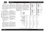
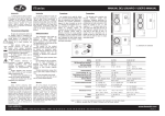
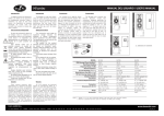
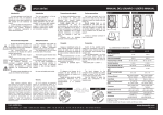
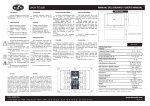
1
factor series
With the models comprising a line
transformer, it is possible to select the
loudspeaker's power by using a multi-step
transformer, following the instructions shown
on the label (see figure below). We
recommend using the highest level of
distributed line voltage as this results in fewer
losses in the actual cabling.
factor 5 / factor 5T
factor 8 / factor 8T
230
270
factor 5
MODEL factor 5W
RMS (Average) Power Handling
(1)
80 W
Transformer RMS Power Handling
Peak Power Handling
Frequency Range
Rated Maximum Peak SPL at 1 m
Nominal -6 dB Beamwidths
(average, 500 Hz to 10 kHz)
Enclosure Material
Color
Transducers/Replacement Parts
Connector
factor 8
factor 8W
factor 8T
factor 8TW
factor 9T
factor 9TW
factor 12
factor 12W
100 W
100 W
150 W
200 W
60 W
60 W
320 W
320 W
400 W
400 W
600 W
800 W
80 Hz - 23 kHz
80 Hz - 21 kHz
55 Hz - 24 kHz
55 Hz - 22 kHz
60 Hz - 20 kHz
45 Hz - 17 kHz
8 ohms
LINE
8 ohms
LINE
LINE
8 ohms
100V, 70V, 50V
100V, 70V, 50V
90 dB SPL
90 dB SPL
91 dB SPL
91 dB SPL
93 dB SPL
94 dB SPL
115 dB
114 dB
117 dB
115 dB
115 dB
123 dB
140° H x 120° V
140° H x 120° V
145° H x 135° V
145° H x 135° V
95° H x 90° V
85° H x 80° V
Polypropylene
Polypropylene
Polypropylene
Polypropylene
Polypropylene
Polypropylene
Black or White (W)
Black or White (W)
Black or White (W)
Black or White (W)
Black or White (W)
Black or White (W)
LF: G-5 /G-5
LF: G-5 /G-5
LF: G-8 /G-8
LF: G-8 /G-8
LF: B-8 /B-8
LF: G-12/GM G-12
HF: TWT-5/TWT-5
HF: TWT-5/TWT-5
HF: TWT-8/TWT-8
HF: TWT-8/TWT-8
HF: TWT-SR-10/TWT-SR-10
HF: M-30/GM M-50
Push Terminals
Push Terminals
Push Terminals
Push Terminals
Push Terminals
Push Terminals
44 x 27 x 23 cm
44 x 27 x 23 cm
58 x 40 x 31 cm
Dimensions (H x W x D) 23 x 15 x 15.5 cm 23 x 15 x 15.5 cm 44 x 27 x 23 cm
Weight
Accessories (optional)
310
80 W
100V, 70V, 50V
(2)
All D.A.S. products are warrantied
against any manufacturing defect for a
period of 2 years from date of purchase.
The warranty
ex-cludes damage from
incorrect or misuseuse of the product. All
warranty repairs must be exclusively
undertaken by the factory or any of its
authorized service centers. To claim a
warranty repair, do not open or intend to
repair the product. Return the damaged
unit, at shippers risk and freight prepaid, to
the nearest service center with a copy of
the purchase invoice.
400
factor 5T
factor 5TW
60 W
Warranty
On-axis Sensitivity 1 W / 1 m
Todos nuestros productos están
garantizados por un periodo de 24 meses
desde la fecha de compra. Las garantías
sólo serán válidas si son por un defecto de
fabricación y en ningún caso por un uso
incorrecto del producto. La reparación en
garantía cubre la reposición de las partes
defectuosas. Otros cargos como portes y
seguros, son a cargo del comprador en
todos los casos. Para solicitar reparación
en garantía es imprescindible que el
producto no haya sido previamente
manipulado e incluir una fotocopia de la
factura de compra.
230
270
ALL DIMENSIONS IN MILIMETERS
For the other IP54 models two Neutrik
Speakon model NL4 connectors, designed
specifically for loudspeakers, are used to
ensure
both
professional
and
safe
connection. With these the positive is pin '+1'
and negative is '-1'. To plug a cable into a
unit, insert the male plug into any of the
enclosure's sockets and turn the male plug to
the right so that it is locked. The two
connectors are in parallel (all pins) so that
either one of them can be used for input or
output (see figure below).
Nominal Impedance
Garantía
155
580
The exclamation point inside an
equilateral triangle indicates the existence of
internal components whose substitution may
affect safety. The specifications can be found
on the rear label of the product.
This symbol on the product indicates
that this product should not be treated as
household waste. Instead it shall be handed
over to the appicable collection point for the
recycling of electrical and electronic
equipment.
The double square indicates Class II
device.
If the device is not IP-54 version, do not
expose to rain or moisture.
Do not place loudspeakers in proximity
to devices sensitive to magnetic fields such
as television monitors or data storage
magnetic material.
Working temperature ranges from 15ºC
to 35ºC with a relative humidity of 75%
(except IP-54 devices).
No user serviceable parts inside.
Clean only with a dry cloth. Do not use
any solvent based cleaners.
For factor 5 IP54 models, connect the
cables through the snake (between 6mm and
8mm in diameter) and through the nut and
water-tight closure (see figure below). Then
connect the cable to the crimp connectors
ensuring that it is completely sealed.
150
factor 12
Safety Precautions
Most of the factor series units comprise
red and black spring loaded push terminals
connectors for positive and negative
connections respectively. The amplifier should
be switched off before any connections are
made. Peel back approximately 10mm of the
outer cable insulation and insert the cable
into the correct terminal so that the
conductor is not visible (see figure below).
440
El signo de exclamación dentro de un
triángulo indica la existencia de componentes
internos cuyo reemplazo puede afectar a la
seguridad.
Las
especificaciones
se
encuentran en la etiqueta de la parte
posterior del producto.
Este símbolo indica que el presente
producto no puede ser tratado como residuo
doméstico normal, sino que debe entregarse
en el correspondiente punto de recogida de
equipos eléctricos y eléctronicos.
El doble recuadro indica que es un
equipo Clase II.
No exponga este equipo a lluvia o
humedad (si no es versión IP-54).
No emplace altavoces en proximidad a
equipos sensibles a campos magnéticos,
tales como monitores de televisión o material
magnético de almacenamiento de datos.
Equipo diseñado para funcionar entre
15ºC y 35ºC con una humedad relativa
máxima del 75% (excepto equipos IP-54).
No existen partes ajustables por el
usuario en el interior de este equipo.
Limpie con un paño seco. No use
limpiadores con disolventes.
La mayoría de los modelos de la serie
factor utilizan terminales de presión rojo/negro
para las conexiones posi-tivo/negativo,
respectivamente. Antes de realizar cualquier
conexión es recomendable tener apagado el
amplificador. Pele aproximádamente 10mm
del aislante del cable e introdúzcalo en el
terminal correspondiente, de forma que
quede oculto el conductor (ver figura más
abajo).
En las versiones de factor 5 IP54, conecte
los cables pasando la manguera (de entre 6 y
8 mm de diámetro), a través de la tuerca y el
cierre de seguridad contra el agua (ver figura
más abajo). Proceda a conectar el cable en
los terminales de presión y apriete la tuerca
del cierre de seguridad comprobando que se
consigue un sellado perfecto.
En las demás versiones IP54, se utilizan
dos conectores Neutrik Speakon NL4 que
son específicos para altavoces y permiten
una conexión profesional y segura. En ellos el
positivo es el pin ‘+1’ mientras que el
negativo es el ‘-1’. Para enchufar un cable a
una caja, inserte el conector macho en
cualquiera de las entradas de la caja y gire el
conector macho hacia la derecha, momento
en el que quedará bloqueado. Los dos
conectores están en paralelo (todos los
pines), de forma que cualquiera de ellos
puede usarse indistintamente como entrada
o salida (ver figura más abajo).
Las versiones con transformador de línea
permiten seleccionar la potencia de la caja
con un conmutador multi-paso y siguiendo
las indicaciones de la etiqueta (ver figura más
abajo). Se recomienda el uso del valor mayor
de voltaje de línea distribuida pues es el que
tiene menores perdidas en el cableado.
Connections
440
Precauciones de Seguridad
The factor series, has been designed to
meet the demands of sound installation in
today's diverse venues. The professional
sound contractor will find the factor series to
be a reliable set of tools for resolving even the
most critical installation. The aesthetically
pleasing product designs integrate perfectly
with today's architecture making the factor
series ideal for installation in restaurants, bars,
offices and commercial centers.
Conexiones
230
La serie factor ha sido diseñada para
resolver múltiples exigencias de sonorización
en
los
espacios
más
diversos,
proporcionando una extensa gama de
herramientas que le permite resolver las
instalaciones más críticas. Este conjunto de
recintos estéticamente atractivos ofrecen una
fácil integración en cualquier espacio
arquitectónico moderno y actual como son
restaurantes, cafeterías, boutiques, oficinas y
grandes espacios comerciales.
Introduction
factor 9T
Introducción
MANUAL DEL USUARIO / USER’S MANUAL
9.1 x 5.9 x 6.1 in
9.1 x 5.9 x 6.1 in
17.5 x 10.5 x 9 in
17.5 x 10.5 x 9 in
17.5 x 10.5 x 9 in
23 x 16 x 12 in
2.8 kg (6.2 lb)
3.5 kg (7.7 lb)
7.4 kg (16.5 lb)
8.1 kg (18 lb)
8.1 kg (18 lb)
15.7 kg (34.5 lb)
AX-5
AX-5
AX-5/AX-5W
AX-5/AX-5W
AX-5/AX-5W
ANL-1
AX-5W
AX-5W
AX-8/AX-8W
AX-8/AX-8W
AX-8/AX-8W
AX-12/15W
FUN-12
TRD-2
Notes: 1. Based on a 2 hour test continuously applying 6 dB crest factor pink noise (IEC shaped).
2. Maximum calculated Peak SPL based on sensitivity and RMS power handling.
D.A.S. AUDIO S.A.
C/ Islas Baleares, 24 - 46988 - Fuente del Jarro. Valencia - SPAIN - Tel. 96 134 05 25 - Tel. Intl. +34 96 134 08 60 - Fax +34 96 134 06 07
www.dasaudio.com
UM_FAC_04
factor series
Precauciones de colgado
Los tacos suministrados son para
uso en paredes de ladrillo, para cualquier otro material deberá proveerse
de los tacos adecuados.
D.A.S. Audio S.A. no se
responsabilizará
de
usos
no
recomendados de estos soportes, ya
sea la no utilización de los tacos o
tornillos suministrados, o la sujeción de
la caja a superficies que no tengan
suficiente resistencia a la tracción,
como son escayola y yeso, por
ejemplo.
Contacte con un instalador
autorizado si tiene cualquier duda.
MANUAL DEL USUARIO / USER’S MANUAL
Surface precautions
Wall plugs provided are to be
used in brick walls only. For other wall
mate-rials, source the suitable wall
plug be-fore use.
D.A.S. Audio S.A. is not
responsible for use other than the
recommended. Use only screws and
wall plugs supplied on surfaces that
will provide sufficient support. Do not
use on surfaces such as plaster and
gypsum.
Contact a licensed contractor if
there is any doubt.
AXC-ZT
TRD-2
AX-12/15
Emplazamiento
Coloque los altavoces por delante
de los micrófonos, si los utiliza. La
realimentación (feedback) o acople
ocurre cuando los micrófonos recogen
el sonido que sale de los altavoces y
los introducen de nuevo en el sistema.
La realimentación puede provocar
graves daños en su caja. Si el espacio
es limitado, dirija los altavoces hacia
donde no estén los micrófonos, para
reducir el acople.
Si usa platos giradiscos, coloque los
altavoces
lejos
de
los
platos
giradiscos. Si la aguja del plato
giradiscos recoge la señal de los
altavoces y la re-amplifica se produce
un acople de las bajas frecuencias. Se
recomienda el uso de una base sólida
en el plato giradiscos.
Utilización sobre trípode
Sólo la factor 12 con adaptador para
trípode,
permite
esta
AXC-ZT ,
posibilidad.
La altura máxima de seguridad
desde el suelo a la base de la caja,
montada sobre trípode modelo TRD-2 y
con pies a su máxima extensión, es de
140 cm.
Tenga cuidado de no elevar la caja a
una altura excesiva que pueda permitir
que se caiga con facilidad.
Coloque los altavoces lo más alto
posible. Para un mejor resultado trate
de colocar el difusor (trompeta) de
agudos por encima de las cabezas de
la audiencia. Si los altavoces están
colocados demasiado bajos, el público
situado al final de la audiencia no
recibirá un sonido con la calidad
adecuada.
Placement
If you are using microphones, place
the loudspeakers in front of them.
Feedback
occurs
when
the
microphones pick up the sound
coming from the loudspeakers and
send it through the system again.
Feedback can seriously damage your
unit. If you only have limited space,
point the loudspeakers to an area
where there are no microphones to
reduce feedback.
If you use turntables, place the
loudspeakers far away from the
turntables. If the turntable's needle
picks up the signal from the
loudspeakers, it re-amplifies it and low
frequency feedback occurs. We
recommend that the turntable has a
solid base.
Tripod use
This is only possible with the factor
12 model and with tripod socket type
AXC-ZT.
The maximum safety height from the
floor to the base of the unit, mounted
on model TRD-2 tripod with its legs fully
extended is 140 cm.
Be careful not to increase the height
of the unit so much that it can easily
fall down.
Place the loudspeakers as high up
as possible. For best results, try to
place the high frequency horn above
the heads of the audience. If the
loudspeakers are too low, the audience
at the back will not be able to hear
quality sound.
D.A.S. AUDIO S.A.
C/ Islas Baleares, 24 - 46988 - Fuente del Jarro. Valencia - SPAIN - Tel. 96 134 05 25 - Tel. Intl. +34 96 134 08 60 - Fax +34 96 134 06 07
Fijación a paredes y techo
Mounting to walls and ceilings
Todos los modelos disponen de
soportes opcionales para su fijación a
paredes y/o techos.
Los soportes y demás accesorios
de
colgado,
deberán
revisarse
regularmente
y
las
unidades
sospechosas desechadas.
Every model has optional supports
for fixing them to walls and/or ceilings.
Se debe tener mucho cuidado con
los soportes, usando sólo los
recomendados,
para
realizar
la
instalación con plenas garantías de
seguridad. No pueden colgarse unas
cajas de otras.
Great care should be taken when
using
supports
and
only
the
recommended ones should be used to
ensure a guaranteed safe installation.
The units should not be hung from
each other.
Si se cuelga una factor 12, se
utilizarán los dos puntos inferiores y
dos traseros para la angulación.
El ANL-1 es un juego de cuatro
cáncamos (anillas de elevación o
eyebolts) y cuatro mallas rápidas
(carabiners) como accesorio para el
colgado de factor 12.
If a factor 12 model is flown, the two
points underneath and at the back can
be used for angling it.
The ANL-1 is a set of four eyebolts
and four carabiners used for flying
factor 12 units.
These supports and other rigging
accessories should be regularly
checked and any with flaws should be
thrown away.
AXW-1
AX-5
ANL-1
www.dasaudio.com