1
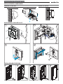
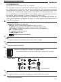
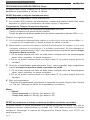
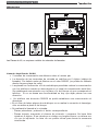
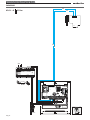
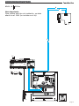
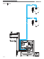
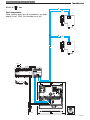
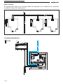
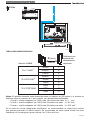
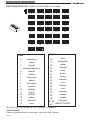
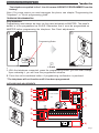
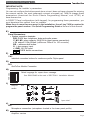
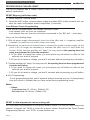
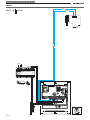
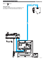
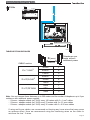
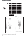
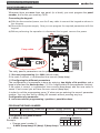
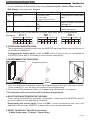
KIT AUDIO CITYLINE DUOX 1-2L AUDIO CITYLINE DUOX KIT 1-2L MANUAL DE INSTALADOR Y USUARIO USER& INSTALLER’S MANUAL E S PA Ñ O L ENGLISH DUO X CITYLINE CITYLINE KIT KIT 1-2L 1-2L DUOX X DUOX DUO Publicación técnica de caracter informativo editada por FERMAX ELECTRONICA S.A.U. FERMAX ELECTRONICA, en su política de mejora constante, se reserva el derecho a modificar el contenido de este documento así como las características de los productos que en él se refieren en cualquier momento y sin previo aviso. Cualquier modificación será reflejada en posteriores ediciones de este documento. ¡ENHORABUENA POR DISPONER DE UN PRODUCTO DE CALIDAD! Fermax electrónica desarrolla y fabrica equipos de prestigio que cumplen los más altos estándares de diseño y tecnología. Su teléfono FERMAX le permitirá comunicarse con la placa de calle y abrir la puerta de entrada si así lo desea. Esperamos disfrute de sus funcionalidades. www.fermax.com «KIT AUDIO CITYLINE DUOX 1-2L» Cod. 97704EIc V09_13 Pag 2 ESPAÑOL DUO X CITYLINE CITYLINE KIT KIT 1-2L 1-2L DUOX X DUOX DUO INDICE SECCION I - MANUAL DEL INSTALADOR .................................................................. 5 Instalación del Alimentador ............................................................................ 6 Instalación de la placa de calle ..................................................................... 6 Teléfono ............................................................................................................ 6 - Instalación ................................................................................................................... 6 - Programación ............................................................................................................. 7 Ajustes finales de placa ................................................................................. 7 Restaurar a valores de fábrica: Reset ............................................................. 10 - Reset Mapeado .......................................................................................................... 10 - Programación Tiempos de apertura .......................................................................... 10 - RESET parámetros a valores por defecto de fábrica (mediante un teclado) ........ 10 Precableado ..................................................................................................... 11 Características Técnicas ................................................................................ 12 Esquemas de cableado .................................................................................. 13 SECCION II - MANUAL DE USUARIO ......................................................................... 21 Teléfono Loft ..................................................................................................... 22 Funcionamiento ............................................................................................... 22 Selección Tono de llamada ............................................................................ 23 GUÍA RÁPIDA DE PROGRAMACIÓN ........................................................................... 24 Pag 3 DUO X CITYLINE CITYLINE KIT KIT 1-2L 1-2L DUOX X DUOX DUO Pag 4 DUO X CITYLINE CITYLINE KIT KIT 1-2L 1-2L DUOX X DUOX DUO Sección I - Manual del Instalador Pag 5 DUO X CITYLINE CITYLINE KIT KIT 1-2L 1-2L DUOX X DUOX DUO INSTALACIÓN DEL ALIMENTADOR Instalación en carril DIN Fijación con tornillos Desmontaje Montaje MA DE 5060 Hz. +1 IN SP AI N 50V A MA X. 8V 12 V 1. 5A 1A FU EN TE A KIT LIME DIG NTAC ITA ION L INSTALACIÓN PLACA DE CALLE 1 2 1 5.5.70m 7f ee t 3 4 A MARI A LORC INSTALACIÓN DEL TELÉFONO 1 Pag 6 2 3 4 5 DUO X CITYLINE CITYLINE KIT KIT 1-2L 1-2L DUOX X DUOX DUO ¡El teléfono, suministrado en el kit de 1 línea YA SALE PROGRAMADO de fábrica! Nota: Si por algún motivo necesita reprogramar el teléfono, ver capítulo «Programación del Teléfono» o «Guía rápida de programación». PROGRAMACIÓN DEL TELÉFONO Nota muy importante: La programación se realiza siempre desde la placa activada como MÁSTER. La placa sale programada por defecto como SECUNDARIA (esclava). Recuerde que debe programarla como placa MÁSTER antes de realizar la programación del teléfono. Ver Ajustes de la Placa. 1 2 Botón de Programación 5 A < 2 min 1. Con el teléfono conectado pulse el botón de programación (se escucha un bip). Al soltar se oirá le entrada en programación. 2. Pulse el botón de llamada a vivienda. Se produce la confirmación de programación. * El teléfono no funcionará mientras no haya sido programado. AJUSTES DE LA PLACA CN1 PACK EXTENSION D) C) SW1 DL2 DL2 LED A B C D E F ON B) DUOX AMPLIFICADOR AMPLIFIER CN1 CN9 E) CN2 CN3 I) IDIOMA LANGUAGE SW1 PROG CN9 TAMPER ONE TO ONE H) AUDIO MIC A) EXIT BUS P2 B B C NO NC J) 18Vdc +12 BS - S + GND P1 F) G) NC NO C VERSION : K) Pag 7 DUO X CITYLINE CITYLINE KIT KIT 1-2L 1-2L DUOX X DUOX DUO A) CN1 Conexión módulo de extensión de llamadas, teclado B) CN9 Conexión Tamper (mediante conector stocko macho paso 2mm). C) DL2 Led de Modo: • Intermitente lento (2 parpadeos / 3 seg): Modo Conserjería Día o Mixto. • Intermitente lento (1 parpadeo / 1 seg): Programación Inversa o Secuencial. Ver Manual Avanzado de Programación DUOX cod. 97699. • Apagado: reposo o Modo Conserjería Noche. D) Placa MÁSTER: • La programación se realiza siempre desde la placa activada como MÁSTER. • En cualquier instalación sólo puede haber una placa MÁSTER a la vez, ya sea una instalación de un sólo bloque o de varios, ya esté configurada como placa de subbloque, de bloque o entrada general. • Una placa de calle se configura como MÁSTER mediante el pulsador SW1 del amplificador. Si se pulsa el botón SW1 3 veces consecutivas rápidas se activará la placa como MÁSTER y se oirá un tono de confirmación (bip-bip). • Cuando se selecciona una placa como MÁSTER, ésta avisa al resto de la situación y si hubiera anteriormente una así configurada, dejará de serlo automáticamente. • En caso de haber varios bloques en una instalación será recomendable utilizar la placa de la entrada general como MÁSTER ya que permite programar todos los teléfonos de ésta. • Es recomendable una vez terminada la configuración de los terminales desactivar la placa MÁSTER para evitar reprogramaciones de terminales accidentales. • La placa se desactiva del modo máster siguiendo el mismo procedimiento de activación: 3 pulsaciones seguidas rápidas del botón SW1. Se oirá un tono de desactivación (bip-bop). Configuración - Programación del Amplificador El amplificador DUOX se puede configurar para permitir un funcionamiento como placa de entrada general, entrada de bloque o entrada de sub-bloque. • El sistema DUOX emplea direcciones de terminal de vivienda de 6 dígitos. • Los dígitos del código de llamada se organizan de la siguiente manera: BBSSNN: - BB: indica el número de Bloque, (de 00 a 99). - SS: indica el número de sub-bloque, (de 00 a 99). - NN: indica el número de vivienda del sub-bloque, (de 00 a 99). No es necesario segregar la instalación según ésta jerarquía ya que el sistema se adapta a las necesidades de la instalación. Pag 8 DUO X CITYLINE CITYLINE KIT KIT 1-2L 1-2L DUOX X DUOX DUO NOTA IMPORTANTE: Programación de parámetros por el instalador. No es posible configurar la placa de pulsadores por si sola, ya que no se dispone de un teclado para introducir los valores numéricos. Es necesario conectar temporalmente un teclado (ref. 7439) para modificar dichos parámetros (descargar el manual de Programación Placas Direct, cod. 97701, en www.fermax.com). En configuraciones de Placa DIRECT (con teclado), para la programación de estos parámetros, debe descargar el mismo manual de nuestra web. Cuando haya más de una placa en la instalación, se necesitará el teclado ref. 7439, para programar el número de placa. Ver Guía rápida de Programación al final de este manual. E) Conectores Placa: • Bornas de Conexión del sistema: B,B: Bus DUOX: alimentación teléfonos, datos y audio. C, NO, NC: contactos relé, 2A@30Vdc (conexión abrepuertas). +12: salida12 Vdc-250mA (máximo 500mA durante 100 segundos). BS, -: pulsador zaguán. S, -: entrada sensor de puerta. +, GND: entrada 18 Vdc. P1-P2: conexión pulsador/es. F) CN2 Conexión pulsadores individuales placa perfil continuo Cityline G) CN3 Conexión Módulo OneToOne H) ON A B C D E F Selección del idioma del mensaje de «puerta abierta». Ver CODIFICACIÓN al final de la SECCIÓN I: Manual del Instalador. I) Ajuste audio “puerta abierta” J) MIC Conexión micrófono (micrófono ubicado en el perfil inferior de la placa) K) Versión del amplificador Pag 9 DUO X CITYLINE CITYLINE KIT KIT 1-2L 1-2L DUOX X DUOX DUO RESTAURAR A VALORES DE FÁBRICA: Reset El amplificador DUOX dispone de la función de «Reset» que permite restaurar los parámetros programados a valores de fábrica. RESET Mapeado (codigo de llamada pulsador) 1º- Resetear el amplificador: quitar alimentación. 2º- Con el botón SW1 pulsado, dar alimentación y mantener pulsado el botón SW1 hasta escuchar un sonido de confirmación de reset: bip-bip (5 segundos). Programación Tiempos de apertura de puerta Los tiempos de activación de abrepuerta programables son dos: - Tiempo de apertura de puerta desde vivienda - Tiempo de apertura de puerta desde botón de salida (conectado a bornas «BS» y «-»). Realizar los siguientes pasos: 1º. Con la alimentación desconectada, realice un cortocircuito entre las bornas «Bs» y «» (negativo) del amplificador (o pulsar el botón de salida, si existe). 2º. Manteniendo el cortocircuito anterior conecte la alimentación del sistema, (ya no será necesario mantener el cortocircuito o el pulsador presionado). En ese momento el amplificador generará tantos ‘‘bips’’ como segundos haya programado para el tiempo de apertura desde vivienda. 2.1.Si se desea cambiar ese valor se debe pulsar cualquier botón de llamada tantas veces como segundos se quiera programar. 2.2.Si no se quiere cambiar basta con dejar pasar 5" sin pulsar ningún botón de llamada. 3º. Después el amplificador generará tantos ‘‘bips’’ como segundos haya programado para el el tiempo de apertura desde el pulsador de salida. 3.1.Si se desea cambiar ese valor se debe pulsar cualquier botón de llamada tantas veces como segundos se quiera programar. 3.2.Si no se quiere cambiar basta con dejar pasar 5" sin pulsar ningún botón de llamada. 4º. Salir de programación: Para salir de programación, permanecer 5 segundos sin pulsar ninguna tecla. Sonará un ‘‘bip bip’’ indicando la salida de programación de tiempos. Notas: • Valores: - Tiempo abrepuertas: 01..99 seg. (por defecto: 03). - Tiempo botón salida: 00..99 seg. (por defecto: 06). RESET de parámetros a valores por defecto de fábrica (mediante un teclado) Se puede realizar un Reset de parámetros a valores por defecto de fábrica. Para ello es necesario conectar temporalmente un teclado (ref. 7439) para introducir los valores numéricos. Descargar el manual de Programación Placas Direct, cod. 97701, en www.fermax.com. Pag 10 DUO X CITYLINE CITYLINE KIT KIT 1-2L 1-2L DUOX X DUOX DUO PRECABLEADO DUOX AMPLIFICADOR AMPLIFIER CN1 CN1 PACK EXTENSION SW1 DL2 LED IDIOMA LANGUAGE SW1 PROG CN9 TAMPER ONE TO ONE CN2 CN3 AUDIO MIC DL2 A B C D E F ON CN9 EXIT BUS P2 B B C NO NC 18Vdc +12 BS - S + GND P1 + CP NC C VERSION : NO 1 2 1 Las Placas de Kit, no requieren módulo de extensión de llamadas. Llamada Amplificador DUOX: • 2 canales de conversación simultáneos sobre el mismo par. • La dirección de los terminales de vivienda se codifica con 6 dígitos (código de llamada). Por defecto salen de fábrica con el valor 000000, (no puede ser llamado desde ninguna placa de calle). • Las placas con la dirección «0» de cada bloque permitirán realizar la comunicación con los teléfonos cuando se descuelguen si el canal de comunicación está libre. Se establecerá comunicación con la placa «0» del bloque al que corresponde el teléfono. Si no se desea esa funcionalidad no hay que dejar placas con esa dirección. • Un teléfono con dirección 000000 no podrá establecer una comunicación al descolgar. • En el caso de haber placas de sub-bloque no se realiza la conexión al descolgar, sólo se realiza a placa 0 de bloque. • Se realizará la llamada a la vivienda: - Placas pulsadores: pulsando el botón correspondiente. - Placas teclado: marcando el número de vivienda + campana. No hace falta introducir 6 dígitos. Si se introduce un código con longitud menor, se rellena con «0» por la izquierda. La letra «A» se puede utilizar para borrar la secuencia introducida. Pag 11 DUO X CITYLINE CITYLINE KIT KIT 1-2L 1-2L DUOX X DUOX DUO CARACTERÍSTICAS TÉCNICAS Alimentación Consumo en reposo audio activo IP43 / IK07 iluminación Potencia audio sentido vivienda-calle Potencia audio sentido calle-vivienda Temperatura de funcionamiento 18 Vdc 94 mA 550 mA 35 mA 1W 0,15 W [-10º , +60ºC] [14º, 140ºF] Volumen regulable en ambos sentidos Valores: - Tiempo activación abrepuertas: 01..99 seg. (por defecto: 03). - Tiempo activación botón salida: 00..99 seg. (por defecto: 06). - Tiempo de conversación máximo: 90 seg. - Tipo de Placa: sub-bloque/bloque/general, (por defecto: bloque). - Número Bloque: 00..99, (por defecto: 00). - Número Sub-Bloque: 00..99, (por defecto: 00). - Número Placa: 0..9, (por defecto: 0). - Tiempo sensor de puerta: 000..250, (por defecto: 000, no activo). - Código apertura: 0000..9999, (por defecto: no activo). - Código programación: 0000..9999, (por defecto: 4444). - Placa MÁSTER: no activa. - Volumen monitorización: 0..9, (por defecto: 5). - Tiempo en programación secuencial de pulsadores tras cese actividad: 60 seg. - Tiempo en programación inversa de pulsadores tras cese actividad: 300 seg. Capacidades: • Llamadas desde Placa Pulsadores: 99. • Llamadas desde Placa Teclado: - Sub-Bloque: 99. - Bloque: 9999. - Entrada General: 999999. • Número de Placas: - Entradas Generales: 10. - Bloque: 10. - Sub-Bloque: 10. Alimentación Consumo (±5%) en reposo máximo Número máximo de terminales por vivienda Dirección teléfono: 6 dígitos decimales Temperatura de funcionamiento Altavoz Resist. dinámica 50 Ω Micrófono: Electret Melodías de Llamada seleccionables Número de canales de conversación: 2 por BUS Pag 12 18 Vdc 16 mA 190 mA 3 000001...999999 [-5º, +40ºC] 1.75" 16 Ω DUO X CITYLINE CITYLINE KIT KIT 1-2L 1-2L DUOX X DUOX DUO Esquemas de cableado Pag 13 DUO X CITYLINE CITYLINE KIT KIT 1-2L 1-2L DUOX X DUOX DUO CABLEADO B Kit 1L & 12 Vac B CN1 SW3 B B Vac 18 Vdc + -+ - ~ 240V ~ INPUT 100-240 V ; 1,2A 50-60 Hz 18Vdc+12Vac ON OVERLOAD OUTPUT 18 V ; 1.5 12 V ; 12 Vac ~ ~ 12 Vac MADE IN SPAIN 50-60 Hz. +1 50VA 8V 12 V MAX. 1. 5A 1A FUENT E ALIME KIT DIGITNTACIO AL N 30 m DUOX CN1 CN1 PACK EXTENSION SW1 DL2 DL2 LED AMPLIFICADOR AMPLIFIER A B C D E F ON CN9 IDIOMA LANGUAGE SW1 PROG CN9 TAMPER ONE TO ONE CN2 CN3 EXIT BUS P2 B B 18Vdc C NO NC +12 NC NO 12 Vac Pag 14 AUDIO MIC D. max. BS - C S + GND P1 VERSION : DUO X CITYLINE CITYLINE KIT KIT 1-2L 1-2L DUOX X DUOX DUO Kit 1L & 12 Vac B B Nota importante: Para realizar este tipo de instalación, se debe añadir la ref. 3243 (no incluida en el kit). CN1 SW3 B B Vac 18 Vdc + -+ - ~ 240V ~ 24/18 Vdc IN MADE IN SPAIN 100-240 V ; 1,2A 50-60 Hz 18Vdc+12Vac ON OVERLOAD INPUT BUS2 24Vdc/2A DUOX 18Vdc/2A OUTPUT OUTPUT PREV BUS BUS2/DUOX POWER SUPPLY ADAPTER MODULE REF. 3243 Ref. 3243 BUS2 24Vdc/2A DUOX 18Vdc/2A 18 V ; 1.5 12 V ; 12 Vac ~ ~ PWR BUS PWR BUS 12 Vac D. max. MADE IN SPAIN 50-60 Hz. +1 50VA 8V 12 V MAX. 1. 5A 1A FUENT E ALIME KIT DIGITNTACIO AL N 30 m DUOX CN1 CN1 PACK EXTENSION SW1 DL2 DL2 LED AMPLIFICADOR AMPLIFIER A B C D E F ON CN9 IDIOMA LANGUAGE SW1 PROG CN9 TAMPER ONE TO ONE CN2 CN3 AUDIO MIC INPUT EXIT BUS P2 B B 18Vdc C NO NC +12 NC BS - C S + GND P1 VERSION : NO 12 Vac Pag 15 DUO X CITYLINE CITYLINE KIT KIT 1-2L 1-2L DUOX X DUOX DUO Kit 2L & 12 Vac B B CN1 SW3 B B CN1 B B SW3 Vac 18 Vdc + -+ - ~ 240V ~ INPUT 100-240 V ; 1,2A 50-60 Hz 18Vdc+12Vac ON OVERLOAD OUTPUT 18 V ; 1.5 12 V ; 12 Vac ~ ~ 12 Vac MADE IN SPAIN 50-60 Hz. +1 50VA 8V 12 V MAX. 1. 5A 1A FUENT E ALIME KIT DIGITNTACIO AL N 30 m DUOX AMPLIFICADOR AMPLIFIER CN1 CN1 PACK EXTENSION SW1 DL2 DL2 LED A B C D E F ON CN9 IDIOMA LANGUAGE SW1 PROG CN9 TAMPER ONE TO ONE CN2 CN3 EXIT BUS P2 B B C NO NC 18Vdc +12 NC NO 12 Vac Pag 16 AUDIO MIC D. max. BS - C S + GND P1 VERSION : DUO X CITYLINE CITYLINE KIT KIT 1-2L 1-2L DUOX X DUOX DUO Kit 2L & 12 Vac B B Nota importante: Para realizar este tipo de instalación, se debe añadir la ref. 3243 (no incluida en el kit). CN1 SW3 B B CN1 B B SW3 Vac 18 Vdc + -+ - ~ 240V ~ 100-240 V ; 1,2A 50-60 Hz 24/18 Vdc IN 18Vdc+12Vac MADE IN SPAIN ON OVERLOAD OUTPUT PREV BUS BUS2/DUOX POWER SUPPLY ADAPTER MODULE REF. 3243 INPUT BUS2 24Vdc/2A DUOX 18Vdc/2A OUTPUT Ref. 3243 BUS2 24Vdc/2A DUOX 18Vdc/2A 18 V ; 1.5 12 V ; 12 Vac ~ ~ PWR BUS PWR BUS 12 Vac D. max. MADE IN SPAIN 50-60 Hz. +1 50VA 8V 12 V MAX. 1. 5A 1A FUENT E ALIME KIT DIGITNTACIO AL N 30 m DUOX AMPLIFICADOR AMPLIFIER CN1 CN1 PACK EXTENSION SW1 DL2 DL2 LED A B C D E F ON CN9 IDIOMA LANGUAGE SW1 PROG CN9 TAMPER ONE TO ONE CN2 CN3 AUDIO MIC INPUT EXIT BUS P2 B B C NO NC 18Vdc +12 NC BS - C S + GND P1 VERSION : NO 12 Vac Pag 17 DUO X CITYLINE CITYLINE KIT KIT 1-2L 1-2L DUOX X DUOX DUO AMPLIACIONES El equipamiento básico por vivienda puede ser ampliado con 2 teléfonos sin necesidad de añadir fuentes de alimentación. B CN1 B CN1 B CN1 B SW3 SW3 SW3 CONEXIÓN ABREPUERTAS Vac 12 Vac 18 Vdc + -+ - ~ 240V ~ INPUT 100-240 V ; 1,2A 50-60 Hz 18Vdc+12Vac B ON OVERLOAD OUTPUT 18 V ; 1.5 12 V ; 12 Vac B ~ ~ 12 Vac DUOX AMPLIFICADOR AMPLIFIER CN1 CN1 PACK EXTENSION SW1 DL2 LED A B C D E F IDIOMA LANGUAGE SW1 PROG CN9 TAMPER ONE TO ONE CN2 CN3 EXIT BUS P2 B B C NO NC 18Vdc +12 NC NO 12 Vac Pag 18 AUDIO MIC DL2 ON CN9 BS - C S + GND P1 VERSION : DUO X CITYLINE CITYLINE KIT KIT 1-2L 1-2L DUOX X DUOX DUO Vac 12 Vdc 18 Vdc + -+ - ~ 240V ~ 18Vdc+12Vac B ON OVERLOAD OUTPUT 18 V ; 1.5 12 V ; 12 Vac B ~ ~ DUOX AMPLIFICADOR AMPLIFIER CN1 CN1 PACK EXTENSION SW1 DL2 DL2 LED A B C D E F ON CN9 AUDIO IDIOMA LANGUAGE SW1 PROG CN9 TAMPER ONE TO ONE CN2 CN3 MIC INPUT 100-240 V ; 1,2A 50-60 Hz EXIT BUS P2 B B C NO NC 18Vdc +12 NC BS - S + GND P1 C VERSION : NO 12Vdc TABLAS SECCIONES DISTANCIAS Teléfonos por vivienda sin alimentación adicional D (max) Sección CABLE 2x1 mm2 2 x 0,5 mm2 2 x 0,22 mm2 metros 300m 200m 120m 200m 100m 60m 90m 45m 30m 1 2 3 1 2 3 1 2 3 Notas: Es posible aumentar estas distancias hasta un máximo de 300 metros y el número de teléfonos hasta un máximo de 3 por vivienda, con alimentadores adicionales. - 1 Fuente + módulo adaptador (ref. 3243) cada 140 metros con cable 2 x 1 mm2 - 1 Fuente + módulo adaptador (ref. 3243) cada 70 metros con cable 2 x 0,5 mm2 - 1 Fuente + módulo adaptador (ref. 3243) cada 35 metros con cable 2 x 0,22 mm2 En el caso de utilizar mangueras multifilares, es recomendable no dejar hilos sueltos que puedan provocar un efecto antena. Se recomienda en estos casos utilizar los hilos sobrantes de la manguera para reforzar los 2 hilos del bus. Pag 19 DUO X CITYLINE CITYLINE KIT KIT 1-2L 1-2L DUOX X DUOX DUO SINTETIZADOR DE VOZ. CODIFICACIÓN IDIOMAS (Ver tabla). ON ON 12 3 4 5 6 ON 12 3 4 5 6 0 1 ON ON ON ON 12 3 4 5 6 2 3 ON ON 12 3 4 5 6 12 3 4 5 6 12 3 4 5 6 5 6 7 8 ON ON 4 ON 12 3 4 5 6 ON 12 3 4 5 6 12 3 4 5 6 ON 12 3 4 5 6 9 ON 12 3 4 5 6 12 3 4 5 6 12 3 4 5 6 10 11 12 13 O 12 3 4 5 6 12 3 4 5 6 N 1 2 14 3 4 ON ON ON ON ON 5 6 12 3 4 5 6 12 3 4 5 6 12 3 4 5 6 12 3 4 5 6 15 16 17 18 ON ON ON 12 3 4 5 6 12 3 4 5 6 21 20 ON ON 12 3 4 5 6 12 3 4 5 6 25 ON 26 12 3 4 5 6 12 3 4 5 6 22 23 ON 12 3 4 5 6 27 12 3 4 5 6 24 ON 12 3 4 5 6 28 12 3 4 5 6 29 ON 12 3 4 5 6 62 12 3 4 5 6 63 CODE 0 castellano 1 inglés 2 francés 3 holandés/flamenco 4 alemán 5 catalán 6 valenciano 7 balear 8 portugués 9 euskera 10 gallego 11 griego 12 polaco 13 checo 14 eslovaco 15 turco CODE chino 16 persa/farsi 17 árabe 18 noruego 19 finés 20 sueco 21 danés 22 islandés 23 ruso 24 italiano 25 hindi 26 húngaro 27 hebreo 28 croata 29 Campana 30..62 DESACTIVADO 63 Hay posiciones sin idioma: 30...62, (sonará la campana). (*) IMPORTANTE Futuras actualizaciones de idiomas, consultar web Fermax. Pag 20 19 ON ON ON 12 3 4 5 6 DUO X CITYLINE CITYLINE KIT KIT 1-2L 1-2L DUOX X DUOX DUO Sección II - Manual del Usuario Su teléfono FERMAX le permitirá comunicarse con la placa de calle y abrir la puerta de entrada si así lo desea. Esperamos disfrute de sus funcionalidades. Pag 21 DUO X CITYLINE CITYLINE KIT KIT 1-2L 1-2L DUOX X DUOX DUO TELÉFONO LOFT BOTONES - Basic Botón de abrepuertas / llamada a conserje (función disponible según tipo de instalación). · Estando en conversación con la Placa de Calle, al pulsar este botón se activa el abrepuertas. · Con el teléfono colgado, al pulsar este botón se realiza una llamada al conserje (si existe conserjería). FUNCIONAMIENTO Llamada 30 ¸ max. Seg./Sec./Sek. Atender la llamada bla bla bla ... bla bla bla ... max. 90 Seg./Sec./Sek. Pag 22 DUO X CITYLINE CITYLINE KIT KIT 1-2L 1-2L DUOX X DUOX DUO Abrir la puerta al visitante Autoencendido (teléfono ya programado) 90 ¸ max. Seg./Sec./Sek. Si no está programado el teléfono, éste no realizará la función de autoencendido. · Esta funcionalidad es posible con la placa de su mismo bloque, si la placa está en reposo y programada como "0" y existe algún canal de conversación disponible. SELECCIÓN TONO DE LLAMADA Botón abrepuertas + Botón de Programación 1. Con el teléfono conectado pulse el botón de programación (se escucha un bip) y sin soltarlo pulsar el botón de abrepuertas. Se oirá la melodía actual. 2. Una vez en modo programación, pulsar el botón abrepuertas para seleccionar secuencialmente los tonos disponibles. Cada vez que se pulsa el botón abrepuertas, se escucha el tono seleccionado. * Una vez seleccionado el tono de llamada, dejar el teléfono en reposo y transcurridos 10 segundos, sale de programación, (se escucha un bip). Pag 23 DUO X CITYLINE CITYLINE KIT KIT 1-2L 1-2L DUOX X DUOX DUO GUÍA RÁPIDA DE PROGRAMACIÓN 1. CODIFICAR PLACAS Siempre que exista más de una placa (a un bloque), sera necesario programar el número de placa, para ello necesitaremos un teclado 7439. Conexión del teclado: a) Con la alimentación desconectada, Usar el cable de 5 vías para conectar el teclado tal y como muestra el esquema. b) Reconectar la alimentación. Ya se pueden programar los parámetros necesarios mediante el teclado. c) Antes de realizar las operación de desconectar el teclado, quitar la alimentación. CN1 DUOX AMPLIFICADOR AMPLIFIER CN1 CN9 SW1 DL2 LED IDIOMA LANGUAGE SW1 PROG CN9 TAMPER ONE TO ONE CN2 CN3 EXIT BUS P2 B B C NO NC Cable de 5 vías CN1 18Vdc +12 NC BS - C S + GND P1 VERSION : NO ENTRADA/INPUT ARRIVÉE/EINTRITT PUT NTRITT AUDIO MIC DL2 ON A B C D E F CN1 PACK EXTENSION CN1 CN1 MÓDULO TECLADO KEYPAD MODULE MODULE CLAVIER TASTATURMODUL UP SALIDA/OUTPUT SORTIE/AUSGANG CN1 CN2 1 2 3 4 5 6 7 8 9 A 0 B Configurar los parámetros de la placa de calle a través del teclado. 1.1 Acceso a programación: A + 4444 (código por defecto). Si el código es correcto se oirá un tono de confirmación (bip-bip). 1.2 Configuración de los diferentes Parámetros La configuración de un parámetro es introduciendo: dos dígitos de su posición, se oirá un bip y el valor deseado (1, 2, 3 ó 4 dígitos en función del parámetro). Si el valor es correcto se oirá un tono de confirmación (bip-bip) y se guardará el nuevo valor. Si no fuera correcto se escuchará el sonido de error (bip-bop). Para salir de programación se pulsará ‘A’ cuando estemos en la introducción del número de parámetro del menú. También se saldrá automáticamente a los 60" sin pulsar ninguna tecla. Configuración de parámetro: A + Codigo acceso a programación + Posición + Valores Posibles PROGRAMAR el NÚMERO DE PLACA, Posición 06 Parámetro Ajuste Nº Placa (PL) Valores Posibles [defecto] 0-9 [0] Configuración número de placa: A + 4444 + 06 + 0-9 Ejemplo: • Cambio número de placa 2: A 4444 (bip-bip) 06 (bip) 2 (bip-bip) Pag 24 Comentario Número de Placa. PL 2 MARCAR TIPO NÚMERO EG BK SB BK SB PL 2 DUO X CITYLINE CITYLINE KIT KIT 1-2L 1-2L DUOX X DUOX DUO Si su instalacion se caracteriza por tener Entradas Generales, Bloques interiores y/ o Sub-bloques, ademas deberá programar: Posición Parámetro Ajuste 03 Tipo Placa 04 05 Valores Posibles [defecto] Comentario 0: Sub-Bloque (SB) Configuración del tipo de placa. [1]: Bloque (BK) 2: E. General (EG) Número de Bloque al que Nº Bloque (BK) 00-99 pertenece la placa. [00] Número de Sub-Bloque al que Nº Sub-Bloque (BS) 00-99 pertenece la placa. [00] Se recomienda una vez programada cada placa rellenar la pegatina del amplificador. Ejemplos: BK 1 EG 1 MARCAR TIPO NÚMERO MARCAR TIPO EG BK SB BK SB PL NÚMERO EG BK SB BK SB PL 1 SB 1 MARCAR TIPO NÚMERO EG BK SB BK SB PL 1 1 2. CONFIGURAR COMO PLACA MÁSTER La programación se realiza siempre desde la placa MÁSTER y sólo puede haber una en toda la instalación. Configuración placa máster: Pulsar el botón SW1 3 veces consecutivas rápidas se activará la placa como MÁSTER y se oirá un tono de confirmación (bip-bip). 3. PROGRAMACIÓN TELÉFONO 1 Botón de Programación 2 5 A < 2 min 1. Con el teléfono conectado pulse el botón de programación (se escucha un bip). Al soltar se oirá le entrada en programación. 2. Pulse el botón de llamada a vivienda. Se produce la confirmación de programación. * El teléfono no funcionará mientras no haya sido programado. 4. DESACTIVAR MODO MÁSTER EN PLACA Una vez terminada la configuración de los terminales desactivar la placa MÁSTER para evitar reprogramaciones de terminales accidentales. Desactivación placa máster: Pulsar el botón SW1 3 veces consecutivas rápidas y se desactivará la placa como MÁSTER. Se oirá un tono de desactivación (bip-bop). 5. RESET A VALORES DE FÁBRICA (por si es necesario) A 4444 (bip-bip) 13 (bip) 1 (bip-bip) Pag 25 DUO X CITYLINE CITYLINE KIT KIT 1-2L 1-2L DUOX X DUOX DUO Technical document published for information purposes by FERMAX ELECTRONICA S.A.U. FERMAX ELECTRONICA S.A.U., in a policy of ongoing improvement, reserves the right to modify the contents of this document and the features of the products referred to herein at any time and with no prior notice. Any such modifications shall be reflected in subsequent editions of this document. CONGRATULATIONS ON PURCHASING THIS QUALITY PRODUCT! Fermax Electronics develops and manufactures reputable equipment which fulfils the highest design and technology standards. Your FERMAX door entry system will allow you to communicate with the entry panel and open the front door if you wish. We hope you enjoy its range of functions. www.fermax.com «AUDIO CITYLINE DUOX KIT 1-2L» Cod. 97704EIc V09_13 Pag 2 ENGLISH DUO X CITYLINE CITYLINE KIT KIT 1-2L 1-2L DUOX X DUOX DUO INDEX SECTION I - INSTALLER’S MANUAL .......................................................................... 5 Power supply installation ............................................................................... 6 Outdoor panel installation .............................................................................. 6 Telephone ......................................................................................................... 6 - Installation .................................................................................................................. 6 - Programmation ............................................................................................................ 7 Panel adjustment ............................................................................................ 7 Restore default values: Reset ......................................................................... 10 - Reset Mapping ............................................................................................................ 10 - Lock release times programming .............................................................................. 10 - RESET to default parameter values (via keypad) .................................................... 10 Internal wiring .................................................................................................. 11 Technical features ........................................................................................... 12 Wiring Diagrams .............................................................................................. 13 SECTION II - USER’S MANUAL ................................................................................... 21 Loft Telephone ................................................................................................. 22 Operation .......................................................................................................... 22 Call tone selection ........................................................................................... 23 QUICK PROGRAMMING GUIDE ................................................................................... 24 Pag 3 DUO X CITYLINE CITYLINE KIT KIT 1-2L 1-2L DUOX X DUOX DUO Pag 4 DUO X CITYLINE CITYLINE KIT KIT 1-2L 1-2L DUOX X DUOX DUO Section I - Installer’s Manual Pag 5 DUO X CITYLINE CITYLINE KIT KIT 1-2L 1-2L DUOX X DUOX DUO POWER SUPPLY INSTALLATION DIN rail Installation Fixing with screws Disassembly Assembly MA DE 5060 Hz. +1 IN SP AI N 50V A MA X. 8V 12 V 1. 5A 1A FU EN TE A KIT LIME DIG NTAC ITA ION L OUTDOOR PANEL INSTALLATION 1 2 1 5.5.70m 7f ee t 3 4 A MARI A LORC TELEPHONE INSTALLATION 1 Pag 6 2 3 4 5 DUO X CITYLINE CITYLINE KIT KIT 1-2L 1-2L DUOX X DUOX DUO The telephone supplied in the 1 Line kit comes ALREADY PROGRAMMED from the factory! Note: If for some reason you must reprogram the phone, see chapter "Programming the Telephone" or "Quick programming guide". TELEPHONE PROGRAMMATION Very important: Programming must always be done via the panel activated as MASTER. The panel's default is to be programmed as SLAVE. Remember that it must be programmed as MASTER before programming the telephone. See Panel adjustments. 2 1 Programming Button 5 A < 2 min 1. With the telephone connected, press the programming button (you will hear a beep). Upon releasing it, you will hear the programmed entrance. 2. Press the call-to-residence button. A programming confirmation is produced. * The telephone will not function until it has been programmed. OUTDOOR PANEL ADJUSTMENTS CN1 PACK EXTENSION D) C) SW1 DL2 DL2 LED A B C D E F ON B) DUOX AMPLIFICADOR AMPLIFIER CN1 CN9 E) CN2 CN3 I) IDIOMA LANGUAGE SW1 PROG CN9 TAMPER ONE TO ONE H) AUDIO MIC A) EXIT BUS P2 B B C NO NC J) 18Vdc +12 BS - S + GND P1 F) G) NC NO C VERSION : K) Pag 7 DUO X CITYLINE CITYLINE KIT KIT 1-2L 1-2L DUOX X DUOX DUO A) CN1 Connection call extension module, keypad. B) CN9 Tamper Connection (via 2mm male Stocko connector). C) DL2 Mode Led: • Slow flash (2 blinks / 3 sec): Guard Unit Day or Mixed Mode. • Slow flash (1 blink / 1 sec): Inverse or Sequential Programming. See DUOX Advanced Programming Manual cod. 97699. • Off: Guard Unit Standby or Night mode. D) MASTER Panel: • Programming is always done from the panel activated as MASTER. • EAny installation can only have one MASTER panel at a time, whether a single or multiple block installation, once configured as a sub-block, block or general entrance. • An entry panel is configured as a MASTER via the SW1 amplifier button. If the SW1 button is pressed 3 times quickly, it is activated as a MASTER panel and a confirmation tone sounds (beep-beep). • When a panel is selected as MASTER, it notifies the rest of the situation and if another was previously configured, it would automatically stop being so. • If there are various blocks in an installation, we recommend using the general entrance panel as MASTER since it allows you to program all of its telephones. • Once having completed the terminal´s configuration, we recommend deactivating the MASTER panel to avoid accidentally reprogramming terminals. • The panel deactivates itself from master mode following the same activation procedure: 3 quick presses of the SW1 button. A deactivation tone sounds (beepbop). Configuration - Programming the Amplifier The DUOX amplifier can be configured to allow for the operation as a general entrance, block entrance or sub-block entrance. • The DUOX system uses 6 digit house terminal addresses. • These call code digits are organised as follows: BBSSNN: - BB: indicates the Block number, (from 00 to 99). - SS: indicates the sub-Block number, (from 00 to 99). - NN: indicates the sub-Block house number, (from 00 to 99). You do not have to segregate the installation according to this hierarchy since the system adapts to the installation´s needs. Pag 8 DUO X CITYLINE CITYLINE KIT KIT 1-2L 1-2L DUOX X DUOX DUO IMPORTANT NOTE: Programming the installer´s parameters. You can not configure the buttons panel alone, since it does not have a keypad for entering the numeric values. You must temporarily connect a keypad (ref. 7439) to change these parameters (download the Direct Panels Programming Manual, cod. 97701) at www.fermax.com. In DIRECT Panel configurations (with keypad), for programming these parameters, you must download the manual from our website. When there is more than one panel in the installation, the ref. key 7439 is required to program the panel number. See Quick Programming Guide at the end of this manual. E) Panel Connectors: • System connection terminals: B,B: DUOX bus: telephone, data and audio power. C, NO, NC: relay contacts, 2A@30Vdc (door-opener connection). +12: output12 Vdc-250mA (maximum 500mA for 100 seconds). BS, -: entrance hall button. S, -: door sensor input. +, GND: 18 V DC input P1-P2: button connections F) CN2 Individual connection buttons for continuous profile Cityline panel G) CN3 OneToOne Module Connection H) ON A B C D E F Select language for «open door» message. See ENCODING at the end of SECTION I: Installation Manual. I) Adjust audio the “open door” J) MIC Microphone connection (microphone located in the lower panel profile) K) Amplifier version Pag 9 DUO X CITYLINE CITYLINE KIT KIT 1-2L 1-2L DUOX X DUOX DUO RESTORE DEFAULT VALUES: RESET The DUOX amplifier has a ‘Reset’ function which can be used to restore programmed default parameters. RESET Mapping (call button code) 1.- Reset amplifier: remove power. 2.- Press the SW1 button, connect power supply and keep SW1 button pressed until you hear the reset confirmation sound: beep-beep (5 seconds). Lock Release Times Programming There are two programmable lock-release activation times: - Lock-release time set from the residence. - Lock-release time set from the exit button (connected to the ‘BS’ and ‘-’ terminals). Carry out the following steps: 1. With the power supply disconnected, short circuit the «Bs» and «-» (negative) amplifier terminals (or press the exit button when one exists). 2. Maintaining the short-circuit induced above, connect the system’s power supply (at this point it will no longer be necessary to maintain the short circuit or hold down the button). At this time the amplifier will ‘‘beep’’ for every second the opening time has been pro-grammed for from the residence. 2.1.If you want to change this value, you must press any call button as often as the seconds you wish to program. 2.2.If you do not want to change, just wait 5 seconds without pressing any call button. 3. Thenthe amplifier will ‘‘beep’’ for every second the opening time has been programmed from the exit button. 3.1.If you want to change this value, you must press any call button as often as the seconds you wish to program. 3.2.If you do not want to change, just wait 5 seconds without pressing any call button. 4. Exit Programming: To exit programming mode, wait 5 seconds without pressing any key. A «beep beep» tone will sound to indicate that you have exited time programming mode. Notes: • Values: - Lock-release time: 01..99 sec. (Default: 03). - Exit button time: 00..99 sec. (Default: 06). RESET to default parameter values (via keypad) You can Reset the parameters to the factory default values. For this you must temporarily connect a keypad (ref. 7439) to enter the numeric values. Download the Direct Panels Programming Manual, cod. 97701 at www.fermax.com. Pag 10 DUO X CITYLINE CITYLINE KIT KIT 1-2L 1-2L DUOX X DUOX DUO INTERNAL WIRING DUOX AMPLIFICADOR AMPLIFIER CN1 CN1 PACK EXTENSION SW1 DL2 LED IDIOMA LANGUAGE SW1 PROG CN9 TAMPER ONE TO ONE CN2 CN3 AUDIO MIC DL2 A B C D E F ON CN9 EXIT BUS P2 B B C NO NC 18Vdc +12 BS - S + GND P1 + CP NC C VERSION : NO 1 2 1 The Kit Panels do not require a call extension module. EN DUOX Amplifier Call: • 2 simultaneous conversation channels on the same pair. • The house terminal´s address is encoded with 6 digits (calling code). The default value is 000000, (this can´t be called from any entry panel). • Panels with an address «0» in each block allow for communication with telephones when disconnected if the communication line is free. Communication is established with the «0» panel of the block corresponding to the telephone. If you do not want this feature do not assign this address to any panels. • A telephone with the address 000000 can not establish communication upon disconnecting. • If there are panels in the sub-block, no connection is made upon disconnection, only with panel 0 of the block. • A call is made to the home: - Button Panels: pressing the corresponding button. - Panels with keypad: Entering the residence number + bell. You do not need to enter the 6 digits. If a shorter code is entered, it is filled in with «0» to the left. The letter «A» can be used to delete the sequence entered. Pag 11 DUO X CITYLINE CITYLINE KIT KIT 1-2L 1-2L DUOX X DUOX DUO TECHNICAL FEATURES Power Supply Consumption in standby audio active IP43 / IK07 lighting Audio power from the apartment to the panel Audio power from the panel to the apartment Operating Temperature 18 Vdc 94 mA 550 mA 35 mA 1W 0,15 W [-10º , +60ºC] [14º, 140ºF] Adjustable volume both ways Values: - Lock-release activation time: 01..99 sec. (By default: 03). - Exit button activation time: 00..99 sec. (By default: 06). - Maximum conversation time: 90 sec. - Panel type: sub-block/block/general, (default: block). - Block number: 00..99, (By default: 00). - Sub-Block number: 00..99, (By default: 00). - Panel number: 0..9, (By default: 0). - Door sensor time: 000..250, (By default: 000, not active). - Opening code: 0000..9999, (By default: not active). - Programming code: 0000..9999, (By default: 4444). - MASTER Panel: not active. - Monitoring volume: 0..9, (By default: 5). - Buttons´ sequential programming time after activity has stopped: 60 secs - Buttons´ inverse programming time after activity has stopped: 300 secs Capacities: • Calls from the Button Panel: 99. • Calls from the Keypad panel: - Sub-Block: 99. - Block: 9999. - General Entrance: 999999. • Number of Panels: - General entrances: 10. - Block: 10. - Sub-Block: 10. Power Supply Consumption (±5%) in standby maximum Maximum number of terminals per residence Telephone address: 6 decimal digits Working Temperature Speaker Dynamic Resist. 50 Ω Microphone: Electret Call Ring tone Selection Number of communication channels: 2 per BUS Pag 12 18 Vdc 16 mA 190 mA 3 000001...999999 [-5º, +40ºC] 1.75" 16 Ω DUO X CITYLINE CITYLINE KIT KIT 1-2L 1-2L DUOX X DUOX DUO Wiring diagrams Pag 13 DUO X CITYLINE CITYLINE KIT KIT 1-2L 1-2L DUOX X DUOX DUO WIRING B Kit 1L & 12 Vac B CN1 SW3 B B Vac 18 Vdc + -+ - ~ 240V ~ INPUT 100-240 V ; 1,2A 50-60 Hz 18Vdc+12Vac ON OVERLOAD OUTPUT 18 V ; 1.5 12 V ; 12 Vac ~ ~ 12 Vac MADE IN SPAIN 50-60 Hz. +1 50VA 8V 12 V MAX. 1. 5A 1A FUENT E ALIME KIT DIGITNTACIO AL N 30 m DUOX CN1 CN1 PACK EXTENSION SW1 DL2 DL2 LED AMPLIFICADOR AMPLIFIER A B C D E F ON CN9 IDIOMA LANGUAGE SW1 PROG CN9 TAMPER ONE TO ONE CN2 CN3 EXIT BUS P2 B B 18Vdc C NO NC +12 NC NO 12 Vac Pag 14 AUDIO MIC D. max. BS - C S + GND P1 VERSION : DUO X CITYLINE CITYLINE KIT KIT 1-2L 1-2L DUOX X DUOX DUO Kit 1L & 12 Vac B B Important note: In order to perform this type of installations, we must add ref. 3243 (not included in the kit). CN1 SW3 B B Vac 18 Vdc + -+ - ~ 240V ~ 24/18 Vdc IN MADE IN SPAIN 100-240 V ; 1,2A 50-60 Hz 18Vdc+12Vac ON OVERLOAD INPUT BUS2 24Vdc/2A DUOX 18Vdc/2A OUTPUT OUTPUT PREV BUS BUS2/DUOX POWER SUPPLY ADAPTER MODULE REF. 3243 Ref. 3243 BUS2 24Vdc/2A DUOX 18Vdc/2A 18 V ; 1.5 12 V ; 12 Vac ~ ~ PWR BUS PWR BUS 12 Vac D. max. MADE IN SPAIN 50-60 Hz. +1 50VA 8V 12 V MAX. 1. 5A 1A FUENT E ALIME KIT DIGITNTACIO AL N 30 m DUOX CN1 CN1 PACK EXTENSION SW1 DL2 DL2 LED AMPLIFICADOR AMPLIFIER A B C D E F ON CN9 IDIOMA LANGUAGE SW1 PROG CN9 TAMPER ONE TO ONE CN2 CN3 AUDIO MIC INPUT EXIT BUS P2 B B 18Vdc C NO NC +12 NC BS - C S + GND P1 VERSION : NO 12 Vac Pag 15 DUO X CITYLINE CITYLINE KIT KIT 1-2L 1-2L DUOX X DUOX DUO Kit 2L & 12 Vac B B CN1 SW3 B B CN1 B B SW3 Vac 18 Vdc + -+ - ~ 240V ~ INPUT 100-240 V ; 1,2A 50-60 Hz 18Vdc+12Vac ON OVERLOAD OUTPUT 18 V ; 1.5 12 V ; 12 Vac ~ ~ 12 Vac MADE IN SPAIN 50-60 Hz. +1 50VA 8V 12 V MAX. 1. 5A 1A FUENT E ALIME KIT DIGITNTACIO AL N 30 m DUOX AMPLIFICADOR AMPLIFIER CN1 CN1 PACK EXTENSION SW1 DL2 DL2 LED A B C D E F ON CN9 IDIOMA LANGUAGE SW1 PROG CN9 TAMPER ONE TO ONE CN2 CN3 EXIT BUS P2 B B C NO NC 18Vdc +12 NC NO 12 Vac Pag 16 AUDIO MIC D. max. BS - C S + GND P1 VERSION : DUO X CITYLINE CITYLINE KIT KIT 1-2L 1-2L DUOX X DUOX DUO Kit 2L & 12 Vac B B Important note: In order to perform this type of installations, we must add ref. 3243 (not included in the kit). CN1 SW3 B B CN1 B B SW3 Vac 18 Vdc + -+ - ~ 240V ~ 100-240 V ; 1,2A 50-60 Hz 24/18 Vdc IN 18Vdc+12Vac MADE IN SPAIN ON OVERLOAD OUTPUT PREV BUS BUS2/DUOX POWER SUPPLY ADAPTER MODULE REF. 3243 INPUT BUS2 24Vdc/2A DUOX 18Vdc/2A OUTPUT Ref. 3243 BUS2 24Vdc/2A DUOX 18Vdc/2A 18 V ; 1.5 12 V ; 12 Vac ~ ~ PWR BUS PWR BUS 12 Vac D. max. MADE IN SPAIN 50-60 Hz. +1 50VA 8V 12 V MAX. 1. 5A 1A FUENT E ALIME KIT DIGITNTACIO AL N 30 m DUOX AMPLIFICADOR AMPLIFIER CN1 CN1 PACK EXTENSION SW1 DL2 DL2 LED A B C D E F ON CN9 IDIOMA LANGUAGE SW1 PROG CN9 TAMPER ONE TO ONE CN2 CN3 AUDIO MIC INPUT EXIT BUS P2 B B C NO NC 18Vdc +12 NC BS - C S + GND P1 VERSION : NO 12 Vac Pag 17 DUO X CITYLINE CITYLINE KIT KIT 1-2L 1-2L DUOX X DUOX DUO ENLARGEMENTS The basic residential equipment can be extended to 2 telephones without the need to add power sources. B CN1 B CN1 B CN1 B SW3 SW3 SW3 DOOR LOCK-RELEASE CONNECTION Vac 12 Vac 18 Vdc + -+ - ~ 240V ~ INPUT 100-240 V ; 1,2A 50-60 Hz 18Vdc+12Vac B ON OVERLOAD OUTPUT 18 V ; 1.5 12 V ; 12 Vac B ~ ~ 12 Vac DUOX AMPLIFICADOR AMPLIFIER CN1 CN1 PACK EXTENSION SW1 DL2 LED A B C D E F IDIOMA LANGUAGE SW1 PROG CN9 TAMPER ONE TO ONE CN2 CN3 EXIT BUS P2 B B C NO NC 18Vdc +12 NC NO 12 Vac Pag 18 AUDIO MIC DL2 ON CN9 BS - C S + GND P1 VERSION : DUO X CITYLINE CITYLINE KIT KIT 1-2L 1-2L DUOX X DUOX DUO Vac 12 Vdc 18 Vdc + -+ - ~ 240V ~ 18Vdc+12Vac B ON OVERLOAD OUTPUT 18 V ; 1.5 12 V ; 12 Vac B ~ ~ DUOX AMPLIFICADOR AMPLIFIER CN1 CN1 PACK EXTENSION SW1 DL2 DL2 LED A B C D E F ON CN9 AUDIO IDIOMA LANGUAGE SW1 PROG CN9 TAMPER ONE TO ONE CN2 CN3 MIC INPUT 100-240 V ; 1,2A 50-60 Hz EXIT BUS P2 B B C NO NC 18Vdc +12 NC BS - S + GND P1 C VERSION : NO 12Vdc TABLES SECTIONS DISTANCES Telephones per home without additional power D (max) CABLE section 2x1 mm2 2 x 0,5 mm2 2 x 0,22 mm2 metres 300m 200m 120m 200m 100m 60m 90m 45m 30m 1 2 3 1 2 3 1 2 3 Note: You can increase these distances up to 300 meters and the number of telephones up to 3 per residence with additional power supplies. - 1 Source + adapter module (ref. 3243) every 140 meters with 2 x 1 mm2 cables - 1 Source + adapter module (ref. 3243) every 70 meters with 2 x 0.5 mm2 cables - 1 Source + adapter module (ref. 3243) every 35 meters with 2 x 0.22 mm2 cables If using multi-core cables, we recommend not leaving any loose wires that may cause an antenna effect. Here we recommend using the remaining wires on the cable to reinforce the bus´ 2 wires. Pag 19 DUO X CITYLINE CITYLINE KIT KIT 1-2L 1-2L DUOX X DUOX DUO VOICE SYNTHESIZER. LANGUAGE CODING (see table). ON ON 12 3 4 5 6 ON 12 3 4 5 6 0 1 ON ON ON ON 12 3 4 5 6 2 3 ON ON 12 3 4 5 6 12 3 4 5 6 12 3 4 5 6 5 6 7 8 ON ON 4 ON 12 3 4 5 6 ON 12 3 4 5 6 12 3 4 5 6 ON 12 3 4 5 6 9 ON 12 3 4 5 6 12 3 4 5 6 12 3 4 5 6 10 11 12 13 O 12 3 4 5 6 12 3 4 5 6 N 1 2 14 3 4 ON ON ON ON ON 5 6 12 3 4 5 6 12 3 4 5 6 12 3 4 5 6 12 3 4 5 6 15 16 17 18 ON ON 12 3 4 5 6 12 3 4 5 6 21 20 ON ON 12 3 4 5 6 ON 26 12 3 4 5 6 12 3 4 5 6 22 23 ON 12 3 4 5 6 27 19 ON ON ON 12 3 4 5 6 25 12 3 4 5 6 24 ON 12 3 4 5 6 28 12 3 4 5 6 29 ON 12 3 4 5 6 12 3 4 5 6 62 63 CODE CODE 0 1 2 3 4 5 6 7 8 9 10 11 12 13 14 15 ON 12 3 4 5 6 Spanish English French Dutch/Flemish German Catalonian Valencian Balearic Portuguese Basque Galician Greek Polish Czech Slovak Turkish Chinese 16 Persian/Farsi 17 Arabic 18 Norwegian 19 Finnish 20 Swedish 21 Danish 22 Icelandic 23 Russian 24 Italian 25 Hindi 26 Hungarian 27 Hebrew 28 Croatian 29 Bell 30..62 DEACTIVATED 63 There are positions without a language: 30...62, (the bell will sound). (*) IMPORTANT For Future language updates, consult Fermax web. Pag 20 DUO X CITYLINE CITYLINE KIT KIT 1-2L 1-2L DUOX X DUOX DUO Section II - User’s Manual Your FERMAX door entry system will allow you to communicate with the entry panel and open the front door if you wish. We hope you enjoy its range of functions. Pag 21 DUO X CITYLINE CITYLINE KIT KIT 1-2L 1-2L DUOX X DUOX DUO LOFT TELEPHONE BUTTONS - Basic Lock release button / Call guard unit (function available depending on the installation’s type). · When talking to the Outdoor Panel, press this button to activate the electric lock. · With the handset hung up, press this button to make a call to the guard unit (if there is one). OPERATION Call 30 ¸ max. Seg./Sec./Sek. Answer the call bla bla bla ... bla bla bla ... max. 90 Seg./Sec./Sek. Pag 22 DUO X CITYLINE CITYLINE KIT KIT 1-2L 1-2L DUOX X DUOX DUO Open the door to the visitor Auto-start (the telephone is already programmed) 90 ¸ max. Seg./Sec./Sek. If the phone is not programmed, the auto-start will not function. · This function is possible with the panel in the same block; if the panel is in standby and programmed as "0"; and if there is a conversation channel available. CALL TONE SELECTION Lock release button + Programming Button 1. With the telephone connected, press the programming button (you will hear a beep) and without releasing it, press the lock release button. The current melody will sound. 2. Once in programming mode, press the lock release button to sequentially select the available tones. Each time the lock release button is pressed, the selected tone is heard. * Once the call tone has been selected, leave the phone on standby and, after 10 seconds, exit the programming mode (you will hear a beep). Pag 23 DUO X CITYLINE CITYLINE KIT KIT 1-2L 1-2L DUOX X DUOX DUO QUICK PROGRAMMING GUIDE 1. ENCODING PANELS Whenever there are more than one panel (to a block) you must program the panel number, but for this you need key 7439. Connecting the keypad: a) With the disconnected power, use the 5 way cable to connect the keypad as shown in the diagram. b) Reconnect the power supply. Now you can program the required parameters with the keypad. c) Before performing the operation to disconnect the keypad, remove the power. CN1 DUOX AMPLIFICADOR AMPLIFIER CN1 CN1 PACK EXTENSION SW1 DL2 LED A B C D E F IDIOMA LANGUAGE SW1 PROG CN9 TAMPER ONE TO ONE CN2 CN3 EXIT BUS P2 B B C NO NC 5 way cable CN1 18Vdc +12 NC BS - C S + GND P1 VERSION : NO ENTRADA/INPUT ARRIVÉE/EINTRITT PUT NTRITT AUDIO MIC DL2 ON CN9 CN1 CN1 MÓDULO TECLADO KEYPAD MODULE MODULE CLAVIER TASTATURMODUL UP SALIDA/OUTPUT SORTIE/AUSGANG CN1 CN2 1 2 3 4 5 6 7 8 9 A 0 B The entry panel's parameters can be programmed on the keypad. 1.1 Access programming: A + 4444 (default code). If the code is correct, a confirmation tone sounds (beep-beep). 1.2 Configuring the different parameters The configuration of a parameter is done by entering: two digits of its position, and a beep is heard and the desired value (1,2,3 or 4 digits relative to the parameter function). If the value is correct, a confirmation tone sounds (beep-beep) and the new value is saved. If not correct you will hear the error sound (beep-bop). In order to exit the programming press 'A' when we are entering the menu's parameter number. You can also exit by waiting 60 seconds without pressing any key. Configuration of a parameter: A + access code for programming + position + possible values PROGRAM THE PANEL NUMBER, Position 06 Adjustments Parameter Possible Values [default] Panel No. (PL) 0-9 [0] Configuration of a panel number: A + 4444 + 06 + 0-9 Example: • Change panel number 2: A 4444 (beep-beep) 06 (beep) 2 (beep-beep) Pag 24 Comments Panel number PL 2 MARCAR TIPO NÚMERO EG BK SB BK SB PL 2 DUO X CITYLINE CITYLINE KIT KIT 1-2L 1-2L DUOX X DUOX DUO If your installation is characterised by having General Inputs, Interior Blocks and/or Sub-blocks, and must also program: Position Adjustments Parameter Possible Values [default] 0: Sub-Block (SB) 03 Panel type [1]: Block (BK) 2: General Entrance (EG) 04 Block no. (BK) 00-99 [00] 05 00-99 [00] Sub-Block no. (BS) Comments Configuration of the panel type Block number the panel belongs to Sub-Block number the panel belongs to We recommend filling in the amplifier's sticker once each panel is programmed. Examples: BK 1 EG 1 MARCAR TIPO NÚMERO MARCAR TIPO EG BK SB BK SB PL NÚMERO EG BK SB BK SB PL 1 SB 1 MARCAR TIPO NÚMERO EG BK SB BK SB PL 1 1 2. CONFIGURE AS MASTER PANEL The programming is always done from the MASTER panel and there can only be one in the complete installation. Configuring the master panel: Press the SW1 button 3 times quickly, it is activated as a MASTER panel and a confirmation tone sounds (beep-beep). 3. PROGRAMMING THE TELEPHONE 1 Programming Button 2 5 A < 2 min 1. With the telephone connected, press the programming button (you will hear a beep). Upon releasing it, you will hear the entrance into programming. 2. Press the call-to-residence button. A programming confirmation is produced. * The telephone will not function until it has been programmed. 4. DEACTIVATE MASTER MODE ON THE PANEL Once having completed the terminal's configuration, deactivate the MASTER panel to avoid accidentally reprogramming terminals. Deactivating the master panel: Press the SW1 3 times consecutively fast, and it will deactivate the panel as MASTER. A deactivation tone sounds (beep-bop). 5. RESET TO DEFAULT VALUES (if necessary) A 4444 (beep-beep) 13 (beep) 1 (beep-beep) Pag 25