1
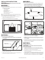
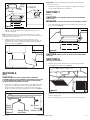
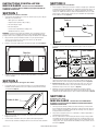
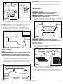
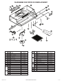
IMPORTANT INSTRUCTIONS OPERATING MANUAL
AV Series
Range Hood
READ AND SAVE THESE INSTRUCTIONS
READ CAREFULLY BEFORE ATTEMPTING TO ASSEMBLE, INSTALL, OPERATE OR MAINTAIN THE PRODUCT DESCRIBED.
PROTECT YOURSELF AND OTHERS BY OBSERVING ALL SAFETY INFORMATION. FAILURE TO COMPLY WITH
INSTRUCTIONS COULD RESULT IN PERSONAL INJURY AND/OR PROPERTY DAMAGE!
RETAIN INSTRUCTIONS FOR FUTURE REFERENCE.
GENERAL SAFETY INFORMATION
When using electrical appliances, basic precautions should always be followed to
reduce the risk of fire, electric shock and injury to person, including the following:
WARNING: TO REDUCE THE RISK OF FIRE, ELECTRIC SHOCK AND
WARNING: TO REDUCE THE RISK OF FIRE, ELECTRIC SHOCK, DO
a) Use this unit only in the manner intended by the manufacturer.If you have
questions, contact the manufacturer.
WARNING: TO REDUCE THE RISK OF A RANGE TOP GREASE FIRE:
INJURY TO PERSON, OBSERVE THE FOLLOWING:
b) Before servicing or cleaning the unit, switch power off at service panel
and lock the service disconnecting means to prevent power from being
switched on accidentally. When the service disconnecting means cannot
be locked, securely fasten a prominent warning device, such as a tag, to
the service panel.
WARNING: TO REDUCE THE RISK OF FIRE, ELECTRIC SHOCK AND
INJURY TO PERSON, OBSERVE THE FOLLOWING:
a) Installation work and electrical wiring must be done by qualified
person(s) in accordance with all applicable codes and standards,
including fire-related construction.
b) Sufficient air is needed for proper combustion and exhausting of gases
through the flue (chimney) of fuel burning equipment to prevent back
drafting. Follow the heating equipment manufacturer’s guideline and
safety standards such as those published by the National Fire Protection
Association (NFPA) and the American Society for Heating, Refrigeration,
and Air Conditioning Engineers (ASHRAE), and the local code authorities.
NOT USE THIS FAN WITH ANY SOLID-STATE SPEED CONTROL DEVICE.
a) Never leave surface units unattended at high settings. Boilovers
cause smoking and greasy spillovers that may ignite. Heat oils
slowly on low or medium settings.
b) Always turn hood ON when cooking at high heat or when flambéing
food (ie. Crepes Suzette, Cherries Jubilee, Peppercorn Beef Flambé).
c) Clean ventilating fans frequently. Grease should not be allowed to
accumulate on fan filter.
d) Use proper pan size. Always use cookware appropriate for the size
of the surface element.
WARNING: TO REDUCE THE RISK OF INJURY TO PERSONS IN THE
EVENT OF A RANGE TOP GREASE FIRE, OBSERVE THE FOLLOWING:
a) SMOTHER FLAMES with a close-fitting lid, cookie sheet, or metal tray,
then turn off burner. BE CAREFUL TO PREVENT BURNS. If the flames do
not go out immediately, EVACUATE AND CALL THE FIRE DEPARTMENT.
b) NEVER PICK UP A FLAMING PAN - You may be burned.
c) When cutting or drilling into wall or ceiling, do not damage electrical
wiring and other hidden utilities.
c) DO NOT USE WATER, including wet dishcloths or towels a violent steam explosion will result.
CAUTION: FOR GENERAL VENTILATING USE ONLY. DO NOT USE TO
d) Use an extinguisher ONLY if:
EXHAUST HAZARDOUS OR EXPLOSIVE MATERIALS AND VAPORS.
I.
You know you have a Class ABC extinguisher, and you already
know how to operate it.
EXHAUST AIR, BE SURE TO DUCT AIR OUTSIDE - DO NOT VENT EXHAUST
AIR INTO SPACES WITHIN WALLS OR CEILINGS OR INTO ATTICS, CRAWL
SPACES, OR GARAGES.
II.
The fire is small and contained in the area where it started.
III. The fire department is being called.
d) Ducted fans must always be vented to the outdoors.
IV. You can fight the fire with your back to an exit.
e) This unit must be grounded.
WARNING: TO REDUCE THE RISK OF FIRE, USE ONLY METAL
CAUTION: TO REDUCE THE RISK OF FIRE AND TO PROPERLY
f) To avoid motor bearing damage and noisy and/or unbalanced impellers,
keep drywall spray, construction dust, etc. off power unit.
DUCTWORK.
g) Read all instructions before installing or using range hood.
SAVE THESE INSTRUCTIONS
6728002 Rev. F 1-11
www.airkinglimited.com
1 of 12
SECTION 3
INSTALLATION INSTRUCTIONS
CAUTION: MAKE SURE POWER IS SWITCHED OFF AT SERVICE PANEL
BEFORE STARTING INSTALLATION.
SECTION 1
Preparing the Range Hood
Prepare the Hood for Installation
1. Choose the type of ducting you will require. This model is equipped to vent either
Vertically or Horizontally through a 3-1/4" x 10" duct. It can be modified to be
ductless (re-circulates the air back into the kitchen) with the addition of a model
RF34 Charcoal Filter (not included) or vented through a 7" round duct with the
addition of a model E-22a or RDC7 Duct Collar (not included) (Figure 3).
1. Unpack hood from the carton and confirm that all pieces are present. In addition to
the range hood you should have:
1 - Aluminum Grease Filter
1 - 3-1/4"x 10" Damper
3 - Damper Mounting Screws
4 - #8 Mounting Screws
1 - Wire Compartment Cover and Screw
1 - Instruction/Safety Sheet
Vertical
Ductless
Horizontal
NOTE: Some hoods may be shipped with a protective plastic adhered to the range
hood. It is recommended to leave this in place during installation to protect the hood
from scratching. Remove when the installation is complete.
2. Lay the hood flat on a table so the underside is facing you. Use a piece of
cardboard to avoid damaging the table or the hood.
Figure 1
3. Remove lamp cover by squeezing the two tabs together (Figure 1):
2a. Horizontal or Vertical - Remove the square knockout by inserting a screw driver
under the edge and break the tabs holding it in place. Peel back with pliers (Figure 4).
Horizontal
Vertical
Ductless
Tabs
Figure 1
Figure 4
4. Install a 60 watt maximum type A19 bulb and reinstall the lamp cover.
SECTION 2
Prepare the location for Hood Support
2b. Ductless - Remove the hood’s front louver cover, exposing the front air slots. To
remove louver slide to one side and lift the trailing edge. Do not use a screwdriver
or any other object that could scratch the hood (Figure 4).
1. If the hood will be installed under cabinets that have a recessed bottom, it will be
necessary to install wood mounting strips (not included) so the hood will mount
properly (Figure 2).
2c. 7" Round - Remove the round knockout located on the top of the hood by inserting
a screw driver under the edge and break the tabs holding it in place. Peel back
with pliers (Figure 4).
3. Determine where the electrical service will enter the hood and remove the appropriate
electrical knockout by inserting a screw driver into the slot and rocking back and forth
until the knockout comes loose (Figure 4).
SECTION 4
Wood Strip
Installing the Range Hood
CAUTION:
MAKE SURE POWER IS SWITCHED OFF AT SERVICE PANEL
BEFORE STARTING INSTALLATION.
1.
Once the proper knockout(s) have been removed, either hold the hood up to the
installation location and mark the locations of the ducting (if applicable), electrical,
and mounting holes or mark the locations by measurement.
2.
Cut appropriate holes for ducting connection (if applicable) and electrical
connection in the wall/cabinet.
3.
For 3-1/4" x 10" vertical or horizontal ducting, install the damper assembly to the hood
by sliding the tabbed section of the damper under the hood body and securing with
the two provided screws. For 7" round ducting, secure either a model E-22A or RCD7
Duct Collar (not included) to the hood with the three provided screws (Figure 5).
Figure 2
2. The thickness of the strips should be the same as the recess of the cabinet and
they should be approximately 2" wide.
3. Install the strips using appropriate length wood screws (not included). Make sure
the strips line up to the keyhole slots of the range hood.
6728002 Rev. F 1-11
www.airkinglimited.com
2 of 12
Hood
Body
Damper
Tab
NOTE: DO NOT disconnect any wiring that has already been crimped with a wire
connector from the factory.
2. Install the wire compartment cover and tighten screw. Make sure all wiring is
securely contained within the wire compartment.
E-22A/RCD7
SECTION 7
Ducting
CAUTION: ALL DUCTING MUST COMPLY WITH LOCAL AND NATIONAL
BUILDING CODES.
WARNING: TO REDUCE THE RISK OF FIRE, USE ONLY METAL DUCTWORK.
1. Connect the ducting to the hood’s duct collar and damper. Secure in place using
tape to seal all joints (Figure 8).
Figure 5
4. Install an approved wire connector to the electrical knockout of the hood and
guide the electrical cable through the hood, allowing at least 6" of wire for
connections and tighten.
NOTE: If installing into existing construction and you will not have access to the
ductwork once the hood is in place, make ducting connections at this point. Refer to
the Ducting Section for instructions.
4. Install the 4 mounting screw at the previously marked locations. Leave
approximately 1/8" clearance. Slide the hood in place through the keyhole slots
and align the front of the hood so that it is flush with the front of the cabinets.
Tighten all screws securely (Figure 6).
Figure 8
1/8"
Keyhole
CAUTION: ALWAYS DUCT THE FAN TO THE OUTSIDE THROUGH A WALL
OR ROOF CAP.
SECTION 8
Finishing the Installation
1. Install the appropriate filter sliding the back side of the filter into the tab and
pressing the front of the filter into place (Figure 9).
Figure 6
SECTION 6
Wiring
CAUTION:
ALL ELECTRICAL CONNECTIONS MUST BE MADE IN
ACCORDANCE WITH LOCAL CODES, ORDINANCES, OR NATIONAL ELECTRICAL CODE.
IF YOU ARE UNFAMILIAR WITH METHODS OF INSTALLING ELECTRICAL WIRING,
SECURE THE SERVICES OF A QUALIFIED ELECTRICIAN.
1. Connect the 2 loose White wires from the range hood to the White wire from the
supply, and the loose Black wire from the range hood to the Black wire of the
supply. Connect the ground wire (green or bare) from the supply to the green
ground screw of the hood. Use approved methods for all connections (Figure 7).
Figure 9
2. Turn switches to the “OFF” position and restore power. Test that the light and the
fan are operating properly.
3. If there is any vibration noise, check for the source and try to tighten fasteners.
Neutral
(White)
from Light
Figure 7
6728002 Rev. F 1-11
Hot (Black)
Neutral (White)
from Motor
Ground
(Green or Bare)
www.airkinglimited.com
3 of 12
SECTION 9
Cleaning
CAUTION:
Operation
Controls
DO NOT USE GASOLINE, BENZINE, THINNER, HARSH
CLEANSERS, ETC., AS THEY MAY DAMAGE THE RANGE HOOD.
Your Range Hood is equipped with two rocker style switches with one controlling
the lighting and the other controlling the exhaust fan. The light switch has two
positions, ON ( I ) and OFF ( II ). The fan is a three position switch, HIGH ( II ), LOW
( I ), and OFF. OFF is the middle position of the switch.
1. Clean your range hood with a mild detergent, such as dishwashing liquid,
and dry with a soft cloth. NEVER USE ANY ABRASIVE PADS OR SCOURING
POWDERS. Completely dry before restoring power. NEVER IMMERSE
ELECTRICAL PARTS IN WATER.
SECTION 10
2. The fan assembly can be vacuumed when build up (dirt, lint, etc.)
accumulates over time. The fan is permanently lubricated and does not
require oiling.
Maintenance
CAUTION:
MAKE SURE POWER IS SWITCHED OFF AT SERVICE PANEL
BEFORE SERVICING THE UNIT.
Filters
Grease Filter - Included with your range hood is an aluminum grease filter
that should be washed in hot water with detergent once a month. Reverse the
instructions in the “Finishing the Installation” section of the instructions to remove
filter. If the grease filter becomes damaged, replace with Air King Model RF35
Grease Filter.
Charcoal Odor Filter - If you have installed an optional combination grease/
charcoal filter, it cannot be washed and must be discarded and replaced when
it becomes noticeably dirty, has stopped filtering the odors, or at least once per
year. Replace with Air King Model RF55 Combination Odor/Grease Filter.
Troubleshooting Guide
Trouble
Probable Cause
1. Hood does not operate when the switch is on.
1a.
A fuse may be blown or a circuit tripped.
1a. Replace fuse or reset circuit breaker.
1b.
Wiring is not connected properly.
1b. Turn off power to unit. Check that all wires are connected.
2. Hood is operating, but air moves slower than normal.
2.
Obstruction in the exhaust ducting.
2.
3. Hood is making a rattling noise.
3a.
Filters are loose.
3a. Turn off power to unit. Check that all filter are securely in place.
3b.
Duct connection is loose.
3b. Turn off power to unit. Check that duct connection is tight.
6728002 Rev. F 1-11
www.airkinglimited.com
Suggested Remedy
Check for any obstructions in the ducting including filter.
4 of 12
LIMITED WARRANTY
WHAT THIS WARRANTY COVERS: This product is warranted against defects in workmanship and/or materials.
HOW LONG THIS WARRANTY LASTS: This warranty extends only to the original purchaser of the product and lasts for one (1) year from the date of original
purchase or until the original purchaser of the product sells or transfers the product, whichever first occurs.
WHAT AIR KING WILL DO: During the warranty period, Air King will, at its sole option, repair or replace any part or parts that prove to be defective or
replace the whole product with the same or comparable model.
WHAT THIS WARRANTY DOES NOT COVER: This warranty does not apply if the product was damaged or failed because of accident, improper handling or
operation, shipping damage, abuse, misuse, unauthorized repairs made or attempted. This warranty does not cover shipping costs for the return of products
to Air King for repair or replacement. Air King will pay return shipping charges from Air King following warranty repairs or replacement
ANY AND ALL WARRANTIES, EXPRESSED OR IMPLIED (INCLUDING, WITHOUT LIMITATION, ANY IMPLIED WARRANTY OF MERCHANTABILITY), LAST
ONE YEAR FROM THE DATE OF ORIGINAL PURCHASE OR UNTIL THE ORIGINAL PURCHASER OF THE PRODUCT SELLS OR TRANSFERS THE PRODUCT,
WHICHEVER FIRST OCCURS AND IN NO EVENT SHALL AIR KING’S LIABILITY UNDER ANY EXPRESS OR IMPLIED WARRANTY INCLUDE (I) INCIDENTAL OR
CONSEQUENTIAL DAMAGES FROM ANY CAUSE WHATSOEVER, OR (II) REPLACMENT OR REPAIR OF ANY HOUSE FUSES, CIRCUIT BREAKERS OR RECEPTACLES.
NOTWITHSTANDING ANYTHING TO THE CONTRARY, IN NO EVENT SHALL AIR KING’S LIABILITY UNDER ANY EXPRESS OR IMPLIED WARRANTY EXCEED
THE PURCHASE PRICE OF THE PRODUCT AND ANY SUCH LIABILITY SHALL TERMINATE UPON THE EXPIRATION OF THE WARRANTY PERIOD.
Some states and provinces do not allow limitations on how long an implied warranty lasts, or the exclusion or limitation of incidental or consequential damages,
so these exclusions or limitations may not apply to you. This warranty gives you specific legal rights. You may also have other rights which vary from state to
state and province to province. Proof of purchase is required before a warranty claim will be accepted.
CUSTOMER SERVICE:
Toll-Free (800) 465-7300
Our Customer Service team is available to assist you with product questions, service center locations, and replacement parts. They can be reached Monday
through Friday, 8am-4pm Eastern. Please have your model number available, as well as the type and style (located on the label inside of your product).
Please do not return product to place of purchase.
www.airkinglimited.com
PARTS FOR DISCONTINUED, OBSOLETE AND CERTAIN OTHER PRODUCTS MAY NOT BE AVAILABLE. DUE TO SAFETY REASONS, MANY ELECTRONIC
COMPONENTS AND MOST HEATER COMPONENTS ARE NOT AVAILABLE TO CONSUMERS FOR INSTALLATION OR REPLACEMENT.
Installer:
Installation Date:
Place of Purchase:
Model Number:
6728002 Rev. F 1-11
www.airkinglimited.com
5 of 12
REPLACEMENT PARTS DIAGRAM
# Qty.
1 1
2 1
3 1
4 2
5 2
6 1
7 1
8 1
9 1
10 1
11 1
12 1
13 1
14 1
1
1
1
15 1
1
1
1
6728002 Rev. F 1-11
Description
Filter RF35
Push Nut
Fan Blade
#8 B Screw
Hex Nut
Motor Bracket
Light Lens
#6 AB Screw
Wire Compartment Cover
Lamp Holder
Bushing
#10 Ground Screw
Jumper Wire
Switch Plate - White
Biscuit
Almond
Black
Motor Switch - White
Biscuit
Almond
Black
Replacement Part #
5S4199011
5S4199001
5S4199002
5S1999015
5S1999006
5S4199003
5S4199004
5S1999004
5S4199005
5S4199006
5S1999016
5S1999002
5S4199007
5S1421003
5S1421004
5S1421005
5S1421006
5S1418003
5S1418004
5S1418005
5S1418006
# Qty.
16 1
1
1
1
17 1
1
1
1
1
18 1
19 1
1
1
1
20 4
21 1
22 1
23 1
www.airkinglimited.com
Description
Light Switch - White
Biscuit
Almond
Black
Wrapper -21"
24"
30"
36"
42"
Motor
Louver Plate - White
Biscuit
Almond
Black
#8 Screw
Damper Frame
Damper
Damper Bumper
Replacement Part #
5S1419003
5S1419004
5S1419005
5S1419006
5S1427010
5S1427020
5S1427030
5S1427040
5S1427050
5S2199001
5S1429003
5S1429004
5S1429005
5S1429006
5S1999017
5S4199013
5S4199014
5S4199015
6 of 12
INSTRUCCIONES IMPORTANTES –
MANUAL DE OPERACIÓN
AV Series
Hotte de cuisinière
LIRE ET CONSERVER CES INSTRUCTIONS
LIRE SOIGNEUSEMENT AVANT DE TENTER D’ASSEMBLER, INSTALLER, OPÉRER OU DE RÉPARER LE PRODUIT DÉCRIT.
PROTÉGEZ VOUS-MÊME ET LES AUTRES EN OBSERVANT TOUTE L’INFORMATION DE SÉCURITÉ. FAILLIR À SE CONFORMER
AUX INSTRUCTIONS PEUT RÉSULTER EN BLESSURE PERSONNELLE GRAVE ET/OU EN DOMMAGE À LA PROPRIÉTÉ.
CONSERVER CES INSTRUCTIONS POUR RÉFÉRENCES FUTURES.
INSTRUCTIONS GÉNÉRALES DE SÉCURITÉ
Lors de l’utilisation d’appareils électriques, des précautions de base doivent
toujours être suivies pour réduire les risques d’incendie, de choc
électrique et de blessures corporelles, incluant ce qui suit:
AVERTISSEMENT : POUR RÉDUIRE LES RISQUES
D’INCENDIE, DE CHOC ÉLECTRIQUE OU DE BLESSURES PERSONNELLES
OBSERVER CE QUI SUIT:
a) Utiliser cette unité seulement de la manière pour laquelle le fabricant l’a
conçu. Si vous aviez des questions, veuillez contacter le fabricant.
b) Avant d’effectuer un service ou de nettoyer l’unité, couper l’alimentation
électrique dans le panneau de distribution et verrouiller le dispositif de
déconnexion afin d’éviter que l’alimentation ne revienne accidentellement.
Lorsque le dispositif ne peut être verrouillé, fixer solidement un avis
d’avertissement, tel qu’une étiquette, au panneau de distribution.
AVERTISSEMENT : POUR RÉDUIRE LES RISQUES
D’INCENDIE, DE CHOC ÉLECTRIQUE OU DE BLESSURES PERSONNELLES
OBSERVER CE QUI SUIT:
a) Le travail d’installation et le câblage électrique doivent être effectués par
une(des) personne(s) qualifiée(s) en conformité avec tous les codes et
normes applicables, incluant la construction relative aux incendies.
b) De l’air en quantité suffisante est requis pour la bonne combustion
et l’évacuation de gaz par le conduit (cheminée) provenant d’équipement de
brûlage au combustible pour prévenir un refoulement. Suivre les directives
du fabricant de l’équipement de chauffage et les normes de sécurité telles
que celles publiées par la National Fire Protection Association (NFPA) et
de la American Society for Heating, Refrigeration, and Air Conditioning
Engineers (ASHRAE), et de celles des autorités locales du code.
c) Lorsque vous coupez ou perforez un mur ou un plafond, prenez garde
de ne pas endommager les fils électriques ou tout appareil qui pourrait
être dissimulé.
AVERTISSEMENT : POUR RÉDUIRE LES RISQUES
D’INCENDIE ET POUR ÉVACUER L’AIR ADÉQUATEMENT, ASSUREZ-VOUS
D’ÉVACUER L’AIR VERS L’EXTÉRIEUR – NE PAS ÉVACUER L’AIR DANS
DES ESPACES DANS LES MURS, LES PLAFONDS OU LES GRENIERS, LES
GALERIES TECHNIQUES OU LES GARAGES.
AVERTISSEMENT : POUR USAGE DE VENTILATION
GÉNÉRALE EXCLUSIVEMENT. NE PAS UTILISER POUR ÉVACUER DU
MATÉRIEL ET DES VAPEURS DANGEREUSES OU EXPLOSIVES.
d) Les ventilateurs avec conduits doivent toujours être évacués vers
l’extérieur.
e) Cette unité doit être mise à la terre.
f) Pour éviter des dommages aux roulements des moteurs et/ou des hélices
bruyantes ou déséquilibrées, empêcher la poussière de cloison sèche,
poussière de construction, etc., d’atteindre l’unité de puissance.
g) Lire toutes les instructions avant d’installer ou d’utiliser la hotte de cuisine.
6728002 Rev. F 1-11
AVERTISSEMENT : POUR RÉDUIRE LES RISQUES
D’INCENDIE OU DE CHOC ÉLECTRIQUE, NE PAS UTILISER CE VENTILATEUR
AVEC UN RÉGULATEUR DE VITESSE ÉLECTRONIQUE.
AVERTISSEMENT : POUR RÉDUIRE LES RISQUES
D’INCENDIE DE GRAISSE SUR LE DESSUS DE LA CUISINIÈRE:
a) Ne jamais laisser les unités de surface à des degrés élevés sans
surveillance. Les débordements par bouillonnement produisent de
la fumée et des débordements graisseux qui peuvent s’enflammer.
Chauffer les huiles lentement à des degrés faibles ou modérés.
b) Toujours mettre la hotte EN MARCHE lors de cuisson à haute
température ou lors de flambage de nourriture (par ex., des Crêpes
Suzette, de Cerises Jubilées, steak flambé, etc.)
c) Nettoyer les ventilateurs d’évacuation fréquemment. Aucune
accumulation de graisse ne devrait être tolérée sur les filtres du
ventilateur.
d) Utiliser des poêlons de taille appropriée. Toujours utiliser les batteries
de cuisine appropriées pour la taille de l’élément de surface.
AVERTISSEMENT : POUR RÉDUIRE LES RISQUES DE
BLESSURES PERSONNELLES DANS L’ÉVENTUALITÉ D’UN FEU DE GRAISSE
SUR LA SURFACE DE CUISSON, SUIVRE LES INDICATIONS SUIVANTES:
a) ÉTOUFFER LES FLAMMES avec un couvercle bien ajusté, une
tôle à biscuits, ou un cabaret de métal, puis, mettre le gril hors
fonction. PRENEZ SOIN D’ÉVITER LES BRÛLURES. Si les flammes ne
s’éteignent pas immédiatement, ÉVACUER ET APPELER LE SERVICE
DES INCENDIES.
b) NE JAMAIS SAISIR UN POÊLON EN FLAMME – vous pourriez être
brûlé.
c) NE PAS UTILISER DE L’EAU, incluant les linges à vaisselle ou les
serviettes mouillées – il en résulterait une violente explosion de vapeur.
d) Utiliser un extincteur SEULEMENT SI:
I. Vous savez que vous avez un extincteur de classe ABC, et que
vous savez déjà comment l’opérer.
II. Le feu est petit et contenu dans la zone où il a commencé.
III. On appelle le service des incendies.
IV. Vous pouvez combattre l’incendie avec une sortie derrière vous.
AVERTISSEMENT : POUR RÉDUIRE LES RISQUES
D’INCENDIE, UTILISER UNIQUEMENT DES CONDUITS EN MÉTAL.
CONSERVER CES INSTRUCTIONS
www.airkinglimited.com
7 of 12
INSTRUCTIONS D’INSTALLATION
MISE EN GARDE : ASSUREZ-VOUS QUE L’ALIMENTATION
ÉLECTRIQUE EST COUPÉE À PARTIR DU PANNEAU DE DISTRIBUTION AVANT DE
COMMENCER L’INSTALLATION.
SECTION 1
Préparation de la hotte de cuisinière
1. Sortez la hotte de l’emballage et assurez-vous d’avoir toutes les pièces. En plus
de la hotte, vous devriez avoir :
1 - Filtre à graisse en aluminium
1 - Clapet de 8,25 x 25,4 cm (3-1/4 po x 10 po)
3 - Vis de montage de clapet
4 - Vis de montage #8
1 - Couvercle du compartiment de câblage et vis
1 - Feuille d’instructions/ sécurité
SECTION 3
Préparez la hotte pour l’installation
1. Choisir le type de conduits qui sera requis. Ce modèle est équipé pour souffler tant
verticalement qu’horizontalement dans un conduit de 8,25 x 25,4 cm (3-1/4 po x 10
po). Il peut être modifié pour devenir sans conduit (recirculation de l’air dans la
cuisine) avec l’addition d’un filtre au charbon modèle RF34 (non inclus) ou soufflé
au travers d’un conduit rond de 17,78 cm (7 po) avec l’addition d’un clapet modèle
E-22a ou RDC7 (non inclus) (Figure 3).
Vertical
Sans Conduit
Horizontal
REMARQUE : Certaines hottes peuvent être expédiées avec un plastique protecteur
collé sur la hotte. Il est recommandé de la laisser en place durant l’installation pour
protéger la hotte contre les égratignures. L’enlever lorsque l’installation sera complétée.
2.
Déposez la hotte à plat sur la table de manière à ce que la partie inférieure
soit face à vous. Placez un morceau de carton en dessous afin d’éviter
d’endommager la table ou la hotte.
3. Enlever le couvercle de lampe en pressant les deux onglets ensemble (Figure 1):
Figure 1
2a. Horizontal ou Vertical - Enlever l’alvéole défonçable en insérant un tournevis sous
le contour et casser les attaches qui le retiennent en place. Peler avec des pinces
(Figure 4).
Horizontal
Attaches
Vertical
Sans Conduit
Figure 3
4. Installer une ampoule de type A19 d’un maximum de 60 watts et réinstaller le
couvercle de lampe.
2b. Sans Conduit - enlever le cache persienne, exposant les fentes à air à l’avant. Pour
enlever les persiennes glisser vers un côté et soulever le flanc arrière. Ne pas
utiliser de tournevis ou autre objet qui pourrait endommager la hotte (Figure 4).
SECTION 2
Préparez l’emplacement du support de la hotte.
1.
Figure 4
Pour installer la hotte sous des armoires dont la base est en retrait, il faut d’abord
installer des bandes de fixation en bois (non comprises) afin que la hotte soit fixée
convenablement (Figure 2).
2c. Rond de 17,78 cm (7 po) - enlever l’alvéole défonçable située sur le dessus de
la hotte en insérant un tournevis sous le rebord et briser les attaches qui la
maintiennent en place. Peler avec des pinces (Figure 4).
3. Déterminer où le service électrique entrera dans la hotte et enlever les alvéoles
défonçables électriques appropriées en insérant un tournevis dans la fente et en en le
repliant vers l’avant et l’arrière jusqu’à ce que les alvéoles deviennent lâches (Figure 4).
SECTION 4
Installation de la hotte
Bande de bois
MISE EN GARDE :
ASSUREZ-VOUS QUE L’ALIMENTATION
ÉLECTRIQUE EST COUPÉE À PARTIR DU PANNEAU DE DISTRIBUTION AVANT DE
COMMENCER L’INSTALLATION.
1. Une fois que la (les) bonne(s) alvéole(s) a(ont) été enlevée(s), au choix, tenir la
hotte à l’emplacement d’installation et marquer les endroits appropriés des trous
pour les conduits (si applicable), l’électricité et de montage ou encore, marquer
les emplacements en les mesurant.
Figure 2
2. L’épaisseur des bandes doit correspondre au retrait de l'armoire et doit avoir une
largeur d'environ 5 cm.
3.
Posez les bandes à l’aide de vis à bois (non comprises) de longueur appropriée.
Assurez-vous que les bandes sont alignées aux encoches en trou de serrure de la hotte.
6728002 Rev. F 1-11
2.
Couper les trous appropriés pour le raccordement des conduits (si applicable) et
électrique dans le mur/ l’armoire.
3.
Pour un conduit vertical ou horizontal de 8,25 x 25,4 cm (3-1/4 po x 10 po), installer
l’assemblage de clapet à la hotte en glissant la section à onglets du clapet sous le
corps de la hotte et en vissant les deux vis fournies. Pour un conduit rond de 17,78
cm (7 po), fixer soit un clapet modèle E-22A ou RCD7 (non inclus) à la hotte avec les
3 vis fournies (Figure 5).
www.airkinglimited.com
8 of 12
Hood
Body
Damper
Tab
REMARQUE : NE PAS déconnecter quelque fil qui ait déjà été serti avec un connecteur
de fil à l’usine.
2. Placez le couvercle du compartiment de fils et serrez la vis. Assurez-vous que
tous les fils sont placés de manière sécuritaire à l’intérieur du compartiment.
E-22A/RCD7
SECTION 7
Conduits
MISE EN GARDE :
TOUS LES CONDUITS DOIVENT ÊTRE
CONFORMES AUX CODES DU BÂTIMENT LOCAUX ET NATIONAUX.
MISE EN GARDE :
POUR RÉDUIRE LES RISQUES D’INCENDIE,
UTILISER UNIQUEMENT DES CONDUITS EN MÉTAL.
Figure 5
4. Install an approved wire connector to the electrical knockout of the hood and
guide the electrical cable through the hood, allowing at least 6" of wire for
connections and tighten.
1. Raccorder les conduits au collet et au clapet de la hotte. Fixer en place en utilisant
du ruban pour canalisations pour sceller tous les joints (Figure 8).
REMARQUE : Si installation dans une construction existante et que vous n’aurez pas
accès aux conduits une fois que la hotte sera en place, faire les raccords des conduits
à ce point. Référez-vous à la section des Conduits pour les instructions.
4. Installer les 4 vis de montage aux endroits marqués précédemment. Laisser un
dégagement d’environ 0,33 cm (1/8 po). Glisser la hotte en place au travers des
trous en poire et aligner le devant de la hotte pour qu’il soit à effleurement avec le
devant des armoires. Visser fermement toutes les vis (Figure 6).
0,32 cm
Encoche
en trou de
serrure
Figure 8
MISE EN GARDE :
TOUJOURS PASSER LES CONDUITS DU
VENTILATEUR VERS L’EXTÉRIEUR EN UTILISANT UN CAPUCHON MURAL OU DE TOIT.
SECTION 8
Finition de l’installation
1. Installer le filtre approprié, en glissant le côté arrière du filtre dans l’onglet et en
pressant l’avant du filtre en place (Figure 6).
Figure 6
SECTION 6
Câblage
MISE EN GARDE :
TOUTES LES CONNEXIONS ÉLECTRIQUES DOIVENT
ÊTRE CONFORMES AUX CODES DU BÂTIMENT LOCAUX, AUX RÈGLEMENTS LOCAUX
OU AU CODE NATIONAL DE L'ÉLECTRICITÉ. SI LES MÉTHODES POUR INSTALLER DES
CÂBLAGES ÉLECTRIQUES NE VOUS SONT PAS FAMILIÈRES, FAITES APPEL AUX SERVICES
D’UN ÉLECTRICIEN QUALIFIÉ.
1. Connecter les deux fils lâches Blancs de la hotte de cuisine au fil Blanc de
l’alimentation, et le fil lâche Noir de la hotte au fil Noir de l’alimentation. Connecter
le fil de mise à la terre (vert ou dénudé) de l’alimentation à la vis verte de mise à la
terre de la hotte. Utiliser des méthodes de connexion approuvées pour toutes les
connexions (Figure 7).
Figure 9
Neutre
(blanc) de
la lumière
Figure 7
6728002 Rev. F 1-11
2.
Mettre les interrupteurs en position « HORS (OFF) » et rétablir l’alimentation. Tester
que la lampe et le ventilateur fonctionnent correctement.
3.
S’il y a un bruit de vibration, recherchez-en la source et essayez de serrer les attaches
ou d’ajuster le ruban pour canalisations pour faire un raccord ou un scellant plus serré.
Chaud (noir)
Neutre (blanc)
de la moteur
Mise à la terre
(vert ou nu)
www.airkinglimited.com
9 of 12
SECTION 9
Nettoyage
MISE EN GARDE :
Opération
Contrôles
Votre Hotte de Cuisine est équipée de deux interrupteurs à type basculant dont
l’un contrôle l’éclairage et l’autre le ventilateur. L’interrupteur de la lampe a deux
positions, EN ( I ) et HORS ( II ). Le ventilateur a un interrupteur à trois positions,
HAUT ( II ), BAS ( I ) et HORS. HORS est la position médiane de l’interrupteur.
SECTION 10
Entretien
MISE EN GARDE : ASSUREZ-VOUS QUE L’ALIMENTATION
N’UTILISEZ PAS D’ESSENCE, DE BENZINE, DE
DILUANT, DE PRODUITS D’ENTRETIEN PUISSANTS, ETC., PUISQU’ILS POURRAIENT
ENDOMMAGER LA HOTTE.
1.
Nettoyez la hotte avec du savon doux, comme du savon à vaisselle liquide, et un
chiffon doux et sec. N'UTILISEZ JAMAIS DE TAMPON ABRASIF OU DE POUDRE
À RÉCURER. Essuyez complètement l’appareil avant de rétablir l’alimentation
électrique. N’IMMERGEZ JAMAIS DE COMPOSANTS ÉLECTRIQUES DANS L’EAU.
2. Vous pouvez nettoyer les dépôts (saletés, peluches, etc.) qui se sont
accumulés dans le ventilateur à l’aide d’un aspirateur. Comme le ventilateur
est continuellement lubrifié, il n’est pas nécessaire de l’huiler.
ÉLECTRIQUE EST COUPÉE À PARTIR DU PANNEAU DE DISTRIBUTION AVANT DE
COMMENCER L’INSTALLATION.
Filtres
Filtre à graisses – Un filtre à graisses en aluminium est inclus avec votre hotte
et il devrait être nettoyé dans l’eau chaude avec du détergent une fois par mois.
Renverser les instructions dans la section «terminer l’installation» des instructions
pour retirer le filtre. Si le filtre à graisses devient endommagé, le remplacer par un
Filtre à graisses modèle RF35 de Air King.
Filtre anti-odeurs au charbon – si vous avez installé un filtre combiné à graisse/
charbon, ils ne peuvent pas être lavés et doivent être jetés lorsqu’ils deviennent
notablement sales, qu’ils aient cessé de filtrer les odeurs, ou au moins une fois par
année. Remplacer avec un Filtre Combiné à Graisse / Odeur Modèle RF55 de Air King.
Guide de dépannage
Trouble
Cause possible
Solution suggérée
1. La hotte ne fonctionne pas lorsque l’interrupteur 1a. Un fusible peut être grillé ou un disjoncteur peut
1a.
est à EN (ON).
être déclenché.
1b. Le câblage n’est pas raccordé correctement.
1b.
2. La hotte fonctionne, mais l’air circule plus
2. Obstruction dans les conduits d’évacuation.
2.
lentement que la normale.
3. La hotte produit un son de crécelle.
3a. Le moteur est lâche.
3a.
3b. Le raccord des conduits est lâche.
3b.
6728002 Rev. F 1-11
www.airkinglimited.com
Remplacer le fusible ou réinitialiser le disjoncteur.
Couper l’alimentation de l’unité. Vérifier que tous les fils sont raccordés.
Vérifier pour quelque obstruction dans les conduits incluant le filtre.
Couper l’alimentation de l’unité. Retirer le filtre, vérifier que toutes les
vis sont serrées complètement.
Couper l’alimentation de l’unité. Vérifier que tous les raccords des
conduits sont bien serrés.
10 of 12
GARANTIE LIMITÉE
CE QUE COUVRE CETTE GARANTIE : Ce produit est garanti contre tout vice de fabrication ou de matière.
COMBIEN DE TEMPS CETTE GARANTIE DURE : Cette garantie se rapporte seulement à l'acheteur original du produit et dure pendant une (1) année de la
date de l'achat original ou jusqu'à ce que l'acheteur original du produit vend ou transfère le produit, celui qui se produit en premier.
QUE FERA AIR KING : Au cours de la période de garantie, Air King, à son choix, réparera ou remplacera n'importe quelle partie ou pièces qui s'avèrent
défectueuses ou remplacera le produit entier par le même modèle ou un modèle comparable.
CE QUE CETTE GARANTIE NE COUVRE PAS : Cette garantie ne s'applique pas si le produit était endommagé ou arrête de fonctionner en raison d’un accident,
d’une mauvaise manipulation ou opération, de dommages d’expédition, d’abus, de mauvaise utilisation, de réparation faite ou tentées non autorisées. Cette
garantie ne couvre pas les coûts d'expédition pour le retour des produits à Air King pour la réparation ou le remplacement. Air King payera les frais d'expédition
de retour de Air King après les réparations ou le remplacement de garantie.
TOUTES LES GARANTIES, EXPRESSES OU TACITES (COMPRENANT, SANS LIMITATION, TOUTE GARANTIE TACITE DE VALEUR MARCHANDE), DURENT UN
AN DE LA DATE DE L'ACHAT ORIGINAL OU JUSQU'À CE QUE L'ACHETEUR ORIGINAL DU PRODUIT VEND OU TRANSFÈRE LE PRODUIT, CELUI QUI SE PRODUIT
EN PREMIER ET DANS AUCUN CAS AIR KING N’ASSUME AUCUNE RESPONSABILITÉ EXPRESSE OU TACITE POUR (I) DES DOMMAGES ACCIDENTELS OU
INDIRECTS DE N’IMPORTE QUELLE CAUSE, OU (II) LE REPLACEMENT OU LA RÉPARATION DE TOUS FUSIBLES, DISJONCTEURS OU RÉCEPTACLES DE MAISON.
MALGRÉ N'IMPORTE QUOI À L'EFFET CONTRAIRE, DANS AUCUN CAS LA RESPONSABILITÉ D’AIR KING, SOUS UNE GARANTIE EXPRESSE OU TACITE, NE
DÉPASSERA LE PRIX D'ACHAT DU PRODUIT ET UNE TELLE RESPONSABILITÉ SE TERMINERA AVEC L'EXPIRATION DE LA PÉRIODE DE GARANTIE.
Certains états et provinces ne permettent pas les limitations de la période de garantie, ou l'exclusion ou la restriction des dommages accidentels ou indirects,
et, par conséquent, les présentes restrictions ne peuvent pas s’appliquer. La présente garantie vous donne des droits légaux spécifiques et peut-être certains
autres droits qui peuvent varier selon la province. La preuve d’achat est exigée avant qu'une réclamation de garantie ne soit acceptée.
SERVICE À LA CLIENTÈLE :
Sans frais (800) 465-7300
Notre équipe de service à la clientèle est disponible pour vous aider avec des questions sur le produit, les adresses des centres de service, et les pièces de
rechange. Vous pouvez la rejoindre, du lundi au vendredi, de 8h:00 à 16h:00 HNE. Veuillez avoir le numéro du modèle disponible, ainsi que le genre et le style
(qui se trouvent sur l'étiquette à l'intérieur de votre produit).
Veuillez ne pas renvoyer le produit à l'endroit de l'achat.
www.airkinglimited.com
IL SE PEUT QUE LES PIÈCES POUR LES PRODUITS DISCONTINUÉS, OBSOLÈTES ET AUTRES PRODUITS NE SOIENT PAS DISPONIBLES. POUR DES RAISONS
DE SÛRETÉ, BEAUCOUP DE COMPOSANTS ÉLECTRONIQUES ET LA PLUPART DES COMPOSANTS DES CHAUFFAGES NE SONT PAS À LA DISPOSITION DES
CONSOMMATEURS POUR L'INSTALLATION OU LE REMPLACEMENT.
Installateur :
Date d’installation :
Lieu de l’achat :
Numéro de modèle :
6728002 Rev. F 1-11
www.airkinglimited.com
11 of 12
DIAGRAMME DES PIÈCES DE REMPLACEMENT
# de pièce
# Qte. Description
de remplacement
1 1 Filtre RF35
5S4199011
2 1 Écrou
5S4199001
3 1 Hélice de ventilateur
5S4199002
4 2 Vis #8 B
5S1999015
5 2 Écrou hexagonal
5S1999006
6 1 Support de moteur
5S4199003
7 1 Lentille de lumière
5S4199004
8 1 Vis #6 AB
5S1999004
9 1 Couvercle de compartiment à câblage
5S4199005
10 1 Support à lampe
5S4199006
11 1 Bague
5S1999016
12 1 Vis #10 de mise à la terre
5S1999002
13 1 Cavalier
5S4199007
14 1 Plaque d’interrupteur - Blanc
5S1421003
1 Biscuit
5S1421004
1 Amande
5S1421005
1 Noir
5S1421006
15 1 Interrupteur du moteur - Blanc
5S1418003
1 Biscuit
5S1418004
1 Amande
5S1418005
1 Noir
5S1418006
6728002 Rev. F 1-11
# de pièce
# Qte. Description
de remplacement
16 1 Interrupteur de lumière - Blanc
5S1419003
1 Biscuit
5S1419004
1 Amande
5S1419005
1 Noir
5S1419006
17 1 Bande de recouvrement -53,34 cm (21 po) 5S1427010
1 60,96 cm (24 po)
5S1427020
1 76,20 cm (30 po)
5S1427030
1 91,44 cm (36 po)
5S1427040
1 106,68 cm (42 po)
5S1427050
18 1 Moteur
5S2199001
19 1 Plaque de persienne - Blanc
5S1429003
1 Biscuit
5S1429004
1 Amande
5S1429005
1 Noir
5S1429006
20 4 Vis #8
5S1999017
21 1 Cadre de clapet
5S4199013
22 1 Clapet
5S4199014
23 1 Amortisseur de clapet
5S4199015
www.airkinglimited.com
12 of 12