1
3-865-349-15(1) DSR-40/40P Digital Videocassette Recorder Operating Instructions page 2GB Before operating the unit, please read this manual thoroughly and retain it for future reference. GB page 2FR Avant la mise en service de cet appareil, prière de lire attentivement ce mode d’emploi que l’on conservera pour toute référence ultérieure. FR Mode d’emploi DSR-40/40P 1999 by Sony Corporation For DSR-40 WARNING To prevent fire or shock hazard, do not expose the unit to rain or moisture. This symbol is intended to alert the user to the presence of uninsulated “dangerous voltage” within the product’s enclosure that may be of sufficient magnitude to constitute a risk of electric shock to persons. This symbol is intended to alert the user to the presence of important operating and maintenance (servicing) instructions in the literature accompanying the appliance. CAUTION You are cautioned that any changes or modifications not expressly approved in this manual could void your authority to operate this equipment. Note This equipment has been tested and found to comply with the limits for a Class B digital device, pursuant to Part 15 of the FCC Rules. These limits are designed to provide reasonable protection against harmful interference in a residential installation. This equipment generates, uses, and can radiate radio frequency energy and, if not installed and used in accordance with the instructions, may cause harmful interference to radio communications. However, there is no guarantee that interference will not occur in a particular installation. If this equipment does cause harmful interference to radio or television reception, which can be determined by turning the equipment off and on, the user is encouraged to try to correct the interference by one or more of the following measures: • Reorient or relocate the receiving antenna. • Increase the separation between the equipment and receiver. • Connect the equipment into an outlet on a circuit different from that to which the receiver is connected. • Consult the dealer or an experienced radio/TV technician for help. 2GB Precautions Safety • Operate the unit only on 120 V AC, 60 Hz . • If anything falls into the cabinet, unplug the unit and have it checked by qualified personnel before operating it any further. • Unplug the unit from the wall outlet if you do not intend to use it for an extended period of time. To disconnect the cord, pull it out by the plug, never by the cord. Installing • Allow adequate air circulation to prevent internal heat buildup. • Do not place the unit on surfaces (rugs, blankets, etc.) or near materials (curtains, draperies) that may block the ventilation slots. • Do not install the unit near heat sources such as radiators or air ducts, or in a place subject to direct sunlight, excessive dust, mechanical vibration or shock. • Do not install the unit in an inclined position. It is designed to be operated in a horizontal position only. • The unit is not designed for portable use. Install it properly on a flat stable place. Placing it on its side or on a surface slanted more than 30 degrees may cause damage. • Keep the unit and cassettes away from equipment with strong magnets, such as microwave ovens or large loudspeakers. • Do not place heavy objects on the unit. • If the unit is brought directly from a cold to a warm location, moisture may condense inside the VCR and cause damage to the video head and tape. When you first install the unit, or when you move it from a cold to a warm location, wait for about one hour before operating the unit. Information Compatible color systems The DSR-40 is designed to record and play back using the NTSC color system. Recording of video sources based on other color systems cannot be guaranteed. Caution Television programs, films, video tapes and other materials may be copyrighted. Unauthorized recording of such material may be contrary to the provisions of the copyright laws. Also, use of this recorder with cable television transmission may require authorization from the cable television transmission and/or program owner. Owner’s record The model number is located at the rear and front of the unit and the serial number on the top. Record the serial number in the space provided below. Refer to these numbers whenever you call upon your Sony dealer regarding this product. Model No. DSR-40 Serial No. ______________________ For the customers in the U.S.A. Declaration of Conformity Trade Name: Model No.: Responsible Party: Address: Telephone No.: SONY DSR-40 Sony Electronics Inc. 1 Sony Drive, Park Ridge, NJ, 07656 USA 201-930-6970 This device complies with Part 15 of the FCC Rules. Operation is subject to the following two conditions: (1) This device may not cause harmful interference, and (2) this device must accept any interference received, including interference that may cause undesired operation. For DSR-40P WARNING To prevent fire or shock hazard, do not expose the unit to rain or moisture. To avoid electrical shock, do not open the cabinet. Refer servicing to qualified personnel only. Precautions Safety • This unit operates on 220 – 240 V AC, 50 Hz. Check that the unit’s operating voltage is identical with your local power supply. • If anything falls into the cabinet, unplug the unit and have it checked by qualified personnel before operating it any further. • The unit is not disconnected from the mains as long as it is connected to the mains outlet, even if the unit itself has been turned off. • Unplug the unit from the wall outlet if you do not intend to use it for an extended period of time. To disconnect the cord, pull it out by the plug, never by the cord. Installing • This unit is equipped with a fan at the rear. Do not insert objects nor touch the fan during operation. • To prevent internal heat buildup, install the unit at least 5 cm away from the wall, and dust the unit periodically. • Do not place the unit on surfaces (rugs, blankets, etc.) or near materials (curtains, draperies) that may block the ventilation slots. • Do not install the unit near heat sources such as radiators or air ducts, or in a place subject to direct sunlight, excessive dust, mechanical vibration or shock. • The unit is not designed for portable use. Install it properly on a flat stable place. Placing it on its side or on a surface slanted more than 30 degrees may cause damage. • Keep the unit and cassettes away from equipment with strong magnets, such as microwave ovens or large loudspeakers. • Do not place heavy objects on the unit. • If the unit is brought directly from a cold to a warm location, moisture may condense inside the VCR and cause damage to the video head and tape. When you first install the unit, or when you move it from a cold to a warm location, wait for one to two hours before operating the unit. Caution Television programmes, films, video tapes and other materials may be copyrighted. Unauthorised recording of such material may be contrary to the provisions of the copyright laws. Also, use of this recorder with cable television transmission may require authorisation from the cable television transmitter and/or programme owner. Compatible colour systems The DSR-40P is designed to record and play back using the PAL colour system. Recording of video sources based on other colour systems cannot be guaranteed. For the customers in Europe This product with the CE marking complies with both the EMC Directive (89/336/EEC) and the Low Voltage Directive (73/23/EEC) issued by the Commission of the European Community. Compliance with these directives implies conformity to the following European standards: • EN60065: Product Safety • EN55103-1: Electromagnetic Interference (Emission) • EN55103-2: Electromagnetic Susceptibility (Immunity) This product is intended for use in the following Electromagnetic Environment(s): E1 (residential), E2 (commercial and light industrial), E3 (urban outdoors) and E4 (controlled EMC environment, ex. TV studio). For the customers in the Netherlands Voor de klanten in Nederland Bij dit product zijn batterijen geleverd. Wanneer deze leeg zijn, moet u ze niet weggooien maar inleveren als KCA. 3GB Table of Contents Chapter 1 Overview Features ............................................................................. 6 Notes on Video Cassettes .................................................... 8 Notes on Recording / Playing.............................................. 9 Location and Function of Parts ..................................... 10 Front Panel ........................................................................ 10 Rear Panel ......................................................................... 14 Chapter 2 Playback and Recording Playback ........................................................................... 16 Connections for Playback.................................................. 16 Settings for Playback ......................................................... 18 Playback Procedure ........................................................... 19 Playback Functions ........................................................... 20 Recording ........................................................................ 23 Connections for Recording................................................ 23 Settings for Recording ....................................................... 25 Recording Procedure ......................................................... 27 Chapter 3 Using the Unit as a Player in an Editing System Notes on Usage in the Editing System ......................... 30 Connections for a Digital Non-linear Editing ................ 32 Connections for a Cut Editing System .......................... 33 Connections for an A/B Roll Editing System ............... 35 Adjusting an Edit Timing ................................................ 40 Adjusting the Sync and Subcarrier Phases .................. 44 Adjusting Signals ............................................................ 47 Chapter 4 Using the Unit as a Recorder in an Editing System 4GB Table of Contents Using the Unit as a Recorder with FXE-100/100P/120/120P ................................. 49 Chapter 5 Menu Settings Changing Menu Settings ................................................ 51 Changing the SET UP MENU Settings ............................. 51 Menu Contents .................................................................. 51 Recommended settings in the SET UP menu .................... 54 Chapter 6 Maintenance and Troubleshooting Alarm Messages .............................................................. 55 Troubleshooting .............................................................. 56 Notes on Use ................................................................... 57 Appendix Specifications .................................................................. 60 Compatibility of DVCAM and DV Format ...................... 62 Glossary ........................................................................... 64 Index ................................................................................. 66 Table of Contents 5GB GB Features Features Chapter 1 Overview The DSR-40/40P is a 1/4-inch digital videocassette recorder that uses the DVCAM digital recording format. This system achieves stable, superb picture quality by digitally processing video signals that are separated into color difference signals and luminance signals (component video). When connected to Sony Edit Station™, the unit serves as part of powerful non-linear editing system1). The unit is equipped with a full-fledged analog interface to support hybrid systems that combine conventional analog equipment with digital equipment. High-quality PCM digital audio The DSR-40/40P’s main features are described below. Playback compatibility with DV format DVCAM Format DVCAM is based on the consumer DV format, which uses the 4:1:1 component digital format (DSR-40) or the 4:2:0 format (DSR-40P), and provides a 1/4-inch digital recording format for professional use. High picture quality, high stability Video signals are separated into color difference signals and luminance signals, which are encoded and compressed to one-fifth size before being recorded to ensure stable and superb picture quality. Because the recording is digital, multi-generation dubbing can be performed with virtually no deterioration of quality. Wide track pitch The recording track pitch is 15 µm, fully 50 percent wider than the DV format’s 10-µm track pitch. Thanks to this feature, the DVCAM format sufficiently meets the reliability and precision requirements of professional editing. PCM recording makes for a wide dynamic range and a high signal-to-noise ratio, thereby enhancing sound quality. There are two recording modes: 2-channel mode (48-kHz sampling and 16-bits linear code), which offers sound quality equivalent to the DAT (Digital Audio Tape) format, or 4-channel mode (32-kHz sampling and 12-bits nonlinear code). A DV cassette recorded on a DV-format VCR can be played back on this unit. (Cassettes recorded in LP mode cannot be played back.) Choice of two cassette sizes The unit can use both standard-size and mini-size DVCAM cassettes. • According to cassette size, it automatically changes the position of the reel drive plate. • The maximum recording/playback times are 184 minutes for standard size cassettes and 40 minutes for mini-size cassettes. Facilities for High-efficiency Editing The unit provides an abundance of functions that enhance editing efficiency and precision. Remote control The unit can be operated by remote control from an editing controller that supports the RS-422A interface or from a SIRCS2)-system remote control unit such as the optional DSRM-10, or DSRM-20. ........................................................................................................................................................................................................ 1) Non-linear editing This is an editing method that uses video and audio signals that have been digitally encoded and recorded on a hard disk as digital data. When compared with conventional (linear) editing methods, non-linear editing offers vastly improved efficiency in editing operations, such as by eliminating tape transport time. 6GB Chapter 1 Overview 2) SIRCS (Sony Integrated Remote Control System) A command protocol to remote control Sony professional videocassette recorders/players. Compact size If you use the optional remote control unit, the unit has a picture search function that allows you to view color picture at playback speeds up to 14 times normal speed (DSR-40) or 17 times normal speed (DSR-40P) in forward and reverse directions. When remote-controlling this unit in shuttle mode from an editing controller or a remote controller, you can search at any speed in the range 0 (still) to 14 times normal (DSR-40) or 17 times normal (DSR-40P) in both directions. You can also search frame-byframe in jog mode. You can also hear playback audio. The unit achieves compact size suitable for using on a demonstration or a bridal. The unit is also equipped with basic functions that are needed for videocassette recorders and players used in professional digital video editing systems. Menu system for functionality and operation settings The unit provides a menu system to make its various functions easier to use and set up its operation conditions. Jog audio function Superimposition function If you use the optional remote control unit, audio can be monitored at various playback speeds when in jog mode. The audio signals are once stored in memory and then played back at the same rate as the search speed. This allows you to use audio playback to find the desired edit points. Other Features Analog output interfaces Time code, operation mode indications, menus, alarm messages, and other text data can be superimposed and output in analog composite video signals. Easy maintenance function The unit’s digital hours meter functions include two kinds of tally operations for head drum usage hours, and tape threading/unthreading times. The tally results can be viewed on the video monitor. The unit comes with analog output interfaces enabling it to be connected to analog video and audio equipment. • Analog video: Include composite video, component video (Y/R–Y/B–Y), and S-video outputs. • Analog audio: The XLR-type (3-pin) analog audio outputs are provided. “Power-on playback” function (in repeat playback mode) You can start playback immediately when the unit turns on. Chapter 1 Overview 7GB Chapter 1 Overview Chapter 1 Overview High-speed search function Features Notes on Video Cassettes Usable cassettes Chapter 1 Overview Use Standard-DVCAM cassettes or Mini-DVCAM cassettes with this VCR. PDV-184ME can record programs for 184 minutes and PDVM40ME can record for 40 minutes. You can get the highest quality pictures with this digital videocassette recorder using DVCAM cassettes. You may not be able to get as good quality with other cassettes. We recommend using DVCAM cassettes so that you can record your one-time events in highest quality. DVCAM cassette Mini DVCAM cassette Cassette memory Cassette memory is an optional feature that is mounted on some Standard DVCAM cassettes and Mini DVCAM cassettes. When you record a program, the recording date and time, and the programs’ position on the tape are stored in the cassette memory so that you can quickly locate the indicates that you can use the cassettes 16 Kbits program later on. of data can be stored on. On this VCR, you can use the cassettes up to 16 Kbits of data can be mounted on. To save a recording To prevent accidental erasure of a recording, slide in the safety switch on the cassette so that the red portion becomes visible. To record on a tape, slide out the switch so that the red portion is hidden. Write protected Write enabled Note , 8GB Chapter 1 Overview , and are trademarks. Checking the tape for slack Paper clip, etc. Reel Notes on Recording / Playing Copyright precautions On recording You cannot record any software having copyright protection signals on this VCR. If you start recording protected video and audio signals, a warning message appears on the monitor screen and the VCR stops recording. On playback When you play back software having copyright protection signals on this VCR, you may not be able to copy it onto other equipment. Limitations caused by the difference in format This VCR can record, play back and edit the tapes recorded in DVCAM format. It can also play back the tapes recorded in DV format (SP mode). However, due to the difference in format, you may not be able to record or edit some tapes affected by recording conditions of the tape (e.g., A tape originally recorded in DV format is dubbed in DVCAM format). For details, refer to “Compatibility of DVCAM and DV format” on page 62. No compensation for contents of the recording Contents of the recording cannot be compensated for if recording or playback is not made due to a malfunction of the VCR, video tape, etc. Note You cannot play back a DVCAM tape recorded in other color systems on this VCR. Chapter 1 Overview 9GB Chapter 1 Overview Using a paper clip or a similar object, turn the reel gently in the direction shown by the arrow. If the reel does not move, there is no slack. Insert the cassette into the cassette compartment, and after about 10 seconds take it out. Location and Function Location and Function of Parts of Parts Front Panel Chapter 1 Overview 6 COUNTER RESET button 1 Cassette compartment 2 Tape transport control section (see page 12) 2 ON/STANDBY switch and ON/STANDBY lamp 7 EJECT button DUP 1 Display section (see page 11) INPUT SELECT 3 PHONES jack COUNTER AUDIO SELECT MONITOR TIMER TC COUNTER CH-1/2 MIX REPEAT OFF TAPE REMAIN CH-3/4 REC REMOTE MENU LOCAL SET 4 PHONE LEVEL control knob 3 Inside of the door (see page 13) 5 AUDIO INPUT LEVEL control knobs 1 Cassette compartment Accepts standard-size or mini-size DVCAM digital videocassettes. When using a mini-size cassette, insert it into the center of the compartment. 4 PHONE LEVEL control knob Controls the volume of the headphones connected to the PHONES jack. For details of usable cassettes, see page 8. 5 AUDIO INPUT LEVEL control knobs When recording, you can use these knobs to set audio input levels for CH-1 (channel 1) and CH-2 (channel 2), respectively. 2 ON/STANDBY switch and ON/STANDBY lamp Press this switch to turn on the power, and the ON/ STANDBY lamp lights in green. Press it again to turn to standby mode, and the lamp lights in red. Note When the REMOTE/LOCAL switch is set to REMOTE, you cannot turn the unit to standby mode. 3 PHONES jack (stereo minijack) Connect stereo headphones for headphone monitoring during recording or playback. The audio signal you want to monitor can be selected with the AUDIO MONITOR selector inside of the door (3). 10GB Chapter 1 Overview 6 COUNTER RESET button Press this button to reset the tape counter in the display window to “0:00:00 (0H00M00S)”. This button does not work when displaying the time code or the remaining time. 7 EJECT button Press this button to eject a cassette. 1 Display section 2 Time counter display 1 Audio level meter HOURS – CH 1/3 CH 2/4 MINUTES TIMER Mini SECONDS NS AUDIO Fs32k Fs48k FRAMES INPUT DV S VIDEO Chapter 1 Overview 0 6 12 24 3 Video input signals indicators 9 Mini indicator 4 NS AUDIO indicator 8 Cassette indicator 5 Audio mode indicators 7 DVCAM indicator 6 TIMER indicator 1 Audio level meter Indicates the recording level during recording or EE mode, and the playback level during playback. When the audio level exceeds 0 dB, the red indicator lights. Note If you play back the tape whose audio was only recorded on channel 2, the audio level meter for CH2/4 may not function. 2 Time counter display Indicates the following: • Time data: count value of the time counter, time code and remaining time. • Alarm messages (see page 55). • Messages for self-diagnosis function (see page 59). 5 Audio mode indicators Indicates the audio mode during playback or recording or while in EE mode. • During playback it indicates the audio mode in which the tape was recorded. • During recording or while in EE mode, it indicates the currently selected audio recording mode. You can select audio recording mode by setting “AUDIO MODE” menu (see page 53). Fs32k: Lights when playing the tapes recorded in 4-channel mode, or recording a tape in 4-channel mode. Fs48k: Lights when playing the tapes recorded in 2-channel mode, or recording a tape in 2-channel mode. Note Notes • For DSR-40P: Time code is set to the non drop frame mode only. • Time code is indicated as follows: Drop frame: “00:00.00:00” (DSR-40 only) Non drop frame: “00:00:00:00” 3 Video input signals indicators Indicates the currently selected video input signals. INPUT VIDEO, INPUT S VIDEO, or INPUT DV lights. 4 NS (Non Standard) AUDIO indicator Lights when the VCR plays back a tape whose audio recording was made in the unlock mode, or when unlock mode signals are input through the DV jack. When recording in 4-channel mode on this VCR, audio signals are recorded only in channels 1/2. 6 TIMER indicator Lights when setting the TIMER switch to REPEAT. 7 DVCAM indicator Lights except playing back the DV-formatted tapes. 8 Cassette indicator Lights when inserting a digital video cassette available for this VCR. It flashes when ejecting a cassette. 9 Mini indicator Lights when inserting mini-size digital video cassette. For details of unlock mode, see page 62. Chapter 1 Overview 11GB Location and Function of Parts 2 Tape transport control section Note Chapter 1 Overview When the tape reaches to its beginning or its end by rewinding or fast-forwarding, the unit turns to playback pause mode. Then, the playback pause mode is released after the time which is set at “STILL TIMER” menu (See page 52). 2 DUP button 1 Tape Transport indicators DUP DUP STOP REW PLAY F FWD PAUSE REC 3 REC button 4 PAUSE button 5 F FWD button 6 PLAY button 7 REW button 8 STOP button 1 Tape Transport indicators 2 DUP (duplicate) button Use this button to make a work tape having the same time codes as the source tape. For details on duplication, see page 28. 3 REC (record) button When you press the PLAY button while holding down this button, the indicator lights and recording begins. To set the VCR to recording pause mode, press the PAUSE button while holding down this button. 4 PAUSE button When you press this button, the indicator lights, and the VCR is set to pause mode. 5 F FWD (fast forward) button When you press this button, the indicator lights and the tape is fast forwarded. During fast forward, the picture does not appear on the monitor (you can see the picture of the EE mode during fast forward). To search forward, hold this button down during fast forward. 12GB Chapter 1 Overview 6 PLAY button When you press this button, the indicator lights and playback begins. If you press this button while holding down the REW button during stop, the tape is rewound to its beginning and starts playing automatically (during rewind, the REW indicator lights and the PLAY indicator flashes). 7 REW (rewind) button When you press this button, the indicator lights and the tape starts rewinding. During rewind, the picture does not appear on the monitor (you can see the picture of the EE mode during rewind). To search backward, hold this button down during rewind. If you press the PLAY button while holding down this button during stop, the tape is rewound to its beginning and starts playing automatically (during rewind, the REW indicator lights and the PLAY indicator flashes). 8 STOP button Press this button to stop the current tape transport operation. 3 Inside of the door 6 REMOTE/LOCAL switch 7 MENU button Chapter 1 Overview 8 SET button 9 Arrow (˘ ≥) buttons AUDIO COUNTER MONITOR SELECT TIMER CH-1/2 TC REPEAT MIX COUNTER OFF CH-3/4 TAPE REMAIN CL INPUT SELECT REMOTE MENU LOCAL SET 5 TIMER switch 4 AUDIO MONITOR selector 3 COUNTER SELECT selector 2 CL button 1 INPUT SELECT button 1 INPUT SELECT button Selects input signals. Each press of this button cycles through three video signal selection options: video, Svideo, and DV input. When you select one of these options, the corresponding indicator in the display lights up. 2 CL (Clear) button Press this button to make the unit to the state of reconnecting the AC power cord. When you press this button, the setting in the menu is not initialized. 3 COUNTER SELECT selector Select the type of time data in the time counter display. TC: Time code COUNTER: Count value of the time counter TAPE REMAIN: Remaining time 4 AUDIO MONITOR selector Use to select the audio track you want to hear when playing back a tape recorded in 4-channel mode (Fs32k). CH-1/2: Channels 1/2 only MIX: Channels 1/2 and channels 3/4 (mix) CH-3/4: Channels 3/4 only 5 TIMER switch Use to select Auto Repeat using an external AC timer (not supplied). REPEAT: When the power is supplied to this VCR, a tape rewinds to its beginning automatically and playback starts. The VCR repeats the playback from the beginning to the first index (if there is no index on the tape, to the unrecorded portion; if no unrecorded portion, to the tape end). Auto repeat also functions if you set this switch to REPEAT during playback. OFF: Auto Repeat is released. 6 REMOTE/LOCAL switch Selects whether the unit is operated from its front panel or from external (remote) equipment. REMOTE : The unit is operated from an editing controller connected to the REMOTE connector. Available tape transport buttons (on the front panel or optional remote control unit) are set in the menu. LOCAL : The unit is operated from its front panel, or from a SIRCS-system remote control unit connected to the CONTROL S jack. Chapter 1 Overview 13GB Location and Function of Parts 7 MENU button Press this button to display the menu on the monitor screen. Press it again to return from the menu display to the usual display. 8 SET button Press this button to save selected menu items to the unit’s memory. Chapter 1 Overview 9 Arrow (J j) buttons Use these buttons to move around the menu items. Note If you set the REMOTE/LOCAL switch to REMOTE while the menu display is on the monitor, it returns to the usual display. On how to use the menu, see Chapter 5 “Menu Settings”. Rear Panel 4 REF. VIDEO INPUT connector 5 CONTROL S jack INPUT OUTPUT REF.VIDEO INPUT CONTROL S DV VIDEO REMOTE RS-422A 6 REMOTE connector S VIDEO IN/OUT Y R-Y B-Y AC IN 7 DV jack VIDEO CH-1 CH-1/3 CH-2 CH-2/4 AUDIO CH-1/3 AUDIO CH-2/4 8 AC IN connector AUDIO MONITOR 3 OUTPUT connectors 2 MONITOR connectors 1 INPUT connectors 1 INPUT connectors Input video and audio signals. To connect a VCR equipped with the S-video output jack, use the S VIDEO jack on this VCR. 2 MONITOR connectors Output video and audio signals for monitoring. 14GB Chapter 1 Overview 3 OUTPUT connectors Output video and audio signals. To connect a VCR equipped with the S-video input jack, use the S VIDEO jack on this VCR. To connect a VCR equipped with the component input connectors, use the Y, R–Y, B–Y connectors on this VCR. Note on EE mode When the S-video, video, or DV signal is input, this VCR cannot output component signals. You can only output the component signal during normal playback. Chapter 1 Overview 4 REF. VIDEO INPUT connector (BNC-type) Input a reference video (black burst) signal. 5 CONTROL S jack When controlling this VCR from an optional remote control unit such as the DSRM-10/20 (not supplied), connect the unit to this jack. Note SIRCS-system has the same function as CONTROL S-system. 6 REMOTE connector (D-sub 9-pin) Connect an editing controller with the RS-422A interface for remote-control of this VCR. 7 DV jack The DV jack is i.LINK compatible. Use when the equipment connected to the VCR has a DV jack. If you connect the VCR and the other equipment using DV jacks, you can minimize deterioration of picture quality during dubbing, or capturing still pictures by digital processing. For details, refer to the instruction manual of the equipment you use. Note is a trademark of Sony Corporation and indicates that this product is in agreement with IEEE1394-1995 specifications and their revisions. 8 AC IN connector Connect to an AC power outlet using the supplied power cord. Chapter 1 Overview 15GB Playback Playback This section describes the necessary connections, settings and operations to perform playback on this unit. The same settings and operations apply whether you are using the unit as part of an editing system, for dubbing, or as a stand-alone videocassette player. Connections for Playback To digital video equipment with the DV jack Chapter 2 Playback and Recording The video and audio signals are sent with hardly any degradation, enabling high-quality recording. The signal flow is automatically detected so you need not make separate connections for input and output. Recorder Monitor This VCR (Player) to the DV jack DV IN/OUT i.LINK cable (DV connecting cable) (not supplied) L: Signal flow Notes • The external lock function of this unit only supports the standard sync signals. With the DV connection, select the DV input with the INPUT SELECT button on this VCR to prevent malfunction resulting from noise, etc. • Set DV EE OUT in the menu to OFF (see page 52). • With the DV connection, the sound is recorded in the same audio recording mode as that of the source tape. • With the DV connection, tape information (recording date, camcorder data, etc.) recorded on the source tape is transmitted from this VCR (player). 16GB Chapter 2 Playback and Recording Chapter 2 Playback and Recording Chapter 2 Playback and Recording To video equipment without the DV jack Recorder Monitor to the S-video input jack This VCR (Player) INPUT OUTPUT REF.VIDEO INPUT VIDEO S VIDEO Y to the video input jack to the audio input jacks R-Y B-Y VIDEO CH-1 CH-1/3 CH-2 CH-2/4 AUDIO CH-1/3 AUDIO CH-2/4 AUDIO MONITOR to the video input jacks S-video cable (not supplied) 75 Ω coaxial cable (not supplied) XLR cable (not supplied) Video cable (3BNCy3BNC) (not supplied) L: Signal flow Notes • When you connect output jacks of the recorder to input jacks of this VCR, select the input correctly to prevent a humming noise. • Distorted signals (e.g., when played back at a speed other than normal) will not be recorded properly. • The indications (Time code, alarm messages, and menu, etc.) displayed on the monitor screen are output only via the MONITOR connector. • If the DV input is selected, you cannot perform the playback synchronized with the video reference (black burst) signal. Chapter 2 Playback and Recording 17GB Playback Settings for Playback Preparation on the player (this VCR) 1 Power on the video monitor, then set the monitor’s input according to the input signals from the recorder. 2 Set up the recorder. For details, see “Preparation on the recorder” below. Chapter 2 Playback and Recording 3 Power on this unit by pressing the ON/STANDBY switch. The ON/STANDBY lamp lights in green. 4 When you play back a tape recorded in 4-channel mode (Fs 32k), set the AUDIO MONITOR selector to MIX (see page 13). Then select the precise balance between the tracks with the AUDIO MIX BALANCE in the menu (see page 53). Notes • With the DV connection, the playback VCR’s AUDIO MONITOR (sound selection) and AUDIO MIX BALANCE (audio balance adjustment) do not function on the source audio output through the DV jack. • You cannot change the input signal selection during playback or playback pause mode. Preparation on the recorder • Insert a tape for recording. • Select the video and audio input signals to be recorded. Note Editing is not possible with a tape that is copyright protected. 18GB Chapter 2 Playback and Recording Playback Procedure Notes • When controlling this unit from an editing controller connected to the REMOTE connector, set the REMOTE/LOCAL switch to REMOTE. When not, set it to LOCAL. • Do not insert the cassette forcibly. The VCR may be damaged. 1 For details on checking the tape for slack, see page 9. Mini size Insert the mini-size cassette into the center of the cassette compartment. Standard size Tape window facing upward The cassette is automatically drawn into the unit. 2 Press PLAY. This starts the playback operation. Chapter 2 Playback and Recording 19GB Chapter 2 Playback and Recording After checking the tape for slack, hold the cassette so that the tape window is facing upward, then insert it into this unit as illustrated below. Playback Playback Functions You can enjoy various playback functions using the optional remote control unit. For details, refer to the operating instructions supplied with the remote control unit. Playing at various speeds (JOG) You can play at various speeds, or frame by frame. Chapter 2 Playback and Recording Searching (SHUTTLE) You can easily locate the desired scene, and you can quickly and accurately determine edit points. Searching using the index function (DSRM-20 only) Three kinds of search are available on this VCR: – Searching for the beginnings of recordings: Index search – Searching for a point on the tape where the recorded date changes: Date search – Searching for scenes recorded in the photo mode with a digital camcorder: Photo search Note When S-video or video input is selected and no signal is input in search mode, the search screen becomes noisy. In such cases, input the signal or select DV input. For a description of search operations via external equipment, see the equipment’s operating instructions. Displaying tape information (DSRM-20 only) If you record on a tape using a Sony digital camcorder DSR-200/200P/ 200A/200AP/PD100/PD100P, camcorder data (the shutter speed, program AE mode, white balance, iris and gain) can be recorded on the tape. You can check these data during playback on this VCR. 20GB Chapter 2 Playback and Recording Auto Repeat This VCR can repeat the playback of all, or a part of the tape. 1 Set the TIMER switch on the front panel to REPEAT. The TIMER indicator on the front panel lights. 2 3 Press REW to rewind the tape to its beginning. Press PLAY. Auto Repeat using an external AC timer If you connect an external AC timer (not supplied) to this VCR, you can repeat playback automatically at the preset time. 1 Connect an external AC timer (not supplied) to this VCR. This VCR AC timer to a wall outlet 2 Set the TIMER switch on the front panel to REPEAT. The TIMER indicator in the display window lights. 3 Set the start time using the external AC timer. At the preset time, the power turns on, and Auto Repeat playback starts automatically within one minute. The VCR repeats the playback from the beginning to the first index (if there is no index on the tape, to the unrecorded portion; if no unrecorded portion, to the tape end). Chapter 2 Playback and Recording 21GB Chapter 2 Playback and Recording Playback starts. The VCR repeats the playback from the beginning to the first index (if there is no index on the tape, to the unrecorded portion; if no unrecorded portion, to the tape end). Playback Notes • The VCR cannot search for an index or unrecorded portion within 20 seconds from the beginning of the tape. • While a tape is running, do not turn off the power using an AC timer. The VCR and a tape may be damaged. When turning off the power of the VCR, make sure to press the STOP button on this VCR first to stop the tape transport, then turn off the power. To stop Auto Repeat Press the STOP button. Chapter 2 Playback and Recording To release Auto Repeat mode Set the TIMER switch to OFF. 22GB Chapter 2 Playback and Recording Recording This section describes the necessary connections, settings and operations to perform recording on this unit. The same settings and operations apply whether you are using the unit as part of an editing system, for dubbing, or as a stand-alone recorder. Connections for Recording To digital video equipment with the DV jack Player Monitor This VCR (Recorder) to the DV jack DV IN/OUT i.LINK cable (DV connecting cable) (not supplied) l: Signal flow Notes • With the DV connection, the sound is recorded in the same audio recording mode as that of the source tape. To record in a different audio recording mode from the source tape, use the INPUT connectors instead. • With the DV connection, tape information (recording date, camcorder data, etc.) recorded on the source tape is transmitted from the other VCR (player). As a result, when you play back a recorded tape and press the DATA CODE button on the optional DSRM-20 remote control unit, the same tape information recorded on the source tape is displayed on the monitor screen. However, contents of the cassette memory are not transmitted. In addition, the time code is newly recorded on the tape on this VCR, except when copying a tape in Duplication mode. Chapter 2 Recording and Playback 23GB Chapter 2 Playback and Recording The video and audio signals are sent with hardly any degradation, enabling high-quality recording. The signal flow is automatically detected so you need not make separate connections for input and output. Recording To video equipment without the DV jack Monitor Player Chapter 2 Playback and Recording to the S-video output jack This VCR (Recorder) INPUT OUTPUT REF.VIDEO INPUT VIDEO S VIDEO Y to the video output jack to the audio output jacks R-Y B-Y VIDEO CH-1 CH-1/3 AUDIO CH-1/3 AUDIO CH-2/4 AUDIO CH-2 CH-2/4 MONITOR S-video cable (not supplied) 75 Ω coaxial cable (not supplied) Audio cable (not supplied) l: Signal flow Notes • When recording the analog input signals, this VCR can digitally output the signals from the DV jack for backup. Set DV EE OUT in the menu to ON (see page 52). • When you connect output jacks of this VCR to input jacks of the player, select the input correctly to prevent a humming noise. • Distorted signals (e.g., when played back at a speed other than normal) will not be recorded properly. • The indications (Time code, alarm messages, and menu, etc.) displayed on the monitor screen are output only via the MONITOR connector. 24GB Chapter 2 Recording and Playback Settings for Recording Preparation on the recorder (this VCR) Notes 1 Power on the video monitor, then set the monitor’s input according to the input signals from this unit. 2 Set up the player to play back a tape. For details, see “Preparation on the player” on the next page. 3 Power on this unit by pressing ON/STANDBY switch. The ON/STANDBY lamp lights in green. 4 5 Use the COUNTER SELECT selector to select the type of time data to be used. Type of time data Set the selector to Time code TC Count value of the time counter COUNTER Select the video and audio input signals to be recorded. Press INPUT SELECT to select the desired signal. Each press of this button cycles through three signal selection options: video, S-video, and DV input. Each selection is shown by a lit indicator in the display window. Note Once you have started recording, you cannot change the input signal selection (except during recording pause mode). Chapter 2 Recording and Playback 25GB Chapter 2 Playback and Recording • Before recording, set the clock on the VCR so that the recording time can be written into the index signal. You can set the clock by setting the CLOCK SET menu (see page 53). • When controlling this unit from an editing controller connected to the REMOTE connector, set the REMOTE/LOCAL switch to REMOTE. When not, set it to LOCAL. • Editing is not possible with a tape that is copyright protected. Recording 6 When using the line connections (INPUT connectors), select the audio mode. Select the desired mode by setting the AUDIO MODE menu. Audio mode Set the menu to 2-channel mode Fs48k 4-channel mode Fs32k On how to use the menu, see Chapter 5 “Menu Settings”. Notes Chapter 2 Playback and Recording • In the DVCAM format, there are two audio recording modes, with either two channels at 48 kHz or four channels at 32 kHz. It is not possible to select other modes (for example with four channels at 48 kHz). • When recording in 4-channel mode on this VCR, audio signals are recorded only in channels 1/2. • Once you have started recording, you cannot change the audio mode selection. 7 Use the AUDIO INPUT LEVEL control knobs to adjust audio input levels. Watching the audio level meter (see page 11), adjust the level so that the meter does not indicate higher values than 0 dB when the audio signal is at its maximum. When the level exceeds 0 dB, sound distortion occurs. Note With the DV connection, the recorder VCR’s AUDIO MODE (sound selection) and AUDIO INPUT LEVEL (audio balance adjustment) do not function. Preparation on the player • Insert a source tape. • If the player VCR has an EDIT switch, set it to ON. • Turn off the on-screen display. Note With the DV connection, the playback VCR’s AUDIO MONITOR (sound selection) and AUDIO MIX BALANCE (audio balance adjustment) do not function on the source audio output through the DV jack. 26GB Chapter 2 Recording and Playback Recording Procedure 1 After checking that the cassette’s safety switch is set to write enabled position and the tape for slack, hold the cassette so that the tape window is facing upward, then insert it into this unit. For details of the cassette’s safety switch, see page 8. For details of checking the tape for slack, see page 9. 2 Press the playback button on the player. This starts the player’s playback operation. 3 Press and hold REC on this VCR, and press PLAY. This starts the recorder’s recording operation. To stop recording Press the STOP button. Chapter 2 Recording and Playback 27GB Chapter 2 Playback and Recording The cassette is automatically drawn into the unit and the tape is wound round the head drum. The tape is stationary while the head drum rotates. Recording Duplication If you copy a source tape, using the DUP (duplicate) button on this VCR, you can copy the time code recorded on the source tape as they are. You can easily make a work tape having the same time codes as the source tape. The duplicate function on this VCR works only when using a source tape recorded in DVCAM format and making DV connections. Chapter 2 Playback and Recording 1 Connect this VCR and the other (playback) VCR, using an i.LINK cable (DV connecting cable) (not supplied) and select DV with the INPUT SELECT selector on this VCR. 2 3 4 Locate the points where you want to start playback and recording. Press STOP on this VCR to stop the tape transport operation. Press and hold DUP on this VCR, and press PLAY. The DUP indicator flashes and this VCR enters duplicate-standby mode. Notes • If the other (playback) VCR has already started playback, the DUP indicator lights and duplication starts immediately. • If the other (playback) VCR is in the playback pause mode, duplication starts immediately and this VCR continues to record a still picture and a certain time code. 5 Press the play button on the other VCR to start playback. The DUP indicator on this VCR lights and duplicate starts. To adjust the point where duplication starts In step 4 above, press and hold the DUP button instead of the PLAY button, and press the PAUSE button. This VCR remains recording standby mode until you press the PAUSE button again. After the other VCR starts playback, press the PAUSE button at the point where you want to start duplication. To stop duplication Press the STOP button. 28GB Chapter 2 Recording and Playback Notes Chapter 2 Recording and Playback 29GB Chapter 2 Playback and Recording • During duplication, do not change the speed of the player’s tape or set it to pause mode. Otherwise, the time code of the recorded tape becomes out of sequence and you cannot use it for editing. • During duplication, time counter does not appear. Check it in the other (player) VCR. • When you start duplicating, the first part of the source tape may be dropped on the copied tape. Play back the source tape from the preceding point. You cannot completely copy the tape if the source tape is recorded from its beginning point. • You may not be able to copy the first part or an unrecorded portion of the source tape. Locate the recorded portion on the source tape, then start copying. • The recording does not stop the moment you press the STOP button to stop editing. The source picture may be recorded a little longer than you expected. • If you duplicate a tape by using two DSR-40/40Ps, set DV EE OUT in the menu of the player to OFF (see page 52). • The index signals are not recorded when the duplication starts. • If you set the REMOTE/LOCAL switch to REMOTE during duplication, the tape stops. Notes on Usage in the Editing System If you use the unit in an editing system, the following functions are limited. Chapter 3 Using the Unit as a Player in an Editing System Notes on general • Component signals are only output during playback or when selecting DV input. This unit cannot be used as a converter from analog input to component output. • This unit is not equipped with the synchronization function. Adjust the edit timing with the editing controller, and set sync grade to Preroll & Play. • Pause mode will be released after the chosen time in the menu to protect the tape except when using the unit in an editing system. • When the TIMER switch is set to REPEAT, and the tape reaches to its end point by fast-forwarding, the jog dial control is not available from external equipment connected to the REMOTE connector. • You cannot change input signal selection during playback or playback pause mode. • When S-video or video input is selected and no signal is input in search mode, the search screen becomes unstable. • When the tape reaches to its beginning or end using the REW or F FWD button, the unit turns to playback pause mode at the point in a few preceding seconds from its beginning or end. Notes on connection • When you use this unit as a recorder of a system with the FXE-120 whose version is 1.0, this unit cannot be used in the drop frame system. If you want to use it in the drop frame system, upgrade the FXE-120 to version 1.01 (Only for DSR-40). • When inputting a composite or S-video signal, a composite or S-video output signal in EE mode is a through signal of the input. •When inputting a composite or S-video signal, a component signal in EE mode is not output. Component output is only available during playback or when selecting DV input. • If the unit turns off when AUTO OFF has been set to OFF, the operations cannot be available with equipment connected to the REMOTE connector. Turn on the power again and perform the operation. • When inputting a DV signal, and outputting a composite or S-video signal in EE mode, only the color burst signal is exchanged. • When inputting a DV signal, the unit does not perform a playback synchronized with the external sync signal. This playback is only available when selecting S-video or video input. Notes on editing • With the DV connection, the editing accuracy is less than analog editing accuracy. • This unit is not equipped with the first edit function. • Since this unit does not support CTL, the time code of the recorded tape becomes out of sequence and you cannot use it for editing. In such case, adjust the editing IN point. 30GB Chapter 3 Using the Unit as a Player in an Editing System Chapter Using the Unit as a Player in an Editing System Chapter 3 Using the Unit as a Player in3 an Editing System Settings on editing control unit When connecting an editing control unit, make the setting as follows, according to the model. FXE-100/120 Set the VCR device constants as follows: 1 2 3 4 5 6 80 30 00 96 05 05 7 8 9 0A 8A 0A 10 11 12 13 14 15 08 FE 00 80 5A FF 10 11 12 13 14 08 FE 00 80 5A FF 10 11 12 13 14 09 FE 00 80 5A FF 10 11 12 13 14 09 FE 00 80 5A FF FXE-100P/120P Set the VCR device constants as follows: 1 2 3 4 5 6 81 30 00 7D 05 05 7 8 9 0A 8A 0A 15 BVE-600 (NTSC model) Set the VCR device constants as follows: 1 2 3 4 5 6 80 30 00 96 05 05 7 8 9 0A 8A 0A 15 BVE-600 (PAL model) Set the VCR device constants as follows: 1 2 3 4 5 6 81 30 00 7D 05 05 7 8 9 0A 8A 0A 15 RM-450/450CE Set the DIP switches as follows: Left switch 7 6 5 4 3 2 1 0 OFF – – OFF – – – – Right switch (RM-450) 7 6 5 4 3 2 1 0 OFF – OFF ON OFF OFF ON ON Right switch (RM-450CE) 7 6 5 4 3 2 1 0 ON – OFF ON OFF OFF ON ON If the edit timing is out of adjustment, change the setting of the numbers 0 to 2 of the right switch. Chapter 3 Using the Unit as a Player in an Editing System 31GB Connections for a Digital Non-linear Editing The unit can be connected to an ES-3 EditStation to configure a digital non-linear editing system. You can transfer video, audio, time code, and other compressed data from this unit to the ES-3. The unit can transfer index pictures recorded on tape and ClipLink log data stored in cassette memory to the ES-3 in an instant. The following figure shows a connection diagram for non-linear editing system in which this unit serves as the player. For connections of the ES-3 and its peripheral devices, refer to the ES-3 instruction manual. DSR-40/40P REF. VIDEO INPUT 1 B B OUT Chapter 3 Using the Unit as a Player in an Editing System ES-3 EditStation DV 3 MONITOR AUDIO 2 Audio input DV IN/OUT MONITOR VIDEO 1 Composite video input 1 75 Ω coaxial cable (not supplied) 2 Cable with RCA phono plugs (not supplied) Video monitor 3 i.LINK cable (DV connecting cable) (not supplied) Setting of DSR-40/40P 32GB Chapter 3 Switch Setting REMOTE/LOCAL LOCAL Using the Unit as a Player in an Editing System Connections for a Cut Editing System The following figure shows a cut editing system configuration that uses this unit as the player and a DSR-85/85P as the recorder. For details of connecting devices other than the DSR-40/40Ps, refer to the instruction manual of each device. Notes • When S-video or composite input is selected, S-video or composite output is a through signal. • The preroll time of the setting on the RM-450/450CE is required for more than five seconds. • Set RS-422 CUE-UP MODE to WITH VIDEO in the DSR-40/40P’s SET UP menu for improving the editing accuracy. REF. VIDEO OUT 1 REF. VIDEO OUT AUDIO CH-1/3 OUTPUT 4 AUDIO CH-1 IN AUDIO CH-2/4 OUTPUT 4 AUDIO CH-2 IN VIDEO OUTPUT 1 VIDEO IN Y, R-Y, B-Y OUTPUT 1 Y, R-Y, B-Y IN REF. VIDEO INPUT REMOTE 2 MONITOR AUDIO 3 Audio input DSR-85/85P (recorder) 1 REF. VIDEO IN 1 MONITOR AUDIO MONITOR VIDEO 3 1 Composite video input Audio input VIDEO REMOTE OUT 2 (SUPER) 1 Composite video input 2 Source video monitor PLAYER REF. VIDEO IN RM-450/450CE Editing control unit When you select assemble or insert editing mode on the editing controller, the EDIT MODE indicator lights on the front panel of the recorder and the recorder automatically enters the selected editing mode. Main video monitor RECORDER 1 75 Ω coaxial cable (not supplied) 2 9-pin remote control cable (not supplied) 3 Cable with RCA phono plugs (not supplied) 4 Cable with XLR connectors (not supplied) Chapter 3 Using the Unit as a Player in an Editing System 33GB Chapter 3 Using the Unit as a Player in an Editing System DSR-40/40P (player) REF. VIDEO OUT Video signal generator Connections for a Cut Editing System Settings on editing controller For details on the settings of the editing controller, refer to “Adjusting an Edit Timing” on page 40. Settings on the DSR-40/40P (player) and DSR-85/85P (recorder) Switch recorder player REMOTE/LOCAL REMOTE REMOTE For details, refer to the instruction manual of DSR-85/85P. About reference video signals Chapter 3 Using the Unit as a Player in an Editing System In order to provide stable video and audio signals for analog editing, it is necessary for the built-in time base corrector (TBC) to operate correctly. To ensure this, input a reference video signal synchronized with the video signal to the REF. VIDEO INPUT (IN) connector. 34GB Chapter 3 Using the Unit as a Player in an Editing System Connections for an A/B Roll Editing System The following is an example configuration of A/B roll editing system using the DSR-40/40P and DSR-85/85P. In this configuration, the DSR-40/40P is used as player 1, the UVW-1600/ 1600P (an analog Betacam videocassette player) as player 2, and the DSR85/85P as recorder. To create a final tape (a tape that contains a completely packaged program) in Betacam format, you can use a Betacam VCR such as the UVW-1800/1800P as the recorder. The purpose of the following figure is to clearly indicate the flow of signals among the component devices in this system. The specific connections and DSR-85/85P (recorder) settings for this system are described on the following pages. DSR-40/40P (player 1) DUP INPUT SELECT COUNTER AUDIO SELECT MONITOR TIMER CH-1/2 MIX REPEAT OFF TAPE REMAIN CH-3/4 REC REMOTE Chapter 3 Using the Unit as a Player in an Editing System TC COUNTER Video signal generator (Tektronix TSG-130A/131A, etc.) DFS-500/500P DME Switcher MENU LOCAL SET Main video monitor PVE-500, etc. (Editing controller) UVW-1600/ 1600P (player 2) MXP-290 Audio Mixer DSR-85/85P (recorder) DPS-D7 or other delay unita) Source video monitor Audio monitor system Video signal Audio signal Reference video signal Control signal a) When using a DFS-500/500P DME Switcher, the phase of the video signals processed by the DFS500/500P is delayed, which means that a delay unit must be connected between the MXP-290 Audio Mixer’s output and the audio input in the DSR-85/85P (recorder). Note Use the recorder equipped with the synchronization function. Chapter 3 Using the Unit as a Player in an Editing System 35GB Connections for an A/B Roll Editing System Audio monitor system connections The following shows an example of audio monitor system connections. For details of these connections, refer to each connected device’s instruction manual. Speaker (right channel) Audio amplifier Speaker (left channel) Cables with RCA phono plugs (not supplied) MONITOR MONITOR OUT 1 OUT 2 MXP-290 Audio Mixer L R L R Chapter 3 Using the Unit as a Player in an Editing System Reference video signal connection When you perform recording or editing, be sure to use a reference video signal. For details of the reference video signals, see “About reference video signals” on page 34. REF. VIDEO IN 75 Ω termination switch: ON REF. VIDEO IN DFS-500/500P DME Switcher PVE-500 Editing Control Unit DSR-85/85P (recorder) 4 3 2 1 REF. VIDEO IN REF. VIDEO IN 75 Ω termination switch: ON REF. VIDEO IN 75 Ω termination switch: ON UVW-1600/1600P (player 2) BLACK BURST OUT REF. VIDEO INPUT DSR-40/40P (player 1) REF. VIDEO IN Use 75 Ω coaxial cables for all of these connections. 36GB Chapter 3 Using the Unit as a Player in an Editing System Control signal connections The following shows an example of control signal connections to enable the editing controller to control all other A/B roll editing system devices. Setting on all devices controlled from the editing controller Switch Setting REMOTE/LOCAL REMOTE Mixer control mode selection switch: PARALLEL DSR-40/40P (player 1) 9-pin remote control cablea) PLAYER 1 MIXER Chapter 3 Using the Unit as a Player in an Editing System PVE-500 Editing Control Unit REMOTE a) 9-pin remote control cable PLAYER 2 9-pin remote control cablea) RECORDER SWITCHER 9-pin remote control cablea) 9-piny15-pin mixer control cable (not supplied) EDITOR (15-pin) MXP-290 Audio Mixer EDITOR DFS-500/500P DME Switcher REMOTE DSR-85/85P (recorder) REMOTE UVW-1600/1600P (player 2) a) Use an optional RCC-5G/10G/30G 9-pin remote control cable. Chapter 3 Using the Unit as a Player in an Editing System 37GB Connections for an A/B Roll Editing System Video/audio signal connections The following shows an example of video/audio signal connections in an A/B roll editing system. In this example, analog component signals are used as the video signals and XLR 3-pin connectors are used as audio input/output connectors. COMPONENT VIDEO IN (Y, R–Y, B–Y) 1 VIDEO INPUTS COMPONENT 2 DSR-85/85P (recorder) DFS-500/500P DME Switcher PGM OUT COMPONENT 1 Chapter 3 Using the Unit as a Player in an Editing System AUDIO IN CH-1 3 CH-2 3 CH-1 OUT CH-2 OUT DPS-D7 or other delay unit CH-1 IN 3 LINE OUT 2 1 VIDEO INPUTS COMPONENT 1 2 DSR-40/40P (player 1) COMPONENT VIDEO Y, R–Y, B–Y OUT CH-2 IN 3 LINE OUT 1 MXP-290 Audio Mixer MIC/LINE 4 3 2 1 3 IN 3 3 3 AUDIO OUT CH-1 CH-2 COMPONENT 1 OUTPUT UVW-1600/1600P (player 2) 1 12-piny3×BNC cable (not supplied) (Consult your Sony dealer about this cable.) 2 12-pin dubbing cable (not supplied) AUDIO OUTPUT CH-1 CH-2 3 Cable with XLR connectors (not supplied) Switch Settings on the DSR-85/85P (recorder) Setting AUDIO IN 600 Ω ON/OFF ON AUDIO IN –6 dBu/0 dBu/+4 dBu Normally +4 dBu For details of the video/audio input and audio mode settings, refer to the instruction manuals for the devices used. 38GB Chapter 3 Using the Unit as a Player in an Editing System Connection of a video monitor Set up the following connections to enable monitoring of video and audio signals on a video monitor. In addition to video signals, you can have time data, the DSR-40/40P’s operation mode, alarm messages, and other information displayed as text on the monitor screen. Video monitor DSR-40/40P 75 Ω termination switch: ON (or attach a 75 Ω terminator) Input switches: Set according to the type of input signals. Audio input 1 MONITOR AUDIO Chapter 3 Using the Unit as a Player in an Editing System Composite video input MONITOR VIDEO 2 1 Cable with RCA phono plugs (not supplied) 2 75 Ω coaxial cable (not supplied) Note When you want to monitor the edited tape, use the monitor output connector on a recording VCR. Chapter 3 Using the Unit as a Player in an Editing System 39GB Adjusting an Edit Timing Using this unit as a player with the RM-450/450CE 1 2 Set the SYNCHRO selector to ON. Set the number 3 of the SYSTEM PRESET right switch to OFF (it is set to OFF at factory). Setting this to OFF adjusts the synchronization of the recorder. 3 Execute the LEARN function. Using this unit as a player 1 with the PVE-500 When using this unit as the player 2, the menu item is indicated in ( ). Chapter 3 Using the Unit as a Player in an Editing System 1 2 Set Sync Edit of SEtUP-10 to OFF in the SETUP menu. 3 4 Set rEC Sync of SEtUP-15 to On in the SETUP menu. 5 Execute the LEARN function. Set P1 dELAY (P2 dELAY) of SEtUP-13 (SEtUP-14) to LEArn in the SETUP menu. Set P1 Sync (P2 Sync) of SEtUP-16 (SEtUP-17) to OFF in the SETUP menu. Using this unit as a player 1 with the FXE-120/120P • When using this unit as the player 2, the menu item is indicated in ( ). • When using the FXE-100/100P that has been upgraded with the FXEKIT1, the menu item is indicated in [ ]. 1 Display the item 104 [301] SYNC GRADE in the SETUP menu, and set PLAYER1 (PLAYER2) to PREROLL & PLAY. 2 Display the item 301 (302) [401 as player 1, 402 as player 2] DEVICE TYPE PLAYER1 (DEVICE TYPE PLAYER2) in the SETUP menu, and set the VCR device constants. 3 Execute the LEARN function. If the edit timing is out of adjustment, follow “Adjusting the IN point” on the next page. 40GB Chapter 3 Using the Unit as a Player in an Editing System Adjusting the IN point If the actual edited point does not accurately coincide with the preset editing point, perform the fine adjustment of the edit timing using the SETUP menu of the editing control unit. This improves the editing accuracy. 1 Display the item 301 (302) [401 as player 1, 402 as player 2] DEVICE TYPE PLAYER1 (DEVICE TYPE PLAYER2) in the SETUP menu, and set it from DISABLE to ENABLE. 2 Repeat editing several times and check the shift of the editing point; that is, count the number of frames to be adjusted. Note The editing result may differ between DISABLE and ENABLE settings of SETUP menu item 301 (302) [401 as player 1, 402 as player 2]. Be sure to check the editing result after changing the setting to ENABLE. Set the SETUP menu item 301 (302) [401 as player 1, 402 as player 2] from BYTE 01 to BYTE 10, and calculate the adjustment value. How to calculate the adjustment value If the actual IN point shifts forward to the IN point preset on the player IN point OUT point Preset editing points Adjustment value Actual editing points OUT point IN point 08 (default setting) + number of frames obtained in step 2 Example: To adjust 5 frames 08 + 05 = 0D Adjustment value is calculated in hexadecimal. If the actual IN point shifts backward to the IN point preset on the player IN point OUT point Preset editing points Adjustment value Actual editing points IN point OUT point 08 (default setting) – number of frames obtained in step 2 Example: To adjust 5 frames 08 – 05 = 03 (Continued) Chapter 3 Using the Unit as a Player in an Editing System 41GB Chapter 3 Using the Unit as a Player in an Editing System 3 Adjusting an Edit Timing 4 Perform a trial editing and confirm the adjustment result. Repeat steps 3 and 4 until best possible result is obtained. Using this unit as a recorder with FXE-120/120P • When using this unit as a recorder, also see chapter 4 “Using the Unit as a Recorder in an Editing System.” • When using FXE-100/100P that has been upgraded with FXE-KIT1, the menu item is indicated in [ ]. Chapter 3 Using the Unit as a Player in an Editing System 1 Display the item 102 [112] REMOTE INTERFACE in the SETUP menu, and set RECORDER to OTHERS. 2 Display the item 104 [301] SYNC GRADE in the SETUP menu, and set RECORDER to PREROLL & PLAY. 3 Display the item 303 [403] DEVICE TYPE RECORDER in the SETUP menu, and set the VCR device constants. 4 Execute the LEARN function. If the edit timing is out of adjustment, follow “Adjusting the IN point” below. Adjusting the IN point If the actual edited point does not accurately coincide with the preset editing point, perform the fine adjustment of the edit timing using the SETUP menu of the editing control unit. This improves the editing accuracy. 1 Display the item 303 [403] DEVICE TYPE RECORDER in the SETUP menu, and set it from DISABLE to ENABLE. 2 Repeat editing several times and check the shift of the editing point; that is, count the number of frames to be adjusted. Note The editing result may differ between DISABLE and ENABLE settings of SETUP menu item 303 [403]. Be sure to check the editing result after changing the setting to ENABLE. 3 42GB Chapter 3 Set the SETUP menu item 303 [403] from BYTE 01 to BYTE 10, and calculate the adjustment value. Using the Unit as a Player in an Editing System How to calculate the adjustment value If the actual IN point shifts forward to the IN point preset on the player IN point OUT point Player VCR Adjustment value Recorder VCR IN point OUT point 08 (default setting) – number of frames obtained in step 2 Example: To adjust 5 frames 08 – 05 = 03 If the actual IN point shifts backward to the IN point preset on the player Chapter 3 Using the Unit as a Player in an Editing System IN point OUT point Player VCR Adjustment value Recorder VCR IN point OUT point 08 (default setting) + number of frames obtained in step 2 Example: To adjust 5 frames 08 + 05 = 0D Adjustment value is calculated in hexadecimal. 4 Perform a trial editing and confirm the adjustment result. Repeat steps 3 and 4 until best possible result is obtained. Using this unit as a player with the BVE-600 1 Set the sync grade (menu 2) to mode number 4, PREROLL & PLAY in auxiliary mode. 2 Set the VCR device constants in the setting mode. Chapter 3 Using the Unit as a Player in an Editing System 43GB Adjusting the Sync and Subcarrier Phases When using two or more players, as in an A/B roll editing system, phase synchronization of the signals (i.e. system sync) is necessary and for composite signals only, the subcarrier phase must also be in sync. If not, picture instabilities or color break-up may occur at edit points. After configuring the editing system, use a vectorscope to adjust the sync and subcarrier phase of the recorder and players. Subcarrier phase adjustment is necessary when using composite signals or Y/C signals. DSR-40/40P (player 1) DUP Switcher INPUT SELECT COUNTER AUDIO SELECT MONITOR TIMER TC COUNTER CH-1/2 MIX REPEAT OFF TAPE REMAIN CH-3/4 REC REMOTE MENU LOCAL SET DSR-85/85P (recorder) Chapter 3 Using the Unit as a Player in an Editing System BLACK BURST OUT UVW-1600/1600P (player 2) PGM OUT 75 Ω coaxial cable (B) A IN 75 Ω coaxial cable (A) Vectorscope (Tektronix 1750/1751, etc.) B IN REF. VIDEO EXT IN PVE-500 Editing control unit Note Ensure that the 75 Ω coaxial cables (A) and (B) are of the same length. Note Note The sync and subcarrier phase of the output signal from the DFS-500/ DFS-500P Switcher are automatically adjusted. 44GB Chapter 3 Using the Unit as a Player in an Editing System Performing a phase adjustment operation 1 Press the SCH button on the vectorscope. The vectorscope switches to “SCH” mode. 2 Press the B channel button on the vectorscope. This displays the black burst signal from the switcher. 3 Press the EXT button on the vectorscope. This switches the vectorscope to external synchronization mode. 4 Adjust the phase synchronization control on the vectorscope so that the sync and subcarrier phases are close to the reference line. Chapter 3 Using the Unit as a Player in an Editing System Sync phase Subcarrier phase Reference line Align the sync and subcarrier phase of the black burst signal to the reference line. 5 6 Output the player 1 signal from the switcher, using the PVE-500. Press the A channel button on the vectorscope. This displays the sync phase and subcarrier phase (composite signals only) of the signal from player 1. 7 On player 1, adjust the SYNC control, using the H PHASE COARSE menu for rough adjustment and the H PHASE FINE menu for fine adjustment, so that the output from player 1 on channel (A) is in correct phase alignment with the black burst signal on channel (B) (See page 53). (Continued) Chapter 3 Using the Unit as a Player in an Editing System 45GB Adjusting the Sync and Subcarrier Phases 8 On player 1, adjust the SC control, using the SC 0/180 menu for rough adjustment and the SC PHASE menu for fine adjustment, so that the output from player 1 on channel (A) is in correct phase alignment with the black burst signal on channel (B) (See page 53). This indicator moves as you adjust the H PHASE COARSE or H PHASE FINE menu. This indicator moves as you adjust the SC 0/180 or SC PHASE menu. Adjust the sync and subcarrier phase of the output signal from player 1. Chapter 3 Using the Unit as a Player in an Editing System Note When component signals are used, the subcarrier phase indicator does not appear. 9 Output the player 2 signal from the switcher, using the PVE-500, and repeat steps 7 and 8 to adjust the sync and subcarrier phase of the output from player 2. Adjust the signals 46GB Chapter 3 Using the Unit as a Player in an Editing System Adjusting Signals You can adjust each signal level of the component output signal and the chrominance signal gain level of the composite signal. Connect the reference video (black burst) signal one-to-one with a device that generates the reference video signal, or make a loop-through connection. If the device has a terminal switch, terminate the connection properly. Both a waveform monitor and a vectorscope are required for adjustments. Note If you adjust component signal level, be sure to adjust chrominance signals gain level of composite signals. Video signal generator DSR-40/40P REF. VIDEO INPUT EXT REF IN Y, R-Y, B-Y OUTPUT Component input Waveform monitor Composite video input VIDEO OUT Composite video output Vectorscope Composite video input Adjusting component signal level 1 Play back the DSR-40/40P, and output the signals from the Y, R–Y, and B–Y connectors of the OUTPUT connectors. The picture is displayed on the waveform monitor. 2 Adjust Y signal level at the PB COMPONENT Y LEVEL menu (See page 53). 3 Adjust R–Y signal level at the PB COMPONENT R–Y LEVEL menu (See page 53). 4 Adjust B–Y signal level at the PB COMPONENT B–Y LEVEL menu (See page 53). Chapter 3 Using the Unit as a Player in an Editing System 47GB Chapter 3 Using the Unit as a Player in an Editing System EXT REF IN Adjusting Signals Adjusting chrominance signal gain level of the composite signal 1 Play back the DSR-40/40P, and output the signals from the VIDEO connector of the OUTPUT connector. The picture is displayed on the vectorscope. 2 Adjust R–Y signal gain level at the COMPOSITE R–Y GAIN menu (See page 53). 3 Adjust B–Y signal gain level at the COMPOSITE B–Y GAIN menu (See page 53). Chapter 3 Using the Unit as a Player in an Editing System 48GB Chapter 3 Using the Unit as a Player in an Editing System Using the Unit as a Recorder with FXE-100/100P/120/120P Notes When using this unit as a recorder: • You cannot execute video/audio insert editing. • When you use the unit as a recorder with the FXE-120/120P, only assemble editing is available. • Adjust the edit timing (See page 40). • Set RECORDER MODE to FXE RECORDER. • When you use the unit as a recorder with the FXE-100/100P, the FXEKIT1 is required for upgrading the FXE-100/100P. • Editing accuracy is not guaranteed. If the duration is very short, the recording may not function properly. • Be sure to execute the LEARN function. If you do not use the unit for a long time, you have to execute the function also. • If you execute REC command via RS-422A, it delays the recording start time for about five minutes. • Set RECORDER to OTHERS in the SETUP menu item 102 (112: when using the FXE-100/100P that has been upgraded with the FXE-KIT1) REMOTE INTERFACE of the FXE-120/120P. When using this unit as a recorder with the FXE-100/100P (that has been upgraded with the FXE-KIT1) DSR-200A/200AP Audio output LANC RS-422 IF-FXE2 Audio/Video DSR-40/40P output Video output DUP RS-422 INPUT SELECT COUNTER AUDIO SELECT MONITOR TIMER TC COUNTER CH-1/2 MIX REPEAT OFF TAPE REMAIN CH-3/4 REC REMOTE MENU LOCAL Video input Audio input Video input Audio input FXE-100/100P + FXE-KIT1 Chapter 4 Audio input Video input Ref. input Video output RS-422 Audio output RS-422 Ref. Input RS-422 B.B. output Player Audio/video input SET RS-422 PGM video output PGM audio output Using the Unit as a Recorder in an Editing System 49GB 4 Using the Unit as a Recorder in an Editing System Using the Unit as a Recorder in anChapter Editing System For details on usage and connections, refer to the operating manuals supplied with your devices used in a system. Chapter 4 This unit can be used as a recorder with the FXE-100/100P/120/120P. However, editing accuracy will not correspond with the RS-422A standard in the editing system. Using the Unit as a Recorder with FXE-100/100P/120/120P When using this unit as a recorder with the FXE-120/120P LANC DSR-200A/200AP Audio output Video output Audio/Video output DSR-40/40P RS-422 DUP Video input Audio input REPEAT OFF CH-3/4 REC Chapter 4 Using the Unit as a Recorder in an Editing System 50GB Chapter 4 Using the Unit as a Recorder in an Editing System REMOTE MENU LOCAL PGM audio output Audio/ input PGM video output FXE-120/120P Video input Audio input TIMER CH-1/2 MIX TAPE REMAIN Video input Ref. input Video output LANC Ref. Input RS-422 Audio output B.B. output Player COUNTER AUDIO SELECT MONITOR TC COUNTER SET RS-422 RS-422 Audio/video input INPUT SELECT Changing Menu Settings Changing the SET UP MENU Settings Follow the instructions below to change the settings. 1 Press MENU. Chapter 5 Menu Settings This VCR has various functions available, and you can set and check them on the monitor screen. Before operation, set the clock by setting the CLOCK SET menu. You can change the menu settings on the SET UP MENU screen. If necessary, change the settings manually. The SET UP MENU appears on the monitor screen. SET UP MENU LOCAL ENABLE RS-422 CUE UP MODE AUTO OFF AUTO REWIND INDEX WRITE CASSETTE MEMORY SEARCH CASSETTE MEMORY ERASE SELECT 2 & SET END MENU Press ˘/≥ to select the option you want to change, and press SET. Each menu option appears on the monitor screen (see the table below). 3 Press ˘/≥ to change the setting, and press SET. The menu disappears from the monitor screen. To cancel the menu settings, press MENU again. Chapter 3 Menu Settings Menu Contents Initial settings are indicated in bold letters. Menu options Set this option to LOCAL ENABLE ALL DISABLE STOP & EJECT EJECT RS-422 CUE-UP MODE WITH VIDEO WITHOUT VIDEO Description of settings • When the REMOTE/LOCAL switch is set to REMOTE, all of the tape transport control buttons (front panel/remote control unit) are disabled. • When the REMOTE/LOCAL switch is set to REMOTE, only the STOP and EJECT buttons (front panel/remote control unit) are enabled. • When the REMOTE/LOCAL switch is set to REMOTE, only the EJECT button (front panel) is enabled. • While searching with equipment connected to the REMOTE connector, the searching picture is displayed. • Does not display the searching picture. (The searching speed will be faster than when set to WITH VIDEO.) Chapter 5 Menu Settings 51GB Menu Organization Menu options Set this option to AUTO OFF ON OFF AUTO REWIND ON Description of settings • To turn off the VCR automatically if there is no operation and the tape stops for an hour (Auto Off). • To deactivate Auto Off. OFF • To rewind the tape to its beginning automatically if the tape reaches to an end (Auto Rewind). • To deactivate Auto Rewind. INDEX WRITE AUTO OFF • To record index signals when recording begins. • Not to record index signals. CASSETTE MEMORY SEARCH AUTO • To search recordings with the cassette memory. If the tape does not have a cassette memory, the VCR will search recordings using index signals recorded on the tape itself. • To search recordings using the index signals recorded on the tape. OFF CASSETTE MEMORY ERASE ALL DATA INDEX DATA DATE DATA PHOTO DATA FIELD PHOTO PB FRAME • To erase all the data in the cassette memory. (When using the cassette whose memory can store over 16 Kbits of data, you can only select ALL DATA.) • To erase index data in the cassette memory. • To erase date data in the cassette memory. • To erase photo data in the cassette memory. • To prevent the picture from blurring when playing a tape recorded in photo mode. • To see a clear picture when playing a still picture. Note When selecting FRAME, a picture recorded in photo mode may be blurred. Chapter 5 Menu Settings DV EE OUT ON OFF • To output the selected line input signals from the DV jack. • To output only playback video and audio signals from the DV jack. DISPLAY POSITION CENTER LOWER RIGHT OFF • To display the tape counter in the center of the monitor screen. • To display the tape counter in the lower right of the monitor screen. • Not to display the tape counter. CAUTION DISPLAY ON OFF • To display alarm messages on the monitor screen. • Not to display alarm messages. BEEP ON OFF TIME CODE (DSR-40 only) AUTO • To output a beep sound when an illogical operation is made. • To deactivate the beep. • To set the time code to the same one as already recorded on the tape. • To set the time code to Non Drop Frame. • To set the time code to Drop Frame. Note If you use AUTO and start recording at the beginning of the tape, the time code is set to Non Drop Frame. NDF DF PREROLL TIME SELECT 3SEC 5SEC 7SEC 10SEC The preroll time can be set between 3 and 10 seconds by four steps. When an editing controller such as the PVE-500 has been connected, this setting is disabled and the editing controller’s setting is in effect. The preroll time setting is also performed on the editing controller. AFTER CUE-UP STOP • After a cue-up, the unit informs the editing unit that it is in stop mode. (The unit is actually in still mode.) • After a cue-up, the unit turns to still mode. STILL Playback still delay can be set between 0 and 9 frames by 11 steps. You can set the delay which the unit turns to playback mode from still mode. PB STILL DELAY 0FRAME – 10FRAME RECORDER MODE NORMAL PLAYER • To use the unit as a normal player. FXE RECORDER • To use the unit as a recorder with the FXE-120/120P in a system. You can set the time which releases still or pause mode to protect the 8SEC – 4MIN tape. Select time from 6 settings ranging from 8 seconds to 4 minutes. STILL TIMER 52GB Chapter 5 Menu Settings Description of settings Menu options Set this option to NEXT MODE FROM STILL STEP FWD • To advance the tape one frame after elapsing the set time of STILL TIMER during still mode. STB OFF • To turn the unit to standby-off mode from still mode after elapsing the set time of STILL TIMER. H PHASE COARSEa) — For rough adjustment of sync phase. b) H PHASE FINEa) — For fine adjustment of sync phase. b) SC 0/180 0DEG 180DEG For rough adjustment of subcarrier phase. b) SC PHASEa) — For fine adjustment of subcarrier phase. b) PB COMPONENT Y LEVELa) — Adjusts Y signal level of the component signal in the playback mode. b) a) PB COMPONENT B–Y LEVELa) — a) Adjusts B–Y signal level of the component signal in the playback mode. b) PB COMPONENT R–Y LEVEL — Adjusts R–Y signal level of the component signal in the playback mode. b) COMPOSITE B–Y GAINa) — Adjusts B–Y signal gain level of the composite signal in the playback mode. b) a) — Adjusts R–Y signal gain level of the composite signal in the playback mode. b) AUDIO MIX BALANCE — If you set the AUDIO MONITOR selector to MIX, you can select the precise balance between channels 1/2 and channels 3/4 by five steps. AUDIO MODE Fs48k • To set the audio mode to 2-channel mode (16bit mode). This mode uses the whole audio area to record one stereo track. You can get higher sound quality. Fs32k • To set the audio mode to 4-channel mode (12bit mode). This mode separates the audio area into 2 parts. You can record two kinds of audio, stereo 1 and stereo 2. When recording on this VCR, audio signals are recorded only in channels 1/2. ON OFF • To listen to the sound when playing a tape at various speeds. • To turn off the sound when playing a tape at various speeds. COMPOSITE R–Y GAIN JOG WITH SOUND HOURS METER DRUM ROTATION THREADING — Set the clock on this VCR so that the recording time can be written into the index signal. Using ˘/≥ and SET buttons, set the date and time. a) The z mark appears on the monitor screen when the value is set to “0.” b) Adjust the value with the J/j buttons. Chapter 5 Menu Settings 53GB Chapter 3 Menu Settings CLOCK SET The digital hours meter keeps cumulative counts of the head drum rotation time and the number of unthreading operations. These counts can be displayed on the monitor screen and are unresettable. • The cumulative total hours of drum rotation with tape threaded is displayed in 10-hour increments. • The cumulative number of tape unthreading operation is displayed in 10-operation increments. Menu Organization Recommended settings in the SET UP menu Depending on the position of the REMOTE/LOCAL switch, set the menu options as follows: Chapter 5 Menu Settings Menu options Default REMOTE LOCAL LOCAL ENABLE ALL DISABLE Default Default RS-422 CUE-UP MODE WITH VIDEO Default Default AUTO OFF OFF OFF ON AUTO REWIND ON OFF ON INDEX WRITE AUTO Default Default CASSETTE MEMORY SEARCH AUTO Default Default CASSETTE MEMORY ERASE ALL DATA Default Default PHOTO PB FIELD Default Default DV EE OUT OFF Default Default DISPLAY POSITION LOWER RIGHT Default Default CAUTION DISPLAY ON Default Default BEEP ON Default Default TIME CODE (Only for DSR-40) AUTO Default Default PREROLL TIME SELECT 7 SEC Default Default AFTER CUE-UP STOP Depending on editing unit Default PB STILL DELAY 0 FRAME Default Default RECORDER MODE NORMAL PLAYER Depending on editing unit Default STILL TIMER 8 SEC 4 MIN Default NEXT MODE FROM STILL STB OFF STEP FWD Default H PHASE COARSE – Depending on editing system Default H PHASE FINE – Depending on editing system Default SC 0/180 0 DEG Depending on editing system Default SC PHASE – Depending on editing system Default PB COMPONENT Y LEVEL – Depending on editing system Default PB COMPONENT B-Y LEVEL – Depending on editing system Default PB COMPONENT R-Y LEVEL – Depending on editing system Default COMPOSITE B-Y GAIN – Depending on editing system Default COMPOSITE R-Y GAIN – Depending on editing system Default AUDIO MIX BALANCE – Default Default AUDIO MODE Fs48k Default Default JOG WITH SOUND ON ON OFF • Default: Set the menu option to be suitable for your usage; you can use with the default setting. • Depending on editing unit: Set the menu option to be suitable for your unit. • Depending on editing system: Set the menu option to be suitable for your system. 54GB Chapter 5 Menu Settings Alarm Messages Message Meaning / Remedy PLEASE CONFIRM THE SAFETY SWITCH OF THE CASSETTE Check that the protect tab is slid in so that the red portion visible. n Slide back the safety switch (see page 8). NO CASSETTE MEMORY You try to erase cassette memory when there is no cassette memory. VCR IS RECORDING You press a certain operation button during recording or editing. PLEASE INSERT A NEW CASSETTE Though no cassette is inserted in the cassette compartment, you press PLAY, etc. n Insert a cassette. THE TAPE IS REWOUND You press REW at the beginning of the tape. PLEASE REWIND OR INSERT A NEW CASSETTE You try to start playback or recording at the tape end. n Rewind the tape or insert a new cassette. PLEASE SET THE CLOCK When turning on the power, the clock has not been set. n Set the clock in the menu (see page 53). THIS PROGRAM IS COPYRIGHT PROTECTED You try to dub the tape on which copyright protect signals are recorded. CASSETTE MEMORY IS TOO LARGE TO ERASE You try to erase data on a tape having more than 16 Kbits memory capacity in INDEX DATA, DATE DATA, or PHOTO DATA mode. n Erase it in ALL DATA mode (see page 52). WRITING ON CASSETTE MEMORY. PLEASE WAIT You do certain operation while the VCR is writing on cassette memory. n Operate after writing on cassette memory is complete. VCR IS IN DUP MODE You press a certain operation button during duplication. Chapter 6 Maintenance and Troubleshooting Various messages appear on the monitor screen (“Err” appears in the display window). Check them with the following list. Chapter 6 Maintenance and Troubleshooting Chapter 6 Maintenance and Troubleshooting 55GB Troubleshooting Symptom Cause / Remedy The power cannot be turned on. The power plug is disconnected. n Connect the plug. The unit will not operate even if the power has been turned on. • The REMOTE/LOCAL switch is set to REMOTE. n Set it to LOCAL (See page 13). • Moisture condensation occurs. t Turn off the power and disconnect the power plug. After about one minute, connect the plug and turn on the power. t Wait for about one hour with the power turned on. • The cassette is not inserted straight. t Insert it straight. The unit cannot be controlled using buttons on the unit. The REMOTE/LOCAL switch is set to REMOTE. n Set it to LOCAL (See page 13). The cassette cannot be ejected. The REMOTE/LOCAL switch is set to REMOTE. n Set it to LOCAL (See page 13). The cassette cannot be inserted, or it is ejected promptly. • There is moisture condensation on the head drum. n Wait for about an hour. • The cassette is not inserted straight. n Insert it straight. The video heads are dirty.n Clear the video heads using the supplied cleaning cassette. No picture. Noise appears on the screen. • A damaged cassette is inserted.n Insert other cassette. • The video heads are dirty.n Clear the video heads using supplied cleaning cassette. Chapter 6 Maintenance and Troubleshooting No picture via the DV jack. Reconnect an i.LINK cable (DV connecting cable) (not supplied). The audio is noisy. A damaged cassette is inserted.n Insert other cassette. The playback automatically starts when the power is turned on. The TIMER switch is set to REPEAT. n Set it to OFF (See page 13). The menu does not appear. Connect the video monitor to the MONITOR connector. The power cannot be turned off. The REMOTE/LOCAL switch is set to REMOTE. n Set it to LOCAL (See page 13). Edit point shifts. The editing accuracy is not adjusted. n Adjust the editing accuracy (See page 40). When inputting S-video or composite signal, the unit cannot output component signal in EE mode. This is not malfunction. The playback does not synchronized with the reference video signal when inputting DV signal. This is not malfunction. nSelect S-video or video when you perform the playback synchronized with an external sync signal. Pause is released automatically. Pause mode is automatically released to protect the tape except in editing (See page 52). The jog control does not function after fast forwarding the tape to its end with equipment connected to the REMOTE connector (when the TIMER switch is set to REPEAT). This is not malfunction. n Rewind the tape using the tape transport button. Auto Repeat does not function. • The portion of the tape within 20 seconds from the top is not available for Auto Repeat. n Record for more than 20 seconds. • The TIMER switch is set to OFF. n Set it to REPEAT. Input signal other than normal signal is input.n Set the input to DV input. Noise occurs during dubbing using the DV jack. The unit cannot be controlled with equipment connected to the REMOTE connector after the power is turned off (when AUTO OFF is set to ON). This is not malfunction. n Turn on the power again. n Set AUTO OFF to OFF. Input signal selection is not available. You cannot select the input during playback or playback pause mode.n Stop the playback, and select the input. Duplication does not function. The DV formatted cassette is played back.n Play back the DVCAM formatted cassette, or perform normal recording. Editing accuracy is poor using the DV connection. Editing using the DV connection is not guaranteed. 56GB Chapter 6 Maintenance and Troubleshooting Notes on Use Notes on the videocassette recorder Do not install the unit in a place subject to direct sunlight or heat sources If you do, its cabinet, mechanical parts, etc., may be damaged. Do not install the unit in an extremely hot place If the unit is left in a car parked with its windows closed (especially in summer), its cabinet may be damaged or it may not work correctly. If the unit is brought directly from a cold to a warm location Moisture may condense inside the unit and cause damage to the video head and tape. If you use the unit in a place subject to direct cold currents from an air conditioner, moisture may also condense inside the unit. Checking the video heads every 1000 hours A VCR is a high-precision piece of equipment that records and plays back the picture on a magnetic tape. In particular, the video head and other mechanical parts become dirty or worn. To maintain a clean picture, we recommend maintenance every 1000 hours, though the using condition may differ depending on temperature, humidity, dust, etc. Cleaning of the video heads If the video heads are contaminated, the pictures cannot be recorded properly or the playback pictures become noisy. If the following phenomena occur, use the cleaning cassette (supplied) to clean the heads. • Square-shaped noise appears on the playback picture. • A part of the playback picture does not move. • The playback picture does not appear on the screen. Symptoms caused by contaminated video heads Do not place a heavy objects on the unit The cabinet may be damaged, or the VCR may not work correctly. Do not handle the recorder roughly Avoid rough handling or mechanical shock. To avoid damaging the cabinet finish Plastic is often used for the surface finishing of the recorder. Do not spray a volatile solvent such as an insecticide toward the cabinet or place rubber or vinyl products on the cabinet for a long time. If you do, the finish of the cabinet may be damaged or the coating may come off. Normal picture If these pictures appear on the screen, use the cleaning cassette. To use the cleaning cassette Refer to your cleaning cassette’s operating instructions. After prolonged use, the video heads may become worn out. If optimum picture quality is not restored even after you have cleaned the video heads with the cleaning cassette, the video heads may have worn out. In that case, you have to replace the video heads with new ones. Please consult your Sony dealer. Chapter 6 Do not clean the cabinet with thinner or benzine The cabinet may be damaged or its coating may come off. When you use a chemical-impregnated cloth, use it according to its directions. c Maintenance and Troubleshooting Clean the cabinet with soft dry cloth When the cabinet is very dirty, clean it with a soft dry cloth lightly moistened with a mild detergent solution and finish it with dry cloth. Do not put magnetic objects close to the unit Magnetic fields may damage the recording. Chapter 6 Maintenance and Troubleshooting 57GB Notes on Use Notes on the video cassettes If the cassette memory function does not work Reinsert the cassette a few times. The terminal portion of the cassette may be dusty or dirty. Cleaning the terminal If the terminal of the cassette gets dirty, or dust sticks to the terminal, the VCR may not work correctly. Clean the terminal with the swab once every ten times you eject a cassette. Terminal When affixing a label on the cassette Be sure to affix a label on only the correct location so as not to cause malfunction of the VCR. After using a cassette After use, please be sure to rewind the tape completely (to prevent picture and sound distortion). Return it to its case and store in upright position. About moisture condensation If the unit or tape is brought directly from a cold to a warm location, moisture may condense inside or outside the unit or tape. If you use the tape or video heads in this condition, the tape may adhere to the head drum, and the video heads or the tape may be damaged, or malfunction may occur. Chapter 6 Maintenance and Troubleshooting Moisture condensation is likely to occur under the following conditions: • The unit is brought from the cold outdoors to a warm indoor location. • The unit is brought from the air-conditioned indoors to the hot outdoors. • The unit is used in a place subject to cold currents from an air conditioner. When bringing the unit from a cold place to a warm place or vice versa, put it in a plastic bag and seal the bag tightly. After bringing it into the new place, leave the bag on for about an hour, and remove the bag when the air temperature inside it has reached the temperature surrounding it. 58GB Chapter 6 Maintenance and Troubleshooting If moisture condensation occurred You cannot operate the unit except to press EJECT. If you insert a cassette, it is ejected automatically. If this occurs, turn on the power, wait about an hour for the moisture to evaporate. Digital hours meter The digital hours meter keeps cumulative counts of the head drum rotation time and the number of unthreading operations. These counts can be displayed on the monitor screen. Use them as guidelines for scheduling maintenance. In general, consult your Sony dealer about necessary periodic maintenance checks. The digital hours meter has the following two display modes and you can check them in the HOURS METER menu (see page 53). • DRUM ROTATION mode The cumulative total hours of drum rotation with tape threaded is displayed in 10-hour increments. • THREADING mode The cumulative number of tape unthreading operation is displayed in 10-operation increments. Self-diagnosis function The unit is equipped with the self-diagnosis function that works to prevent the VCR from malfunctioning. A twodigit service number appears in the display window. In this case, check the following table. Number Symptom Remedy 32 To prevent the unit from malfunctioning, the selfdiagnosis function has worked. 21 Moisture condensation has occurred. • Disconnect the power cord. After reconnect it, operate the unit. • Remove the cassette or turn on/off the unit. Remove the cassette and leave the unit for at least one hour. If you are unable to resolve the problem, contact your Sony dealer or local authorized Sony service facility and inform them of the number. Chapter 6 Maintenance and Troubleshooting Chapter 6 Maintenance and Troubleshooting 59GB Specifications System Recording format DVCAM format, rotating 2-head helical scan, digital component recording Video signal DSR-40: EIA STANDARD, NTSC color system DSR-40P: CCIR STANDARD, PAL colour system Video Quantification 8-bit Standardization frequency DSR-40: 13.5 MHz (4:1:1 Component) DSR-40P: 13.5 MHz (4:2:0 Component) Audio Quantification 12-bit (non-linear) or 16-bit (linear) Standardization frequency 32 kHz (12-bit recording) or 48 kHz (16-bit recording) Usable cassettes Standard-DVCAM cassettes and Mini-DVCAM cassettes Recording time 184 minutes (when using the PDV184ME cassette) 40 minutes (when using the PDVM-40ME cassette) Clock Quartz locked DSR-40: DSR-40P: Power back-up 12-hour cycle display 24-hour cycle display Built-in self-charging capacitor Back-up duration: up to 100 hours (After 8 hour charges) Appendix Inputs and outputs INPUT S VIDEO: Mini DIN 4-pin Luminance signal: 1 Vp-p (75 ohms unbalanced) Chrominance signal: 0.286 Vp-p (DSR-40) 0.3 Vp-p (DSR-40P) (75 ohms unbalanced) VIDEO: BNC type Input signal: 1 Vp-p (75 ohms unbalanced) AUDIO: Phono jack (L, R) Input level: 2 Vrms (full bit) Input impedance: more than 47 kohms 60GB Appendix MONITOR VIDEO: BNC type Output signal: 1 Vp-p (75 ohms unbalanced) AUDIO CH1/3: Phono jack Output level: 2 Vrms (full bit) Output impedance: less than 10 kohms AUDIO CH2/4: Phono jack Output level: 2 Vrms (full bit) Output impedance: less than 10 kohms OUTPUT S VIDEO: Mini DIN 4-pin Luminance signal: 1 Vp-p (75 ohms unbalanced) Chrominance signal: 0.286 Vp-p (DSR-40) 0.3 Vp-p (DSR-40P) (75 ohms unbalanced) VIDEO: BNC type 1 Vp-p (75 ohms unbalanced) Y: BNC type 1 Vp-p (75 ohms unbalanced) R–Y: BNC type 0.7 Vp-p (75 ohms unbalanced) (DSR-40: 75%, color bar / DSR40P: 100%, color bar) B–Y: BNC type 0.7 Vp-p (75 ohms unbalanced) (DSR-40: 75%, color bar / DSR40P: 100%, color bar) AUDIO CH1/3: XLR 3-pin, male, +4 dBu, 600 ohms loading, balanced. AUDIO CH2/4: XLR 3-pin, male, +4 dBu, 600 ohms loading, balanced. REF. VIDEO INPUT BNC type 1 Vp-p (75 ohms unbalanced) CONTROL S Minijack DV 4-pin jack (i.LINK) REMOTE D-sub 9-pin PHONES Stereo minijack –2 dBu, 8 ohms, unbalanced (when volume is set to maximum) 352.5 (14) Design and specifications are subject to change without notice. 212 (83⁄8) DUP INPUT SELECT COUNTER AUDIO SELECT MONITOR TIMER TC COUNTER CH-1/2 MIX REPEAT OFF TAPE REMAIN CH-3/4 REC REMOTE MENU 88 (31⁄2) 19.5 (25⁄32) 287 (113⁄8) 25.5 (11⁄16) Mass Approx. 5 kg (11 lb.) Supplied accessories AC power cord (1) Cleaning cassette (1) Optional accessories DSRM-10/20 Remote Control Unit RCC-5G/10G/30G 9-pin remote control cable (length 5 m(16 ft)/ 10 m (33 ft)/30 m (98 ft)) Digital video cassette Standard size: PDV-64ME/ 94ME/124ME/184ME Mini size: PDVM-12ME/22ME/ 32ME/40ME Appendix General Power requirements DSR-40: 120 V AC, 60 Hz DSR-40P: 220 – 240 V AC, 50 Hz Power consumption DSR-40: 40 W, 120 V AC, 60 Hz DSR-40P: 40 W, 220 – 240 V AC, 50 Hz (during playback) Peak inrush current Hot switching inrush current, measured in accordance with European standard EN55103-1: 12A (230V) Operating temperature 5°C to 40°C (41°F to 104°F) Storage temperature –20°C to +60°C (–4°F to +140°F) Dimensions Approx. 212 × 98 × 392 mm (8 3⁄8 × 3 7⁄8 × 15 1⁄2 inches) (w/h/d, including projecting parts and controls) LOCAL SET 175 (7) Appendix Unit: mm (inches) Appendix 61GB Compatibility of DVCAM and DV Format DVCAM format is developed as a more reliable and higher end format than consumer DV format. Here are explained about DVCAM and DV formats: the differences, compatibility, and limitations on editing. Differences between DVCAM and DV format Item DVCAM DV Track pitch 15µm 10µm Audio sampling frequency 12bit: 32kHz 16bit: 48kHz 12bit: 32kHz 16bit: 32kHz, 44.1kHz, 48kHz Audio recording mode1) Lock mode Unlock mode Time mode Drop frame system (DSR-40 only) or Non-drop frame system Drop frame system only 1) There are two modes for audio recording, Lock mode and Unlock mode. In Lock mode, the sampling frequencies of audio and video are synchronized. In Unlock mode, which consumer DV format adopts, the two sampling frequencies are independent. Therefore, lock mode is more effective than unlock mode in digital processing and smooth transition during audio editing. DVCAM and DV cassettes Both DVCAM and DV cassettes can be used on DVCAM or DV video equipment. The recording format of picture is defined according to recorder’s format as described below. Recorder’s format Cassette’s format Recording format DVCAM DVCAM DV DVCAM DV DVCAM DV DV • This digital videocassette recorder complies with DVCAM format. Though DV cassettes can be used for recording, we recommend you to use DVCAM cassettes to get the most out of high reliability of DVCAM format. • The recording time of DV cassettes is 2/3 shorter than that indicated on the DV cassettes. Compatibility on playback Some tapes cannot be played back on DVCAM or DV video equipment. Tape On DV video equipment On DVCAM video equipment DV-formatted Can be played back Can be played back (only when recorded in SP mode) DVCAM-formatted Some DV video equipment may be able to play back a DVCAM-formatted tape. Can be played back Appendix 62GB Appendix Compatibility on editing using DV connection When this digital videocassette recorder is connected to other DVCAM or DV video equipment using DV connectors, the recording format of edited tapes is defined according to recorder’s format as described below. Source tape Player’s format Recorder’s format Recorded format DV-formatted1) DVCAM DVCAM DV DVCAM2) DV DV-formatted DV DVCAM DV DVCAM2) DV DVCAM-formatted3) DVCAM DVCAM DV DVCAM DV4) DVCAM-formatted3) DV5) DVCAM DV DVCAM6) DV4) 1) DV-formatted tapes recorded in SP mode only can be used as source tapes. 2) When you copy a DV-formatted tape using DVCAM video equipment, the recorded format of the copied tape is the following DVCAM format. • Audio recording mode of the copied tape is unlock mode. • Time code of the copied tape is partly inaccurate. 3) If you use the DVCAM-formatted tape as descried in 2) above, audio recording mode of the recorded tape is unlock mode and time code is partly inaccurate. 4) Audio recording mode of the edited tape is lock mode. 5) Some DV video equipment may be able to play back a DVCAM-formatted tape. Even if the tape is played back, contents of the playback cannot be guaranteed. 6) Depending on signal conditions of the source tape, you may not be able to edit the tape using DV connection. Limitations on editing You will find the following limitations when editing. • Due to the difference of a track pitch, you cannot record or edit on DV-formatted tapes using DVCAM video equipment. • Depending on signal conditions, you may not be able to record or edit on DVCAM-formatted tapes. In these cases, copy the tape again using audio/video jacks. Appendix Appendix 63GB Glossary A/B roll editing An editing method that uses two or more playback VCRs to create special effects such as dissolve and wipe, and uses one record VCR to record the results of the editing. Using an editing controller allows efficient control of the VCRs and very precise editing. Audio recording mode In the DVCAM format, the sound is recorded in either 16bit (Fs48k) or 12bit (Fs32k) mode. B–Y signal A chrominance signal determined by subtracting the Y (luminance) signal from the B (blue) signal. One of the component signals. Chrominance signal Color signal containing color information such as hue and saturation. Also called C signal. Component signal A video signal consisting of a luminance signal (Y) and two chrominance signals (R–Y, B–Y). Composite signal A composite video signal containing video, burst and sync signals. Condensation Condensation of moisture on the tape transport mechanisms of VCRs including the head drum. If moisture condenses on the head drum, the tape adheres to the drum and causes malfunction. Appendix Drop frame mode In NTSC format, the actual number of frames per second is approximately 29.97, while that for SMPTE time code is specified as 30. Drop frame mode is a mode in which time code is advanced in such a way that the difference in frame value between real time and time code is corrected. In this mode, two frames are skipped at the beginning of each minute, except for every tenth minute, so that the frame value for time code matches that for real time. See also “Non-drop frame mode”. Editing control unit A equipment for controlling a VCR, switcher, audio mixer, etc. in a editing system. 64GB Appendix EBU European Broadcasting Union. Established by broadcasting and related organizations in Europe. EE mode EE is an abbreviation of “Electric to Electric”. Video and audio signals are supplied to the VCR’s internal circuits, but not to the recording heads. Head drum A metal cylinder to which a video head is attached. This drum is rotated at high speeds in synchronization with the sync signal during recording and playback. Linear editing Editing while playing back video and audio signals recorded on video tape. See also “Non-linear editing”. Luminance signal The signal that determines the brightness of the picture. Also called Y signal. One of the component signals. Loading When being loaded, the tape is pulled out of the cassette case and threaded along the specified tape path and wrapped round the drum to be ready for recording or playback. Generally, this is done automatically when you place the cassette at the cassette entrance of the VCR. Also called threading. Non-drop frame mode A mode of advancing time code in such a way that the difference in frame value between real time and time code is neglected. Using this mode produces a difference of approximately 86 seconds per day between real time and time code, which may cause problems when editing programs in units of seconds using the number of frames as a reference. Non-linear editing Editing while playing back video and audio signals recorded on hard disks. Video scenes stored on disk can be cued up quickly, for increased editing efficiency. See also “Linear editing”. PCM audio PCM stands for “pulse code modulation”. PCM audio means audio signals that have been processed by pulse code modulation. Each analog audio signal is converted into pulses that are generated in rapid succession, and each pulse is recorded as a digital signal having a value of 0 or 1. Preroll Running of a video tape to a prior to an edit-start point to enable the tape to reach a steady speed and to be synchronized with other video tapes. R–Y signal A chrominance signal determined by subtracting the Y (luminance) signal from the R (red) signal. One of the component signals. Reference video signal A video signal consisting of a sync signal or sync and burst signals, used as a reference. S/N Abbreviation of Signal-to-Noise (ratio). The higher the S/N value, the less noise and higher the picture quality. Search mode A VCR operating mode used when searching for specific scenes, by viewing the video output or time code values while playing back the tape at various speeds in forward or reverse direction. Servo lock Synchronizing the drum rotation phase and tape transport phase with a reference signal during playback and recording so that the video heads scan the tape in the same pattern during playback and recording. SMPTE Abbreviation of Society of Motion Picture and Television Engineers. Established by broadcasting and related organizations in USA. Standby Off mode One of two conditions in the stop mode. The drum does not rotate and tape is slackened. There is no damage to the video heads and the tape, but the VCR is not ready for immediate recording or playback. Standby On mode One of two conditions in the stop mode. The drum is rotating and the tape is wrapped round the drum. The VCR is ready for recording or playback, so a still picture can be obtained. Subcarrier A sine wave imposed on the luminance portion of a video signal and modulated to carry color information. Its amplitude represents color saturation and its phase, hue. Superimpose To put a set of characters onto a picture so that both can be seen at the same time. S-video A signal format in which Y (luminance) and C (chrominance) signals are separated to reduce interference between them so that noiseless images are reproduced. Sync signal A reference signal consisting of vertical and horizontal sync signals used for synchronizing the scanning patterns of the video camera and the monitor. TBC Abbreviation of Time Base Corrector. Electronic circuits to electrically stabilize the playback signals by removing color variation and roll in the playback picture caused by irregularity in drum rotation and tape movement. Time base correction reduces deterioration of picture quality when transmitting or copying playback signals. Time code Signals recorded on the tape to supply information on tape position such as the hour, minute, second and frame, to assist in setting edit points or searching for particular scenes. This VCR can cope with both DF (Drop Frame) and NDF (Non Drop Frame). On this VCR, the time code is recorded sequently from “00:00:00:00,” from the beginning of the tape. However, if there is a blank section on the tape, time code is reset and recorded from “00:00:00:00” again from the section just after the blank section. If the time codes are out of sequence, you may not be able to execute correct editing. Unloading When being unloaded, the tape is put into the cassette case from the tape path of the VCR. Generally, this is done automatically when you press the EJECT button. Also called unthreading. Unthreading See “Unloading”. 12bit (Fs32k) mode In the DVCAM format, the 12bit (Fs32k) mode separates the audio area into 2 parts. You can record two kinds of audio, stereo 1 and stereo 2. 16bit (Fs48k) mode In the DVCAM format, the 16bit (Fs48k) mode uses the whole audio area to record one stereo track. You can get higher sound quality. Threading See “Loading”. Appendix Appendix 65GB Index A, B I, J, K A/B Roll Editing System ....................... 35 AC timer ................................................ 21 Audio mode ............................................ 11 Audio monitor system ........................... 36 Auto repeat ............................................ 21 L Lock mode ............................................. 62 C Camcorder data ...................................... 20 Cassette memory ..................................... 8 Cleaning ................................................. 57 Clock ..................................................... 53 Connections and Settings A/B roll editing system ................... 35 audio monitor system ...................... 36 audio signals .................................... 38 control signals ................................. 37 cut editing system ............................ 33 digital non-linear editing system ..... 32 reference video signals .................... 36 video monitor .................................. 39 video signals .................................... 38 Control signals ....................................... 37 D, E M Menu ...................................................... 51 Mini DVCAM cassette ............................ 8 N, O Non Drop Frame .................................... 62 P, Q Photo search .......................................... 20 Playback at various speeds ............................. 20 frame by frame ................................ 20 R Date search ............................................ 20 Drop Frame ............................................ 64 Duplication ............................................ 28 DV cassette ............................................ 62 format .............................................. 62 jack ...................................... 15, 16, 23 DVCAM cassette ........................................ 8, 62 format .............................................. 62 Editing control unit settings .................. 31 Editing systems A/B roll editing system ................... 35 cut editing system ............................ 33 digital non-linear editing system ..... 32 Edit timing, adjusting ............................ 40 F, G, H Appendix Fs32k ..................................................... 53 Fs48k ..................................................... 53 66GB i.LINK ................................................... 15 Index search ........................................... 20 Information ............................................ 20 Appendix Reference video signals ......................... 36 Remaining time ...................................... 11 S Search .................................................... 20 SIRCS ...................................................... 6 Standard DVCAM cassette ...................... 8 Subcarrier phase, adjusting .................... 45 Sync phase, adjusting ............................ 45 T Tape counter ..................................... 11, 13 Time code .............................................. 65 U, V, W, X, Y, Z Unlock mode ......................................... 62 Usable cassette ......................................... 8


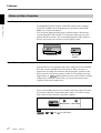

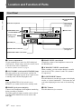


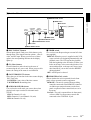


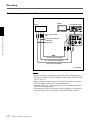


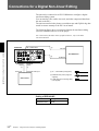
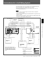
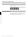

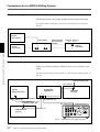
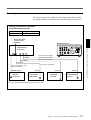
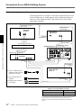


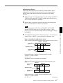


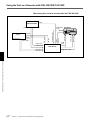


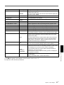

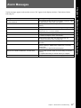
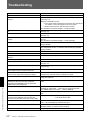


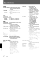
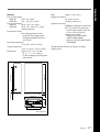


![RessqM, Enhanced Version of RESSQ [Javandel et al., 1984]](http://vs1.manualzilla.com/store/data/005674408_1-e8a4b9f66c80cdc83d847a710e5b4b1f-150x150.png)