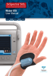
Download InSpectra - Hutchinson Technology BioMeasurement Division
Transcript
User Manual for interfacing the InSpectra™ StO2 Tissue Oxygenation Monitor model 650 with Philips Patient Monitoring Systems ENGLISH Français Deutsch Italiano Español User Manual for interfacing the InSpectra™ StO2 Tissue Oxygenation Monitor model 650 with Philips Patient Monitoring Systems Developed by: Hutchinson Technology Inc. BioMeasurement Division 40 West Highland Park Drive NE Hutchinson, MN 55350-9784 USA Service Centers United States and Canada Authorized European Representative Hutchinson Technology Inc. BioMeasurement Division 40 West Highland Park Drive NE Hutchinson, MN 55350-9784 USA Hutchinson Technology Inc. European Business Office IJsselburcht 3 6825 BS Arnhem The Netherlands Telephone: 800.419.1007 or 320.587.1926 Fax: 320.587.1555 Telephone: +31 26 365 33 70 Fax: +31 26 365 33 72 Email: [email protected] Website: www.htibiomeasurement.com Email: [email protected] 0086 ENGLISH Copyright 2009. Hutchinson Technology Incorporated. All Rights Reserved. InSpectra™ is a trademark of Hutchinson Technology Incorporated. Table of Contents Introduction............................................................................................................................... 4 Required System Components............................................................................................... 4 InSpectra™ StO2 System Components.............................................................................. 4 Philips Patient Monitoring System Components................................................................. 4 Intended Use/Indications for Use........................................................................................... 5 InSpectra™ StO2 Tissue Oxygenation Monitor Connectivity............................................. 5 InSpectra™ StO2 Tissue Oxygenation Monitor.................................................................. 5 Safety Notifications – Warnings.......................................................................................... 5 Safety Notifications – Cautions........................................................................................... 5 Connecting the InSpectra StO2 System................................................................................ 6 Configurations.......................................................................................................................... 7 Display of the Philips Patient Monitoring System................................................................ 7 Alerts.......................................................................................................................................... 7 Alarms.................................................................................................................................. 7 INOPs.................................................................................................................................. 8 Troubleshooting Guide............................................................................................................ 9 ENGLISH 3 Table of Contents Introduction The InSpectra™ StO2 Tissue Oxygenation Monitor model 650 allows communication with Philips Patient Monitoring Systems using a Philips VueLink Interface Module. Upon connection, the InSpectra StO2 System transfers patient StO2 and THI data as well as alarm messages and inoperable conditions (INOPs) to the Philips Patient Monitoring System. StO2 and THI data will be displayed as a digital reading only. NOTE: The VueLink Interface Module is unidirectional; the Philips Patient Monitoring System can display data received from the InSpectra StO2 System, but cannot control the InSpectra StO2 System. NOTE: Data transmission from the InSpectra StO2 System to the Philips Patient Monitoring System is delayed by up to seven (7) seconds. Required System Components InSpectra™ StO2 System Components • InSpectra StO2 Tissue Oxygenation Monitor with software v1.16 or greater. (figure 4.1) Philips Patient Monitoring System Components • Philips Patient Monitoring System with at least one open module rack. (figure 4.2) – Connection with the InSpectra StO2 System is possible to the following Philips Systems: > IntelliVue MP40, MP50, MP60, MP70, MP80, MP90 > CMS Monitors with software Rev. C or later > V24/26 Monitors • Philips VueLink Interface Module 1 NOTE: The VueLink Interface Module must be configured with the VueLink Open Interface Driver. • VueLink Open Interface Cable with 9-Pin Connector 2 NOTE: This item is available directly from Philips or your local Philips representative. figure 4.1 1 Additional Components • DB9 Null Modem Adapter with 6mm standoffs figure 4.2 ENGLISH 2 4 Introduction Intended Use/Indications for Use InSpectra™ StO2 Tissue Oxygenation Monitor Connectivity The InSpectra StO2 Tissue Oxygenation Monitor, model 650, includes the ability to transfer digital patient StO2 and THI to a Philips Patient Monitor using a null modem adapter and cable. This capability is intended to improve the ease of viewing StO2 and THI measurements. InSpectra™ StO2 Tissue Oxygenation Monitor The InSpectra StO2 Tissue Oxygenation Monitor is intended for use as a noninvasive monitoring system that measures an approximated value of percent hemoglobin oxygen saturation in tissue (StO2). The InSpectra StO2 Tissue Oxygenation Monitor is indicated for use in monitoring patients during circulatory or perfusion examinations of skeletal muscle or when there is a suspicion of compromised circulation. Safety Notifications – Warnings O WARNINGS alert the user to potential serious outcomes (death, injury, or adverse events) to the patient or user and contain information the user should know to avoid injuring patients and personnel. O WARNINGS help you to: • Identify the hazard. • Avoid the hazard. • Recognize the consequences. Safety Notifications – Cautions CAUTIONS alert the user to exercise care necessary for the effective use of the InSpectra StO2 System Connectivity. RX Only ENGLISH 5 Intended Use/Indications for Use Connecting the InSpectra™ StO2 System NOTE: The instructions listed below refer to the Philips IntelliVue MP50 Patient Monitor. The procedure to connect to other Philips Patient Monitoring System models may vary. To achieve a connection between the InSpectra StO2 System and a Philips Patient Monitoring System: 1. Insert the Philips VueLink Interface Module in the module rack of the Philips Monitor. 2. Turn ON the Philips Patient Monitor. 3. Connect the DB9 Null Modem Adapter 1 to the VueLink Open Interface Cable 2 using the 6mm standoffs. 4. Connect the other end of the DB9 Null Modem Adapter to the InSpectra StO2 1 System RS232 serial data port using 2 screws to tighten the adapter to the cable. (figure 6.1) 5. Connect the VueLink Open Interface Cable to the VueLink Interface Module. 6. Turn ON the InSpectra StO2 Monitor. 7. Enable the Philips Patient Monitoring mode on the InSpectra StO2 Monitor by selecting “Set Up” – “Connectivity” – “MPM” – “Philips VueLink”. A box (figure 6.2) will appear in the center of the screen confirming the selection; press the “Home” key to confirm setting. • The text “MPM-P” will appear on the screen confirming the InSpectra StO2 System is communicating in Philips VueLink mode. figure 6.1 NOTE: The Philips Patient Monitoring System will begin to display digital patient StO2 and THI data within 15–30 seconds of establishing a connection. If no data is received, refer to the Troubleshooting section of this guide. (figure 6.3) figure 6.2 CAUT ION: Any external IT device connected to this monitor must be certified according to IEC Standard 950. • Compliance with IEC Standard 60601-1-1 system requirements is required for all combinations of equipment connected to this monitor. • Any person connecting peripheral equipment to the data output port is configuring a medical system and is therefore responsible for compliance to system standard IEC Standard 60601-1-1 and the electromagnetic compatibility system standard IEC Standard 60601-1-2. O WARNING: Possible Electrical Shock Hazard. Do not simultaneously touch a patient and an external device, such as a computer, that is connected to the InSpectra StO2 Tissue Oxygenation Monitor through the USB port or the RS232 port. ENGLISH figure 6.3 6 Connecting the InSpectra™ StO2 System Configurations Display of the Philips Patient Monitoring System The following data from the InSpectra StO2 Monitor is available on the Philips Patient Monitoring System via the Philips VueLink Interface Module: Parameter Parameter Displayed on the Philips Patient Monitoring System Type StO2 StO2 Numeric THI THI Numeric Alerts The VueLink Open Interface Protocol distinguishes between two types of alerts: alarms and inoperable conditions (INOPs). NOTE: Only one alarm message, the one with the highest severity/priority, is displayed on the Philips Patient Monitoring System at the same time. All other functions related to alerts, i.e. blinking values or -?-, may occur simultaneously. NOTE: The Philips VueLink Interface Module does not allow the Philips Patient Monitoring System to generate audible signals for alarms generated by the InSpectra StO2 Monitor at the bedside. Alarms The VueLink Open Interface Protocol defines two levels of alarms: • Red Alarms: Indicate potentially life-threatening situations. Require immediate response. • Yellow Alarms: Indicate situations where response is necessary, but of less critical importance. InSpectra™ StO2 System Measurement data will cause the following yellow alarms (figure 7.1, Patient Monitoring System: Alarm Message Text HIGH StO2 ALARM LOW StO2 ALARM 1 ) on the Philips Description Either the High or Low StO2 alarm limit has activated. NOTE: When an alarm condition occurs in the InSpectra StO2 1 2 Monitor, the corresponding numeric StO2 value on the Philips Patient Monitoring System will blink. The corresponding THI value will not blink. The alarm message text 2 is displayed in the upper middle portion of the Philips Patient Monitoring System screen and is accompanied by a flashing yellow light. (figure 7.1) figure 7.1 ENGLISH 7 Configurations Alerts (continued) INOPs The VueLink Open Interface Protocol defines an INOP as a notice for the medical staff given by the equipment via displayed messages. Each INOP carries additional information on the validity of all related measurements or on the validity of a specific numeric value. INOPs are displayed in the upper left corner of the Philips Patient Monitoring System screen. INOP Message Text Corresponding InSpectra StO2 Monitor Message StO2 COMM ERROR ERROR: Communication Error StO2 DEFECTIVE LED ERROR: Defective LED or Optical Cable StO2 FAULTY SENSOR ERROR: Defective Sensor StO2 OVER TEMP ERROR: Monitor Over Temperature! StO2 SYSTEM CHECK System Check connected NO StO2 DATA No InSpectra StO2 Measurement: double dashes displayed (- -) NOTE: When one of the above listed INOPs occur on the InSpectra StO2 Monitor, the values for StO2 and THI on the Philips Patient Monitoring System will be replaced by a “-?-” message at the top of the screen 2 . (figure 8.1) 1 with the corresponding INOP 2 1 figure 8.1 ENGLISH Refer to page 9 of this guide for additional troubleshooting actions related to InSpectra StO2 Monitor messages. 8 Alerts Troubleshooting Guide For additional information, contact your Hutchinson Technology Inc. Representative or one of the Service Centers listed below. U.S. and Canada Service Center European Service Center Telephone: 800.419.1007 or 320.587.1926 Fax: 320.587.1555 Email: [email protected] Telephone: +31 26 365 33 71 Fax: +31 26 365 33 72 Email: [email protected] Symptoms Action No InSpectra™ StO2 or THI data is displayed on the Philips Patient Monitoring System. Verify the following: • Philips Patient Monitor is compatible with the VueLink Interface Module. • MPM-P Mode is enabled on the InSpectra™ StO2 Monitor. • Cable is correctly and fully connected to the RS232 port on the InSpectra StO2 Monitor. (Refer to the section; Connecting the InSpectra StO2 System, page 6) Unable to enable the Philips VueLink Mode (MPM-P) on the InSpectra StO2 Monitor. When data is being downloaded from the InSpectra StO2 Monitor, the monitor is in Standard Mode. Wait until download is complete and enable the Philips VueLink Mode (MPM-P). Enable the MPM-P Mode by selecting: 1. Set-Up 2. Connectivity 3. MPM 4. Philips VueLink 5. Home to confirm selection The StO2 and THI values on the Philips Patient Monitor do not match the InSpectra StO2 Monitor. Data transmission from the InSpectra StO2 System to the Philips Patient Monitoring System is delayed by up to seven (7) seconds. Unable to download data with the InSpectra™ StO2 Case Graphing Software. When the InSpectra StO2 Monitor is in MPM-P mode, there will be no output stream. Disable the MPM-P mode by selecting: 1. Set-Up 2. Connectivity 3. Standard Mode 4. Home to confirm selection For more information regarding use of the software, refer to the InSpectra™ StO2 Case Graphing Software User Manual. No alerts displayed. The VueLink Open Interface Module may not be configured to accept alarms; refer to the VueLink Open Interface documentation. ENGLISH 9 Troubleshooting Guide Troubleshooting Guide (continued) Alert Conditions Philips Patient Monitor Alert Message StO2 COMM ERROR StO2 DEFECTIVE LED StO2 FAULTY SENSOR ENGLISH StO2 OVER TEMP 10 Troubleshooting Guide Corresponding Message on the InSpectra™ StO2 Monitor Situation Action ERROR: Communication Error There is an internal communication error inside the InSpectra StO2 Monitor. 1. T urn OFF power to the InSpectra StO2 Monitor, then ON. 2. If error occurs again, contact the Hutchinson Technology Service Center. ERROR: Defective LED or Optical Cable 1. Turn OFF power to the InSpectra StO2 Monitor, then ON. 2. Disconnect and reconnect The InSpectra StO2 sensor. Monitor is detecting too little light to make an 3. Connect a new sensor. accurate measurement. 4. Contact the Hutchinson Technology Service Center if error message continues after trying a new sensor. ERROR: Defective Sensor The electrical connection to the sensor may be faulty. The cause may be in either the optical cable or sensor. ERROR: Monitor Over Temperature! 1. Turn OFF the InSpectra StO2 Monitor and allow cooling to ambient temperature. 2. Ensure that the inlet grill on the The internal bottom of the monitor is clear of temperature of the obstruction (place monitor on a InSpectra StO2 Monitor hard flat surface). has exceeded 55°C. 3. Check that fan is running when AC power is connected; if not, contact the Hutchinson Technology Service Center. 1. Disconnect and reconnect sensor. 2. Connect a new sensor. 3. Contact the Hutchinson Technology Service Center if error message continues after trying a new sensor. Troubleshooting Guide (continued) Alert Conditions (continued) Philips Patient Monitor Alert Message StO2 SYSTEM CHECK NO StO2 DATA Corresponding Message on the InSpectra™ StO2 Monitor System Check Connected Situation Action The InSpectra StO2 Monitor is connected to a System Check. 1. Disconnect System Check and attach sensor to receive patient StO2 and THI readings. Sensor may not be placed properly over tissue that has adequate hemoglobin content. 1. Adjust placement of sensor and attempt to maximize THI value. Excessive residue under sensor. 1. Clean patient skin where sensor will be attached. Excessive ambient light may be entering the sensor. 1. Ensure the sensor shield is fully adhered to the patient. 2. Reduce the level of ambient light near the sensor or cover the sensor with additional light absorbing material such as a dark towel. Insufficient optical signal. The optical cable and/or sensor may be damaged. 1. Connect the optical cable to the System Check to verify the monitor is working. 2. Replace the sensor. 3. If error condition persists, contact the Hutchinson Technology Service Center. InSpectra StO2 System error. 1. Turn OFF power to the InSpectra StO2 Monitor, then ON. 2. If the error condition persists, contact the Hutchinson Technology Service Center. No InSpectra StO2 Measurement: double dashes displayed (- -). Refer to the Philips Patient Monitoring System Manual for alarm messages not shown here. ENGLISH 11 Troubleshooting Guide The InSpectra™ StO 2 Tissue Oxygenation Monitor is a noninvasive monitoring system that measures an approximated value of percent hemoglobin oxygen saturation in tissue (StO2). Visit us online at www.htibiomeasurement.com for our full contact information and Instructions for Use. ENGLISH InSpectra is a registered trademark of Hutchinson Technology Inc. in the United States of America, the European Community, Canada, China and Japan. ©2009 Hutchinson Technology Inc. 5022061 A 03/09 All Rights Reserved. Printed in the USA. RX ONLY. 0086 Manuel de l’opérateur pour l’interfaçage de l’InSpectra™ StO2 Tissue Oxygenation Monitor (Moniteur d’oxygénation des tissus), modèle 650, avec Philips Patient Monitoring Systems ENGLISH Français Deutsch Italiano Español Manuel de l’opérateur pour la réalisation de l’interfaçage de l’InSpectra™ StO2 Tissue Oxygenation Monitor (Moniteur d’oxygénation des tissus), modèle 650, avec Philips Patient Monitoring Systems Développé par : Hutchinson Technology Inc. BioMeasurement Division 40 West Highland Park Drive NE Hutchinson, MN 55350-9784 États-Unis Centres de service après-vente États-Unis et Canada Représentant autorisé en Europe Hutchinson Technology Inc. BioMeasurement Division 40 West Highland Park Drive NE Hutchinson, MN 55350-9784 États-Unis Hutchinson Technology Inc. Bureau commercial européen IJsselburcht 3 6825 BS Arnhem Pays-Bas Téléphone : +1 800.419.1007 ou +1 320.587.1926 Télécopie : +1 320.587.1555 Téléphone : +31 26 365 33 70 Télécopie : +31 26 365 33 72 Courrier électronique : [email protected] Site Web : www.htibiomeasurement.com Courrier électronique : [email protected] 0086 FRANÇAIS Copyright 2009. Hutchinson Technology Incorporated. Tous droits réservés. InSpectra™ est une marque commerciale de Hutchinson Technology Incorporated. Table des matières Introduction............................................................................................................................... 4 Éléments du système requis................................................................................................... 4 Éléments du système InSpectra™ StO2............................................................................. 4 Éléments du Philips Patient Monitoring System.................................................................. 4 Utilisation envisagée/Indications pour l’utilisation............................................................. 5 Connectivité de l’InSpectra™ StO2 Tissue Oxygenation Monitor (Moniteur d’oxygénation des tissus).................................................................................... 5 InSpectra™ StO2 Tissue Oxygenation Monitor (Moniteur d’oxygénation des tissus)........ 5 Notes de sécurité - Avertissements.................................................................................... 5 Notes de sécurité - Attention............................................................................................... 5 Connexion du système InSpectra StO2................................................................................. 6 Configurations.......................................................................................................................... 7 Affichage du Philips Patient Monitoring System................................................................. 7 Alertes........................................................................................................................................ 7 Alarmes................................................................................................................................ 7 INOP.................................................................................................................................... 8 Guide de dépannage................................................................................................................ 9 FRANÇAIS 3 Table des matières Introduction Le modèle 650 d’InSpectra™ StO2 Tissue Oxygenation Monitor (Moniteur d’oxygénation des tissus) permet de communiquer avec le Philips Patient Monitoring Systems à l’aide du VueLink Interface Module de Philips. Lorsqu’il se connecte, le système InSpectra StO2 transfère les données StO2 et THI du patient ainsi que les messages d’alarme et les conditions d’inopérabilité (INOP) au Système de contrôle de patients Philips. L’affichage des données StO2 et THI est à lecture numérique uniquement. Remarque : Le VueLink Interface Module est unidirectionnel ; le Philips Patient Monitoring System peut afficher les données reçues depuis le système InSpectra StO2, mais ne peut pas le commander. Remarque : La transmission des données depuis le système InSpectra StO2 vers le Philips Patient Monitoring System est retardée d’au plus sept (7) secondes. Éléments du système requis Éléments du système InSpectra™ StO2 • InSpectra StO2 Tissue Oxygenation Monitor (Moniteur d’oxygénation des tissus) avec le logiciel v1.16 ou supérieure. (figure 4.1) Éléments du Philips Patient Monitoring System • Philips Patient Monitoring System avec au moins un rack ouvert pour le module. (figure 4.2) – Les systèmes Philips suivants peuvent se connecter au système InSpectra StO2 : > IntelliVue MP40, MP50, MP60, MP70, MP80, MP90 > Moniteurs CMS avec la révision C du logiciel ou ultérieur > Moniteurs V24/26 • VueLink Interface Module de Philips 1 REMARQUE : Le VueLink Interface Module de Philips doit être configuré avec le pilote VueLink Open Interface. figure 4.1 1 • Câble VueLink Open Interface avec connecteur 9 broches 2 REMARQUE : Vous pouvez vous procurer cet article directement auprès de Philips ou de votre représentant local Philips. Éléments supplémentaires • Adaptateur Null-Modem DB9 avec colonettes 6 mm figure 4.2 FRANÇAIS 2 4 Introduction Utilisation envisagée/Indications pour l’utilisation Connectivité de l’InSpectra™ StO2 Tissue Oxygenation Monitor (Moniteur d’oxygénation des tissus) Le modèle 650 d’InSpectra StO2 Tissue Oxygenation Monitor (Moniteur d’oxygénation des tissus) permet le transfert de données numériques StO2 et THI des patients vers un Philips Patient Monitoring System à l’aide d’un adaptateur null-modem et d’un câble. Cette possibilité vise à rendre les mesures StO2 et THI plus lisibles. InSpectra™ StO2 Tissue Oxygenation Monitor (Moniteur d’oxygénation des tissus) L’InSpectra StO2 Tissue Oxygenation Monitor (Moniteur d’oxygénation des tissus) est conçu pour être utilisé comme système de contrôle non-invasif mesurant une valeur approximative du pourcentage de saturation en oxygène de l’hémoglobine des tissus (StO2). L’InSpectra StO2 Tissue Oxygenation Monitor (Moniteur d’oxygénation des tissus) est indiqué pour être utilisé dans le cadre du contrôle des patients qui subissent un examen circulatoire ou de perfusion du muscle squelettique ou en cas de suspicion de difficultés circulatoires. Notes de sécurité - Avertissements O Les AVERTISSEMENTS alertent l’opérateur sur des résultats potentiels graves (mort, lésion ou événements indésirables) pour le patient ou l’opérateur et contiennent des informations que l’opérateur doit connaître afin d’éviter de blesser les patients et le personnel. O Les AVERTISSEMENTS vous aident à : • Identifier le danger • Éviter le danger • Reconnaître les conséquences. Notes de sécurité - Attention L a note de sécurité ATTENTION indique à l’opérateur de faire preuve de l’attention nécessaire à une utilisation efficace de la connectivité du système InSpectra StO2. Uniquement sur ordonnance FRANÇAIS 5 Utilisation envisagée/Indications pour l’utilisation Connexion du système InSpectra™ StO2 REMARQUE : Les instructions ci-dessous font référence au moniteur patient IntelliVue MP50 de Philips. La procédure de connexion à d’autres systèmes Philips Patient Monitoring System peut être différente. Pour connecter le système InSpectra StO2 à un Philips Patient Monitoring System : 1. Insérez le VueLink Interface Module de Philips dans le rack du moniteur Philips. 2. Allumez le moniteur patient Philips. 3. Branchez l’adaptateur null-modem DB9 1 au câble VueLink Open Interface 2 à l’aide des colonettes 6 mm. 4. Branchez l’autre extrémité de l’adaptateur null-modem DB9 au port série RS232 du 1 système InSpectra StO2 en serrant les 2 vis pour fixer l’adaptateur au câble. (figure 6.1) 5. Branchez le câble VueLink Open Interface au VueLink Interface Module. 6. Allumez l’InSpectra StO2 Monitor. 7. Activez le mode Contrôle de patient Philips sur l’InSpectra StO2 Monitor en sélectionnant « Réglage », « Connectivité », « MPM », « Philips VueLink ». Une fenêtre (figure 6.2) s’affiche au centre de l’écran pour confirmer la sélection ; appuyez sur la touche « Accueil » pour confirmer le réglage. • Le texte « MPM-P » s’affiche à l’écran, confirmant que le système InSpectra StO2 communique en mode Philips VueLink. figure 6.1 REMARQUE : Le Philips Patient Monitoring System commence à afficher les données numériques StO2 et THI du patient dans un délai de 15 à 30 secondes suivant l’établissement de la connexion. Si aucune donnée n’est reçue, reportez-vous à la section Dépannage de ce guide. (figure 6.3) figure 6.2 ENTION : Tout dispositif informatique externe connecté à ce ATT moniteur doit être certifié conforme à la norme CEI 950. • Toute combinaison d’équipements connectés à ce moniteur doit respecter les exigences système de la norme CEI 60601-1-1. • Toute personne connectant un équipement périphérique au port de sortie des données configure un système médical et est, par conséquent, responsable de la conformité à la norme CEI 60601-1-1 du système et à la norme CEI 60601-1-2 sur la compatibilité électromagnétique du système. O AVERTISSEMENT : Risque de choc électrique. Ne touchez pas en même temps un patient et un dispositif externe, tel qu’un ordinateur relié à l’InSpectra StO2 Tissue Oxygenation Monitor (Moniteur d’oxygénation des tissus) par les ports USB ou RS232. FRANÇAIS figure 6.3 6 Connexion du système InSpectra™ StO2 Configurations Affichage du Philips Patient Monitoring System Les données suivantes de l’InSpectra StO2 Monitor sont disponibles sur le Philips Patient Monitoring System via le VueLink Interface Module de Philips : Paramètre Paramètre affiché sur le Philips Patient Monitoring System Type StO2 StO2 Numérique THI THI Numérique Alertes Le protocole VueLink Open Interface fait la distinction entre deux types d’alertes : les alarmes et les conditions d’inopérabilité (INOP). REMARQUE : Un seul message d’alarme à la fois, celui dont la gravité/priorité est la plus élevée, s’affiche sur le Philips Patient Monitoring System. Toutes les autres fonctions d’alerte (valeurs clignotantes ou -?-) peuvent fonctionner simultanément REMARQUE : Le VueLink Interface Module de Philips ne permet pas au Philips Patient Monitoring System de générer des signaux audibles en cas d’alarme générée par l’InSpectra StO2 Monitor dans la chambre. Alarmes Le protocole VueLink Open Interface définit deux niveaux d’alarme : • Alarmes rouges : Indiquent des situations potentiellement mortelles. Exigent une réponse immédiate. • Alarmes jaunes : Indiquent des situations nécessitant une réponse, mais moins critiques. Les données de mesure du système InSpectra™ StO2 entraînent le déclenchement des alarmes jaunes suivantes (figure 7.1, 1 ) sur le Philips Patient Monitoring System : Texte du message d’alarme Alarme Haute StO2 Alarme Basse StO2 Description Le seuil d’alarme haute ou basse StO2 a été activé. REMARQUE : Lorsqu’une alarme se déclenche sur l’InSpectra 1 2 StO2 Monitor, la valeur numérique de StO2 correspondante clignote sur le Philips Patient Monitoring System. La valeur de THI correspondante ne clignote pas. Le texte du message d’alarme 2 s’affiche dans la partie supérieure centrale de l’écran du Philips Patient Monitoring System et il s’accompagne d’un voyant jaune clignotant. (figure 7.1) 7 Configurations FRANÇAIS figure 7.1 Alertes (suite) INOP Le protocole VueLink Open Interface définit un INOP comme étant un avertissement donné au personnel médical via des messages affichés. Chaque INOP apporte des informations supplémentaires sur la validité de l’ensemble des mesures associées ou sur la validité d’une valeur numérique spécifique. Les INOP s’affichent en haut à gauche de l’écran du Philips Patient Monitoring System. Texte du message INOP Message correspondant de l’InSpectra StO2 Monitor Erreur Comm StO2 Erreur : Erreur de transmission LED Défect. StO2 Erreur : LED ou câble optique défectueux Sonde défect. StO2 Erreur : Capteur défectueux Temp élevée StO2 Erreur : Température du moniteur trop élevée System Check StO2 System Check reliée Aucune donnée StO2 Aucune mesure InSpectra StO2 : un double tiret s’affiche (- -) REMARQUE : Lorsque l’un des INOP ci-dessus se produit sur l’InSpectra StO2 Monitor, les valeurs de StO2 et de THI du Philips Patient Monitoring System sont remplacées par “ -?- ” correspondant en haut de l’écran 2 . (figure 8.1) 1 avec le message INOP 2 1 figure 8.1 FRANÇAIS Reportez-vous à la page 9 de ce guide pour connaître les autres mesures de dépannage associées aux messages de l’InSpectra StO2 Monitor. 8 Alertes Guide de dépannage Pour plus de renseignements, veuillez contacter votre représentant de Hutchinson Technology Inc. ou l’un des centres de service après-vente indiqués dans la liste ci-dessous. Centre de service après-vente aux États-Unis et Canada Centre de Service après-vente européen Téléphone : +1 800.419.1007 ou +1 320.587.1926 Télécopie : +1 320.587.1555 Courrier électronique : [email protected] Téléphone : +31 26 365 33 71 Télécopie : +31 26 365 33 72 Courrier électronique : [email protected] Symptômes Action Aucune donnée StO2 ou THI de l’InSpectra™ ne s’affiche sur le Philips Patient Monitoring System. Vérifiez que : • Le moniteur patient Philips est compatible avec le VueLink Interface Module. • Le mode MPM-P est activé sur l’InSpectra™ StO2 Monitor. • Le câble est correctement et complètement branché au port RS232 de l’InSpectra StO2 Monitor. (Se reporter à la section Connexion du système InSpectra StO2, page 6) Impossible d’activer le mode Philips VueLink (MPM-P) sur l’InSpectra StO2 Monitor. Lorsque des données sont téléchargées depuis l’InSpectra StO2 Monitor, le moniteur est en mode standard. Attendez la fin du téléchargement et activez le mode Philips VueLink (MPM-P). Activez le mode MPM-P en sélectionnant : 1. Réglage 2. Connectivité 3. MPM 4. Philips VueLink 5. Accueil pour confirmer la sélection Les valeurs StO2 et THI du moniteur patient Philips ne correspondent pas à celles de l’InSpectra StO2 Monitor. La transmission des données depuis le système InSpectra StO2 vers le Philips Patient Monitoring System est retardée d’au plus sept (7) secondes. Impossible de télécharger des données avec le logiciel InSpectra™ StO2 Case Graphing. Lorsque l’InSpectra StO2 Monitor est en mode MPM-P, il n’y a aucun flux en sortie. Désactivez le mode MPM-P en sélectionnant : 1. Réglage 2. Connectivité 3. Mode standard 4. Accueil pour confirmer la sélection Pour plus d’informations concernant l’utilisation du logiciel, reportez-vous au manuel de l’opérateur du logiciel InSpectra™ StO2 Case Graphing. Aucune alerte n’est affichée. Le module VueLink Open Interface n’est peut-être pas configuré pour accepter les alarmes ; reportez-vous à la documentation VueLink Open Interface. FRANÇAIS 9 Guide de dépannage Guide de dépannage (suite) Conditions d’alertes Message d’alerte du moniteur patient Philips Erreur Comm StO2 LED Défect. StO2 Sonde défect. StO2 FRANÇAIS Temp. élevée StO2 10 Guide de dépannage Message correspondant sur l’InSpectra™ StO2 Monitor Situation Action Il y a une erreur de communication interne dans l’InSpectra StO2 Monitor. 1. Éteignez l’InSpectra StO2 Monitor, puis rallumez-le. 2. Si l’erreur apparaît à nouveau, contactez le Centre de service après-vente d’Hutchinson Technology. Erreur : LED ou câble optique défectueux L’InSpectra StO2 Monitor détecte trop peu de lumière pour pouvoir mesurer avec exactitude. 1. Éteignez l’InSpectra StO2 Monitor, puis rallumez-le. 2. Déconnectez et reconnectez la sonde. 3. Connectez une nouvelle sonde. 4. Contactez le Centre de service après-vente d’Hutchinson Technology si le message d’erreur continue après l’essai avec une nouvelle sonde. Erreur : Capteur défectueuse 1. Déconnectez et reconnectez Il se peut que le la sonde. connecteur électrique 2. Connectez une nouvelle sonde. de la sonde soit 3. Contactez le Centre de service défectueux. La cause après-vente d’Hutchinson peut provenir soit du Technology si le message câble optique, soit de la d’erreur continue après l’essai sonde. avec une nouvelle sonde. Erreur : de transmission Erreur : Température du moniteur trop élevée La température interne de l’InSpectra StO2 Monitor a dépassé 55°C. 1. Éteignez l’InSpectra StO2 Monitor et laissez-le refroidir jusqu’à ce qu’il atteigne la température ambiante. 2. Vérifiez que la grille d’entrée dans la partie inférieure du moniteur n’est obstruée d’aucune manière (placez le moniteur sur une surface plane et dure). 3. Vérifiez que le ventilateur est en marche lorsque la source de courant alternatif est liée ; dans le cas contraire, contactez le Centre de service après-vente d’Hutchinson Technology. Guide de dépannage (suite) Conditions d’alertes (suite) Message d’alerte du moniteur patient Philips System Check StO2 Message correspondant sur l’InSpectra™ StO2 Monitor System Check reliée Situation Action L’InSpectra StO2 Monitor est connecté à une System Check. 1. Déconnectez la System Check et fixez la sonde de façon à recevoir les résultats StO2 et THI du patient. La sonde peut ne pas être placée 1. Ajustez le positionnement de la correctement sur le sonde et essayez de maximiser tissu qui a un contenu la valeur THI. d’hémoglobine adéquat. Aucune donnée StO2 Aucune mesure InSpectra StO2 : un double tiret s’affiche (- -). Excès de résidus sous la sonde. 1. Nettoyez la peau du patient à l’endroit où la sonde est attachée. Il se peut que trop de lumière ambiante entre dans la sonde. 1. Assurez-vous que la protection de la sonde adhère totalement au patient. 2. Diminuez le niveau de lumière ambiante près de la sonde ou recouvrez la sonde de tissus absorbant la lumière, tels qu’une serviette de toilette de couleur sombre. Signal optique insuffisant. Il se peut que le câble optique et/ou la sonde soient endommagés. 1. Reliez le câble optique à la System Check afin de vérifier que le moniteur fonctionne. 2. Remplacez la sonde. 3. Si l’erreur persiste, contactez le Centre de service après-vente d’Hutchinson Technology. Erreur du système InSpectra StO2. 1. Éteignez l’InSpectra StO2 Monitor, puis rallumez-le. 2. Si l’erreur persiste, contactez le Centre de service après-vente d’Hutchinson Technology. 11 Guide de dépannage FRANÇAIS Reportez-vous au Manuel Philips Patient Monitoring System pour les messages d’alarme qui ne figurent pas ici. FRANÇAIS InSpectra™ StO 2 Tissue Oxygenation Monitor (Moniteur d’oxygénation des tissus) est un système de contrôle non-invasif mesurant une valeur approximative du pourcentage de saturation en oxygène de l’hémoglobine des tissus (StO2). Consultez le site www.htibiomeasurement.com pour connaître nos coordonnées complètes ainsi que les instructions d’utilisation. 12 InSpectra est une marque déposée d’Hutchinson Technology Inc. aux États-Unis d’Amérique, dans la Communauté Européenne, au Canada, en Chine et au Japon. ©2009 Hutchinson Technology Inc. 5022061 A 03/09 Tous droits réservés. Imprimé aux États-Unis. UNIQUEMENT SUR ORDONNANCE. 0086 Gebrauchsanleitung zum Koppeln des InSpectra™ StO2 Tissue Oxygenation Monitors, modell 650, mit den Philips Patient Monitoring-Systemen english Français Deutsch Italiano Español Gebrauchsanleitung zum Koppeln des InSpectra™ StO2 Tissue Oxygenation Monitors, modell 650, mit Philips Patient Monitoring-Systemen Entwickelt von: Hutchinson Technology Inc. BioMeasurement Division 40 West Highland Park Drive NE Hutchinson, MN 55350-9784 USA Kundendienstzentren Vereinigte Staaten und Kanada Autorisierte Vertretung in Europa Hutchinson Technology Inc. BioMeasurement Division 40 West Highland Park Drive NE Hutchinson, MN 55350-9784 USA Hutchinson Technology Inc. Europäische Niederlassung IJsselburcht 3 6825 BS Arnhem Niederlande Telefon: +1 800 419 1007 oder +1 320 587 1926 Fax: +1 320 587 1555 Telefon: +31 26 365 33 70 Fax: +31 26 365 33 72 E-Mail: [email protected] Website: www.htibiomeasurement.com. E-Mail: [email protected] 0086 DEUTSCH Copyright 2009. Hutchinson Technology Incorporated. Alle Rechte vorbehalten. InSpectra™ ist eine Marke der Hutchinson Technology Incorporated. Inhaltsverzeichnis Einführung................................................................................................................................. 4 Erforderliche Systemkomponenten....................................................................................... 4 InSpectra™ StO2 Systemkomponenten.............................................................................. 4 Komponenten des Philips Patient Monitoring-Systems...................................................... 4 Bestimmung/Indikationen....................................................................................................... 5 InSpectra™ StO2 Tissue Oxygenation Monitor – Konnektivität......................................... 5 InSpectra™ StO2 Tissue Oxygenation Monitor.................................................................. 5 Sicherheitshinweise – Warnungen...................................................................................... 5 Sicherheitshinweise – Vorsichtshinweise............................................................................ 5 Anschließen des InSpectra StO2 Systems............................................................................ 6 Konfigurationen........................................................................................................................ 7 Anzeige des Philips Patient Monitoring-Systems............................................................... 7 Warnhinweise............................................................................................................................ 7 Alarme................................................................................................................................. 7 INOPs.................................................................................................................................. 8 Fehlersuchanleitung................................................................................................................ 9 DEUTSCH 3 Inhaltsverzeichnis Einführung Der InSpectra™ StO2 Tissue Oxygenation Monitor, modell 650, ermöglicht mithilfe eines Philips VueLink Interface Module die Kommunikation mit den Philips Patient Monitoring-Systemen.– Nachdem das InSpectra StO2 System angeschlossen wurde, überträgt es StO2- und THI-Daten des Patienten sowie Alarmmeldungen und sogenannte INOP-Meldungen (Meldung, dass der einwandfreie Betrieb des Geräts nicht gewährleistet werden kann) an das Philips Patient Monitoring-System. StO2- und THI-Daten werden nur als digitale Werte angezeigt. HINWEIS: Das VueLink Interface Module arbeitet nur in einer Richtung. Das bedeutet, dass das Philips Patient Monitoring-System die vom InSpectra StO2 System empfangenen Daten zwar anzeigen, aber das InSpectra StO2 System nicht steuern kann. HINWEIS: Die Datenübertragung vom InSpectra StO2 System in das Philips Patient Monitoring System verzögert sich um bis zu sieben (7) Sekunden. Erforderliche Systemkomponenten InSpectra™ StO2 Systemkomponenten • InSpectra StO2 Tissue Oxygenation Monitor mit Softwareversion 1.16 oder höher. (Abbildung 4.1) Komponenten des Philips Patient Monitoring-Systems • Philips Patient Monitoring-System mit mindestens einem offenen Modul-Rack. (Abbildung 4.2) – Das InSpectra StO2 System kann an folgende Philips-Systeme angeschlossen werden: > IntelliVue MP40, MP50, MP60, MP70, MP80, MP90 > CMS-Monitore mit Software-Rev. C oder höher > V24/26-Monitore • Philips VueLink Interface Module 1 HINWEIS: Das VueLink Interface Module muss mit dem VueLink Open Interface-Treiber konfiguriert werden. • VueLink Open Interface-Kabel mit 9-poligem Anschluss 2 HINWEIS: Diese Option ist direkt von Philips oder Ihrer Philips-Vertretung vor Ort erhältlich. Abbildung 4.1 1 Zusätzliche Komponenten • DB9-Nullmodem-Adapter mit 6-mm-Abstandshaltern Abbildung 4.2 DEUTSCH 2 4 Einführung Bestimmung/Indikationen InSpectra™ StO2 Tissue Oxygenation Monitor – Konnektivität Der InSpectra StO2 Tissue Oxygenation Monitor, modell 650, ermöglicht die Übertragung digitaler PatientenStO2- und THI-Daten zu einem Philips Patient Monitor über einen Nullmodemadapter und ein Nullmodemkabel. Damit soll die Anzeige von StO2- und THI-Messungen erleichtert werden. InSpectra™ StO2 Tissue Oxygenation Monitor Der InSpectra StO2 Tissue Oxygenation Monitor ist zur Benutzung als nichtinvasives Überwachungssystem bestimmt, das einen Näherungswert der prozentualen Sauerstoffsättigung des Hämoglobins im Gewebe (StO2) misst. Die Benutzung des InSpectra StO2 Tissue Oxygenation Monitors ist zur Überwachung von Patienten während Kreislauf- oder Perfusionsuntersuchungen der Skelettmuskeln angezeigt. Das Gerät kann auch bei vermuteten Kreislaufproblemen eingesetzt werden. Sicherheitshinweise – Warnungen O WARNUNGEN warnen den Benutzer vor potenziell ernsthaften Folgen (Tod, Verletzung oder nachteilige Ereignisse) für den Patienten und den Anwender und enthalten Informationen, wie man die Verletzung der Patienten und des Personals vermeiden kann. O WARNUNGEN helfen Ihnen: • die Gefahr zu erkennen. • die Gefahr zu vermeiden. • die Folgen zu erkennen. Sicherheitshinweise – Vorsichtshinweise it VORSICHT bezeichnete Hinweise fordern den Anwender dazu auf, entsprechende Vorsicht walten zu M lassen, damit eine effiziente Konnektivität des InSpectra StO2 Systems gewährleistet werden kann. Nur RX DEUTSCH 5 Bestimmung/Indikationen Anschließen des InSpectra™ StO2 Systems HINWEIS: Die unten angegebenen Anweisungen beziehen sich auf den Philips Patient Monitor IntelliVue MP50. Die Vorgehensweise zum Anschließen an ein anderes modell der Philips Patient Monitoring-Systeme kann etwas von den hier beschriebenen Schritten abweichen. So wird eine Verbindung zwischen dem InSpectra StO2 System und einem Philips Patient Monitoring-System hergestellt: 1. Schieben Sie das Philips VueLink Interface Module in das Modul-Rack des PhilipsMonitors ein. 2. S chalten Sie den Philips Patient Monitor ein. 3. Schließen Sie den DB9-Nullmodem adapter 1 an das VueLink Open Interface-Kabel 2 an. Verwenden Sie 1 2 dabei die 6-mm-Abstandshalter. 4. Schließen Sie das andere Ende des DB9Nullmodemadapters an den seriellen RS232Datenanschluss des InSpectra StO2 Systems an. Schrauben Sie den Adapter dabei am Kabel fest. (Abbildung 6.1) 5. Schließen Sie das VueLink Open Interface-Kabel am VueLink Interface Module an. 6. Schalten Sie den InSpectra StO2 Monitor ein. 7. Aktivieren Sie den Philips Patient Monitoring-Modus am InSpectra StO2 Monitor durch Auswahl von „Set up“ – „Verbindung“ – „MPM“ – „Philips VueLink“. In der Bildschirmmitte erscheint ein Feld (Abbildung 6.2), das die Auswahl bestätigt. Drücken Sie die Starttaste, um die Einstellung zu bestätigen. • Der Text „MPM-P“ auf dem Bildschirm bestätigt, dass das InSpectra StO2 System mit dem Philips-VueLink-Modus kommuniziert. HINWEIS: Das Philips Patient Monitoring-System beginnt mit der Anzeige der digitalen StO2- und THI-Daten des Patienten innerhalb von 15 bis 30 Sekunden nach der Herstellung einer Verbindung. Wenn keine Daten empfangen werden, lesen Sie den Abschnitt zur Fehlersuche in dieser Anleitung. (Abbildung 6.3) Abbildung 6.1 Abbildung 6.2 VORSICHT: Jedes externe IT-Gerät, das mit diesem Monitor DEUTSCH verbunden wird, muss nach dem IEC Standard 950 zertifiziert sein. • Alle Systemkombinationen, die mit diesem Monitor verbunden werden, müssen den Systemanforderungen nach dem IEC Standard 60601-1-1 genügen. • Jede Person, die eine Peripherieeinrichtung mit dem Daten ausgangsport verbindet, konfiguriert damit ein medizinisches System und ist daher für die Einhaltung der Anforderungen gemäß IEC Standard 60601-1-1 und gemäß dem Standard zur elektromagnetischen Kompatibilität, IEC Standard 60601-1-2, verantwortlich. O WARNUNG: Mögliche Stromschlaggefahr. Berühren Sie nie gleichzeitig Abbildung 6.3 den Patienten und ein externes Gerät (z. B. einen PC), das durch den USB- oder RS232-Anschluss mit dem InSpectra StO2 Tissue Oxygenation Monitor verbunden ist. 6 Anschließen des InSpectra™ StO2 Systems Konfigurationen Anzeige des Philips Patient Monitoring-Systems Die folgenden Daten vom InSpectra StO2 Monitor stehen über das Philips VueLink Interface Module auf dem Philips Patient Monitoring-System zur Verfügung: Parameter Auf dem Philips Patient MonitoringSystem angezeigter Parameter Typ StO2 StO2 Numerisch THI THI Numerisch Warnhinweise Das VueLink Open Interface Protocol unterscheidet zwischen zwei Arten von Warnhinweisen: Alarme und INOPs. HINWEIS: Auf dem Philips Patient Monitoring-System wird jeweils nur eine Alarmmeldung angezeigt – und zwar diejenige mit dem höchsten Schweregrad bzw. der höchsten Priorität. Alle weiteren Funktionen im Zusammenhang mit Alarmen, d. h. blinkende Werte oder -?-, können gleichzeitig auftreten. HINWEIS: Das Philips VueLink Interface Module erlaubt es dem Philips Patient Monitoring-System nicht, hörbare Signale zu generieren, die von Alarmen des bettseitigen InSpectra StO2 Monitors generiert wurden. Alarme Das VueLink Open Interface Protocol definiert zwei Alarmstufen: • Rote Alarme: Weisen auf möglicherweise lebensbedrohliche Situationen hin. Erfordern eine sofortige Reaktion. • Gelbe Alarme: Weisen auf Situationen hin, in denen eine Reaktion erforderlich ist, sind jedoch von weniger kritischer Bedeutung. InSpectra™ StO2 Systemmessdaten rufen am Philips Patient Monitoring-System die folgenden gelben Alarme hervor (Abbildung 7.1, 1 ): Alarmmeldungstext StO2 Obergrenze StO2 Untergrenze Beschreibung Die StO2 Ober- oder Untergrenze wurde überschritten. HINWEIS: Wenn im InSpectra StO2 Monitor eine Alarmbedingung auftritt, blinkt der entsprechende numerische StO2-Wert am Philips Patient Monitoring-System. Der entsprechende THI-Wert blinkt nicht. Der Alarmmeldungstext 2 wird im oberen mittleren Teil des Bildschirms des Philips Patient Monitoring-Systems angezeigt und von einem gelben Blinklicht begleitet. (Abbildung 7.1) 1 2 DEUTSCH Abbildung 7.1 7 Konfigurationen Warnhinweise (Fortsetzung) INOPs Das VueLink Open Interface Protocol definiert eine INOP als Hinweis für das medizinische Personal. Dieser wird durch das Gerät in Form angezeigter Meldungen ausgegeben. Jede INOP liefert Zusatzinformationen über die Gültigkeit aller entsprechenden Messungen oder über die Gültigkeit eines bestimmten numerischen Wertes. INOPs werden oben links auf dem Bildschirm des Philips Patient Monitoring-Systems angezeigt. INOP-Meldungstext Entsprechende InSpectra StO2 Monitor-Meldung Fehl. b. Dat.aust. Fehler: Kommunikationsfehler StO2-LED Defekt Fehler: LED oder LWL-Kabel defekt StO2-Sondenfehler Fehler: Defekter Fühler StO2-Übertemp. Fehler: Über-temperatur Monitor! StO2-System Check System Check angeschlossen Keine StO2-Daten Keine InSpectra StO2 Messung: 2 Striche (- -) werden angezeigt HINWEIS: Wenn eine der o.g. INOPs am InSpectra StO2 Monitor angezeigt wird, wird anstelle der Werte für StO2 und THI am Philips Patient Monitoring-System „-?-“ Bildschirmoberseite 2 angezeigt. (Abbildung 8.1) 1 mit der entsprechenden INOP-Meldung an der 2 1 Abbildung 8.1 DEUTSCH Weitere Aktionen zur Fehlersuche im Zusammenhang mit den Meldungen auf dem InSpectra StO2 Monitor können der Seite 9 dieses Handbuchs entnommen werden. 8 Warnhinweise Fehlersuchanleitung Weitere Informationen erhalten Sie vom Vertreter von Hutchinson Technology Inc. oder bei einem der unten aufgelisteten Kundendienstzentren. Kundendienstzentren in den USA und Kanada Kundendienstzentrum in Europa Telefon: +1 800 419 1007 oder +1 320 587 1926 Fax: +1 320 587 1555 E-Mail: [email protected] Telefon: +31 26 365 33 71 Fax: +31 26 365 33 72 E-Mail: [email protected] Maßnahmen Auf dem Philips Patient MonitoringSystem werden keine InSpectra™ StO2oder THI-Daten angezeigt. Prüfen Sie Folgendes: • Der Philips Patient Monitor ist mit dem VueLink Interface Module kompatibel. • MPM-P-Modus ist am InSpectra™ StO2 Monitor aktiviert. • Kabel ist richtig und fest mit dem RS232-Anschluss am InSpectra StO2 Monitor verbunden. (Siehe Abschnitt „Anschließen des InSpectra StO2 Systems“ auf Seite 6.) Philips-VueLink-Modus (MPM-P) lässt sich am InSpectra StO2 Monitor nicht aktivieren. Wenn Daten vom InSpectra StO2 Monitor heruntergeladen werden, befindet sich der Monitor im Standard-Modus. Warten Sie, bis das Herunterladen beendet ist, und aktivieren Sie den Philips-VueLink-Modus (MPM-P). Aktivieren Sie den MPM-P-Modus, indem Sie Folgendes auswählen: 1. Set up 2. Verbindung 3. MPM 4. Philips VueLink 5. Starttaste, um die Auswahl zu bestätigen. Die StO2- und THI-Werte am Philips Patient Monitor stimmen nicht mit denen am InSpectra StO2 Monitor überein. Die Datenübertragung vom InSpectra StO2 System in das Philips Patient Monitoring System verzögert sich um bis zu sieben (7) Sekunden. Daten lassen sich nicht mit der InSpectra™ StO2 Case Graphing Software herunterladen. Wenn sich der InSpectra StO2 Monitor im MPM-P-Modus befindet, gibt es keinen Ausgabe-Stream. Deaktivieren Sie den MPM-P-Modus, indem Sie Folgendes auswählen: 1. Set up 2. Verbindung 3. Standardmodus 4. Starttaste, um die Auswahl zu bestätigen Weitere Informationen zur Anwendung der Software finden Sie im Benutzerhandbuch der InSpectra™ StO2 Case Graphing Software. Es werden keine Alarme angezeigt. Das VueLink Open Interface-Modul kann so konfiguriert worden sein, dass es keine Alarme akzeptiert; siehe dazu die Dokumentation des VueLink Open Interface. 9 Fehlersuchanleitung DEUTSCH Symptome Fehlersuchanleitung (Fortsetzung) Alarmbedingungen Alarmmeldung des Philips Patient Monitors Fehl. b. Dat.aust. StO2-LED Defekt StO2-Sondenfehler DEUTSCH StO2-Übertemp. 10 Fehlersuchanleitung Entsprechende Meldung am InSpectra™ StO2 Monitor Situation Maßnahmen Im InSpectra StO2 Monitor ist ein Fehler beim Datenaustausch aufgetreten. 1. S chalten Sie den InSpectra StO2 Monitor aus und wieder ein. 2. F alls das Ergebnis wieder auftritt, treten Sie mit dem Kundendienstzentrum von Hutchinson Technology in Verbindung. Fehler: LED oder LWL-Kabel defekt Der InSpectra StO2 Monitor empfängt zu wenig Licht, um eine genaue Messung durchzuführen. 1. S chalten Sie den InSpectra StO2 Monitor aus und wieder ein. 2. T rennen Sie den Sensor und schließen Sie ihn wieder an. 3. S chließen Sie einen neuen Sensor an. 4. Treten Sie mit dem Kunden dienstzentrum von Hutchinson Technology in Verbindung, falls die Fehlermeldung auch mit dem neuen Sensor wieder auftritt. Fehler: Defekter Fühler 1. T rennen Sie den Sensor und schließen Sie ihn wieder an. Die elektrische 2. Schließen Sie einen neuen Verbindung mit dem Sensor könnte fehlerhaft Sensor an. sein. Der Fehler kann 3. Treten Sie mit dem Kunden sowohl am optischen dienstzentrum von Hutchinson Kabel als auch am Technology in Verbindung, falls Sensor liegen. die Fehlermeldung auch mit dem neuen Sensor wieder erscheint. Fehler: Über-temperatur Monitor! 1. S chalten Sie den InSpectra StO2 Monitor aus und warten Sie, bis er sich auf Umgebungstemperatur abgekühlt hat. 2. S tellen Sie sicher, dass das Eingangsgitter am unteren Teil des Monitors frei von blockierenden Objekten ist. Die interne Temperatur (Stellen Sie den Monitor auf eine im InSpectra StO2 harte, flache Oberfläche.) Monitor übersteigt 55°C. 3. Ü berprüfen Sie, ob der Lüfter beim Anschluss an die ACSpannung funktioniert; falls nicht, treten Sie mit dem Kundendienstzentrum von Hutchinson Technology in Verbindung. Fehler: Kommunikationsfehler Fehlersuchanleitung (Fortsetzung) Alarmbedingungen (Fortsetzung) Alarmmeldung des Philips Patient Monitors StO2-System Check Keine StO2-Daten Entsprechende Meldung am InSpectra™ StO2 Monitor System Check angeschlossen Maßnahmen Der InSpectra StO2 Monitor ist an ein System Check angeschlossen. 1. Trennen Sie System Check und schließen Sie den Sensor an, um StO2- und THI-Werte des Patienten zu empfangen. Der Sensor ist möglicherweise nicht richtig über Gewebe mit ausreichend hohem Hämoglobingehalt positioniert. 1. Versuchen Sie den THI-Wert zu maximalisieren, indem Sie den Sensor richtig positionieren. Zu viele Fremdpartikel unter dem Sensor. 1. Reinigen Sie die Haut des Patienten an der betroffenen Stelle. Zu viel Umgebungslicht für den Sensor. 1. Sorgen Sie dafür, dass die Sensorenabschirmung vorschriftsmäßig und vollständig auf der Haut des Patienten befestigt wird. 2. Reduzieren Sie das Umgebungs licht oder decken Sie den Sensor mit einem zusätzlichem lichtabsorbierenden Stoff (z. B. dunkles Handtuch) ab. Das optische Signal reicht nicht aus. Das optische Kabel und/ oder der Sensor könnten beschädigt sein. 1. Schließen Sie das optische Kabel an System Check an, um festzustellen, ob der Monitor funktioniert. 2. Wechseln Sie den Sensor aus. 3. Falls die Bedingung weiterhin auftritt, treten Sie mit dem Kundendienstzentrum von Hutchinson Technology in Verbindung. InSpectra StO2 Systemfehler. 1. Schalten Sie den InSpectra StO2 Monitor aus und wieder ein. 2. Falls die Fehlerbedingung weiterhin auftritt, treten Sie mit dem Kundendienstzentrum von Hutchinson Technology in Verbindung. Keine InSpectra StO2 Messung: 2 Striche (- -) werden angezeigt. Bezüglich der hier nicht aufgeführten Alarmmeldungen sehen Sie bitte im Philips Patient Monitoring System Manual nach. 11 Fehlersuchanleitung DEUTSCH Situation DEUTSCH Der InSpectra™ StO 2 Tissue Oxygenation Monitor ist ein nichtinvasives Überwachungssystem, das einen Näherungswert der prozentualen Sauerstoffsättigung des Hämoglobins im Gewebe (StO2) misst. Unter www.htibiomeasurement.com können Sie unsere vollständigen Kontaktinformationen abrufen und die Gebrauchsanweisung herunterladen. 12 InSpectra ist eine eingetragene Marke der Hutchinson Technology Inc in den USA, der Europäischen Gemeinschaft, Kanada, China und Japan. ©2009 Hutchinson Technology Inc. 5022061 A 03/09 Alle Rechte vorbehalten. Gedruckt in den USA. Nur RX. 0086 Istruzioni per l'uso di InSpectra™ StO2 Tissue Oxygenation Monitor, modello 650, con Philips Patient Monitoring System english Français Deutsch ITALIANO Español Istruzioni per l'uso di InSpectra™ StO2 Tissue Oxygenation Monitor, modello 650, con Philips Patient Monitoring System Sviluppato da: Hutchinson Technology Inc. BioMeasurement Division 40 West Highland Park Drive NE Hutchinson, MN 55350-9784 USA Centri assistenza Stati Uniti e Canada Rappresentante autorizzato per l'Europa Hutchinson Technology Inc. BioMeasurement Division 40 West Highland Park Drive NE Hutchinson, MN 55350-9784 USA Hutchinson Technology Inc. European Business Office IJsselburcht 3 6825 BS Arnhem Paesi Bassi Telefono: +1 800 419 1007 o 320 587 1926 Fax: +1 320 587 1555 Telefono: +31 26 365 33 70 Fax: +31 26 365 33 72 Email: [email protected] Sito web: www.htibiomeasurement.com Email: [email protected] ITALIANO 0086 Copyright 2009. Hutchinson Technology Incorporated. Tutti i diritti riservati. InSpectra™ è un marchio registrato di Hutchinson Technology Incorporated. Sommario Introduzione.............................................................................................................................. 4 Componenti del sistema necessari........................................................................................ 4 Componenti del sistema InSpectra™ StO2. ....................................................................... 4 Componenti di Philips Patient Monitoring System.............................................................. 4 Uso previsto/Indicazioni per l'uso.......................................................................................... 5 Collegamento di InSpectra™ StO2 Tissue Oxygenation Monitor....................................... 5 InSpectra™ StO2 Tissue Oxygenation Monitor.................................................................. 5 Annotazioni di sicurezza - Avvertenze................................................................................ 5 Annotazioni di sicurezza - Precauzioni............................................................................... 5 Collegamento del sistema InSpectra StO2............................................................................ 6 Configurazioni........................................................................................................................... 7 Dati visualizzati dal Philips Patient Monitoring System....................................................... 7 Avvisi.......................................................................................................................................... 7 Allarmi.................................................................................................................................. 7 INOP.................................................................................................................................... 8 Guida alla risoluzione dei problemi....................................................................................... 9 ITALIANO 3 Sommario Introduzione InSpectra™ StO2 Tissue Oxygenation Monitor, modello 650, consente di comunicare con sistemi Philips Patient Monitoring System utilizzando un modulo Philips VueLink Interface Module. Alla connessione, il sistema InSpectra StO2 trasferisce i dati StO2 e THI del paziente, oltre ai messaggi di allarme e alle condizioni di non operatività (INOP) al Philips Patient Monitoring System. I dati StO2 e THI vengono visualizzati come valori di sola lettura. NOTA: VueLink Interface Module è unidirezionale. Philips Patient Monitoring System può visualizzare i dati ricevuti dal sistema InSpectra StO2, ma non può controllare il sistema InSpectra StO2. NOTA: La trasmissione dei dati dal sistema InSpectra StO2 a Philips Patient Monitoring System ha un ritardo massimo di sette (7) secondi. Componenti di sistema necessari Componenti del sistema InSpectra™ StO2 • InSpectra StO2 Tissue Oxygenation Monitor con versione software 1.16 o superiore (figura 4.1). Componenti di Philips Patient Monitoring System • Philips Patient Monitoring System con almeno un rack modulo aperto (figura 4.2). – È possibile collegare il sistema InSpectra StO2 ai seguenti sistemi Philips: > IntelliVue MP40, MP50, MP60, MP70, MP80, MP90 > Monitor CMS con software rev. C o successiva > Monitor V24/26 • Philips VueLink Interface Module 1 NOTA: VueLink Interface Module deve essere configurato con il driver di interfaccia aperta VueLink. • Cavo di interfaccia aperta VueLink con connettore a 9 pin 2 NOTA: questo prodotto può essere richiesto direttamente a Philips o al rappresentante locale Philips. Figura 4.1 1 Componenti aggiuntivi • Adattatore DB9 null modem con separatori da 6 mm Figura 4.2 ITALIANO 2 4 Introduzione Uso previsto/Indicazioni per l'uso Collegamento di InSpectra™ StO2 Tissue Oxygenation Monitor InSpectra StO2 Tissue Oxygenation Monitor, modello 650, consente di trasferire i dati digitali StO2 e THI del paziente a un monitor Philips utilizzando un cavo e un adattatore null modem. In questo modo è possibile visualizzare più facilmente le misurazioni StO2 e THI. InSpectra™ StO2 Tissue Oxygenation Monitor InSpectra StO2 Tissue Oxygenation Monitor è un sistema di monitoraggio non invasivo per rilevare un valore approssimativo della percentuale di saturazione di ossigeno dell'emoglobina nei tessuti (StO2). InSpectra StO2 Tissue Oxygenation Monitor è indicato per il monitoraggio di pazienti nel corso di controlli circolatori o perfusioni del muscolo scheletrico o nel caso di sospetta compromissione della circolazione. Annotazioni di sicurezza - Avvertenze O Le AVVERTENZE informano l'operatore di potenziali esiti gravi (morte, lesioni o eventi avversi) per il paziente o per l'utente e contengono informazioni che l'utente dovrebbe conoscere al fine di evitare lesioni ai pazienti e al personale. O Le AVVERTENZE aiutano a: • Individuare il rischio • Evitare il rischio • Comprendere le conseguenze Annotazioni di sicurezza - Precauzioni Le PRECAUZIONI informano l'operatore sugli accorgimenti necessari per utilizzare in modo efficace i collegamenti del sistema InSpectra StO2. Solo RX ITALIANO 5 Uso previsto/Indicazioni per l'uso Collegamento del sistema InSpectra™ StO2 NOTA: le istruzioni riportate sotto fanno riferimento al monitor Philips IntelliVue MP50. La procedura per il collegamento ad altri Philips Patient Monitoring System potrebbe essere diversa. Per collegare il sistema InSpectra StO2 e un Philips Patient Monitoring System: 1. Inserire il Philips VueLink Interface Module nel rack modulo del monitor Philips. 2. Accendere il monitor Philips. 3. Collegare l'adattatore DB9 null modem 1 al cavo di interfaccia aperta VueLink 2 utilizzando i separatori da 6 mm. 4. Collegare l'altra estremità dell'adattatore DB9 null modem alla porta dati seriale 1 RS232 del sistema InSpectra StO2 2 utilizzando delle viti per fissare l'adattatore al cavo (figura 6.1). 5. Collegare il cavo di interfaccia aperta VueLink al VueLink Interface Module. 6. Accendere il monitor InSpectra StO2. 7. Attivare la modalità per il monitoraggio paziente Philips sul monitor InSpectra StO2 selezionando "Impostazione" - "Connettività" - "MPM" "Philips VueLink". Al centro della schermata verrà visualizzato un riquadro (figura 6.2) per la conferma della selezione. Premere il tasto "Home" per confermare. • Nella schermata verrà visualizzato il messaggio "MPM-P", che indica che il sistema InSpectra StO2 sta comunicando in modalità Philips VueLink. Figura 6.1 NOTA: Philips Patient Monitoring System inizia a visualizzare i dati digitali StO2 e THI del paziente 15-30 secondi dopo che è stata stabilita una connessione. Se non si ricevono dati, fare riferimento alla sezione Risoluzione dei problemi di questo manuale (figura 6.3). ITALIANO Figura 6.2 ATTENZIONE: qualsiasi dispositivo informatico esterno collegato al monitor dovrà essere certificato in base allo standard IEC 950. • Qualsiasi attrezzatura collegata al monitor dovrà essere conforme ai requisiti di sistema stabiliti dagli standard IEC 60601-1-1. • Il personale preposto al collegamento delle periferiche alla porta d'uscita dati sarà ritenuto responsabile della configurazione del sistema medicale e, quindi, responsabile dell'ottemperanza agli standard di sistema IEC 60601-1-2 e agli standard di compatibilità elettromagnetica IEC 60601-1-2. O AVVERTENZA: possibile rischio di scosse elettriche. Non toccare contemporaneamente il paziente ed un dispositivo esterno, ad esempio un computer, collegato a InSpectra StO2 Tissue Oxygenation Monitor tramite la porta USB o RS232. Figura 6.3 6 Collegamento del sistema InSpectra™ StO2 Configurazioni Dati visualizzati dal Philips Patient Monitoring System I seguenti dati del monitor InSpectra StO2 sono disponibili nel sistema Philips Patient Monitoring System attraverso il Philips VueLink Interface Module: Parametro Parametro visualizzato in Philips Patient Monitoring System Tipo StO2 StO2 Numerico THI THI Numerico Avvisi Il protocollo di interfaccia aperta VueLink distingue due tipi di avvisi: allarmi e condizioni di non operatività (INOP). NOTA: solo un messaggio di allarme, quello con la massima gravità/priorità, viene visualizzato contemporaneamente anche in Philips Patient Monitoring System. Tutte le altre funzioni correlate agli avvisi, ad esempio valori lampeggianti o simboli, come -?-, si possono verificare contemporaneamente. NOTA: Philips VueLink Interface Module non consente al sistema Philips Patient Monitoring System di generare segnali acustici per gli allarmi del monitor paziente InSpectra StO2. Allarmi Il protocollo di interfaccia aperta VueLink definisce due livelli di allarme: • Allarmi rossi: indicano situazioni potenzialmente pericolose per la vita. Richiedono una risposta immediata. • Allarmi gialli: indicano situazioni che richiedono una risposta, ma che hanno una gravità minore. I dati di misurazione del sistema InSpectra™ StO2 possono generare i seguenti allarmi gialli (figura 7.1, Philips Patient Monitoring System: Testo del messaggio di allarme Allarme StO2 Alta Allarme StO2 Bassa 1 ) in Descrizione Attivazione dell'allarme del limite alto o basso di StO2. NOTA: quando nel monitor InSpectra StO2 si verifica una 1 2 ITALIANO condizione di allarme, il valore numerico corrispondente di StO2 nel sistema Philips Patient Monitoring System inizia a lampeggiare. Il valore THI corrispondente non lampeggia. Il testo del messaggio di allarme 2 viene visualizzato nella parte centrale superiore della schermata di Philips Patient Monitoring System ed è accompagnato da una luce gialla lampeggiante (figura 7.1). Figura 7.1 7 Configurazioni Avvisi (continua) INOP Secondo il protocollo di interfaccia aperta VueLink, una condizione INOP corrisponde a un avviso per il personale medico, fornito dall'apparecchiatura tramite la visualizzazione di messaggi. Ogni condizione di inoperatività (INOP) contiene ulteriori informazioni sulla validità di tutte le misurazioni correlate o sulla validità di un valore numerico specifico. Le condizioni INOP sono visualizzate in alto a sinistra nella schermata di Philips Patient Monitoring System. Testo del messaggio INOP Messaggio corrispondente del monitor InSpectra StO2 Errore com. StO2 Errore: Errore di comunicazione Errore LED StO2 Errore: LED o cavo ottico difettoso Err. sonda StO2 Errore: Sensor difettoso Temp. eccess. StO2 Errore: Temperatura monitor eccessiva! StO2 System Check System Check collegato Nessun dato StO2 Nessuna misurazione InSpectra StO2: sono visualizzati due trattini (- -) NOTA: quando sul monitor InSpectra StO2 si verifica una delle condizioni di inoperatività riportate, i valori di StO2 e THI in Philips Patient Monitoring System vengono sostituiti da un punto interrogativo ("?") 1 con il messaggio INOP corrispondente visualizzato nella parte superiore della schermata 2 (figura 8.1). 2 1 ITALIANO Figura 8.1 Per ulteriori informazioni sulla risoluzione dei problemi correlati ai messaggi del monitor InSpectra StO2, vedere pagina 9 di questo manuale. 8 Avvisi Guida alla risoluzione dei problemi Per ulteriori informazioni, contattare il rappresentante di Hutchinson Technology Inc. o uno dei centri di assistenza elencati di seguito. Centro assistenza Stati Uniti e Canada Centro assistenza per l'Europa Telefono: +1 800 419 1007 o +1 320 587 1926 Fax: +1 320 587 1555 Email: [email protected] Telefono: +31 26 365 33 71 Fax: +31 26 365 33 72 Email: [email protected] Soluzione In Philips Patient Monitoring System non è visualizzato nessun dato InSpectra™ StO2 o THI. Verificare quanto segue: • Il monitor Philips è compatibile con VueLink Interface Module. • La modalità MPM-P è attivata sul monitor InSpectra™ StO2. • Il cavo è collegato in modo corretto e completo alla porta RS232 del monitor InSpectra StO2 (vedere la sezione Collegamento del sistema InSpectra StO2, a pagina 6). Impossibile attivare la modalità Philips VueLink (MPM-P) sul monitor InSpectra StO2. Quando si scaricano dati dal monitor InSpectra StO2, il monitor è in modalità standard. Attendere il completamento del download e attivare la modalità Philips VueLink (MPM-P). Per attivare la modalità MPM-P, selezionare: 1. Impostazione 2. Connettività 3. MPM 4. Philips VueLink 5. Tasto Home per confermare la selezione I valori StO2 e THI del monitor Philips non corrispondono a quelli del monitor InSpectra StO2. La trasmissione dei dati dal sistema InSpectra StO2 a Philips Patient Monitoring System ha un ritardo massimo di sette (7) secondi. Impossibile scaricare i dati con InSpectra™ StO2 Case Graphing Software. Quando il monitor InSpectra StO2 è in modalità MPM-P, non vi è flusso in uscita. Disattivare la modalità MPM-P selezionando: 1. Impostazione 2. Connettività 3. Mod. standard 4. Tasto Home per confermare la selezione Per ulteriori informazioni sull'uso del software, fare riferimento alle Istruzioni per l'uso di InSpectra™ StO2 Case Graphing Software. Nessun allarme visualizzato. Il modulo di interfaccia aperta VueLink potrebbe essere configurato in modo da non accettare allarmi. Consultare la documentazione relativa all'interfaccia aperta VueLink. 9 Guida alla risoluzione dei problemi ITALIANO Problema Guida alla risoluzione dei problemi (continua) Condizioni di avviso Messaggio di avviso del monitor Philips Errore com. StO2 Errore LED StO2 Err. sonda StO2 Situazione Soluzione Si è verificato un errore nella comunicazione interna del monitor InSpectra StO2. 1. Spegnere il monitor InSpectra StO2, e poi riaccenderlo. 2. Se l'errore si verifica nuovamente, contattare il Centro assistenza Hutchinson Technology. Errore: LED o cavo ottico difettoso Il monitor InSpectra StO2 non rileva luce sufficiente per effettuare una misurazione accurata. 1. Spegnere il monitor InSpectra StO2, e poi riaccenderlo. 2. Scollegare e ricollegare la sonda. 3. Collegare una nuova sonda. 4. Se l'errore si verifica nuovamente dopo aver sostituito la sonda, contattare il Centro assistenza Hutchinson Technology. Errore: Sensor difettoso Il collegamento elettrico della sonda potrebbe essere guasto. La causa potrebbe risiedere nel cavo ottico o nella sonda. 1. Scollegare e ricollegare la sonda. 2. Collegare una nuova sonda. 3. Se l'errore si verifica nuovamente dopo aver sostituito la sonda, contattare il Centro assistenza Hutchinson Technology. Errore: Temperatura monitor eccessiva! 1. S pegnere il monitor InSpectra StO2 e lasciarlo raffreddare sino alla temperatura ambiente. 2. Assicurarsi che la griglia di aspirazione presente sulla base del monitor sia libera da La temperatura interna ostruzioni (posizionare il monitor del monitor InSpectra su una superficie dura e piatta). StO2 ha superato 55°C. 3. Controllare che la ventola entri in funzione quando l'apparecchio è alimentato con CA. In caso contrario contattare il Centro assistenza Hutchinson Technology. Errore: Errore di comunicazione ITALIANO Temp. eccess. StO2 Messaggio corrispondente sul monitor InSpectra™ StO2 10 Guida alla risoluzione dei problemi Guida alla risoluzione dei problemi (continua) Condizioni di avviso (continua) Messaggio di avviso del monitor Philips StO2 System Check Nessun dato StO2 Messaggio corrispondente sul monitor InSpectra™ StO2 System Check collegato Nessuna misurazione InSpectra StO2: sono visualizzati due trattini (- -) Soluzione Il monitor InSpectra StO2 è collegato a un System Check. 1. Scollegare il System Check e collegare la sonda per ricevere i dati StO2 e THI del paziente. La sonda potrebbe non essere posizionata correttamente sul tessuto con un adeguato contenuto di emoglobina. 1. Correggere la posizione della sonda e cercare di massimizzare il valore di THI. Eccesso di elementi estranei sotto la sonda. 1. Pulire la pelle del paziente nel punto di applicazione della sonda. Una eccessiva illuminazione ambientale potrebbe entrare nella sonda. 1. Assicurarsi che la protezione della sonda aderisca perfettamente al paziente. 2. Ridurre il livello di illuminazione ambientale in prossimità della sonda o coprirla con ulteriore materiale che assorba la luce, ad esempio un asciugamani scuro. Segnale ottico insufficiente. Il cavo ottico e/o la sonda potrebbero essere danneggiati. 1. Collegare il cavo ottico al System Check per verificare che il monitor funzioni. 2. Sostituire la sonda. 3. Se l'errore si verifica nuovamente, contattare il Centro assistenza Hutchinson Technology. Errore di sistema di InSpectra StO2. . 1. Spegnere il monitor InSpectra StO2, e poi riaccenderlo. 2. Se l'errore si verifica nuovamente, contattare il Centro assistenza Hutchinson Technology. Per altri messaggi di allarme, consultare le Istruzioni per l’uso di Philips Patient Monitoring System. 11 Guida alla risoluzione dei problemi ITALIANO Situazione ENGLISH InSpectra™ StO 2 Tissue Oxygenation Monitor è un sistema di monitoraggio non invasivo che consente di rilevare un valore approssimativo della percentuale di saturazione di ossigeno dell'emoglobina nei tessuti (StO2). Le informazioni di contatto complete e le Istruzioni per l'uso sono disponibili sul sito www.htibiomeasurement.com. 12 Introduction InSpectra è un marchio registrato di Hutchinson Technology Inc. negli Stati Uniti, nella Comunità Europea, in Canada, Cina e Giappone. ©2009 Hutchinson Technology Inc. 5022061 A 03/09 Tutti i diritti riservati. Stampato negli Stati Uniti. SOLO RX. 0086 Manual de usuario para la conexión del InSpectra™ StO2 Tissue Oxygenation Monitor modelo 650 a los sistemas Philips Patient Monitoring System english Français Deutsch Italiano Español Manual de usuario para la conexión del InSpectra™ StO2 Tissue Oxygenation Monitor modelo 650 a los sistemas Philips Patient Monitoring System Desarrollado por: Hutchinson Technology Inc. División de Biomedición 40 West Highland Park Drive NE Hutchinson, MN 55350-9784 EE. UU. ESPAÑOL Centros de asistencia técnica Estados Unidos y Canadá Representante europeo autorizado Hutchinson Technology Inc. División de Biomedición 40 West Highland Park Drive NE Hutchinson, MN 55350-9784 EE. UU. Hutchinson Technology Inc. Oficina comercial europea IJsselburcht 3 6825 BS Arnhem Países Bajos Teléfono: +1 800.419.1007 ó +1 320.587.1926 Fax: +1 320.587.1555 Teléfono: +31 26 365 33 70 Fax: +31 26 365 33 72 Email: [email protected] Sitio web: www.htibiomeasurement.com Email: [email protected] 0086 Copyright 2009. Hutchinson Technology Incorporated. Todos los derechos reservados. InSpectra™ es una marca comercial de Hutchinson Technology Incorporated. Índice Introducción.............................................................................................................................. 4 Componentes del sistema necesarios.................................................................................. 4 Componentes del InSpectra™ StO2 System...................................................................... 4 Componentes del Philips Patient Monitoring System......................................................... 4 Uso indicado/Instrucciones de uso....................................................................................... 5 Conectividad del InSpectra™ StO2 Tissue Oxygenation Monitor...................................... 5 InSpectra™ StO2 Tissue Oxygenation Monitor.................................................................. 5 Notas sobre seguridad: advertencias................................................................................. 5 Notas sobre seguridad: precauciones................................................................................ 5 Conexión del InSpectra StO2 System.................................................................................... 6 Configuración........................................................................................................................... 7 Pantalla del Philips Patient Monitoring System................................................................... 7 Alertas........................................................................................................................................ 7 Alarmas................................................................................................................................ 7 Estados de inoperabilidad................................................................................................... 8 Guía de solución de problemas.............................................................................................. 9 ESPAÑOL 3 Índice Introducción El InSpectra™ StO2 Tissue Oxygenation Monitor modelo 650 permite la comunicación con los sistemas Philips Patient Monitoring System mediante un módulo Philips VueLink Interface. Al conectarse, el InSpectra StO2 System transfiere los datos de StO2 y THI del paciente, así como los mensajes de alarma y los estados de inoperabilidad al Philips Patient Monitoring System. Los datos de StO2 y THI aparecerán únicamente para lectura digital. NOTA: El VueLink Interface Module es unidireccional; el Philips Patient Monitoring System puede mostrar los datos recibidos del InSpectra StO2 System, pero no puede controlarlo. NOTA: La transmisión de datos del InSpectra StO2 System al Philips Patient Monitoring System tiene un retraso de hasta siete (7) segundos. Componentes del sistema necesarios Componentes del InSpectra™ StO2 System • InSpectra StO2 Tissue Oxygenation Monitor con software v1.16 o posterior. (figura 4.1) Componentes del Philips Patient Monitoring System • Philips Patient Monitoring System con al menos un soporte de módulo abierto. (figura 4.2) – El InSpectra StO2 System puede conectarse a los siguientes sistemas de Philips: > IntelliVue MP40, MP50, MP60, MP70, MP80, MP90 > Monitores CMS con software revisión C o posterior > Monitores V24/26 • Philips VueLink Interface Module 1 NOTA: Se debe configurar el VueLink Interface Module con el VueLink Open Interface Driver. • VueLink Open Interface Cable con conector de 9 clavijas NOTA: Puede adquirir este artículo directamente de Philips o a través de su representante local. 2 figura 4.1 1 Componentes adicionales • Adaptador de módem nulo DB9 con espaciadores de 6 mm ESPAÑOL figura 4.2 2 4 Introducción Uso indicado/Instrucciones de uso Conectividad del InSpectra™ StO2 Tissue Oxygenation Monitor El InSpectra StO2 Tissue Oxygenation Monitor, modelo 650, ofrece la posibilidad de transferir datos de StO2 y THI del paciente a un Philips Patient Monitor utilizando un adaptador y un cable para módem nulo. Esta función está destinada a mejorar la visualización de las mediciones de StO2 y THI. InSpectra™ StO2 Tissue Oxygenation Monitor El InSpectra StO2 Tissue Oxygenation Monitor está indicado para su uso como sistema de monitorización no invasiva que mide un valor aproximado del porcentaje de saturación de oxígeno de la hemoglobina en tejidos (StO2). El InSpectra StO2 Tissue Oxygenation Monitor está indicado para su uso en la monitorización de pacientes durante los exámenes circulatorios o de perfusión del músculo esquelético o cuando existen sospechas de una circulación comprometida. Notas sobre seguridad: advertencias O Las ADVERTENCIAS alertan al usuario acerca de posibles consecuencias graves para el paciente o el usuario (muerte, lesiones o efectos secundarios) y contienen información que el usuario debe conocer para no lesionar a los pacientes ni al personal. O Las ADVERTENCIAS le ayudan a: • identificar el peligro. • evitar el peligro. • reconocer las consecuencias. Notas sobre seguridad: precauciones L as PRECAUCIONES alertan al usuario para que tome las medidas necesarias con respecto al uso eficaz de la conectividad del InSpectra StO2 System. Solo con receta ESPAÑOL 5 Uso indicado/Instrucciones de uso Conexión del InSpectra™ StO2 System NOTA: Las instrucciones que aparecen a continuación hacen referencia al Philips IntelliVue MP50 Patient Monitor. El procedimiento para conectarlo a otros modelos de Philips Patient Monitoring System puede ser distinto. Pasos para conectar el InSpectra StO2 System a un Philips Patient Monitoring System: 1. Inserte el Philips VueLink Interface Module en el soporte de módulo del monitor de Philips. 2. Encienda el Philips Patient Monitor. 3. Conecte el adaptador de módem nulo DB9 1 al VueLink Open Interface Cable 2 utilizando los espaciadores de 1 6 mm. 2 4. Conecte el otro extremo del adaptador de módem nulo DB9 al puerto serie de datos RS232 del InSpectra StO2 System utilizando los tornillos para ajustar el adaptador al cable. (figura 6.1) 5. C onecte el VueLink Open Interface Cable al VueLink Interface Module. 6. Encienda el InSpectra StO2 Monitor. 7. Active el modo de monitorización de pacientes de Philips en el InSpectra StO2 Monitor seleccionando “Ajuste” > “Conectividad” > “MPM” > “Philips VueLink”. Aparecerá una ventana (figura 6.2) en el centro de la pantalla confirmando la selección; pulse la tecla “Inicio” para confirmar la configuración. • El texto “MPM-P” aparecerá en la pantalla para confirmar que el InSpectra StO2 System se comunica en modo Philips VueLink. figura 6.1 NOTA: El Philips Patient Monitoring System comenzará a mostrar datos digitales de StO2 y THI en los 15-30 segundos siguientes al establecimiento de una conexión. Si no se recibe ningún dato, consulte el apartado Solución de problemas de esta guía. (figura 6.3) ESPAÑOL figura 6.2 PRECAUCIÓN: Cualquier dispositivo informático conectado a este monitor debe estar homologado según la norma IEC 950. • El cumplimiento de los requisitos del sistema de la norma IEC 60601-1-1 es obligatorio en todas las combinaciones de equipos conectados a este monitor. • Toda persona que conecta equipos periféricos al puerto de salida de datos está configurando un sistema médico y, por lo tanto, es responsable del cumplimiento de la norma IEC 60601-1-1 de sistemas y la norma IEC 60601-1-2 de compatibilidad electromagnética del sistema. O ADVERTENCIA: Posible peligro de descarga eléctrica. No toque a la vez al paciente y un dispositivo externo, como un ordenador conectado al InSpectra StO2 Tissue Oxygenation Monitor a través del puerto USB o del puerto RS232. 6 Conexión del InSpectra™ StO2 System figura 6.3 Configuración Pantalla del Philips Patient Monitoring System Los siguientes datos del monitor InSpectra StO2 están disponibles en el Philips Patient Monitoring System mediante el Philips VueLink Interface Module: Parámetro Parámetro mostrado en el Philips Patient Monitoring System Tipo StO2 StO2 Numérico THI THI Numérico Alertas El protocolo VueLink Open Interface distingue entre dos tipos de alertas: alarmas y estados de inoperabilidad. NOTA: Únicamente aparece en el Philips Patient Monitoring System un mensaje de alarma: el que tenga mayor gravedad/prioridad. El resto de funciones relacionadas con alertas, es decir, valores intermitentes o -?-, puede producirse de forma simultánea. NOTA: El Philips VueLink Interface Module no permite que el Philips Patient Monitoring System genere señales audibles de las alarmas generadas por el monitor InSpectra StO2 situado junto a la cama. Alarmas El protocolo VueLink Open Interface establece dos niveles de alarmas: • Alarmas rojas: indican situaciones que pueden provocar la muerte. Requieren una respuesta inmediata. • Alarmas amarillas: indican situaciones en las que es necesaria una respuesta menos inmediata. Los datos de medición del InSpectra™ StO2 System producirán las siguientes alarmas amarillas (figura 7.1, en el Philips Patient Monitoring System: Texto de mensaje de alarma Alarma StO2 alto Alarma StO2 bajo 1 ) Descripción Se ha activado el límite superior o inferior de la alarma StO2. NOTA: Cuando se produce un estado de alarma en el monitor 1 2 ESPAÑOL InSpectra StO2, parpadeará el valor numérico de StO2 correspondiente en el Philips Patient Monitoring System. El valor de THI correspondiente no parpadeará. El texto del mensaje de alarma 2 aparece en la mitad de la pantalla del Philips Patient Monitoring System, acompañado de una luz amarilla parpadeante. (figura 7.1) figura 7.1 7 Configuración Alertas (continuación) Estados de inoperabilidad El protocolo VueLink Open Interface define el estado de inoperabilidad como un aviso del equipo que alerta al personal médico mediante mensajes en pantalla. Todos los estados de inoperabilidad muestran información adicional sobre la validez de todas las mediciones relacionadas o sobre la validez de un valor numérico específico. Los estados de inoperabilidad aparecen en la esquina superior izquierda de la pantalla del Philips Patient Monitoring System. Texto del mensaje de estado de inoperabilidad Mensaje del monitor InSpectra StO2 correspondiente ERROR COMUNIC StO2 Error: Error de comunicaciones LED DEFECT StO2 Error: LED o cable óptico defectuoso SENSOR DEFECT StO2 Error: Sonda defectuosa DEMS CALIENTE StO2 Error: Monitor demasiado caliente! SYSTEM CHECK StO2 System Check collegato SIN DATOS StO2 Sin mediciones de InSpectra StO2: aparecen dos guiones (- -). NOTA: Cuando se produce uno de los estados de inoperabilidad anteriores en el monitor InSpectra StO2, los valores de StO2 y THI del Philips Patient Monitoring System se sustituirán con un “-?-” 1 junto con el correspondiente mensaje de estado de inoperabilidad en la parte superior de la pantalla 2 . (figura 8.1) 2 1 ESPAÑOL figura 8.1 Consulte la página 9 de esta guía para conocer soluciones de problemas adicionales asociados a los mensajes del monitor InSpectra StO2. 8 Alertas Guía de solución de problemas Para obtener información adicional, póngase en contacto con su representante de Hutchinson Technology Inc. o con uno de los centros de asistencia técnica que se indican a continuación. Centro de asistencia técnica en EE. UU. y Canadá Centro europeo de asistencia técnica Teléfono: +1 800.419.1007 ó 320.587.1926 Fax: +1 320.587.1555 Email: [email protected] Teléfono: +31 26 365 33 71 Fax: +31 26 365 33 72 Email: [email protected] Acción No aparecen datos de InSpectra™ StO2 o THI en el Philips Patient Monitoring System. Compruebe lo siguiente: • Que el Philips Patient Monitor es compatible con el VueLink Interface Module. • Que el modo MPM-P está activado en el monitor InSpectra™ StO2. • Que el cable está completa y correctamente conectado al puerto RS232 del monitor InSpectra StO2. (Consulte el apartado Conexión del InSpectra StO2 System, página 6.) No se puede activar el modo Philips VueLink (MPM-P) en el monitor InSpectra StO2. Cuando los datos comienzan a descargarse desde el monitor InSpectra StO2, este permanece en modo estándar. Espere a que finalice la descarga y active el modo Philips VueLink (MPM-P). Active el modo MPM-P seleccionando: 1. Ajuste 2. Conectividad 3. MPM 4. Philips VueLink 5. Inicio para confirmar la selección. Los valores de StO2 y THI del Philips Patient Monitor no coinciden con los del monitor InSpectra StO2. La transmisión de datos del InSpectra StO2 System al Philips Patient Monitoring System tiene un retraso de hasta siete (7) segundos. No se han podido descargar los datos con el InSpectra™ StO2 Case Graphing Software. Cuando el monitor InSpectra StO2 está en modo MPM-P, no hay flujo de salida. Desactive el modo MPM-P seleccionando: 1. Ajuste 2. Conectividad 3. Modo estándar 4. Inicio para confirmar la selección Para obtener más información acerca del uso del software, consulte el Manual de usuario del InSpectra™ StO2 Case Graphing Software. No aparecen alertas. Puede que el VueLink Open Interface Module no esté configurado para aceptar alarmas; consulte la documentación de VueLink Open Interface. 9 Guía de solución de problemas ESPAÑOL Síntomas Guía de solución de problemas (continuación) Estados de alerta Mensaje de alerta del Philips Patient Monitor ERROR COMUNIC StO2 LED DEFECT StO2 Error: Error de comunicación Error: LED o cable óptico defectuoso Error: Sonda defectuosa Situación Acción Hay un error de comunicación interna en el monitor InSpectra StO2. 1. Apague el monitor InSpectra StO2 y, a continuación, vuelva a encenderlo. 2. Si el error ocurre nuevamente, póngase en contacto con el Centro de asistencia técnica de Hutchinson Technology. El monitor InSpectra StO2 detecta muy poca luz para realizar una medición exacta. 1. Apague el monitor InSpectra StO2 y, a continuación, vuelva a encenderlo. 2. Desconecte la sonda y vuelva a conectarla. 3. Conecte una nueva sonda. 4. Póngase en contacto con el Centro de asistencia técnica de Hutchinson Technology si el mensaje de error continúa después de probar una nueva sonda. Puede que la conexión eléctrica a la sonda no funcione correctamente. Puede deberse al cable óptico o a la sonda. 1. Desconecte la sonda y vuelva a conectarla. 2. Conecte una nueva sonda. 3. Póngase en contacto con el Centro de asistencia técnica de Hutchinson Technology si el mensaje de error continúa después de probar una nueva sonda. La temperatura interna del monitor InSpectra StO2 ha superado los 55°C. 1. Apague el monitor InSpectra StO2 y déjelo enfriar hasta que alcance la temperatura ambiente. 2. Asegúrese de que la rejilla de entrada en la parte inferior del monitor no tenga ninguna obstrucción (coloque el monitor sobre una superficie plana y dura). 3. Compruebe que el ventilador funcione cuando se conecta a la fuente eléctrica de CA; en caso contrario, póngase en contacto con el Centro de asistencia técnica de Hutchinson Technology. ESPAÑOL SENSOR DEFECT StO2 Mensaje correspondiente en el monitor InSpectra™ StO2 DEMS CALIENTE StO2 10 Error: Monitor demasiado caliente! Guía de solución de problemas Guía de solución de problemas (continuación) Estados de alerta (continuación) Mensaje de alerta del Philips Patient Monitor SYSTEM CHECK StO2 SIN DATOS StO2 Mensaje correspondiente en el monitor InSpectra™ StO2 System Check collegato Acción El monitor InSpectra StO2 está conectado a un System Check. 1. Desconecte System Check e instale la sonda para recibir las lecturas de StO2 y THI del paciente. La sonda puede no estar colocada correctamente sobre el tejido que tiene contenido adecuado de hemoglobina. 1. Ajuste la colocación de la sonda e intente maximizar el valor de THI. Demasiados residuos bajo la sonda. 1. Limpie la piel del paciente donde se colocará la sonda. Un exceso de luz ambiental puede estar penetrando en la sonda. 1. Asegúrese de que el protector de la sonda esté totalmente adherido al paciente. 2. Reduzca el nivel de luz ambiental cerca de la sonda o cúbrala con más material que absorba la luz como una toalla oscura. Señal óptica insuficiente. El cable óptico y/o la sonda pueden estar dañados. 1. Conecte el cable óptico a System Check para verificar que el monitor está funcionando. 2. Sustituya la sonda. 3. Si el error continúa, póngase en contacto con el Centro de asistencia técnica de Hutchinson Technology. Error del InSpectra StO2 System. 1. Apague el monitor InSpectra StO2 y, a continuación, vuelva a encenderlo. 2. Si el error continúa, póngase en contacto con el Centro de asistencia técnica de Hutchinson Technology. Sin mediciones de InSpectra StO2: aparecen dos guiones (- -). Consulte el manual del Philips Patient Monitoring System para ver los mensajes de alarma que no aparezcan aquí. 11 Guía de solución de problemas ESPAÑOL Situación El InSpectra™ StO 2 Tissue Oxygenation Monitor es un sistema de monitorización no invasiva que mide un valor aproximado del porcentaje de saturación de oxígeno de la hemoglobina en tejidos (StO2). Visítenos en Internet en www.htibiomeasurement.com para obtener información de contacto completa e instrucciones de uso. ENGLISH InSpectra es una marca comercial registrada de Hutchinson Technology, Inc. en Canadá, China, Estados Unidos, Japón y la Unión Europea. 12 Introduction ©2009 Hutchinson Technology Inc. 5022061 A 03/09 Todos los derechos reservados. Impreso en EE. UU. SOLO CON RECETA. 0086


