1
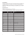
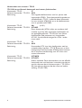
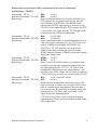
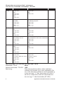
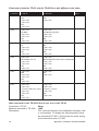
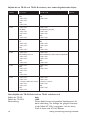
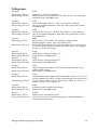
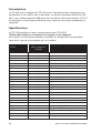
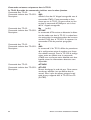
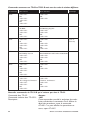
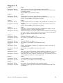
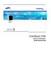
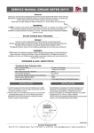
Galvanic
Isolation
Transient
Protection
Balanced
Transmission
CE
Approved
Appendix till installationsmanual
6178-2103
Appendix to installation manual
6178-2203
Anhang zur Bedienungsanleitung
6178-2303
Annexe au manuel d’installation
6178-2491
www.westermo.se
© Westermo Teleindustri AB • 2001 • REV. A
B
2
3
D
T
Introduktion
TD-32 B är en ersättare till den ”gamla” TD-32. Det finns dock vissa små skillnader melllan de båda produkterna som är beskrivna i detta dokument. Installationsmanualen
(6178-2103) är giltig förutom de undantag som står i detta appendix. TD-32 B är Europa
godkänd och kan således användas i hela Europa. Lands specifika varianter av TD-32 B
existerar inte.
Specifikationer
TD-32 B har samma specifikationer som TD-32 EU.
Tabell över kommandon och S-register vars funktion skiljer sig från vad manualen beskriver. För en mer detaljerad beskrivning av skillnaderna, se beskrivningarna nedan.
Kommandon i TD-32
%Dn
\Gn
\Ln
Yn
\F
Nn
\S
&Bn
&Kn
&Tn
ATI2
ATI3
ATI5
ATI6
ATI7
ATI9
S-18
S-19
S-20
S-24
S-32
S-33
S-37
S-39
S-82
2
Sida i manualen
6178-2103 (SE)
19
21
24
33
21
25
29
16
22
30
22
22
22
22
22
22
38
38
38
40
42
42
42
43
44
Beskrivning
Inställning av mottagarns känslighet
Flödeskontroll mellan modem
MNP block eller teckenström
Lång ”space” nedkoppling
Visa lagrade nummer
Automatmod
Visa aktiv konfigurering
Uppringning på DTR
Flödeskontroll
Test och kontroll
Identifikationsrapport
Identifikationsrapport
Identifikationsrapport
Identifikationsrapport
Identifikationsrapport
Identifikationsrapport
Testtimer
Autosync parametrar
Autosync HDLC adress eller Sync
Mottagarens nedkopplingsnivå
XON tecken
XOFF tecken
Bit mappat register
Bit mappat register
Break kontroll för LAPM anslutningar
Appendix till installationsmanual 6178-2103
AT –kommandon
Skillnaderna bland AT-kommandon kan delas in i fem grupper:
• Kommandon som existerar i TD-32 men inte i TD-32 B.
• Kommandon som existerar i TD-32 men inte i TD-32 B men som har ett liknande
kommando i TD-32 B med samma funktonalitet.
• Kommandon som existerar både i varianterna men som har annorlunda funktonalitet i
TD-32 B.
• Kommandon som existerar både i varianterna men som har annorlunda resultatkoder i
TD-32 B.
• Nya kommandon i TD32 B som inte finns med i TD-32.
Kommandon som existerar i TD-32 men inte i TD-32 B
Kommando i TD-32:
%Dn
(n=0,1)
Relevant kommando i TD-32 B: Inget
Beskrivning:
Ställer in minsta mottagen signal nivå innan nedkoppling.
Default värdet är –43 dBm. Värdet sparas i S-register
24 (se S24 nedan). Nedkopplingsnivån kan inte ställas in
i TD-32 B. Används aldrig eller väldigt sällan.
Kommando i TD-32:
\Gn
(n=0,1)
Relevant kommando i TD-32 B: Inget
Beskrivning:
Flödeskontroll mellan modem. Används endast i icke felkorrigerande moder. Används aldrig eller väldigt sällan.
Kommando i TD-32:
\Ln
(n=0,1)
Relevant kommando i TD-32 B: Inget
Beskrivning:
MNP block eller teckenström. Kontrollerar om MNP
protokollet skall använda block eller teckenström
överföring vid uppkoppling. Teckenström överföring är
grundvärdet vid MNP uppkoppling. Används aldrig eller
väldigt sällan.
Kommando i TD-32:
Yn
(n=0,1)
Relevant kommando i TD-32 B: Inget
Beskrivning:
Lång ”space” nedkoppling. Vid grundinställning är funktionen avstängd. Används aldrig eller väldigt sällan.
Appendix till installationsmanual 6178-2103
3
Kommandon som existerar i TD-32.
TD-32 B har ett liknande kommando med samma funktionalitet.
Kommando i TD-32:
\F
Relevant kommando i TD-32 B: &V0
Beskrivning:
Visar lagrade telefonnummer som har sparats med
kommandot AT&Zn. Detta kommando fungerade inte
tillfredställande i TD-32. I stället för detta kommando
kan man använda AT&V0 för att se de telefonnummer
som är sparade med AT&Zn.
Kommando i TD-32:
Nn
(n=0,1)
Relevant kommando i TD-32 B: AT+MS
Beskrivning:
Detta kommando (ATNn) väljer om modemet skall
använda sig av fast eller automatisk linjehastighet vid
ett uppkopplingsförsök. I TD-32 B får man samma
funktionalitet med parameter två i kommandot
AT+MS. Se också beskrivningen för ATNn i under
nästa rubrik.
Kommando i TD-32:
\S
Relevant kommando i TD-32 B: &V0
Beskrivning:
Kommandot AT\S visar aktiv konfiguration med ett
användarvänligt interface. I TD-32 B kan man se aktiv
konfiguration med kommadot AT&V0. Detta kommando är inte lika användarvänligt som AT\S men visar
samma information
Kommando i TD-32:
AT*NCK
Relevant kommando i TD-32 B: AT+GCI
Beskrivning:
Ändrar landskod. Detta kommando är inte ett officiellt
kommando som står beskrivet i manualen men det tas
upp här eftersom det är frekvent använt. I TD-32 B är
det inte relevant eftersom det bara finns en landsinställning: FD (EU-TBR)
4
Appendix till installationsmanual 6178-2103
Kommandon som existerar både i varianterna men som har annorlunda
funktionalitet i TD-32 B
Kommando i TD-32:
&Bn
(n=0,1)
Relevant kommando i TD-32 B: &Bn
(n=0,1)
Beskrivning:
Detta kommando tillåter att man kan använda sig av
DTR-signalen för att göra en uppringning. Men om
man använder sig av AT&D3 i kombination med
kommandot för DTR uppringning så återstartar inte
TD-32 B vid en negativ flank på DTR signalen (se ATZ
– mjuk reset) utan lägger bara på. TD-32 lägger både
på och återstartar vid samma förfarande
Kommando i TD-32:
&Kn
(n=0,3,4,5,6)
Relevant kommando i TD-32 B: &Kn
(n=0,3,4,5)
Beskrivning:
Detta kommando ställer in önskad flödeskontroll. Det
enda som skiljer modemen åt är att i TD-32 kan man
ställa in AT&K6 (använd både XON/XOFF och
RTS/CTS). I TD-32 B existerar inte alternativet
AT&K6. Alla andra inställningar med kommadot
AT&Kn fungerar likadant. AT&K6 kommandot används
aldrig eller väldigt sällan.
Kommando i TD-32:
ATNn
(n=0,1)
Relevant kommando i TD-32 B: ATNn
(n=1)
Beskrivning:
Detta kommando (ATNn) väljer om modemet skall
använda sig av fast eller automatisk linjehastighet vid
ett uppkopplingsförsök i TD-32. I TD-32 B är kommandot bara implementerat för kompatibilitets skäl
och då är bara ATN1 tillåtet. För att ställa in automod
i TD-32 B ska man använda sig av kommandot AT+MS.
Kommando i TD-32:
&Tn
(n=0,1,2,3,4,5,6,7 and 8)
Relevant kommando i TD-32 B: &Tn
(n=0,1)
Beskrivning:
Detta kommando genomför olika tester enligt V.54
loop 2 och loop 3. Loop 2 kan antingen vara en lokal
eller en remote digital återkopplings test och loop 3
kan antingen vara en lokal eller en remote analog återkopplings test. I TD-32 är loop 2 och loop 3 samt
några variationer implementerade.
I TD-32 B är bara loop 3 med analog återkoppling
implementerad. Dessa test kommandon används aldrig
eller väldigt sällan.
Appendix till installationsmanual 6178-2103
5
Kommandon som existerar både i varianterna
men som har annorlunda resultatkoder i TD-32 B.
Kommando
I TD-32
I TD-32 B
Note.
ATI2
<CR><LF>
OK
<CR><LF>
<CR><LF>
OK
<CR><LF>
<CR><LF>
OK
<CR><LF>
ATI3
<CR><LF>
V2.400A<CR><LF>
<CR><LF>
OK
<CR><LF>
<CR><LF>
V3.500-V90_2M_DLS
<CR><LF>
<CR><LF>
OK
<CR><LF>
ATI5
<CR><LF>
49
<CR><LF>
<CR><LF>
OK
<CR><LF>
<CR><LF>
FD
<CR><LF>
<CR><LF>
OK
<CR><LF>
ATI6
<CR><LF>
RCV144Dpi Rev CA
<CR><LF>
<CR><LF>
OK
<CR><LF>
<CR><LF>
RCV336DPF-PLL L8571A Rev 43.06/43.06
<CR><LF>
<CR><LF>
OK
<CR><LF>
ATI7
<CR><LF>
000
<CR><LF>
<CR><LF>
OK
<CR><LF>
<CR><LF>
OK
<CR><LF>
ATI9
<CR><LF>
<CR><LF>
” firmware build time stamp”
<CR><LF>
<CR><LF>
OK
<CR><LF>
<CR><LF>
<CR><LF>
”firmware revision”
<CR><LF>
OK
<CR><LF>
(se nedan)
Nya kommadon i TD-32 B som inte finns med i TD-32
Kommando i TD-32:
None
Relevant kommando i TD-32 B: +MS
Beskrivning:
Detta kommando kontrollerar vilken modulation
modemet skall använda sig av vid en uppkoppling. För
att se vilka alternativa parametrar man kan använda sig
av kan man ange ”=?” efter kommandot (AT+MS=?)
och för att se det aktiva värde som kommandot har
kan man ange ”?” efter kommandot (AT+MS?).
6
Appendix till installationsmanual 6178-2103
S-register
S-register:
Beskrivning TD-32:
Beskrivning TD-32 B:
S-18
Används som test timer för test kommandona AT&Tn.
Används inte. Test kommandona i TD-32 B avbryts med escape sekvens
(+++). Returnerar 000 vid förfrågan om värde.
S-register:
Beskrivning TD-32:
Beskrivning TD-32 B:
S-19
Autosync parametrar – ej ändringsbart för användaren.
Används för bakåt kompatibilitet. Inget värde kan skrivas till registret,
Returnerar 000 vid förfrågan om värde.
S-register:
Beskrivning TD-32:
Beskrivning TD-32 B:
S-20
Autosynk HDLC adress/BSC synk – ej ändringsbart för användaren.
Används för bakåt kompatibilitet. Inget värde kan skrivas till registret,
Returnerar 000 vid förfrågan om värde.
S-register:
Beskrivning TD-32:
Beskrivning TD-32 B:
S-24
Används för mottagarens nedkopplingsnivå om kommandot AT%D1 är
satt.
Används som ”Sleep inactivity timer”. Om registret är satt till något
annat än 0 och modemet befinner sig i normal mod, väntar modemet i
det antal sekunder som är specificerat med S24 innan modemet går över
till ”Sleep mode”. Grundvärdet är 000.
S-register:
Beskrivning TD-32:
Beskrivning TD-32 B:
S-32
XON tecken. Grundvärde: 1710
Används inte. Returnerar 000 vid förfrågan om värde.
S-register:
Beskrivning TD-32:
Beskrivning TD-32 B:
S-33
XOFF tecken. Grundvärde: 1910
Används inte. Returnerar 000 vid förfrågan om värde.
S-register:
Beskrivning TD-32:
S-37
Önskad linjehastighet. Motsvarar det värde som man ger tillsammans
med kommandot ATFn
Används inte. Returnerar 000 vid förfrågan om värde.
Beskrivning TD-32 B:
S-register:
Beskrivning TD-32:
Beskrivning TD-32 B:
S-39
Flödeskontroll, bit mappat register bit 0-2. Accepterar värdena 0, 3, 4, 5
och 6.
Flödeskontroll, bit mappat register bit 0-2. Accepterar värdena 0, 3, 4
och 5. Värdet 6 accepteras ej.
S-register:
S-82
Beskrivning TD-32:
Beskrivning TD-32 B:
Break kontroll för LAPM anslutningar.
Används inte. Returnerar 000 vid förfrågan om värde.
S-register:
S-210
Beskrivning TD-32:
Beskrivning TD-32 B:
Används inte. Returnerar ERROR vid förfrågan om värde.
Ställer in området för tillåtet V.34 symbol hastigheter. Kontrollerar
asymmetriska hastigheter.
Appendix till installationsmanual 6178-2103
7
Introduction
The TD-32 B is a replacement for the “old” TD-32. However, some minor changes are
identified and described in this document.. The original installation manual (6178-2203) is
valid except for the differences described in this appendix. The TD-32 B has no country
specific models, only a pan-European approved version.
Specifications
The TD-32 B has the same specifications as the TD-32 EU.
Short form table of commands and s-registers that differs in any way.
For a more detailed description of what differs see the long form description below.
Commands in TD-32
%Dn
\Gn
\Ln
Yn
\F
Nn
\S
&Bn
&Kn
&Tn
ATI2
ATI3
ATI5
ATI6
ATI7
ATI9
S-18
S-19
S-20
S-24
S-32
S-33
S-37
S-39
S-82
8
Page in manual
6178-2203 (ENG)
19
21
24
33
21
25
29
16
22
30
22
22
22
22
22
22
38
38
38
40
42
42
42
43
44
Description
Setting the sensitivity of receiver
Modem-to-modem flow control
MNP block or stream mode
Long space disconnect
Display stored numbers
Automode
Report active configuration
DTR dial option
Flow control
Test and diagnostics
Identification report
Identification report
Identification report
Identification report
Identification report
Identification report
Test timer
Autosync bit mapped options
Autosync HDLC address or Sync character
Receiver disconnect level
XON character
XOFF character
Bit mapped register
Bit mapped register
Break control for LAPM connections
Appendix to installation manual 6178-2203
AT –commands
The differences in command mode can be divided in four groups:
• Commands that exists in the TD-32 but do not exist in the TD-32 B
• Commands that exists in the TD-32 but not in the TD-32 B but have a similar
command in the TD-32 B with the same functionality
• Commands that exists in both the TD-32 and the TD-32 B but have a different functionality in the TD-32 B.
• Commands that exists in both the TD-32 and the TD-32 B but have different result
codes in the TD-32 B
• New commands in the TD-32 B that do not exist in the TD-32
Commands that exists in the TD-32 but do not exist in the TD32 B.
Command in TD-32:
%Dn
(n=0,1)
Relevant command in TD-32 B: None
Description:
Sets the minimum level of received signal before disconnection. The default value is -43 dBm).
The value is stored in S-register 24 (see S24 below).
The disconnect level can not be set in TD-32 B.
Never or extremely rarely used.
Command in TD-32:
Relevant command in TD-32 B:
Description:
\Gn
(n=0,1)
None
Modem to modem flow control. Only valid non-error
correction modes. Never or extremely rarely used.
Command in TD-32:
Relevant command in TD-32 B:
Description:
\Ln
(n=0,1)
None
MNP block or stream mode select. At connection time
this command controls the selection between block
and stream mode in MNP connections. Default is
stream mode for MNP connections.
Never or extremely rarely used.
Command in TD-32:
Relevant command in TD-32 B:
Description:
Yn
(n=0,1)
None
Long space disconnect. Default is disabled.
Never or extremely rarely used.
Appendix to installation manual 6178-2203
9
Commands only in the TD-32.
TD-32 B have similar commands with the same functionality.
Command in TD-32:
\F
Relevant command in TD-32 B: &V0
Description:
Display telephone directory entries saved by AT&Zn.
This command didn’t work in the TD-32. Instead of
this command one can use the AT&V0 to see the
saved telephone numbers.
Command in TD-32:
Relevant command in TD-32 B:
Description:
Nn
(n=0,1)
AT+MS
The ATNn command in the TD-32 enables/disables
automode detection. The same functionality can be
found in the second parameter of the AT+MS
command in the TD-32 B. See also the ATNn
command in the next section.
Command in TD-32:
Relevant command in TD-32 B:
Description:
\S
&V0
The \S command in the TD-32 displays current
modem settings in a user friendly interface.
The current settings can be viewed with the
command AT&V0. This command is not as user
friendly as the AT\S but still all information needed
can be found.
Command in TD-32:
Relevant command in TD-32 B:
Description:
AT*NCK
AT+GCI
Change country code. This is not an official command
described in the manual. It has no relevance since only
country code supported in TD32 B is FD (EU-TBR).
10
Appendix to installation manual 6178-2203
Commands present in the TD-32 and in the TD-32 B but with different functionality.
Command in TD-32:
Relevant command in TD-32 B:
Description:
&Bn
(n=0,1)
&Bn
(n=0,1)
Enables DTR dialing but when AT&D3 is used together
with &B1, the TD-32 B does not restart as described
under the AT&D3 command in the TD32 manual, it
just goes on hook.
Command in TD-32:
Relevant command in TD-32 B:
Description:
&Kn
(n=0,3,4,5,6)
&Kn
(n=0,3,4,5)
Command to set the DTE flow control. The only thing
that is different in the TD-32 B is the AT&K6 commmand option which means that both XON/XOFF and
RTS/CTS flow control is used. All other options in this
command are the same. This command option is never
or extremely rarely used.
Command in TD-32:
Relevant command in TD-32 B:
Description:
ATNn
(n=0,1)
ATNn
(n=1)
Enables/disables automode detection in TD-32. In TD32 B it is only implemented for compatibility reasons
and only ATN1 is valid. In TD-32 B, use the automode
settings implemented with AT+MS instead.
Command in TD-32:
Relevant command in TD-32 B:
Description:
&Tn
(n=0,1,2,3,4,5,6,7 and 8)
&Tn
(n=0,1)
Test commands according to V.54 loop 2 and loop 3.
Loop 2 is either a local or remote digital loopback test
and loop 3 is either a local or remote analogue loopback test.
In the TD-32, loop 2, loop 3 and some variations of
the two loops are implemented. In TD-32 B only loop
3 local analogue loopback test is implemented.
The test commands are never or extremely rarely
used.
Appendix to installation manual 6178-2203
11
Commands in both the TD-32 and the TD-32 B but with different result codes
Command
In TD-32
In TD-32 B
Note.
ATI2
<CR><LF>
OK
<CR><LF>
<CR><LF>
OK
<CR><LF>
<CR><LF>
OK
<CR><LF>
ATI3
<CR><LF>
V2.400A<CR><LF>
<CR><LF>
OK
<CR><LF>
<CR><LF>
V3.500-V90_2M_DLS
<CR><LF>
<CR><LF>
OK
<CR><LF>
ATI5
<CR><LF>
49
<CR><LF>
<CR><LF>
OK
<CR><LF>
<CR><LF>
FD
<CR><LF>
<CR><LF>
OK
<CR><LF>
ATI6
<CR><LF>
RCV144Dpi Rev CA
<CR><LF>
<CR><LF>
OK
<CR><LF>
<CR><LF>
RCV336DPF-PLL L8571A Rev 43.06/43.06
<CR><LF>
<CR><LF>
OK
<CR><LF>
ATI7
<CR><LF>
000
<CR><LF>
<CR><LF>
OK
<CR><LF>
<CR><LF>
OK
<CR><LF>
ATI9
<CR><LF>
<CR><LF>
” firmware build time stamp”
<CR><LF>
<CR><LF>
OK
<CR><LF>
<CR><LF>
<CR><LF>
”firmware revision”
<CR><LF>
OK
<CR><LF>
(see below)
New commands in the TD-32 B that do not exist in the TD-32
Command in TD-32:
Relevant command in TD-32 B:
Description:
12
None
+MS
This command controls the modulation technique used
in a connection. To display the valid parameters enter
the command AT+MS=?. And to see the active setting
of the command enter AT+MS?
Appendix to installation manual 6178-2203
S-registers
S-register:
Description TD-32:
Description TD-32 B:
S-18
Used as a timer for the test commands &Tn.
Not used. The test commands in TD-32 B is terminated via the escape
sequence. Returns 000 when accessed.
S-register:
Description TD-32:
Description TD-32 B:
S-19
Autosync bitmapped options – not editable by user.
For backwards compatibility only. No value can be written. Returns 000
when accessed.
S-register:
Description TD-32:
Description TD-32 B:
S-20
Autosync HDLC address or BSC sync character – not editable by user.
For backwards compatibility only. No value can be written. Returns 000
when accessed.
S-register:
Description TD-32:
S-24
Used to hold the value of the lowest acceptable received line signal
when using the %D1 command.
Used as the Sleep Inactivity timer. When in normal mode of the TD-32
B the modem waits the number of seconds specified by this register
before it enter sleep mode.
Description TD-32 B:
S-register:
Description TD-32:
Description TD-32 B:
S-32
XON character. Default: 1710
Not used. Returns 000 when accessed.
S-register:
Description TD-32:
Description TD-32 B:
S-33
XOFF character. Default 1910
Not used. Returns 000 when accessed.
S-register:
Description TD-32:
S-37
Desired line connection speed. Corresponds to the value given by the
command ATFn.
Not used. Returns 000 when accessed.
Description TD-32 B:
S-register:
Description TD-32:
Description TD-32 B:
S-39
Flow control bit mapped options status bit 0-2. Values 0,3, 4,5 and 6 is
accepted. The value 6 indicates that both methods are used.
Flow control bit mapped options status bit 0-2. Values 0, 3, 4 and 5 is
accepted. Value 6 is not supported.
S-register:
S-82
Description TD-32:
Description TD-32 B:
Break control for LAPM connections.
Not used. Returns 000 when accessed.
S-register:
S-210
Description TD-32:
Description TD-32 B:
Not used. Returns ERROR when accessed.
Sets the range of V.34 symbol rates. Enables/disables asymmetric rates.
Appendix to installation manual 6178-2203
13
Einleitung
Das TD-32 B ist ein ersatz für das “alte” TD-32. Dadurch haben sich kleine Änderungen
ergeben, welche in diesem Dokument beschrieben sind. Die original Bedienungsanleitung
(??6178-2203) gilt weiterhin, außer für die nachfolgend aufgeführten Punkte. Das TD-32 B
ist nur als Europa Version erhältlich.
Technische Daten
Das TD-32 B besitzt die selben Eigenschaften wie das TD-32 EU.
Kurzübersicht der geänderten Befehle und S-Register
Eine ausführliche Beschreibung folgt in diesem Dokument.
Befehl des TD-32
Seite in Anleitung
6178-2303 (DE)
%Dn
\Gn
\Ln
Yn
\F
Nn
\S
&Bn
&Kn
&Tn
ATI2
ATI3
ATI5
ATI6
ATI7
ATI9
S-18
S-19
S-20
19
21
24
33
21
25
29
16
22
30
22
22
22
22
22
22
38
38
38
S-24
S-32
S-33
S-37
S-39
S-82
40
42
42
42
43
44
14
Beschreibung
Empfindlichkeit des Empfängers
Modem-zu-modem Datenflußsteuerung
MNP Block oder Datenstron Modus
Langes Space
Anzeige gespeicherter Nummern
Automode
Anzeige der aktiven Konfiguration
DTR Wähloption
Datenflussteuerung
Test und Diagnose
Identifikations Anzeige
Identifikations Anzeige
Identifikations Anzeige
Identifikations Anzeige
Identifikations Anzeige
Identifikations Anzeige
Zeitgeber für Tests
Automatisch Synchronisation
Auto. Synchronisation HDLC
Adresse oder sync. Zeichen
Abbruchpegel für Empfang
XON Zeichen
XOFF Zeichen
Bit mapped Register
Bit mapped Register
Breaksteuerung für LAPM Verbindungen
Anhang zur Bedienungsanleitung 6178-2303
AT – Befehle
Die Unterschiede im Befehlsmodus können in vier Gruppen aufgeteilt werden:
• Befehle des TD-32 die nicht im TD-32 B enthalten sind
• Befehle des TD-32 die nicht im TD-32 B enthalten sind, aber es gleiche Befehle im TD32 B mit der selben Funktionalität gibt
• Befehle die im TD-32 und TD-32 B existieren, aber andere Funktionen aufweisen.
• Befehle die im TD-32 und TD-32 B existieren, aber andere Ergebnisscodes liefern
• Neue Befehle des TD-32 B die nicht im TD-32 enthalten sind
Befehle des TD-32 die nicht im TD-32 B enthalten sind.
Befehl des TD-32:
%Dn
(n=0,1)
Befehl des TD-32 B:
kein
Beschreibung:
Bestimmt den minimalen Empfangspegel, bevor die
Verbindung unterbrochen wird (Werkseinstellung -43
dBm). Der Wert wird im S-Register 24 (siehe S24)
gespeichert. Dieser Pegel kann im TD-32 B nicht
gesetzt werden. Niemals oder nur sehr selten benutzt.
Befehl des TD-32:
Befehl des TD-32 B:
Beschreibung:
\Gn
(n=0,1)
kein
Modem zu Modem Datenflussteuerung.
Nur für Verbindungen ohne Fehlerkorrektur.
Niemals oder nur sehr selten benutzt.
Befehl des TD-32:
Befehl des TD-32 B:
Beschreibung:
\Ln
(n=0,1)
kein
MNP Block oder Datenstrom Modus. Beim
Verbindungsaufbau setzt dieser Befehl ob Block oder
Datenstrom Modus bei MNP Verbindungen benutzt
wird. Werkseinstellung ist Datenstrom Modus bei
MNP verbindungen. Niemals oder nur sehr selten
benutzt.
Befehl des TD-32:
Befehl des TD-32 B:
Beschreibung:
Yn
(n=0,1)
kein
Trennen bei langem Space Signal. Werkseinstellung
deaktiviert. Niemals oder nur sehr selten benutzt.
Anhang zur Bedienungsanleitung 6178-2303
15
Befehle des TD-32 die nicht im TD-32 B enthalten sind, aber es gleiche Befehle im
TD-32 B mit der selben Funktionalität gibt
Befehl des TD-32:
\F
Befehl des TD-32 B:
&V0
Beschreibung:
Anzeige der durch AT&Zn eingetragenen Telefonnummern. Dieser Befehl funktionierte nicht im TD-32.
Anstatt dieses Befehls kann der AT&V0 eingesetzt
werden.
Befehl des TD-32:
Befehl des TD-32 B:
Beschreibung:
Nn
(n=0,1)
AT+MS
Der ATNn Befehl des TD-32 aktivierte/deaktivierte die
Automode Erkennung. Dieselbe Funktionalität kann
mit dem zweiten Parameter des AT+MS Befehls des
TD-32 B erreicht werden. Siehe auch ATNn Befehl im
nächsten Abschnitt.
Befehl des TD-32:
Befehl des TD-32 B:
Beschreibung:
\S
&V0
Der \S Befehl des TD-32 zeigt die aktuelle
Modemeinstellung benutzerfreundlich an. Die aktuelle
Konfiguration kann mit AT&V0 angezeigt werden, ist
aber nicht so benutzerfreundlich, enthält aber alle notwendigen Informationen.
Befehl des TD-32:
Befehl des TD-32 B:
Beschreibung:
AT*NCK
AT+GCI
Ändern der Landeseinstellung. Dies ist ein nicht in der
Anleitung beschriebener Befehl. Nicht relevant, da nur
Europa im TD32 B unterstützt wird (FD = EU-TBR).
16
Anhang zur Bedienungsanleitung 6178-2303
Befehle die im TD-32 und TD-32 B existieren, aber andere Funktionen aufweisen.
Befehl des TD-32:
Befehl des TD-32 B:
Beschreibung:
&Bn
(n=0,1)
&Bn
(n=0,1)
Aktiviert DTR Wahl, aber wenn AT&D3 und AT&B1
benutzt wird, so fährt das TD-32 B nicht reset, wie
unter AT&D3 beschrieben, sondern legt nur auf.
Befehl des TD-32:
Befehl des TD-32 B:
Beschreibung:
&Kn
(n=0,3,4,5,6)
&Kn
(n=0,3,4,5)
Befehl zum setzen der Datenflussteuerung zur DEE.
Der einzige Unterschied des TD-32 B ist die AT&K6
Option welche XON/XOFF und RTS/CTS Steuerung
setzt. Alle anderen optionen sind gleich Die Option
wird niemals oder nur sehr selten benutzt
Befehl des TD-32:
Befehl des TD-32 B:
Beschreibung:
ATNn
(n=0,1)
ATNn
(n=1)
Aktiviert/deaktiviert Automode Erkennung des TD-32.
Wurde im TD-32 B nur zu kompatibilitäts Zwecken
implementiert, nur ATN1 ist ein gültiger Parameter.
Beim TD-32 B wird der Automode durch AT+MS
gesetzt.
Befehl des TD-32:
Befehl des TD-32 B:
Beschreibung:
&Tn
(n=0,1,2,3,4,5,6,7 and 8)
&Tn
(n=0,1)
Test Befehle nach V.54 loop 2 und loop 3. Loop 2 ist
entweder ein lokaler oder entfernter digitaler loopback Test und loop 3 ist entweder ein lokaler oder
entfernter analoger loopback Test. Im TD-32 sind loop
2, loop 3 und weitere Variationen implementiert. Im
TD-32 B wird nur loop 3, lokaler analoger loopback
Test unterstützt. Wird niemals oder nur sehr selten
benutzt.
Anhang zur Bedienungsanleitung 6178-2303
17
Befehle die im TD-32 und TD-32 B existieren, aber andere Ergebnisscodes liefern
Befehl
Im TD-32
Im TD-32 B
Hinweis
ATI2
<CR><LF>
OK
<CR><LF>
<CR><LF>
OK
<CR><LF>
<CR><LF>
OK
<CR><LF>
ATI3
<CR><LF>
V2.400A<CR><LF>
<CR><LF>
OK
<CR><LF>
<CR><LF>
V3.500-V90_2M_DLS
<CR><LF>
<CR><LF>
OK
<CR><LF>
ATI5
<CR><LF>
49
<CR><LF>
<CR><LF>
OK
<CR><LF>
<CR><LF>
FD
<CR><LF>
<CR><LF>
OK
<CR><LF>
ATI6
<CR><LF>
RCV144Dpi Rev CA
<CR><LF>
<CR><LF>
OK
<CR><LF>
<CR><LF>
RCV336DPF-PLL L8571A Rev 43.06/43.06
<CR><LF>
<CR><LF>
OK
<CR><LF>
ATI7
<CR><LF>
000
<CR><LF>
<CR><LF>
OK
<CR><LF>
<CR><LF>
OK
<CR><LF>
ATI9
<CR><LF>
<CR><LF>
” firmware build time stamp”
<CR><LF>
<CR><LF>
OK
<CR><LF>
<CR><LF>
<CR><LF>
”firmware revision”
<CR><LF>
OK
<CR><LF>
(siehe unten)
Neue Befehle des TD-32 B die nicht im TD-32 enthalten sind
Befehl des TD-32:
Befehl des TD-32 B:
Beschreibung:
18
kein
+MS
Dieser Befehl steuert die gewählte Modulationsart für
diese Verbindung. Zur Anzeige der gültigen Parameter
ist der Befehl AT+MS=? einzugeben. Um das aktive
Profil zu lesen wird AT+MS? Benutzt.
Anhang zur Bedienungsanleitung 6178-2303
S-Registers
S-Register:
Beschreibung TD-32:
Beschreibung TD-32 B:
S-18
Zeitgeber für die &Tn Testbefehle.
Nicht benutzt. Die Testbefehle des TD-32 B werden durch die Escape
Sequenz beendet. Gibt 000 zurück.
S-Register:
Beschreibung TD-32:
Beschreibung TD-32 B:
S-19
Autosync Bitmapped Option – nicht vom Anwender editierbar.
Nur zu Kompatibilitätszwecken. Kein Wert kann geschrieben werden.
Gibt 000 zurück.
S-Register:
Beschreibung TD-32:
Beschreibung TD-32 B:
S-20
Autosync HDLC Adresse oder BSC Sync Zeichen – nicht editierbar.
Nur zu Kompatibilitätszwecken. Kein Wert kann geschrieben werden.
Gibt 000 zurück.
S-Register:
Beschreibung TD-32:
S-24
Wird benutzt, um den Wert des niedrigsten akzeptierbaren
Empafangspegel zu setzen, wenn %D1 benutzt wird.
Benutzt als Sleep Inactivity Timer. Bei Normalbetrieb des TD-32 B wartet das Modem die Anzahl der Sekunden, gesetzt durch dieses Register,
ab bevor es in Sleep Mode geht.
Beschreibung TD-32 B:
S-Register:
Beschreibung TD-32:
Beschreibung TD-32 B:
S-32
XON Zeichen. Werkseinstellung: 1710
Nicht benutzt. Gibt 000 zurück.
S-Register:
Beschreibung TD-32:
Beschreibung TD-32 B:
S-33
XOFF Zeichen. Werkseinstellung 1910
Nicht benutzt. Gibt 000 zurück.
S-Register:
Beschreibung TD-32:
S-37
Verbindungsgeschwindigkeit auf der Leitung. Bezieht sich auf den mit
ATFn gesetzten Wert.
Nicht benutzt. Gibt 000 zurück.
Beschreibung TD-32 B:
S-Register:
Beschreibung TD-32:
Beschreibung TD-32 B:
S-39
Datenflussteuerung Bit mapped Option Statusbit 0-2. Wert 0, 3, 4, 5 und 6
werden akzeptiert. Der Wert 6 zeight die Anwendung beider Optionen an.
Flow control bit mapped options status bit 0-2. Values 0, 3, 4 and 5 is
accepted. Value 6 is not supported.
S-Register:
S-82
Beschreibung TD-32:
Beschreibung TD-32 B:
Breaksteuerung bei LAPM Verbindungen
Nicht benutzt. Gibt 000 zurück.
S-Register:
S-210
Beschreibung TD-32:
Beschreibung TD-32 B:
Nicht benutzt. Gibt ERROR zurück.
Setzt die Grenzen der V.34 Übertragungsraten. Aktiviert/deaktiviert
asymmetrische Datenraten.
Anhang zur Bedienungsanleitung 6178-2303
19
Introduction
Le TD-32 B est le remplaçant du TD-32 existant. Cependant certains changements ont
été identifiés et sont décrits dans ce document. Le manuel d’installation d’origine (61782491) reste valable excepté les différences qui sont décrites dans cette annexe. Le TD-32
B n’existe pas en version personnalisée par pays. Seule une version pan-européenne est
disponible.
Spécifications
Le TD-32 B possède les mêmes caractéristiques que le TD-32 EU.
Tableau Résumant les commandes et registres S qui changent
Pour obtenir une description détaillée ou connaître les changements correspondants,
merci de se reporter au paragraphe qui suit le tableau.
Commandes du
TD-32
%Dn
\Gn
\Ln
Yn
\F
Nn
\S
&Bn
&Kn
&Tn
ATI2
ATI3
ATI5
ATI6
ATI7
ATI9
S-18
S-19
S-20
S-24
S-32
S-33
S-37
S-39
S-82
20
Page correspondante
dans le manuel réf:
6178-2491
19
21
24
33
21
25
29
16
22
30
22
22
22
22
22
22
38
38
38
40
42
42
42
43
44
Description
Configuration de la sensibilité du récepteur
Contrôle de flux modem à modem
Sélection du mode bloc ou mode stream MNP
Déconnexion sur grand espace
Affiche la liste des N° d’appels sauvegardés
Mode Auto
Affiche la configuration active
Option numérotation par DTR
Contrôle de flux
Test et diagnostics
Rapport d’identification
Rapport d’identification
Rapport d’identification
Rapport d’identification
Rapport d’identification
Rapport d’identification
Test timer
Organisation du bit AutoSync
Adresse caractère AutoSync HDLC ou SYNC
Niveau de déconnexion récepteur
Caractère XON
Caractère XOFF
Organisation des bits du registre
Organisation des bits du registre
Contrôle Break pour connexion LAPM
Annexe au manuel d’installation 6178-2491
Commandes AT
Les changements concernant les différentes commandes sont répartis en quatre
groupes :
• Commandes existantes dans le TD-32 mais qui n’existent plus dans le TD-32 B
• Commandes existantes dans le TD-32 et qui ont disparu dans le TD-32 B mais qui
sont remplacées par d’autres commandes similaires avec les mêmes fonctionnalités.
• Commandes existantes dans le TD-32 et TD-32 B mais avec des fonctions différentes
dans le TD-32 B
• Commandes existantes dans le TD-32 et TD-32 B mais avec des codes de résultats
différents dans le TD-32 B
• Nouvelles commandes dans le TD-32 B et qui n’existent pas dans le TD-32.
Commandes existantes dans le TD-32 et qui n’existent pas dans le TD-32 B.
Commande dans TD-32 :
%Dn (n=0,1)
Commande similaire dans TD-32 B : Aucune
Description :
Définit la déconnexion du modem lorsque le niveau du signal de réception est inférieur au seuil
nominal (Valeur par défaut : -43dBm). La valeur est
stockée dans le registre S-24.(voir S-24 ci-dessous).
Le niveau de déconnexion n’est pas configurable
dans le TD-32 B. Jamais ou rarement utilisé.
Commande dans TD-32 :
\Gn
(n=0,1)
Commande similaire dans TD-32 B : Aucune
Description :
Contrôle de flux modem à modem. Uniquement
actif en mode de correction sans erreur. Jamais ou
rarement utilisé.
Commande dans TD-32 :
\Ln
(n=0,1)
Commande similaire dans TD-32 B : Aucune
Description :
Sélection du mode bloc MNP ou mode stream. Au
moment de la connexion, cette commande contrôle la sélection entre le mode block et le mode
stream dans les connexions MNP. Par défaut, le
mode stream est activé pour les connexions MNP.
Jamais ou rarement utilisé.
Commande dans TD-32 :
Yn
(n=0,1)
Commande similaire dans TD-32 B : Aucune
Description :
Déconnexion sur grand espace. Désactivé par
défaut. Jamais ou rarement utilisé.
Annexe au manuel d’installation 6178-2491
21
Commandes existantes uniquement dans le TD-32.
Le TD-32 B possède des commandes similaires avec la même fonction.
Commande dans TD-32 :
\F
Commande similaire dans TD-32 B : &V0
Description :
Affiche la liste des N° d’appel sauvegardés avec la
commande AT&Zn. Cette commande ne fonctionne pas sur le TD-32. On peut utiliser en lieu
et place la commande AT&V0 pour voir la liste
des N° d’appel sauvegardés.
Commande dans TD-32 :
Nn
(n=0,1)
Commande similaire dans TD-32 B : AT+MS
Description :
La commande ATNn active ou désactive la détection du mode auto dans le TD-32. La même fonction existe dans le second paramètre de la commmande AT+MS dans le TD-32 B. Se reporter à la
commande ATNn du prochain paragraphe.
Commande dans TD-32 :
\S
Commande similaire dans TD-32 B : &V0
Description :
La commande \S du TD-32, affiche les paramètres
de la configuration active du modem sous forme
d’un tableau convivial. Dans le TD-32 B la configuration active est affichée avec la commande
AT&V0 sous une forme moins détaillée mais dans
laquelle toutes les informations nécessaire sont
disponibles.
Commande dans TD-32 :
AT*NCK
Commande similaire dans TD-32 B : AT+GCI
Description :
Permet de changer le code du pays. Cette commmande non officielle n’est pas décrite dans le
manuel. Elle n’a plus de rapport puisque le seul
code du pays supporté dans le TD-32 B est FD
(EU-TBR).
22
Annexe au manuel d’installation 6178-2491
Commandes existantes dans le TD-32 et le TD-32 B mais avec des fonctions différentes.
Commande dans TD-32 :
&Bn
(n=0,1)
Commande similaire dans TD-32 B : &Bn
(n=0,1)
Description :
Active la numérotation par DTR mais lorsque
AT&D3 est utilisé conjointement avec &B1. Le
TD-32 B ne se réinitialise pas avec AT&D3
comme il est décrit dans le manuel du TD-32. Il
raccroche simplement.
Commande dans TD-32 :
&Kn
(n=0,3,4,5,6)
Commande similaire dans TD-32 B : &Kn
(n=0,3,4,5)
Description :
Cette commande configure le contrôle de flux
DTE. La seule différence avec le TD-32 B concerne L’option AT&K6 (active ensemble le contrôle
de flux XON/XOFF et RTS/CTS). Toutes les
autres options sont identiques. Cette option de
commande n’est jamais ou rarement utilisée.
Commande dans TD-32 :
ATNn (n=0,1)
Commande similaire dans TD-32 B : ATNn (n=1)
Description :
Active ou désactive la détection du mode auto
dans le TD-32. Dans le TD-32 B, cette commande
n’existe que pour des raisons de compatibilité et
seul ATN1 est valide. La configuration du mode
auto dans le TD-32 B est configurable avec la
commande AT+MS.
Commande dans TD-32 :
&Tn
(n=0,1,2,3,4,5,6,7 and 8)
Commande similaire dans TD-32 B : &Tn
(n=0,1)
Description :
Commande de test V.54 boucle 2 et boucle 3. La
boucle 2 peut être un test de bouclage digital local
ou distant et la boucle 3 fait de même mais pour
un test en analogique.Dans le TD-32, la boucle
2,boucle 3 et certaines variations des 2 boucles
sont implémentées. Dans le TD-32 B seule la boucle 3, bouclage analogique local, est supportée. Les
commandes de test ne sont jamais ou rarement
utilisées.
Annexe au manuel d’installation 6178-2491
23
Commandes communes aux TD-32 et TD-32 B mais avec des codes de résultats différents.
Commandes
Dans TD-32
Dans TD-32 B
Remarque
ATI2
<CR><LF>
OK
<CR><LF>
<CR><LF>
OK
<CR><LF>
<CR><LF>
OK
<CR><LF>
ATI3
<CR><LF>
V2.400A<CR><LF>
<CR><LF>
OK
<CR><LF>
<CR><LF>
V3.500-V90_2M_DLS
<CR><LF>
<CR><LF>
OK
<CR><LF>
ATI5
<CR><LF>
49
<CR><LF>
<CR><LF>
OK
<CR><LF>
<CR><LF>
FD
<CR><LF>
<CR><LF>
OK
<CR><LF>
ATI6
<CR><LF>
RCV144Dpi Rev CA
<CR><LF>
<CR><LF>
OK
<CR><LF>
<CR><LF>
RCV336DPF-PLL L8571A Rev 43.06/43.06
<CR><LF>
<CR><LF>
OK
<CR><LF>
ATI7
<CR><LF>
000
<CR><LF>
<CR><LF>
OK
<CR><LF>
<CR><LF>
OK
<CR><LF>
ATI9
<CR><LF>
<CR><LF>
“Horodatage du Firmware”
<CR><LF>
<CR><LF>
OK
<CR><LF>
<CR><LF>
<CR><LF>
“Révision du firmware”
<CR><LF>
OK
<CR><LF>
(voir cidessous)
Nouvelles commandes du TD-32 B qui n’existent pas dans le TD-32
Commande dans TD-32 :
Aucune
Commande similaire dans TD-32 B : +MS
Description :
Cette commande contrôle la technique de modulation utilisée dans la connexion. Pour afficher le
détail des paramètres, taper la commande
AT+MS= ? et pour afficher les paramètres en
cours, taper AT+MS ?
24
Annexe au manuel d’installation 6178-2491
Registres S
Registre S :
Description TD-32 :
Description TD-32 B :
S-18
Utilisé comme timer pour les commandes de test et &Tn.
Non utilisé. Les commandes de test dans le TD-32 B sont achevées par
la séquence escape.
Renvoie 000 à toute demande d’accès .
Registre S :
Description TD-32 :
Description TD-32 B :
S-19
Organisation bit autosync. Non visible par l’utilisateur.
Uniquement pour les compatibilités d’arrière plan. Aucune valeur n’est
inscrite. Renvoie 000 à toute demande d’accès.
Registre S :
Description TD-32 :
S-20
Adresse HDLC autosync ou caractère de sync.BSC. Non visible par l’utilisateur.
Uniquement pour les compatibilités d’arrière plan. Aucune valeur n’est
inscrite. Renvoie 000 à toute demande d’accès.
Description TD-32 B :
Registre S :
Description TD-32 :
Description TD-32 B :
S-24
Utilisé pour stocker la plus faible valeur acceptable du signal de réception ligne lorsque l’on utilise la commande %D1.
Utilisé comme timer de mise en veille d’inactivité. Quand le TD-32 B est
en mode normal, le modem attend durant la période en seconde spécifiée dans ce registre avant de passer en mode veille.
Registre S :
Description TD-32 :
Description TD-32 B :
S-32
Caractère XON. Par défaut : 1710
Non utilisé, renvoie 000 à toute demande d’accès.
Registre S :
Description TD-32 :
Description TD-32 B :
S-33
Caractère XOFF. Par défaut : 1910
Non utilisé, renvoie 000 à toute demande d’accès.
Registre S :
Description TD-32 :
S-37
Vitesse de connexion souhaitée. Correspond à la valeur fournie par la
commande ATFn.
Non utilisé, renvoie 000 à toute demande d’accès.
Description TD-32 B :
Registre S :
Description TD-32 :
Description TD-32 B :
S-39
Statut des options du bit 0-2 du contrôle de flux. Les valeurs 0, 3, 4, 5 et
6 sont acceptées. La valeur 6 indique que les 2 méthodes sont utilisées.
Statut des options du bit 0-2 du contrôle de flux. Les valeurs 0,3,4,5 et 6
sont acceptées. La valeur 6 n’est pas supportée.
Registre S :
S-82
Description TD-32 :
Description TD-32 B :
Contrôle Break pour les connections LAPM.
Non utilisé, renvoie 000 à toute demande d’accès.
Registre S :
S-210
Description TD-32 :
Description TD-32 B :
Non utilisé, renvoie ERROR à toute demande d’accès.
Configure la gamme de vitesse de débit V.34. Active/désactive le débit
asymétrique.
Annexe au manuel d’installation 6178-2491
25
OWN COMMENTS
.....................................................................................................................................................................................................................
.....................................................................................................................................................................................................................
.....................................................................................................................................................................................................................
.....................................................................................................................................................................................................................
.....................................................................................................................................................................................................................
.....................................................................................................................................................................................................................
.....................................................................................................................................................................................................................
.....................................................................................................................................................................................................................
.....................................................................................................................................................................................................................
.....................................................................................................................................................................................................................
.....................................................................................................................................................................................................................
.....................................................................................................................................................................................................................
.....................................................................................................................................................................................................................
.....................................................................................................................................................................................................................
.....................................................................................................................................................................................................................
26
Subsidiaries
Westermo Data Communications Ltd
Unit 14 Talisman Business Centre • Duncan Road
Park Gate, Southampton • SO31 7GA
Phone: +44(0)1489 580 585 • Fax.:+44(0)1489 580586
E-Mail: [email protected] • Web: www.westermo.co.uk
Westermo Data Communications GmbH
Goethestraße 67, 68753 Waghäusel
Tel.: +49(0)7254-95400-0 • Fax.:+49(0)7254-95400-9
E-Mail: [email protected] • Web: www.westermo.de
Westermo Data Communications S.A.R.L.
9 Chemin de Chilly 91160 CHAMPLAN
Tél : +33 1 69 10 21 00 • Fax : +33 1 69 10 21 01
E-mail : [email protected] • Site WEB: www.westermo.fr
Westermo Teleindustri AB have distributors in several
countries, contact us for further information.
01.11 Mälartryck AB, Eskilstuna, Sweden
6178-2103/6178-2203/6178-2303/6178-2403
Westermo Teleindustri AB • SE-640 40 Stora Sundby, Sweden
Phone +46 16 42 80 00 Fax +46 16 42 80 01
E-mail: [email protected] • Westermo Web site: www.westermo.se