1
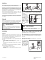
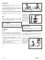
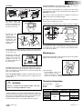
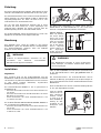
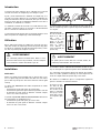
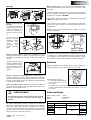
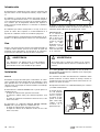
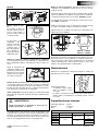
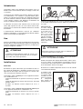
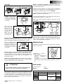
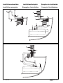
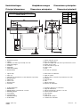
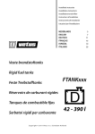
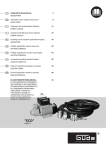
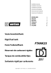
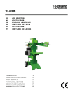
Installatie instructies
Installation instructions
Installationsvorschriften
Instructions d’installation
Instrucciones de instalación
Istruzioni per l’installazione
NEDERLANDS
ENGLISH
DEUTSCH
FRANÇAIS
ESPAÑOL
ITALIANO
2
4
6
8
10
12
Brandstof-overloop
Splash-Stop
Treibstoff-Überlauf
Splash stop pour gas-oil
Rebosadero de carburante
Interruttore di flusso per carburante
C o p y r i g h t © 2 0 0 5 Ve t u s d e n O u d e n n . v. S c h i e d a m H o l l a n d
FS3816
FS5116
FS5119
FS5122
FS5125
Inleiding
De Vetus brandstof-overloop voorkomt dat brandstof uit de tank
via de vuldop overloopt en op het dek terecht komt.
Overlopen van de brandstof kan gebeuren tijdens het vullen als
de tank vrijwel vol is of als de brandstoftank gevuld is met zeer
koude brandstof, uit een ondergrondse tank, terwijl de omgevingstemperatuur van de tank aan boord hoog is. De brandstof
zal dan tijdens het opwarmen uitzetten!
De uit de tank overlopende brandstof wordt in een 2 liter groot
reservoir opgevangen. Dit reservoir zal uiteindelijk via de ontluchtingsleiding in de brandstoftank leeg lopen.
Het schot moet bij voorkeur zodanig schuin staan dat de vulbuis in de brandstof-overloop 10˚ of meer aflopend schuin is
opgesteld.
De werking van de brandstof-overloop wordt sterk verbeterd
indien gebruik wordt gemaakt van een vulpistool met automatische afslag.
FS3816/ FS5116:
Indien een slang van
ø 51 mm wordt aangesloten, dient de
aansluiting
voor
slang ø 38 mm te
worden afgezaagd.
Braam het zaagvlak
goed af. Verwijder
eventueel zaagsel
uit de brandstofoverloop.
Gebruik
Plaats eerst het vulpistool zo ver mogelijk in de interne vulbuis
(door de rubberflappen van de anti-spat mof) van de brandstofoverloop, bedien dan het vulpistool om de tank te vullen.
Afbramen
Afzagen
ø38 (1.5")
ø51 (2")
WAARSCHUWING
Brandstof is schadelijk voor het millieu. Voorkom morsen
van brandstof! Houdt olieabsorberende doeken gereed
als voorzorgsmaatregel!
Installatie
Algemeen
Bepaal een geschikte plaats voor de brandstof-overloop en de
vuldop. De brandstof-overloop is geschikt om te worden toegepast met zowel een in het dek geplaatste vuldop als met een in
een schot (vertikaal vlak) geplaatste vuldop.
De brandstof-overloop FS3816 is alleen toepasbaar in combinatie met:
- de Vetus dekdop voor diesel ø 38 mm
- de Vetus dekdop voor ‘unleaded gasoline’ (benzine) ø 38
mm
- een dekdop met een uitwendige diameter van ø 37,7 mm tot
ø 38,3 mm
De brandstof-overloop FS5116/ FS5119/ FS5122/ FS5125 is
alleen toepasbaar in combinatie met:
- de Vetus dekdop voor diesel ø 51 mm
- een dekdop met een uitwendige diameter van ø 51 mm tot
ø 52,8 mm
2
040402.02
WAARSCHUWING
Plaats de vuldop nooit in een afgesloten ruimte, gemorste
brandstof kan dan in het schip terechtkomen !
Indien als brandstof benzine (in plaats van dieselolie) wordt
toegepast dient de brandstof-overloop in een zeer goed
geventileerde ruimte te worden opgesteld!
De slangaansluitingen van de brandstof-overloop moeten tijdens de montage goed toegankelijk zijn, houdt hier rekening
mee bij het kiezen van de plaats voor de brandstof-overloop en
de vuldop.
Ook voor controle en eventueel onderhoud is een goede toegankelijkheid van belang.
Indien de vuldop in
een vertikaal vlak is
gemonteerd dan
moet het kleine
ontluchtingsgat in
de
anti-spatmof
zich op het laagste
punt bevinden.
Brandstof-overloop
NEDERLANDS
Monteer de ontluchtingsleiding, pas hiervoor een brandstofbestendige slang met een inwendige diameter van 16, 19, 22 of
25 mm toe (afhankelijk van de uitvoering).
Montage
Het eerste stuk ontluchtingsleiding, tevens retourleiding voor de
in de brandstof-overloop opgevangen brandstof, dient van de
tank naar de aansluiting ‘RETURN’ te worden gevoerd.
Het tweede stuk ontluchtingsleiding dient van de aansluiting
‘VENT’ naar de ontluchtingsnippel te worden gevoerd.
Monteer de vuldop. De
slangaansluiting van de
vuldop dient zo kort
mogelijk te zijn, kort
indien noodzakelijk de
slangaansluiting in.
De ontluchtingsleiding dient, vanaf de tank tot aan het geurfilter
of de zwanehals, voortdurend in hoogte oplopend te worden
gemonteerd.
Monteer alle slangverbindingen met 2 RVS slangklemmen!
De brandstof-overloop is aan de
bovenzijde voorzien van een aansluiting voor de
ontluchtingsleiding. Deze aansluiting is circa
200˚ draaibaar.
Monteer de brandstof-overloop met de reeds voorgemonteerde rubbermof en de meegeleverde slangklem op de vuldop.
Gebruik eventueel water of zeep; geen olie.
Ondersteun de brandstofoverloop door de meegeleverde strip aan het dek
of het gangboord vast te
maken. De strip kan
zowel links als rechts aangebracht worden.
Monteer een vulslang tussen de brandstof-overloop en de
tank, pas hiervoor een brandstofbestendige slang met een
inwendige diameter van 38 mm resp. 51 mm toe. Installeer deze
slang zodanig dat zowel de tank als de brandstofoverloop niet
mechanisch worden belast.
Plaats de ontluchtingsnippel, zo hoog mogelijk, boven het
niveau van de brandstof-overloop. Uittrede van brandstof uit de
ontluchting wordt hiermee voorkomen.
WAARSCHUWING
Kies een zodanige plaats voor de ontluchtingsnippel
dat dampen niet in het schip terecht kunnen komen!
Via de ontluchtingsnippel kunnen onaangename geuren vrijkomen. Dit is te voorkomen door het installeren van een actief koolfilter (Vetus geurfilter) in de ontluchtingsleiding. Raadpleeg de
bijbehorende handleiding voor installatie van het Vetus geurfilter.
Het Vetus geurfilter is alleen geschikt voor diesel, niet voor benzine.
Brandstof-overloop
FS3816
FS5116 FS5122
FS5119 FS5125
De dekfitting en de andere metalen delen die in aanraking kunnen komen met de brandstof moeten geaard worden om vonken ten gevolge van statische electriciteit te voorkomen. Toe te
passen draaddoorsnede tenminste 1 mm2, kleur van de isolatie
groen/geel.
Onderhoud
Controleer regelmatig de ontluchtingsnippel en reinig de zeef
van de ontluchtingsnippel indien noodzakelijk.
Controleer jaarlijks:
- de anti-spatmof en vervang
deze indien noodzakelijk.
- de slangen en slangverbindingen op mogelijke lekkage en
monteer nieuwe slangen en/of slangklemmen indien noodzakelijk.
Technische gegevens
Inhoud reservoir : 2 liter
Materiaal
: Polyetheen
Gewicht
: 1,3 kg
FS3816
FS5116
FS5119
FS5122
FS5125
Aansluitingen
Dekdop
Vulslang
ø 38
ø 38 / ø 51
ø 51
ø 51
Ontluchting
ø 16
ø 19
ø 22
ø 25
040402.02
3
Introduction
The Vetus Splash-Stop prevents fuel from overflowing onto the
deck out of the filler cap.
Fuel overflow may occur during filling when the tank is nearly
full or when the tank is filled with very cold fuel from an underground tank while the temperature on board is relatively high.
The fuel will then expand as it warms up!
Frothing fuel overflows into a 2 litre reservoir. This reservoir is
eventually emptied into the fuel tank through the breather line.
The Splash-stop works much better if a nozzle with automatic
cut-off is used.
Use
First place the filling nozzle as far as possible into the SplashStop opening (through the rubber flaps of the anti-splash
sleeve). Use the nozzle to fill the tank.
The bulkhead should be diagonal so that the Splash-Stop’s filler
cap is at a minimum angle of 10˚.
FS3816/ FS5116:
If a ø 51 mm hose is
connected, the connection for the ø 38
mm hose should be
sawn off. Trim the
sawn surface well.
Remove any sawdust
from
the
Splash-stop.
Remove
burrs
Saw off
ø38 (1.5")
ø51 (2")
WARNING
Fuel is harmful to the environment. Prevent any spilling!
Keep oil-absorbent rags within reach as a precaution!
Installation
General
Choose an appropriate position for the Splash-Stop and the
deck plate. The Splash-Stop can be installed with the deck plate
mounted either on the deck or in a bulkhead (vertical surface).
The Splash-stop FS3816 can only be applied in combination
with:
- the Vetus deck cap for diesel ø 38 mm
- the Vetus deck cap for ‘unleaded gasoline’ (petrol) ø 38 mm
- a deck cap with an external diameter of ø 37.7 mm to
ø 38.3 mm.
The Splash-stop FS5116/ FS5119/ FS5122/ FS5125 can only
be applied in combination with:
- the Vetus deck cap for diesel ø 51 mm
- a deck cap with an external diameter of ø 51 mm to ø 52.8
mm.
4
040402.02
WARNING
Never place the filler cap in a closed space. Fuel could
then be spilled inside the ship!
If petrol is used instead of diesel, the Splash-Stop must be
located in a well-ventilated area!
The connecting hoses must be easily accessible during installation, take this into account when choosing the location of the
Splash-Stop and filler cap.
Easy access is also important for maintenance and repairs.
If the filler cap has
been placed in a
vertical
surface,
then the small
breather hole in the
anti-splash sleeve
must be fitted at
the lowest point.
Splash-Stop
ENGLISH
Fit the breather hose using fireproof hose with a 16, 19, 22 or
25 mm inner diameter, depending on the version.
Assembly
The first section of the breather hose, which is also the feed for
fuel caught in the Splash-Stop, should run from the tank to the
RETURN connection.
The second section of breather hose should be run from the
VENT connection to the breather nipple.
Assemble the filler cap.
The hose connection
must be as short as possible; shorten the hose connection as necessary.
The breather hose must be fitted such that there is a continuous
upward slope in relation to the tank.
Fasten all hose connections with 2 stainless steel hose clamps!
The top side of the
Splash-stop
is
equipped with a
connection for the
breather line. This
connection has a
turning radius of
about 200°.
Fit the Splash-stop onto the filler cap with the pre-fitted rubber
sleeve and the hose clamp included. Use water or soap, if needed; do not use oil.
Support the Splash-stop
by attaching the strip provided to the deck or the
gangway. The strip can
be fitted on both sides of
the splash-stop.
Fit a filler hose between the Splash-Stop and the tank. Use fireproof hose with a 38 mm or 51 mm inner diameter respectively.
Place it such that no mechanical stress is placed on either the
tank or the Splash-Stop.
Place the breather nipple as high as possible above the level
of the Splash-Stop. This will prevent fuel escaping from the
breather lines.
FS3816
FS5116 FS5122
FS5119 FS5125
The deck fitting and the other metal parts that may come in contact with the fuel, must be grounded to prevent sparks from static electricity. Use a wire cross-section of 1 mm2 minimal, insulation colour green/yellow.
Maintenance
Check the breather nipple regularly and clean the steel breather
nipple strainer whenever necessary.
Check annually:
- the anti-splash sleeve and
replace when necessary.
- the hoses and hose connections for possible leakage and
replace hoses and hose clamps when necessary.
Technical information
WARNING
Choose a location for the breather nipple such that
fumes are not trapped within the ship!
Unpleasant odours can escape through the breather nipple. This
can be prevented by fitting an active carbon filter (the Vetus
Odour filter) onto the breather line. Refer to the relevant instruction manual for installation of the Vetus Odour filter.
The Vetus Odour filter is only suitable for diesel, not petrol.
Splash-Stop
Reservoir volume
Material
Weight
FS3816
FS5116
FS5119
FS5122
FS5125
: 2 litres
: Polyethylene
: 1.3 kg
Connections
Filler cap
Filler hose
ø 38
ø 38 / ø 51
ø 51
ø 51
Breather hose
ø 16
ø 19
ø 22
ø 25
040402.02
5
Einleitung
Der Vetus Treibstoff-Überlauf verhindert, daß Treibstoff aus dem
Tank über den Einfüllstutzen überläuft und auf das Deck gerät.
Der Tank kann überlaufen, wenn er nahezu voll oder mit äußerst
kaltem Treibstoff, aus einem Erdtank, gefüllt ist, während die
Umgebungstemperatur des Tanks an Bord hoch ist. Der
Treibstoff dehnt sich beim Erwärmen aus!
Der aus dem Tank überlaufende Treibstoff wird in einem
Reservoir mit einem Inhalt von 2 Litern aufgefangen. Der
Treibstoff fließt schließlich aus diesem Reservoir über die
Entlüftungsleitung wieder in den Treibstofftank zurück.
Der Treibstoff-Überlauf arbeitet bedeutend besser, wenn eine
Zapfpistole mit automatischem Stopp benutzt wird.
Benutzung
Den Zapfhahn zuerst soweit wie möglich in den internen
Einfüllstutzen (durch den Gummischutz des Antispritzmuffs)
des Treibstoff-Überlaufs einführen, dann den Füllhahn
bedienen, um den Tank zu füllen.
Die Wand sollte vorzugsweise so schräg stehen, daß der
Einfüllschlauch im Treibstoff-Überlauf 10˚ oder mehr nach
unten hin schräg ablaufend angebracht werden kann.
FS3816 / FS5116:
Abgraten
Wenn ein Schlauch
mit einem Durchmesser von 51 mm
angeschlossen wird,
Absägen
muß der Anschluß
für einen Schlauch
mit 38 mm Durchmesser abgesägt
ø38 (1.5")
ø51 (2")
werden. Graten Sie
die
abgesägten
Stellen gut ab und entfernen Sie eventuelle Späne aus dem
Treibstoff-Überlauf.
WARNUNG
Treibstoff ist umweltschädlich. Vermeiden Sie das
Verschütten
von
Treibstoff!
Vorsichtshalber
ölabsorbierende Lappen bereit halten!
Installation
Allgemeines
Eine geeignete Stelle für den Treibstoff-Überlauf und den
Einfüllstutzen ermitteln. Der Treibstoff-Überlauf kann sowohl mit
einem im Deck angebrachten Einfüllstutzen als auch mit einem
in einer Wand (vertikale Oberfläche) angebrachten
Einfüllstutzen benutzt werden.
Der Treibstoff-Überlauf FS3816 ist nur zu gebrauchen in
Kombination mit:
- dem Vetus Deckstutzen für Diesel mit einem Durchmesser
von 38 mm
- dem Vetus Deckstutzen für ‘Unleaded Gasoline’ mit einem
Durchmesser von 38 mm
- einem Deckstutzen mit einem Außendurchmesser von
37,7 mm bis 38,3 mm
Der Treibstoff-Überlauf FS5116/ FS5119/ FS5122/ FS5125 ist
nur zu gebrauchen in Kombination mit:
- dem Vetus Deckstutzen für Diesel mit einem Durchmesser
von 51 mm
- einem Deckstutzen mit einem Außendurchmesser von
51 mm bis 52,8 mm
6
040402.02
WARNUNG
Den Einfüllstutzen keinesfalls in einem geschlossenen
Raum anbringen, verschütteter Treibstoff kann dann in
das Schiff gelangen!
Sollte als Treibstoff Benzin verwendet werden (anstatt Dieselöl),
ist der Treibstoff-Überlauf in einem gut gelüfteten Raum zu
installieren!
Die Schlauchanschlüsse des Treibstoff-Überlaufs müssen
während der Montage gut zugänglich sein, berücksichtigen Sie
dies bei der Wahl der Stelle für den Treibstoff-Überlauf und den
Einfüllstutzen.
Auch zu Kontrollzwecken und für eventuelle Wartungsarbeiten
ist eine gute Zugänglichkeit wichtig.
Sollte der Einfüllstutzen in eine vertikale Oberfläche
montiert werden,
so muß sich die
kleine Entlüftungsöffnung im Antispritzmuff an der
niedrigsten Stelle
befinden.
Treibstoff-Überlauf
DEUTSCH
Die Entlüftungsleitung montieren, dafür einen treibstoffbeständigen Schlauch mit einem Innendurchmesser von 16, 19,
22 oder 25 mm verwenden, abhängig von der Ausführung.
Montage
Das erste Stück der Entlüftungsleitung, zugleich auch die
Rückführleitung für den im Treibstoff-Überlauf aufgefangenen
Treibstoff, muß vom Tank zum ‘RETURN’-Anschluß geführt werden.
Das zweite Stück der Entlüftungsleitung muß vom ‘VENT’Anschluß zum Entlüftungsnippel geführt werden.
Montage des Einfüllstutzens.
Der Schlauchanschluß
des Einfüllstutzens sollte
möglichst kurz sein und
ist
nötigenfalls
zu
verkürzen.
Die Entlüftungsleitung muß vom Tank bis zum Geruchsfilter
oder Schwanenhals immer nach oben montiert werden.
Alle Schlauchverbindungen mit 2 Schlauchklemmen aus
rostfreiem Stahl befestigen!
Die Verschlußfassung und andere Metallteile, die mit dem
An der Oberseite
des
TreibstoffÜberlaufs befindet
sich ein Anschluß
für die Entlüftungsleitung.
Dieser Anschluß
läßt sich circa 200°
drehen.
Montieren Sie den Treibstoff-Überlauf mit dem bereits
montierten Gummimuff und der mitgelieferten Schlauchklemme
auf den Einfüllstutzen. Verwenden Sie eventuell Wasser oder
Seife, kein Öl.
Als Unterstützung den
Treibstoff-Überlauf
mit
dem mitgelieferten Strip
am Deck oder am
Gangbord
befestigen.
Der Strip kann sowohl
links als auch rechts
angebracht werden.
Zwischen dem Treibstoff-Überlauf und dem Tank einen
Einfüllschlauch montieren. Dafür einen treibstoffbeständigen
Schlauch mit einem Innendurchmesser von 38 mm bzw. 51 mm
verwenden. Diesen Schlauch so anbringen, daß sowohl der
Tank als auch der Treibstoff-Überlauf nicht mechanisch belastet
werden.
Den Entlüftungsnippel möglichst weit oberhalb des Niveaus
des Treibstoff-Überlaufs anbringen. Damit wird verhindert, daß
Treibstoff aus der Entlüftung entweicht.
WARNUNG
Für den Entlüftungsnippel eine Stelle wählen, an der
keine Dämpfe in das Schiff geraten können!
Über den Entlüftungsnippel können unangenehme Gerüche
freiwerden. Die Installation eines Aktivkohlefilters (VetusGeruchsfilter) in der Entlüftungsleitung ist das beste Mittel
hiergegen. Zur Installation des Vetus-Geruchsfilters die
entsprechende Anleitung zu Rate ziehen. Der Vetus Geruchsfilter ist ausschließlich für Diesel und nicht für Benzin geeignet.
Treibstoff-Überlauf
FS3816
FS5116 FS5122
FS5119 FS5125
Treibstoff in Berührung kommen können, müssen geerdet
werden, um Funkenbildung aufgrund statischer Elektrizität zu
vermeiden.
Zu verwendender Drahtdurchmesser mindestens 1 mm2, Farbe
der Isolation grün/gelb.
Wartung
Regelmäßig den Entlüftungsnippel überprüfen und nötigenfalls
das Sieb des Entlüftungsnippels reinigen.
Jährlich kontrollieren:
- den
Antispritzmuff,
nötigenfalls austauschen.
- die Schläuche und Schlauchverbindung auf mögliche
Leckagen und nötigenfalls neue Schläuche und/oder
Schlauchverbindungen montieren
Technische Daten
Inhalt Reservoir
Material
Gewicht
FS3816
FS5116
FS5119
FS5122
FS5125
: 2 Liter
: Polyäthen
: 1,3 kg
Anschlüsse
Einfullstutzen Einfüllschlauch
ø 38
ø 38 / ø 51
ø 51
ø 51
Entlüftung
ø 16
ø 19
ø 22
ø 25
040402.02
7
Introduction
Le splash stop Vetus empêche que le carburant ne ressorte du
réservoir via l’entrée de remplissage et n’atteigne le pont.
Il peut y avoir refoulement de carburant au remplissage, si le
réservoir est presque plein ou s’il est rempli de carburant très
froid provenant d’un réservoir souterrain, alors que le réservoir
à bord se trouve dans une température ambiante élevée. En se
réchauffant, le carburant va se dilater!
Le carburant ressortant du réservoir est recueilli dans un réservoir d’une capacité de 2 litres. Ce réservoir se videra finalement
dans le réservoir de carburant via l’évent.
La cloison doit de préférence être inclinée de telle sorte que le
tube de remplissage dans le splash stop ait une inclinaison de
10˚ ou plus.
Le fonctionnement du splash stop est fortement amélioré si l’on
utilise un pistolet de remplissage à arrêt automatique.
FS3816/ FS5116:
Si l’on raccorde un
tuyau ø 51 mm, il
faut
scier
la
connexion pour le
tuyau ø 38 mm.
Ebarber soigneusement la surface
sciée. Enlever la
sciure éventuelle du
splash stop.
Utilisation
Placer d’abord le pistolet de remplissage aussi loin que possible dans le tube de remplissage interne du splash stop (dans
les rabats en caoutchouc du manchon anti-projections), actionner alors le pistolet pour remplir le réservoir.
AVERTISSEMENT
Les carburants polluent l’environnement. Eviter les éclaboussures! Par mesure de précaution, conserver toujours
sous la main des chiffons absorbant le gas-oil!
Installation
Généralités
Choisir un emplacement adéquat pour le splash stop et l’entrée. Le splash stop peut être utilisé aussi bien avec une entrée
placée dans le pont qu’avec une entrée dans une cloison (plan
vertical).
Le splash stop FS3816 doit être utilisé uniquement en combinaison avec:
- le bouchon de pont Vetus pour gas-oil ø 38 mm
- le bouchon de pont Vetus pour ‘unleaded gasoline’ ø 38 mm
- un bouchon de pont ayant un diamètre extérieur compris
entre ø 37,7 mm et ø 38,3 mm.
Le splash stop FS1616/ FS5119/ FS5122/ FS5125 doit être utilisé uniquement en combinaison avec:
- le bouchon de pont Vetus pour gas-oil ø 51 mm
- un bouchon de pont ayant un diamètre extérieur compris
entre ø 51 mm et ø 52,8 mm.
8
040402.02
Ebarber
Scier
ø38 (1.5")
ø51 (2")
AVERTISSEMENT
Ne jamais placer l’entrée dans une enceinte fermée, du
carburant pourrait tomber dans le bateau!
Si l’on utilise comme carburant de l’essence (au lieu de gasoil), on devra placer le splash stop dans un lieu très bien aéré!
Les connexions de tuyaux du splash stop devront être parfaitement accessibles pendant le montage; en tenir compte lors du
choix de l’emplacement du splash stop et de l’entrée.
Une bonne accessibilité des pièces est importante également
pour les contrôles et l’entretien éventuel.
Si l’entrée est montée dans un plan
vertical, le petit orifice de mise à l’air
dans le manchon
anti-projections
devra alors se trouver au point le plus
bas.
Splash stop pour gas-oil
FRANÇAIS
Monter l’évent, utiliser à cette fin un tuyau résistant aux carburants ayant un diamètre interne de 16, 19, 22 ou 25 mm, selon
le modèle.
Montage
Le premier élément d’évent, qui sert en outre de tuyau-retour
pour le carburant recueilli dans le splash stop, doit conduire du
réservoir à la connexion ‘RETURN’.
Le deuxième élément d’évent doit conduire de la connexion
‘VENT’ à la douille de prise d’air.
Monter l’entrée du remplissage.
La connexion de tuyau de
l’entrée doit être aussi
courte que possible, raccourcir la connexion de
tuyau si cela est nécessaire.
Le splash stop est
doté à la partie
supérieure d’une
con-nexion pour
l’évent.
Cette
connexion
peut
tourner d’environ
200˚.
L’évent doit être monté depuis le réservoir jusqu’au filtre antiodeur ou au col-de-cygne avec une hauteur qui va toujours en
augmentant.
Monter tous les raccords de tuyaux avec 2 colliers de serrage
en acier inoxydable!
FS3816
FS5116 FS5122
FS5119 FS5125
Monter le splash stop sur l’entrée avec le manchon en caoutchouc déjà prémonté et le collier de serrage livré avec l’appareil. Utiliser éventuellement de l’eau ou du savon, mais pas
d’huile.
La garniture de pont et les autres pièces métalliques pouvant entrer
en contact avec le carburant doivent être mises à la terre pour éviter les étincelles en conséquence de l’électricité statique. Section
de fil à utiliser 1 mm2 au moins, couleur de l’isolation vert/jaune.
Soutenir le splash stop en
fixant la plaquette fournie
sur le pont ou à la coursive. La plaquette peut être
montée à droite ou à
gauche.
Entretien
Monter un tuyau de remplissage entre le splash stop et le
réservoir, utiliser pour cela un tuyau résistant aux carburants
ayant un diamètre interne de 38 mm respectivement 51 mm.
Installer ce tuyau de façon à ne pas solliciter mécaniquement ni
le réservoir ni le splash stop.
Placer la douille de prise d’air, aussi haut que possible, audessus du niveau du splash stop. On empêche ainsi que le carburant ne sorte de la prise d’air.
AVERTISSEMENT
Pour la douille de prise d’air, choisir un emplacement
tel que les vapeurs ne puissent pénétrer dans le
bateau!
Des odeurs déplaisantes peuvent s’échapper de la douille de
prise d’air. L’installation d’un filtre au charbon actif (Filtre antiodeur Vetus) dans l’évent permet de remédier à ce problème.
Consulter à cet effet le manuel d’installation du filtre anti-odeur
de gas-oil Vetus. Le filtre anti-odeur de Vetus convient uniquement pour le diesel, pas pour l’essence.
Splash stop pour gas-oil
Contrôler régulièrement la douille de prise d’air et nettoyer le
tamis de la douille de prise d’air si cela est nécessaire.
Contrôler une fois par an:
- le manchon anti-projections
et le remplacer si cela est
nécessaire.
- les tuyaux et raccords de tuyaux (fuites éventuelles) et monter de nouveaux tuyaux et/ou colliers de serrage si cela est
nécessaire.
Fiche technique
Capacité du réservoir
Matière
Poids
: 2 litres
: Polyéthylène
: 1,3 kg
Connexions
Entrée du remplissage Tuyau de remplissage Prise d’air
FS3816
ø 38
ø 38 / ø 51
ø 16
FS5116
FS5119
ø 19
ø 51
FS5122
ø 51
ø 22
FS5125
ø 25
040402.02
9
Introducción
El rebosadero de carburante de Vetus evita que carburante del
depósito rebose a través del tapón de relleno y salga a cubierta.
El carburante se puede rebosar durante el llenado cuando el
depósito está prácticamente lleno o si se ha llenado el depósito de carburante muy frío, procedente de un depósito subterráneo, mientras que la temperatura ambiente del depósito a
bordo está muy elevada. ¡Entonces se extenderá el carburante
al calentarse!
El carburante que rebosa del depósito se recoge en un recipiente de 2 litros. Este recipiente se vaciará finalmente en el
depósito de carburante a través de un tubo de purgación.
Se optimizará mucho el funcionamiento del rebosadero de carburante si se utiliza una pistola de relleno con corte automático.
Uso
Primero colocar la pistola de relleno lo más profunda posible en
el tubo de relleno interno (a través de las hojas de goma del
manguito contra salpicaduras) del rebosadero de carburante,
luego manejar la pistola de relleno para llenar el depósito.
ADVERTENCIA
Los carburantes son dañinos para el medio ambiente.
¡Evite derrames de carburante! ¡Tenga a mano paños
para absorber aceite como medida de precaución!
Instalación
General
Determinar un lugar adecuado para el rebosadero de carburante y el tapón de relleno. El rebosadero de carburante es apto
para aplicarlo tanto con un tapón de relleno instalado en la
cubierta como con un tapón de relleno instalado en un tabique
(superficie vertical).
El rebosadero de carburante FS3816 sólo se puede aplicar en
combinación con:
- un tapón de cubierta Vetus para diesel ø 38 mm
- un tapón de cubierta Vetus para ‘unleaded gasoline’ ø 38
mm
- un tapón de cubierta de un diámetro exterior de ø 37,7 mm
hasta ø 38,3 mm.
El rebosadero de carburante FS5116/ FS5119/ FS5122/
FS5125 sólo se puede aplicar en combinación con:
- un tapón de cubierta Vetus para diesel ø 51 mm
- un tapón de cubierta de un diámetro exterior de ø 51 mm
hasta ø 52,8 mm.
10
040402.02
El tabique se ubicará preferentemente de forma oblicua descendente de modo que el tubo de relleno en el rebosadero de
carburante quede oblicuo en un ángulo de 10˚ o más.
FS3816/ FS5116:
Si se conecta un
tubo flexible de ø 51
mm, es preciso cortar con una sierra ø
38 mm la conexión
para
el
tubo.
Desbarbar bien la
superficie serrada.
Eliminar el eventual
serrín del rebosadero de carburante.
Desbarbar
Serrar
ø38 (1.5")
ø51 (2")
ADVERTENCIA
¡No instalar nunca el tapón de relleno en un espacio
cerrado, pudiendo entrar en el barco el carburante que se
derrame!
Si se utiliza gasolina como carburante (en vez de gasoil), ¡es
preciso instalar el rebosadero de carburante en un espacio perfectamente ventilado!
Las conexiones de tubo del rebosadero de carburante deben
quedar fácilmente accesibles durante el montaje, tomarlo en
cuenta para la elección de la ubicación del rebosadero de carburante y el tapón de relleno.
Es importante una buena accesibilidad también para controles
y eventual mantenimiento.
Si el tapón de relleno está montado
en una superficie
vertical, el pequeño orificio de purgación en el manguito contra salpicaduras se debe
encontrar en el
punto más bajo.
Rebosadero de carburante
ESPAÑOL
Montar el tubo de purgación, aplicando un tubo resistente a
carburante con un diámetro interno de 16, 19, 22 o 25 mm,
según la versión.
Montaje
La primera parte del tubo de purgación, asimismo tubo de vuelta para el carburante recogido en el rebosadero de carburante,
se debe llevar del depósito a la conexión ‘RETURN’ (Vuelta).
La segunda parte del tubo de purgación se llevará de la conexión ‘VENT’ al purgador.
Montar el tapón de relleno.
La conexión de tubo del
tapón de relleno ha de ser
lo más corta posible, si
fuera necesario acortar la
conexión de tubo.
El tubo de purgación, desde el depósito hasta el filtro anti-olor
o el sifón, se montará siempre en sentido ascendente.
¡Montar todas las conexiones de tubo con 2 abrazaderas de
tubería de acero inoxidable!
El rebosadero de
carburante está
provisto en la parte
superior de una
conexión para el
tubo de purgación.
Esta conexión se
puede girar aproximadamente 200˚.
Montar en el tapón de relleno el rebosadero de carburante
con el manguito de goma ya premontado y la abrazadera de
tubo suministrada. Utilizar eventualmente agua o jabón; no
aceite.
Sujete el rebosadero de
carburante atando la tira
provista en la cubierta o la
batayola. La tira se puede
colocar tanto a la izquierda como a la derecha.
Montar un tubo de relleno entre el rebosadero de carburante
y el depósito, aplicar para ello un tubo resistente a carburante
con un diámetro interno de 38 mm respectivamente 51 mm.
Instalar este tubo de forma que no se cargarán mecánicamente el depósito ni el rebosadero de carburante.
Situar el purgador lo más alto posible, por encima del nivel del
rebosadero de carburante, evitando que salga carburante de la
purgación.
ADVERTENCIA
¡Elegir un lugar para el purgador de forma que no
podrán entrar vahos en el barco!
Se pueden liberar olores molestos a través del purgador, lo que
se puede evitar al instalar un filtro activo de carbón (Vetus Filtro
Anti-Olor) en el tubo de purgación. Consúltense las instrucciones de instalación del filtro anti-olor Vetus. El filtro anti-olor de
Vetus es solo apropiado para diesel, no para gasolina.
Rebosadero de carburante
FS3816
FS5116 FS5122
FS5119 FS5125
El empalme de cubierta y las demás piezas metálicas que pueden tener contacto con el carburante, se dotarán de una conexión a tierra para evitar chispas producidas por electricidad
estática. El diámetro de cable a aplicar será de 1 mm2 como
mínimo, color del aislamiento: verde/amarillo.
Mantenimiento
Controlar con regularidad el purgador y limpiar el colador del
purgador si fuera necesario.
Controlar anualmente:
- el manguito contra salpicaduras y cambiarlo si fuera
necesario.
- los tubos y conexiones de tubería por si presentan fugas y
montar tubos y/o abrazaderas de tubería nuevos si fuera
necesario.
Especificaciones técnicas
Contenido depósito
Material
Peso
FS3816
FS5116
FS5119
FS5122
FS5125
: 2 litros
: polieteno
: 1,3 kgs.
Conexiones
tapón de relleno tubo de relleno
ø 38
ø 38 / ø 51
ø 51
ø 51
purgación
ø 16
ø 19
ø 22
ø 25
040402.02
11
Introduzione
L’interruttore di flusso per carburante Vetus previene che il carburante fuoriesca dal serbatoio attraverso il tappo e vada a finire sul ponte.
La fuoriuscita del carburante può avvenire durante le operazioni di rifornimento, se il serbatoio è già praticamente pieno,
oppure se il serbatoio viene riempito con carburante molto freddo, da un serbatoio sotterraneo, mentre la temperatura ambiente del serbatoio a bordo è alta. Durante il riscaldamento del
motore il carburante aumenterà di volume!
Il carburante che fuoriesce dal serbatoio viene raccolto in una
tanica dalla capienza di 2 litri, che a sua volta si vuoterà automaticamente nel serbatoio del carburante attraverso il condotto
di aerazione.
Il funzionamento dell’interruttore di flusso per carburante
migliora sensibilmente se viene impiegata una pistola di rifornimento con interruttore di troppopieno.
Uso
Collocare innanzitutto la pistola di rifornimento il più in profondità possibile nel tubo di rifornimento (attraverso la gomma del
manicotto antispruzzo) dell’interruttore di flusso, poi utilizzare la
pistola per riempire il serbatoio.
Il tramezzo preferibilmente deve essere in posizione tale da far
sì che il tubo nell’interruttore di flusso abbia una pendenza di
10˚ o più.
FS3816/ FS5116:
Se viene collegato
un tubo da ø 51 mm,
il raccordo per il
tubo da ø 38 mm
deve essere segato
via. Limare bene la
superficie di taglio.
Rimuovere eventuali
frammenti dall’interruttore di flusso per
carburante.
Rimuovere
le bav
Segare via
ø38 (1.5")
ø51 (2")
ATTENZIONE
ATTENZIONE
Il carburante inquina l’ambiente. Evitare di versare il carburante. Tenere a portata di mano uno straccio assorbente per l’olio, come misura preventiva!
Installazione
Generalità
Determinare la giusta collocazione per l’interruttore di flusso e
per il tappo di rifornimento. L’interruttore di flusso può essere
applicato sia ad un tappo collocato sul ponte che ad uno collocato su un tramezzo (superficie verticale).
L’interruttore di flusso FS3816 può essere applicato unicamente in combinazione con:
- il tappo di rifornimento di coperta di ø 38 mm, per gasolio,
Vetus
- il tappo di rifornimento di coperta di ø 38 mm, per ‘unleaded
gasoline’, Vetus
- un tappo con diametro esterno compreso tra ø 37,7 e
38,3 mm.
Mai mettere il tappo in un luogo chiuso. Il carburante versato può andare a finire nella barca!
Se utilizzate benzina (invece di gasolio), collocare l’interruttore
di flusso in un luogo molto ben ventilato!
Gli allacciamenti dei tubi collegati all’interruttore di flusso devono essere sempre accessibili durante il montaggio, tenere in
considerazione questo fatto quando scegliete il punto in cui collocare l’interruttore di flusso ed il tappo.
Una buona accessibilità è importante anche in caso di controlli
ed eventuali manutenzioni.
Se il tappo è montato su una superficie verticale, allora
il forellino di aerazione nel manicotto
antispruzzo
deve trovarsi nel
punto più basso.
L’interruttore di flusso FS5116/ FS5119/ FS5122/ FS5125 può
essere applicato unicamente in combinazione con:
- il tappo di rifornimento di coperta di ø 51 mm, per gasolio,
Vetus
- un tappo con diametro esterno compreso tra ø 51 e
52,8 mm.
12
040402.02
Interruttore di flusso per carburante
ITALIANO
Montaggio
Montare il condotto di aerazione, utilizzando un tubo resistente al carburante dal diametro interno di 16, 19, 22 o 25 mm,
a seconda della versione.
Il primo tratto del condotto, che funge anche da condotto di
ritorno per il carburante raccolto nell’interruttore di flusso, va
collegato dal serbatoio all’allacciamento ‘RETURN’.
Il secondo tratto del condotto va collegato tra l’allacciamento
‘VENT’ e la valvola di sfiato dell’aria.
Il tappo. L’allacciamento
del tubo al tappo deve
essere il più corto possibile, quindi se necessario
accorciarlo.
Il condotto di aerazione deve essere montato in salita tra il serbatoio ed il filtro antiodori o il collo d’oca.
Munire tutti gli allacciamenti dei tubi di 2 morsetti in acciaio
inossidabile!
Nella parte superiore, l’interruttore
di flusso per carburante è dotato di
un raccordo per il
condotto di aerazione, con una
capacità di rotazione di circa 200°.
Montare l’interruttore di flusso con il manicotto di gomma
premontato ed il morsetto in dotazione per fissare il tubo sul
tappo. Eventualmente utilizzare acqua o sapone, non olio.
Sostenere l’interruttore di
flusso fissando la fascetta
in dotazione al ponte o al
parapetto. La fascetta può
essere applicata a sinistra
o a destra.
Montare il tubo fra l’interruttore di flusso e il serbatoio, a questo scopo utilizzare un tubo resistente al carburante dal diametro interno di 38 mm e 51 mm. Installare il tubo in modo tale che
non provochi uno stress meccanico ne’ sul serbatoio ne’ sull’interruttore di flusso.
Collocare la valvola di sfiato dell’aria il più in alto possibile,
sopra il livello dell’interruttore di flusso. Così si evita la fuoriuscita di carburante dal sistema di aerazione.
ATTENZIONE
Per la valvola di sfiato scegliere un punto dal quale i
vapori non possano andare a finire nella barca!
Dalla valvola di sfiato possono uscire odori sgradevoli. Per evitare questo inconveniente basta installare un filtro da cucina attivo (Filtro antiodori Vetus) nel condotto di aerazione. Consultare
il rispettivo manuale per l’installazione del filtro antiodori Vetus. Il
filtro antiodore Vetus è indicato unicamente per le imbarcazioni
diesel, non per quelle a benzina.
Interruttore di flusso per carburante
FS3816
FS5116 FS5122
FS5119 FS5125
L’elemento di fissaggio di coperta e gli altri componenti che
possono entrare in contatto con il carburante, devono essere
isolati a terra, per evitare lo svilupparsi di scintille dovute all’elettricità statica. Utilizzare un cavo dal diametro di almeno
1 mm2, colore dell’isolante verde/giallo.
Manutenzione
Controllare regolarmente la valvola di sfiato dell’aria e pulirne il
vaglio se necessario.
Annualmente
eseguire
i
seguenti controlli:
- controllare il manicotto antispruzzo e sostituirlo se
necessario.
- controllare i tubi e gli allacciamenti per sincerarsi che non ci
siano perdite e montare nuovi tubi e/o morsetti se necessario.
Dati tecnici
Contenuto tanica
Materiale
Peso
FS3816
FS5116
FS5119
FS5122
FS5125
: 2 litri
: Polietilene
: 1,3 kg
Allacciamenti
coperchio di coperta tubo di rifornimento aerazione
ø 38
ø 38 / ø 51
ø 16
ø 51
ø 51
ø 19
ø 22
ø 25
040402.02
13
Installatievoorbeelden
Installationsbeispiele
Ejemplos de instalación
Installation examples
Exemples d’installation
Esempi di installazione
14
040402.02
Splash-Stop
Hoofdafmetingen
Principal dimensions
Hauptabmessungen
Dimensions principales
Dimensiones principales
Dimensioni principali
D1
* Alléén/ Only/ Nur/ Seulement/ Únicamente/ Unico
FS3816 / FS5116
FS3816
ø 38
FS5116
FS5119
FS5122
FS5125
ø 51
D2
ø 16
ø 19
ø 22
ø 25
1
2
3
4
5
6
7
8
Brandstof-overloop
Vuldop
Vulslang ø 38 mm respectievelijk ø 51 mm
Ontluchtingsnippel
Geurfilter
Zwanehals
Ontluchtingsleiding
Brandstoftank
1
2
3
4
5
6
7
8
Splash stop pour gas-oil
Entrée de remplissage
Tuyau de remplissage ø 38 mm respectivement ø 51 mm
Douille de prise d’air
Filtre anti-odeur de gas-oil
Col-de-cygne
Event
Réservoir de carburant
1
2
3
4
5
6
7
8
Splash-Stop
Filler cap
Filler pipe 38 mm diameter, 51 mm diameter respectively
Breather nipple
Odour filter
Goose neck
Breather pipe
Fuel tank
1
2
3
4
5
6
7
8
Rebosadero de carburante
Tapón de relleno
Tubo de relleno ø 38 mm respectivamente ø 51 mm
Purgador
Filtro anti-olor
Sifón
Tubo de purgación
Depósito de carburante
1
2
3
4
5
6
7
8
Treibstoff-Überlauf
Einfüllstutzen
Einfüllschlauch ø 38 mm bzw. ø 51 mm
Entlüftungsnippel
Geruchsfilter
Schwanenhals
Entlüftungsleitung
Treibstofftank
1
2
3
4
5
6
7
8
Interruttore di flusso per carburante
Tappo di rifornimento
Tubo di rifornimento ø 38 mm e ø 51 mm
Valvola di sfiato dell’aria
Filtro antiodori
Collo d’oca
Condotto di aerazione
Serbatoio del carburante
Splash-Stop
040402.02
15
FOKKERSTRAAT 571 - 3125 BD SCHIEDAM - HOLLAND - TEL.: +31 10 4377700 - TELEX: 23470
TELEFAX: +31 10 4372673 - 4621286 - E-MAIL: [email protected] - INTERNET: http://www.vetus.com
Printed in the Netherlands
040402.02 03-05