1
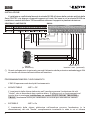
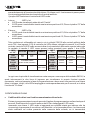
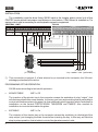
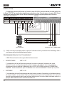
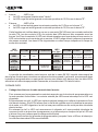
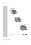
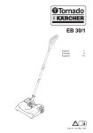
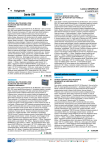
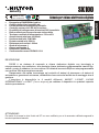
SK100
Lead free
Pb
EMC 2006/95/CE
compliant
RoHS
Scheda per chiave elettronica digitale
Generazione RANDOM del codice.
Codifica delle chiavi semplificata.
Funzionamento monostabile o bistabile.
Controllo esterno dei LED dell'inseritore.
Possibilità di collegare max 4 inseritori SKI in parallelo.
Relé ausiliario per riconoscimento chiave falsa.
Tensione nominale di alimentazione: 13Vcc ±5%
Assorbimento min/max: 40/80mA
Uscita contatti relè: C/NC/NA
Portata contatti relè: 24V 1A
Distanza max inseritori: 200mt
Grado di sicurezza: 1
Classe ambientale: 2
Dimensioni: 90x52mm
Conforme alla norma CEI EN 50131-1
ITALIANO
!
!
!
!
!
!
!
!
!
!
!
!
!
!
!
Made in Italy
RAEE
security
DESCRIZIONE
SK100 è un sistema di comando a chiave elettronica digitale con tecnologia a
microprocessore che sostituisce, alla obsoleta chiave elettronica programmabile tramite Dipswitch o punto di saldatura, la nuova chiave SK dotata di memoria EEprom autoprogrammabile
con codice a 32bit a generazione casuale.
Rappresenta una valida innovazione nel controllo di sistemi di sicurezza o di sistemi di
automazione, garantendo sicurezza, affidabilità ed una notevole facilità sia di montaggio che di
gestione.
L'inseritore è disponibile in 4 modelli differenti: MAGIC*, LIVING*, LIVING
INTERNATIONAL* e LIGHT* (*Marchi Registrati) per adattare il dispositivo in qualsiasi impianto
elettrico preesistente.
ATTENZIONE!
Per motivi di sicurezza le chiavi fornite nel KIT non sono codificate, per cui è necessario codificarle seguendo le
istruzioni riportate nel manuale.
1
SK100
security
INSTALLAZIONE
L’installazione va effettuata fissando la scheda SK100 all’interno della centrale antifurto della
Serie PROTEC che dispone di appositi agganci sul fondo. Nel caso in cui la scheda SK100 sia
installata su centrali della Serie TM è necessario utilizzare il supporto in plastica in dotazione.
SK100
CENTRALE ANTIFURTO
+
Alarm
NA C NC Sir
-
+ + +
S.A. 12Vcc int12V
Chiave
V R
led key
Com
zone
24H Z1 Z2 Z3 Z4 Z5 Z6 Z7 Z8
In serie alla
linea 24h (*)
Togliere il
ponticello
A
B
C
D
4S
SKI/NL
(in dotazione)
Verso altri 3
inseritori max (opzionali)
(*) Questo collegamento è opzionale; prevede l'attivazione della protezione antisabotaggio 24h
se inserita una chiave elettronica falsa nell'inseritore.
PROGRAMMAZIONE DEL FUNZIONAMENTO
L'SK100 opera secondo due tipi di funzionamento:
!
MONOSTABILE
JMP1 = Off
L' inserimento della chiave elettronica nell' inseritore provoca l'eccitazione del relè
"Uscita", che si disecciterà dopo qualche attimo. Si ottiene così un funzionamento ad
impulsi che si presta per installazione su centrali PROTEC6GSM, TM600GSM e
TM600P. Necessaria anche per installazione su centrali per automazione cancelli.
!
BISTABILE
JMP1 = On
L' inserimento della chiave elettronica nell'inseritore provoca l'eccitazione (o la
diseccitazione) del relè "Uscita", semplicemente invertendo lo stato in cui si trovava
2
SK100
security
precedentemente all'inserimento della chiave. Si ottiene così il funzionamento passo-passo,
che si presta preferibilmente al controllo di centrali antifurto.
Il jumper JMP2 seleziona il controllo del LED verde:
!
Interno:
JMP2 = Int.
6 Il LED verde visualizza lo stato del relè "Uscita".
6 Il LED rosso è controllabile tramite una tensione positiva di 13,5Vcc sul piedino "R" della
morsettiera.
!
Esterno:
JMP2 = Est.
6 Il LED verde è controllabile tramite una tensione positiva di 13,5Vcc sul piedino "V" della
morsettiera.
6 il LED rosso è controllabile tramite una tensione positiva di 13,5Vcc sul piedino "R" della
morsettiera.
Tale condizione è utilizzabile nel caso in cui si colleghi l'SK100 alle centrali antifurto della
serie TM; i due ingressi (V-R) di controllo dei LEDs vanno collegati ai morsetti V ed R sulla
centrale, cosicchè il LED verde acceso indica che la centrale è disinserita, spento indica che
la centrale è inserita; il LED rosso acceso indica eventuali zone aperte. I due LEDs
lampeggianti
contemporaneamente indicano il tempo
di uscita della centrale.
JMP2
JMP2
su "Int."
LED
VERDE
LED
ROSSO
ACCESO
SPENTO
Relè
ON
Relè
OFF
LAMPEG.
LED
VERDE
LED
ROSSO
Controllabile tramite
piedino 8 sulla morsettiera
LED
VERDE E
ROSSO
su "Est."
Inserimento
chiave falsa
ACCESO
SPENTO
LAMPEG.
Centrale
Centrale
Centrale
disinserita
inserita
disinserita
Zone incluse Zone incluse Zone escluse
Zona/e
aperta/e
LED
VERDE E
ROSSO
Zone
chiuse
Tempo
di uscita
In ogni caso la priorità di visualizzazione resta sempre e comunque della scheda SK100, la
quale interromperà le due linee di ingresso per visualizzare le proprie funzioni quando
necessario, come ad esempio in fase di programmazione o dopo avere riconosciuto una chiave
falsa; in tal caso, infatti, i due LEDs lampeggiano contemporaneamente per 5 secondi, e si attiva
l'uscita relè "Ch.falsa".
CODIFICA DELLE CHIAVI
!
Codifica delle chiavi con il codice memorizzato sulla scheda:
Entrare in programmazione tenendo premuto il tastino di programmazione sulla scheda per 4
secondi. Sarà interrotto il controllo esterno dei LEDs e lampeggerà il LED verde.
Inserendo una chiave, il LED verde si spegnerà per qualche istante per indicare che ha
riconosciuto la presenza di una chiave nell'inseritore: se si riaccenderà fisso, la chiave sarà
stata codificata col codice presente nella memoria della scheda; se si riaccenderà
3
SK100
security
lampeggiante, la chiave non sarà stata codificata essendo guasta o inserita male
nell'inseritore.
Togliendo la chiave, il LED verde tornerà a lampeggiare e sarà possibile inserire altre chiavi
da programmare, accertandosi per ogni chiave che il LED verde si accenda fisso, segno
dell'avvenuta codifica.
Premendo tre volte il tastino di programmazione (o dopo 3 min. e 30 sec. di attesa) si tornerà
in fase operativa; sarà riattivato il controllo esterno dei LEDs.
!
Codifica delle chiavi con un nuovo codice generato sulla scheda:
Entrare in programmazione tenendo premuto il tastino di programmazione sulla scheda per 4
secondi. Sarà interrotto il controllo esterno dei LEDs e lampeggerà il LED verde; tenendo
nuovamente premuto lo stesso tastino per altri 4 sec. lampeggerà il LED rosso. E' stato così
generato un nuovo codice.
Inserendo una chiave, il LED rosso si spegnerà per qualche istante per indicare che ha
riconosciuto la presenza di una chiave nell'inseritore; se si riaccenderà fisso, la chiave sarà
stata codificata con il nuovo codice presente nella memoria della scheda; se si riaccenderà
lampeggiante, la chiave non sarà stata codificata essendo guasta o inserita male
nell'inseritore.
Togliendo la chiave il LED rosso tornerà a lampeggiare e sarà possibile inserire le altre chiavi
da programmare, accertandosi per ogni chiave che il LED rosso si accenda fisso, segno
dell'avvenuta codifica.
Premendo tre volte il tastino di programmazione (o dopo 3 min. e 30 sec. di attesa) si tornerà
in fase operativa; sarà riattivato il controllo esterno dei LEDs.
!
Codifica delle chiavi con un nuovo codice acquisito da una chiave già codificata:
Disinserire, eventualmente, l'antifurto tramite la chiave meccanica della centrale.
Inserire la chiave codificata da cui si vuole acquisire il codice: la scheda non riconoscerà il
codice della chiave e si ecciterà il relè "Ch.falsa", causando il lampeggio contemporaneo dei
due LEDs. Sarà interrotto il controllo esterno dei LEDs. Attendere la fine del lampeggio dei
due LEDs.
Lasciando la chiave sempre inserita, tenere premuto il tastino di programmazione per 4
secondi: l'accensione fissa del LED rosso segnalerà che il codice è stato acquisito e
memorizzato nella scheda. Estraendo la chiave il LED rosso lampeggerà, e a questo punto è
possibile inserire una chiave nuova da codificare con il nuovo codice appena acquisito.
Il LED rosso si spegnerà per qualche istante per indicare che ha riconosciuto la presenza di
una chiave nell'inseritore; se si riaccenderà fisso, la chiave sarà stata codificata con il nuovo
codice presente nella memoria della scheda; se si riaccenderà lampeggiante, la chiave non
sarà stata codificata essendo guasta o inserita male nell'inseritore.
Togliendo la chiave il LED rosso tornerà a lampeggiare e sarà possibile inserire altre chiavi da
programmare, accertandosi per ogni chiave che il LED rosso si accenda fisso, segno
dell'avvenuta codifica.
Premendo tre volte il tastino di programmazione (o dopo 3 min. e 30 sec. di attesa) si tornerà
in fase operativa; sarà riattivato il controllo esterno dei LEDs.
4
SK100
Lead free
Pb
EMC 2006/95/CE
compliant
RoHS
SK electronic key 12V control board
RANDOM code.
Simplified keys programming.
Function monostable or bistable.
Connector LEDs external control.
Max 4 SKI in parallel.
Recognition of false key with relay contact.
Power supply voltage: 13Vdc ±5%
Absorption min/max: 40/80mA
Output relay: C/NC/NO
Relay contact: 24V 1A
Maximum operating gap:200mt
Safety degree: 1
Ambiental class: 2
Dimensions: 90x52mm
Approved directives CEI EN 50131-1
ENGLISH
!
!
!
!
!
!
!
!
!
!
!
!
!
!
!
Made in Italy
RAEE
security
DESCRIPTION
SK100 is a control-system with digital electronic key with microprocessor that replaces, to the
old electronic key programmable through Dip-switch or spot welding, the new key SK equipped
with EEprom auto-programmable memory with code 32bit random.
It represents a valid innovation in the safety systems or automation systems, warranting
safety, reliability and facility both of assemblage and of management.
The connector is available in four different models: MAGIC*, LIVING*, LIVING
INTERNATIONAL* e LIGHT* (*Registered Trademark) to adapt the system in any pre-existent
electric system.
WARNING!
For safety measures keys equipped in the KIT are not codified, so it is necessary to code them following the
instruction manual.
5
SK100
security
INSTALLATION
The installation must be done fixing SK100 card in the burglar alarm control unit of the
PROTEC series which has proper connections on the bottom. If Sk100card is installed on Tm
series control units is necessary to use the plastic support in equipment.
SK100
CENTRAL UNIT
+
Alarm
NA C NC Sir
-
+ + +
S.A. 12Vcc int12V
Chiave
V R
led key
Com
zone
24H Z1 Z2 Z3 Z4 Z5 Z6 Z7 Z8
In series
to 24h (*)
Remove
the bridge
A
B
C
D
4S
SKI/NL
(in dotation)
In other 3
key reader max (optionals)
(*) This connection is optional; if a false electric key is inserted in the connector, the 24h antisabotage protection will be active.
PROGRAMING OF THE OPERATION
SK100 works according to two kind of operation::
!
MONOSTABLE
JMP1 = Off
The insertion of the electric key in the connector causes the excitation of relay “output”, that
will discharge itself after some instants. In this way you have a pip working that is preferable to
control automation systems for gates.It is thus obtained a pulse operation which lends itself to
installation on the central PROTEC6GSM, TM600GSM and TM600P. Also needed for
installation on a central automation for gates.
!
BISTABLE
JMP1 = On
The insertion of the electric key in the connector causes the excitation (or discharge)of the
relay output, just changing the state it was before inserting the key. In this way, we have the
step-by-step operation, that is better to control burglar alarm control units.
6
SK100
security
The JMP2 jumper selects the control of green LED:
!
Inside:
JMP2 = Int.
6 The green LED visualizes the state of “output”relay.
6 The red LED is controllable trought a positive tension of 13,5V cc on the “R”pin of the
terminal box.
!
External:
JMP2 = Est.
6 The green LED is controllable trought a positive tension of 13,5V cc on the “V”pin of the
terminal box.
6 The red LED is controllable trought a positive tension of 13,5V cc on the “R”pin of the
terminal box.
This condition is available if SK100 is linked to the TM series anti-burglar control unit; two
control input (V-R) of the LEDs must be linked to the terminal V and R on the control-unit, so
green LED on,indicates that the control unit is disconnected, off means that the control unit is
connected; the on red LED indicates possible open zones. Two LEDs that flash
simoultaneously indicate the output time of the control unit.
JMP2
on "Int."
LED ON
LED OFF
GREEN
LED
Relay
ON
Relay
OFF
RED
LED
LAMP.
GREEN
LED
RED
LED
Controlable with
8 position on the clip
GREEN
AND RED
LED
JMP2
on "Est."
Insertion
false key
GREEN
AND RED
LED
ON
OFF
LAMP
Central unit Central unit Centrale unit
switched off switched on swithched off
Closed zones Open zones Esclused zones
Open
zone/s
Closed
zone/s
Output
time
In each case SK100 card has the priority on visualization, that will stop two input lines to
visualize its own functions when necessary, for example in programming phase or after having
recognize a false key; in this case, two LEDs flash simoultaneously for 5 seconds, and the output
relay “False Key”is active.
CODING OF KEYS
Coding of keys with the code saved on the card:
Enter in programming by pressing programming key on the card for 4 seconds. Exsternal
control of LEDs will be stopped and green LED will flash.
Inserting a key, green LED will stop for some instants to indicate that have reconignized the
presence of a key in the connector ; if it will glow fixed, the key will be coded with the new code
present in the memory of the card; if it will fash, the key will not have been coded because
broken or badly inserted in the connector.Removing the key the red LED will flash again and it
will be possibile to insert other keys to programm, verifying that red LED is turned on fixed for
each key,sign of the happended coding.
7
SK100
security
By pressing three times programming key (or after 3 min and 30 sec.)it will return to the
operational phase; the external control of LEDs will be active again.
!
Coding of the keys with a new code acquired by an already encoded key:
Disconnect,eventually, the burglar alarm through the mechanical key of the control unit.
Insert the coded key from which you want to acquire the code: the card won't recognize the
code of the key and the relay “False Key” will be excited, causing the simoultaneous flash of
the two LEDs.
Leaving the key always inserted, press again the programming key for 4 seconds: the fixed
lighting of the red LED will signal that the code has been acquired and memorized in the card.
Extracting the key the red LED will flash, and now it is possible to insert a new key to code with
the new code just acquired.
The red LED will switch off for some seconds to indicate that it has recognized the presence of
a key in the connector; if it will light fixed, the key will have been encoded with the new code
present in the memory of the card; it it will relight flashing, the key won't have been encoded
being broken or badly inserted in the connector.
Removing the key the red LED will flash again and it will be possible to insert other keys to
program, verifying for each key that the red LED is turned on fixed, sign of the happened
coding.
Pressing three times the programming key (or after 3 min.and 30 sec.) we will return in
operational phase; the external control of the LEDs will be active again.
!
Coding of the keys with a new code acquired by an already encoded key:
Disconnect,eventually, the burglar alarm through the mechanical key of the control unit.
Insert the coded key from which you want to acquire the code: the card won’t recognize the
code of the key and the relay “False Key” will be excited, causing the simoultaneous flash of
the two LEDs.
Leaving the key always inserted, press again the programming key for 4 seconds: the fixed
lighting of the red LED will signal that the code has been acquired and memorized in the card.
Extracting the key the red LED will flash, and now it is possible to insert a new key to code with
the new code just acquired.
The red LED will switch off for some seconds to indicate that it has recognized the presence of
a key in the connector; if it will light fixed, the key will have been encoded with the new code
present in the memory of the card; it it will relight flashing, the key won’t have been encoded
being broken or badly inserted in the connector.
Removing the key the red LED will flash again and it will be possible to insert other keys to
program, verifying for each key that the red LED is turned on fixed, sign of the happened
coding.
Pressing three times the programming key (or after 3 min.and 30 sec.) we will return in
operational phase; the external control of the LEDs will be active again.
8
SK100
Lead free
!
!
!
!
!
!
!
!
!
!
!
!
!
!
!
!
Made in Italy
Pb
EMC 2006/95/CE
compliant
RoHS
RAEE
security
Carte de contrôle 12V pour clè èlectronique SK
Code clef à 32 bit (4294967296 combinaisons).
Génération RANDOM du code.
Codage semplifié des clés .
Fonctionnement monostable ou bistable.
Contrôle externe des LEDs du lecteur.
Possibilitè max de connexion de lecteurs SKI max 4 .
Relais pour reconnaître les clés fausses.
Tension nominale d'alimentation: 13Vcc ±5%
Consommation min.& max.: 40/80mA
Sortie relais: C/NC/NA
Poussée contacts relais: 24V 1A
Distance max de fonctionnement: 200mt
Degré de sécurité: 1
Class environmental: 2
Dimensions: 90x52mm
Conforme normes CEI EN 50131-1
SK100 est un systeme de commande par clef electronique digitale avec technologie a
microprocesseur qui remplace les cles electroniques programmables par Dip-switch ou grace à
point de soudure; la nouvelle clef SK dotée de memoire EEprom auto-programmable avec code à
32bit à generation casual.
Il s’agit d’une innovation tres important dans le domaine du controle des systemes de
sécurité ou des systemes d’automatisme: il assure une efficacité et une simplicité soit dans le
montage soit pour ce qui concerne la gestion.
Le lecteurs est disponible en 4 types differents: MAGIC*, LIVING*, LIVING
INTERNATIONAL* et LIGHT* (*Marques enregistrées) pour adapter le dispositif à n’importe quelle
installation electrique préexistante.
ATTENTION!
Pour raisons de sécurité les clefs que vous trouverez dans le KIT ne sont pas codifiés, elles devront être
codifiées en faisant référence au manuel d'installation.
9
FRANÇAIS
DESCRIPTION
SK100
security
INSTALLATION
L’installation doit etre effectuée en fixant la carte SK100 à l’interieur de la centrale antivol de
la Serie PROTEC qui est dotée de attelages spécials au bas. Dans le cas ou la carte SK100 soit
installée sur centrales de la Serie TM est necessaire utiliser le support plastique en dotation.
SK100
CENTRALE ANTIVOL
+
Alarm
NA C NC Sir
-
+ + +
S.A. 12Vcc int12V
Chiave
V R
led key
Com
zone
24H Z1 Z2 Z3 Z4 Z5 Z6 Z7 Z8
En serie à la
ligne 24h (*)
Enlever la
barrette
A
B
C
D
4S
SKI/NL
(en dotation)
Vers autres 3
lecteurs max (optionnels)
(*) Cette connexion est optionnelle et prevoit l'activation de la protection anti-sabotage 24h si
une fausse clef est introduite dans le lecteur.
PROGRAMMATION DU FONCTIONNEMENT
L'SK100 marche selon deux types de fonctionnement:
!
MONOSTABLE
JMP1 = Off
L' introduction de la clef electronique dans le lecteur entraine l'excitation du relais
"Uscita", lequel se désexcite aprés quelque instant. On obtient ainsi une opération
d'impulsions qui se prête à l'installation sur le PROTEC6GSM central, et TM600GSM
TM600P. Aussi nécessaire pour l'installation sur une automatisation central pour portes .
!
BISTABLE
JMP1 = On
L' introduction de la clef electronique dans le lecteur entraine l'excitation (ou la désexcitation)
du relais "Uscita", en invertant l’état ou il était précédemment à l'introduction de la clef. Ce
type de fonctionnement pas à pas est bien indiqué pour le controle des centrales antivol.Le
jumper JMP2 sélectionne le controle du LED vert:
10
SK100
security
!
Interne:
JMP2 = Int.
6 Le LED vert signale l’ètat du relais "Uscita".
6 Le LED rouge est activé grace à une tension positive de 13,5Vcc sur le borne "R".
!
Externe:
JMP2 = Est.
6 Le LED vert est activé grace à une tension positive de 13,5Vcc sur le borne “V”.
6 Le LED rouge est activé grace à une tension positive de 13,5Vcc sur le borne "R".
Cette fonction est à utiliser dans le cas ou on connecte l'SK100 avec les centrales antivol de
la série TM; les deux entrée (V-R) de controle des LEDs doivent être connexès avec les
bornes V et R sur la centrale: le LED vert allumé signalera que la centrale est hors service, le
LED verte eteinte que la centrale est en service; le LED rouge allumé indiquera la presence
des zones ouvertes. Les deux LEDs clignotantes en même temps indiqueront le temps de
sortie de la centrale.
JMP2
sur "Int."
ALLUMÉ
LED
VERT
Relais
ON
LED
ROUGE
ÉTEINT CLIGNOTANT
LED
VERT
Relais
OFF
LED
ROUGE
À contrôler par le borne 8
LED
VERT ET
ROUGE
JMP2
sur "Est."
Introduction
fausse clef
LED
VERT ET
ROUGE
ALLUMÉ
ÉTEINT
CLIGNOT.
Centrale
Centrale
Centrale
hors service en service
disinserita
Zones incluse Zones incluse Zones exclue
Zone/s
ouverte/s
Zones
fermées
Temps
de sortie
La priorité de visualisation reste toujours cela de la carte SK100, laquelle interromprà les
deux lignes d’entrée pour visualiser ses propres fonctions quand il y a besoin, par exsemple dans
la phase de programmation ou après avoir reconnu une fausse clef; dans ce cas, les deux LEDs
etincellent en même temps pendant 5 secondes, et la sortie relais "Ch.falsa"s’active .
CODAGE CLÈS
!
Codage des clès avec le code memorisé sur la carte:
Pour commencer la programmation maintenir appuyée sur la touche de programmation sur
la carte pendant 4 secondes. Le controle externe par LEDs sera interrompu et le LED vert
clignotera.
En introduisant une clef, le LED vert s’eteint quelque instant pour indiquer la presence d’une
clef dans le lecteur: Si le LED s’allume fixe, la clef a etè codifiée avec le code dans la memoire
de la carte; si le LED clignotera, la clef ne sera pas codifiée car elle a etè pas bien introduite
dans le lecteur.
En enlevant la clef, le LED vert recommence à clignoter et il sera possible introduire de
nouveau la clef ou autres cles à programmer, en s’assurant pour chaque clef qui le LED vert
s’allume fixe, pour indiquer que le codage a eté effectué.
En appuyant trois fois sur la touche de programmation (ou après 3 min. et 30 sec. d’attente) in
le controle externe des LEDs sera réhabilité.
11
SK100
!
security
Codage des clés avec un nouveau code programmé sur la carte:
Pour commencer la programmation maintenir appuyè sur la touche de programmation sur la
carte pendant 4 secondes. Le controle externe des LEDs sera interrompu et le LED vert
clignotera; en appuyant de nouveau sur la même touche pendant 4 sec. le LED rouge
clignotera à indiquer que un nouveau code a eté programmé.
Quand on introduit une clef, le LED rouge s’eteint quelque instant à indiquer la presence
d’une clef dans le lecteur; Si le LED s’allume fixe, la clef a etè codifiée avec le nouveau code
dans la memoire de la carte; si le LED clignotera, la clef ne sera pas codifiée car elle a etè pas
bien introduite dans le lecteur.
En enlevant la clef, le LED rouge recommence à clignoter et il sera possible introduire de
nouveau la clef ou autres cles à programmer, en s’assurant pour chaque clef qui le LED
rouge s’allume fixe, pour indiquer que le codage a eté effectué.
En appuyant trois fois sur la touche de programmation (ou après 3 min. et 30 sec. d’attente) le
controle externe des LEDs sera réhabilité.
!
Codage des clés avec un nouveau code acquis de une clef dejà codifiée:
Mettre hors service le dospositif antivol par la clé mécanique de la centrale.
Introduire la clé codifiée dont on veut acquisir le cod: la carte ne reconnaitra le code de la clef
et le relais "Ch.falsa" s’excitera, donc les deux LEDs clignoteront dans le mêm temps. Le
controle externe des LEDs sera interrompu.
Quand les deux LEDs s’arretent, avec la clef toujours introduite, maintenir appuyée la touche
de programmation pendant 4 secondes: le LED rouge s’allume fixe pour indiquer que le code
a eté acquis et memorisé dans la carte. En enlevant la clef, le LED rouge clignotera pour
indiquer que il est possible d’indroduire une nouvelle clef à codifier par ll nouveau code juste
acquis.
Le LED rouge s’etent qualque instant pour indiquer que la presence d’une nouvelle clef dans
le lecteur a eté reconnu; si il s’allume fixe de nouveau, la clef aura été codifiée par un nouveau
code dans la memoire de la carte; si le LED clignotera, la clef ne aura pas été codifiée car elle
a etè pas bien introduite dans le lecteur.
En enlevant la clef, le LED rouge recommence à clignoter et il sera possible introduire de
nouveau la clef ou autres cles à programmer, en s’assurant pour chaque clef qui le LED
rouge s’allume fixe, pour indiquer que le codage a eté effectué.
En appuyant trois fois sur la touche de programmation (ou après 3 min. et 30 sec. d’attente) le
controle externe des LEDs sera réhabilité.
12
108ADIEF-4.01