1
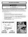
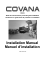
OASIS Read this manual before proceeding with installation Veuillez lire ce guide avant de procéder à l’installation Installation Manual Manuel d’installation www.covana.com FRANÇAIS La version française du manuel débute à la page 23. 2 WARNING RISK OF ELECTROCUTION ALL ELECTRICAL WIRING MUST BE DONE BY A QUALIFIED PROFESSIONAL. THE WIRING MUST MEET THE REQUIREMENTS OF ALL APPLICABLE LOCAL CODES AND REGULATIONS. WARNING RISK OF ELECTROCUTION THE COVANA OPERATOR MUST BE CONNECTED TO A DEDICATED GFCI (GROUND FAULT CIRCUIT INTERRUPTERS) PROTECTED CIRCUIT. REFERENCE: MUST COMPLY WITH ALL APPLICABLE LOCAL CODES AND REGULATIONS. WARNING RISK OF INJURY DISCONNECT OR TURN OFF ALL POWER SUPPLY BEFORE STARTING ANY INTERVENTION ON THE COVANA. WARNING RISK OF INJURY DO NOT OPERATE THE COVANA WHILE IN WATER. WARNING AVOID DROWNING RISK ENTRAPMENT POSSIBLE FAILURE TO FOLLOW ALL INSTRUCTIONS MAY RESULT IN INJURY OR DROWNING. INSPECT COVER PERIODICALLY. POWER SAFETY COVER MEETS ASTM F1346-91 REQUIREMENTS. 3 IMPORTANT OBSERVE THE FOLLOWING STEPS FOR PROPER ASSEMBLY AND SETUP OF THE COVANA. IMPORTANT DO NOT OPERATE THE UNIT UNTIL ALL MECHANICAL AND ELECTRICAL CONNECTIONS HAVE BEEN MADE. IMPORTANT ALL 4 POSTS OF THE COVANA MUST BE PROPERLY ANCHORED TO ITS FOUNDATION USING THE ANCHORING HOLES LOCATED AT THE FOOT OF EACH POSTS. THE OPTIONAL NON PERMANENT MOUNTING PLATES CAN BE USED WHEN ANCHORING IS NOT POSSIBLE. IMPORTANT LIMIT SWITCHES ADJUSTMENT BOTH THE UP & DOWN LIMIT SWITCHES ARE PRE-ADJUSTED AT THE FACTORY. THE DOWN LIMIT SWITCH SHOULD NEVER BE READJUSTED. THE UP LIMIT SWITCH SHOULD ONLY BE ADJUSTED TO REDUCE THE MAXIMUM HEIGHT OF THE ROOF TO AVOID POSSIBLE CONTACT WITH ITS SURROUNDINGS. REFER TO THE LIMIT SWITCH ADJUSTMENT GUIDE FOUND IN THIS MANUAL BEFORE MAKING ANY ADJUSTEMTS. IMPROPER ADJUSTMENT CAN RESULT IN DAMAGE TO THE DRIVE SYSTEM. IMPORTANT DO NOT STEP ON THE COVANA OPERATOR. 4 NOTICE THIS OPERATOR IS SPECIALLY DESIGNED TO OPERATE ONLY WITH THE COVANA LIFTING SYSTEM. UNDER NO CIRCUMSTANCES SHOULD THIS OPERATOR BE USED FOR ANY OTHER APPLICATIONS. NOTICE DISPOSAL: THIS PRODUCT MAINLY CONTAINS STEEL, COPPER (CU) AND ALUMINUM DIE-CAST (AL). THE GEARBOX CONTAINS OIL AND OTHER MATERIALS. PLEASE RECYCLE WISELY NOTICE REMOVE THE CONTROL KEY AFTER OPERATING THE COVANA. STORE THE KEY IN A SECURE LOCATION WHEN NOT IN USE. BRING THE KEY WITH YOU IN THE SPA TO PREVENT UNAUTHORIZED OPERATION OF THE COVANA. NOTICE The key switch must be permanently mounted and located 5 feet (1.5 m) away from the spa and 5 feet (1.5 m) above the deck. User must have full view of the Covana when operating. Roof 5 feet 1.5 meters 5 feet 1.5 meters Spa 5 PREPARING A PROPER FOUNDATION Just like the spa, the Covana requires a solid foundation. The area that the Covana sits on must be able to support at least 600 lb (272 kg) and must be leveled. All components of the Covana must be supported by the foundation. Note: Damage caused by inadequate or improper foundation support is not covered by the Covana warranty. It is the responsibility of the owner to provide proper foundation. Foundation recommendation: 1. 2. Engineered wood deck OR concrete pad - 4" (10 cm) thick. Each of the 4 posts on the Covana must be properly anchored to the foundation using at least one of the pre-drilled holes located at the foot of each post. Use a 1/4” (0.6 cm) concrete anchor for concrete pads or a 1/4” (0.6 cm) lag bolt for wood foundations of a minimum of 1-1/4” (3 cm) long. COVANA ELECTRICAL REQUIREMENTS 1. 2. 3. 4. The Covana requires a dedicated 115V (North America) or 230V (Europe) permanently connected (hard wired) power supply. The Covana motor has a dedicated connection for 115V (North America) or 230V (Europe), please see enclosed connection diagram. The Covana must be installed in accordance to and comply with all applicable local codes and regulations. All wiring should be installed by a qualified electrician. Wire and conduit should be sized as per local codes and regulations. The electrical circuit for the Covana must include a suitable ground fault interrupter (GFCI) as required to comply with codes and regulations. Required Voltage: Required GFCI Breaker: Max Covana current draw: 115V (North America) 230V (Europe) (1 hot, 1 neutral, 1 ground) 15A (North America) 10A (Europe) single-pole GFCI breaker, not included 12 (North America) 6 (Europe) Amps KEY OPERATING INSTRUCTIONS Turn the key to the right — clockwise to raise the roof. Turn the key to the left — counterclockwise to lower the roof. The key will automatically return to center, off position, when released. 6 SIDE ELEVATION DIMENSIONS 21" (53 cm) The maximum elevation height depends on the height of the spa. Add spa height to the Covana travel to determine maximum elevation. Covana maximum travel is 50" (1.27 m) Example: Spa height + Covana travel which is 50” (1.27 m) = Total elevation Spa height will vary and must be within these measurements Minimum is 34" (86 cm) Maximum is 48" (1.22 m) 7 FRAME DIMENSIONS AND FOOTPRINT 8 FRAME DIMENSIONS AND FOOTPRINT 9 GROUNDING AND CONNECTION OF POWER SUPPLY WARNING RISK OF INJURY DISCONNECT OR TURN OFF ALL POWER SUPPLY BEFORE STARTING ANY INTERVENTION ON THE COVANA. Remove the four screws on the bottom side of the Covana operator and take the cover off. Pre-wired key switch with 20’ (7,5 m) of cable included. Cable must be run through a conduit. Connect the ground cable of the main power supply to the provided terminal. OPERATOR Connect the main 115V (North America) 230V (Europe) power to their respective terminals. Use the provided terminals to bond the Covana operator. Reinstall the operator cover. 10 LIMIT SWITCH ADJUSTMENT WARNING RISK OF INJURY DISCONNECT OR TURN OFF ALL POWER SUPPLY BEFORE STARTING ANY INTERVENTION ON THE COVANA. Note: The UP & DOWN limits are factory adjusted and there is no need for re-adjustment. If adjustments are required to ensure the Covana roof does not come into contact with its surroundings while elevating, the UP direction may be decreased. Never change the factory settings of the DOWN limits or increase the UP limit. Failing to do so may result in possible equipment damage and/or injury. Disconnect or turn power off. Remove the four screws at the bottom of the operator and take the cover off. Remove the retaining screw and slide the cam plate from operator frame. To reduce the travel in the UP direction, turn the UP cam counterclockwise as per arrow. Once the cam is set to the desired position, reinstall the cam plate and make sure that it is properly inserted in the slot of each cam. NEVER OPERATE THE SYSTEM WITH THE CAMPLATE REMOVED. Reinsert the retaining screw to prevent the cam plate from coming out. Reinstall the operator cover. Turn the power ON and test the system. Cam plate and retaining screw 11 MANUAL OPERATION IN CASE OF POWER FAILURE WARNING RISK OF INJURY DISCONNECT OR TURN OFF ALL POWER SUPPLY BEFORE STARTING ANY INTERVENTION ON THE COVANA. 1. 2. 3. Disconnect or turn power off. Remove the four screws at the bottom of the operator and take the cover off. Use 1/2" or 1.3 cm hexagon socket wrench to operate the operator by turning the input shaft. SLOWLY TURN THE SHAFT - STOP IF EXCESS TENSION IS FELT. NEVER USE A POWER TOOL AS THIS WILL DAMAGE UNIT. 4. 5. 6. Turn the input shaft clockwise to lower the roof and counterclockwise to raise the roof. Reinstall the operator cover. Reconnect or turn power on. COVER OPERATOR 12 WIRING & SCHEMATIC DIAGRAM - 120VAC, 60HZ OPERATOR (NORTH AMERICA) 13 WIRING & SCHEMATIC DIAGRAM - 220VAC, 50HZ OPERATOR (EUROPE) 14 INSTALLATION REQUIRED TOOLS Scissors / Retractable blade knife Robertson screwdriver Hammer 5. Remove the four (4) sleeve boxes from the crate and place them in a safe place – two (2) boxes per side. Be careful not to damage the cover. 6. Remove the parts box, the foams and the seals package from the crate and place them in a safe place. Use a hammer to remove the front wood board by hitting it. 7. Use the Robertson screwdriver to remove the two (2) screws holding the motor box. Imperial wrench (3/8") 7/32” Allen wrench UNCRATING 1. 2. 3. 4. Before uncrating the unit, make sure there is no apparent damage to the crate. In case of suspicious damage, take photos. If any damage is discovered, call Covana customer service at 1-877-278-8010. Stand the Covana in the vertical position. Ensure wind conditions allow for this to be done safely. With the retractable blade knife or scissors, cut and remove the front cardboard. Use scissors to cut and remove the four (4) cable ties holding the sleeve boxes – two (2) boxes per side. 15 8. Use the 3/8'' Imperial wrench to unscrew the screws holding the bottom of the jack – one (1) screw per side. 9. Use the 7/32'' Allen key to unscrew the screws holding the bracket with the jack – one (1) screw per side. 10. With the help of one other person, remove the motor end post assembly from the crate. We recommend one hand under the main frame and one holding the vertical post. Handle and carry the assembly so that the posts are straight and parallel. DO NOT TWIST. 11. Use the Robertson screwdriver to unscrew the four (4) screws on the aspenite sheet at the bottom of the crate – one (1) sheet per side. 12. Remove the aspenite sheet at the bottom of the crate. Remove the extrusions and the jacks at the bottom of the crate. 13. 14. With the help of one other person, flip the crate horizontally on its back side. One (1) person on each side of the side panel. 16 15. With the retractable blade knife or scissors cut and remove the top cardboard. 20. With the help of one other person, lift up the cover by holding it in the middle of the edges and place it on the spa. ***WARNING*** When handling the cover, make sure to support the complete assembly with your hands (both inner shell and outer shell must be supported). DO NOT GRAB THE OUTER SHELL EDGE ALONE TO LIFT THE COVER, THIS WOULD DAMAGE THE OUTER SHELL CORNER. 16. If your Covana comes with roller shades, remove the cardboard cylinder from the holes in the side panels and place them in a safe place. Be careful not to damage the cover. Use a hammer to remove the last wood board in the front of the crate. Note: The cover alone is approximately 220 lb. You might want to split the cover in two parts if you need to move it where space is limited. To do so, gently pull off the outer shell. ASSEMBLING 17. 1. Attach the foam spacers, using tape, to the top of the spa near each corner. 2. Place and center the roof of the Covana on the spa, pay attention to the short side and long side. The light switch, if a LED light kit option is installed in the cover, should be placed on the entry side of the spa. If the Covana has the optional lights, perform the LED light kit installation/ procedure. Instructions are on the next page. Loosen the lower sleeve retaining bolt, no more than five turns. Note that the sleeve must be put back in place between the 2 washers. Use the 3/8'' Imperial wrench to unscrew the four (4) roof brackets from the side panels – four (4) screws per side. 3. 4. 18. 19. Use the Robertson screwdriver to unscrew the three (3) screws holding the side panels to the bottom of the crate. Note: It is possible, for ease of installation, to completely take off the sleeve assembly from the post. To do so, remove the cap screw located at the top of the sleeve with a 7/32” Allen wrench. Remove the side panels by hitting them outward with a hammer – one (1) panel per side. 17 5. 6. 7. Lay the sleeves in a safe location, preferably horizontal on a soft surface. Position the motor and two post assembly in place, usually to the rear of the spa. Slide the jacks against the cover’s corners. Slide the drive shafts over the square shaft located at the bottom of both motor side jacks. 12. Jack lock bracket located at the bottom of non-motor side jacks can now be safely removed. LIGHTING INSTALLATION (OPTIONAL FEATURE) 8. For the non-motor side jacks, hold the jack vertical and in line with the drive shaft (square tube). Using a 3/4” wrench on the square shaft at the bottom of the jack, make fine adjustments so it is in line with the drive shaft and carefully slide the square shaft of the jack into the drive shaft. 9. 10. 11. 1. Lift the outer shell on the side where the battery is located to access the connections of the Solar Panel. Do not lift more than 16” (40 cm). 2. Install the battery in its foam support (located left of the on/off switch inside the top.) Make sure to correctly connect the positive “+” and negative “-” wires to the proper battery terminal. Each wire is clearly labeled accordingly. Install the aluminum U frame over the drive shaft and post bracket. Fasten in place using hardware provided, 4 bolts + 4 nuts + 8 washers. Perform steps 8 to 9 on the second non-motor side jack. Assemble and install the front frame with the cut-out for the steps. IMPORTANT Determine the corner of the Covana that is likely to receive the most sun, generally south is best; ensure there are no interfering objects. Take note that the battery is shipped inside the hardware kit. The battery is installed on the same short side as the on/off switch. Take note the switch should be positioned at the entry side of the spa. Ensure that all the hardware securing the outer shell to the inner shell is removed. Lights should operate for about 4 hours on a full charge. 18 3. Outside installation – Remove the solar panel from the box located inside the top of the Covana. Connect the solar panel to the lighting wire harness and place the wires and panel to the corner of the Covana where the panel will be mounted. The blue light MUST be located at the top of the solar panel. Apply pressure and rock the panel back and forth to ensure proper adhesion. 4. Show Room installation — Determine the best corner to locate the charger connection; generally the back side would be less visible. Connect the charger on the outside of the cover. Hide the cord of the solar panel inside the unit so it appears to be installed. 7. 8. If using the solar panel, check to ensure the panel is working – blue flashing light. Continue with final installation. Note: The charger is only to be used in a show room and is not designed or intended to be used outdoors. 5. 6. Lower the outer shell back over the inner shell taking care to ensure the wires are not pinched and are placed in the slit of the outer shell corner. Insert the suction cups in the panel; then remove the protective layer from the foam tape on the back suction cups. Carefully place the panel 3” (7.5 cm) up from the corner and center the panel on the ridge of the roof. 19 7. Verify that all four corner brackets are positioned at the same height. 8. Then, using the self drilling screws, insert four screws per post. FINAL ASSEMBLY AT THIS POINT, THE ELECTRICAL POWER SUPPLY MUST BE CONNECTED TO CONTINUE THE INSTALLATION. THIS WILL ENSURE THE PROPER SETTINGS CAN BE MADE. 1. Mount key box as per instructions on page 4. 2. 3. 4. Test system by turning key clockwise to elevate posts. Continue holding key until motor stops automatically and posts are fully elevated. Turn the key counterclockwise to lower the jacks, continue holding key until motor stops automatically and posts are fully lowered. Measure from the foot to the top of the jack. Maximum height should be 51.5” (1.28 m). Reinstall the post sleeves. Ensure the all-weather kit is fully slid down to make contact with the outer sleeve. Ensure that one washer is on the inside and the other washer is on the outside at the bottom of the posts. IMPORTANT: Make sure there is no gap between the sleeve and the bracket. Finish by tightening the four M6 screws on the cover. IMPORTANT: There should not be any gap between the cover and the sleeve. 5. 6. Make sure the cover is centered and leveled on the hot tub. Install corner brackets at each corner. Fasten the bracket to the cover with the M6 first. Do not tighten completely. 20 9. Make sure the Covana is centered and aligned with respect to the spa on all four sides. If necessary, reposition the post’s foot and frame accordingly. 10. Verify that all the posts are leveled on both sides. Reposition the posts if necessary. To insure a square installation, measure both 11. 12. Ensure that the middle sleeve is running freely up and down. If the middle sleeve stays up or does not move freely, verify installation on points 5 to 11. 13. Test the system to verify the cover elevates normally. Make sure there is no object directly above or in the path of the opening cover while performing this test; refer to limit switches adjustment instructions on page 11 if adjustments need to be made. Lower the cover and ensure it stops at the point of contact with the eight foam spacers on the spa. Readjust the corner brackets if contact is not made. Each of the 4 posts on the Covana must be properly anchored to the foundation using at least one of the pre-drilled holes located on the foot of each post. a. Use a 1/4” (0.6 cm) concrete anchor for concrete pads or a 1/4” (0.6 cm) lag bolt for wood foundations. Minimum of 1-1/4” (3 cm) long. b. The optional non permanent mounting plates can be used when anchoring is not possible. 14. 15. diagonals of the post and make sure they are identical. 21 6. Test by lowering the cover again to ensure that the seal makes contact on the entire perimeter. If satisfied, elevate the cover, remove the red plastic backing off the seal and lower the roof to the seal. 7. Let the cover rest in this position for two minutes to ensure proper seal-to-cover adhesion. APPLYING THE SEAL 1. 2. 3. 4. 5. Once the Covana has been fully assembled, elevate the cover using the key switch and remove the foam spacers. Lower the cover, walk around the entire perimeter of the spa observing where the white inside shell makes contact with the spa. This will determine the best location to apply the seal. Ensure the spa edge is completely dry. With the cover elevated, apply the provided seal clips to the spa in the predetermined area for the seal. The ideal location for the seal is closer to the inside/water edge. To obtain straight lines, use clips in the corners only. Install the seal starting at motor end with the adhesive layer pointing up towards the roof. Use the supplied seal connector in both ends of the seal. A clean cut must be performed so when closed, the hot spa is perfectly sealed. IMPORTANT – Now elevate the cover no more than an inch and let the cover rest again for a short period of time (a few seconds) as this will allow the seal to slowly and fully release from the seal clips. A plastic tool or your fingers can be used to help release the seal. 8. Once satisfied that the seal is released, elevate the cover and remove the seal clips from the tub edge. 9. Lower the cover and verify again for proper seal. If satisfied, elevate the cover and finalize the seal installation by applying pressure on the seal perimeter to properly set the adhesive on the inner surface. ASSISTANCE NOTE – At this stage, if the ambient air temperature is below 32⁰F (0⁰C), a temporary heater must be placed inside the spa for 10 to 15 minutes. When the heater is in the spa, bring down the cover until it touches the seal to increase the air temperature. After 10 to 15 minutes, remove the heater and continue with the seal installation. You can also refer to the videos available on Youtube. Go to www.covana.com and click on the YouTube button. For immediate assistance, please call us between 8 am to 12 pm and 1 pm to 5 pm EST at 1-877-278-8010. 22 Made in Canada by Canimex www.covana.com PATENTED Covana007-EN-FR / 202558 CANADA 2,532,429 US 11/162,557 UK 0515168.3 AUSTRALIA 2006200251 23 OASIS Veuillez lire ce guide avant de procéder à l’installation Manuel d’installation www.covana.com 24 25 AVERTISSEMENT RISQUE D’ÉLECTROCUTION TOUT LE CÂBLAGE DOIT ÊTRE EFFECTUÉ PAR UN PROFESSIONNEL QUALIFIÉ. LE CÂBLAGE DOIT RESPECTER TOUS LES CODES ET LES RÈGLEMENTS MUNICIPAUX APPLICABLES. AVERTISSEMENT RISQUE D’ÉLECTROCUTION LE MOTEUR DU COVANA DOIT ÊTRE RACCORDÉ À UN CIRCUIT PROTÉGÉ PAR UN DISJONCTEUR DE MISE À LA TERRE. RÉFÉRENCE : DOIT SE CONFORMER À TOUS LES CODES ET RÈGLEMENTS MUNICIPAUX. AVERTISSEMENT RISQUE DE BLESSURE DÉBRANCHEZ OU COUPEZ L’ALIMENTATION AVANT DE PROCÉDER À TOUTE INTERVENTION SUR LE COVANA. AVERTISSEMENT RISQUE DE BLESSURE NE PAS UTILISER LE COVANA LORSQUE VOUS ÊTES DANS L’EAU. AVERTISSEMENT ÉVITEZ LES RISQUES DE NOYADE RISQUE DE PRISE AU PIÈGE POSSIBLE LE NON-RESPECT DE TOUTES LES CONSIGNES PEUT ENTRAÎNER DES BLESSURES OU LA NOYADE. INSPECTEZ LE TOIT RÉGULIÈREMENT. CONFORME À LA NORME ASTM F1346-91 : POWER SAFETY COVER. 26 IMPORTANT VEUILLEZ SUIVRE LES ÉTAPES SUIVANTES AFIN D’ASSEMBLER ET DE CONFIGURER CORRECTEMENT LE COVANA. IMPORTANT NE PAS UTILISER LE COVANA AVANT QUE TOUTES LES CONNEXIONS MÉCANIQUES ET ÉLECTRIQUES SOIENT EFFECTUÉES. IMPORTANT TOUS LES POTEAUX DU COVANA DOIVENT ÊTRE CORRECTEMENT ANCRÉS À LA FONDATION AU MOYEN DES TROUS D’ANCRAGE SITUÉS AU PIED DE CHAQUE POTEAU. ON PEUT ÉGALEMENT SE SERVIR DES PLAQUES DE FIXATION NON PERMANENTES OPTIONNELLES LORSQUE L’ANCRAGE EST IMPOSSIBLE. IMPORTANT AJUSTEMENT DES INTERRUPTEURS DE FIN DE COURSE LES INTERRUPTEURS DE FIN DE COURSE SUPÉRIEURE ET INFÉREURE SONT PRÉAJUSTÉS EN USINE. NE JAMAIS RÉ-AJUSTER L’INTERRUPTEUR DE FIN DE COURSE INFÉRIEURE. AJUSTER L’INTERRUPTEUR DE FIN DE COURSE SUPÉRIEURE SEULEMENT POUR BAISSER LA HAUTEUR MAXIMUM DU TOIT AFIN DE PRÉVENIR TOUT CONTACT AVEC LES OBJETS ENVIRONNANTS. VEUILLEZ CONSULTER LE GUIDE D’AJUSTEMENT DES INTERRUPTEURS DE FIN DE COURSE DANS CE MANUEL AVANT DE PROCÉDER AUX AJUSTEMENTS. L’AJUSTEMENT INCORRECT PEUT CAUSER DES DOMMAGES AU SYSTÈME D’ENTRAÎNEMENT. IMPORTANT NE PAS MARCHER SUR LE MOTEUR DU COVANA. 27 AVIS LE MOTEUR EST SPÉCIFIQUEMENT CONÇU POUR FONCTIONNER AVEC LE SYSTÈME DE LEVAGE DU COVANA. Il NE DEVRAIT SOUS AUCUNE CIRCONSTANCE ÊTRE UTILISÉ À D’AUTRES FINS. AVIS MISE AU REBUT : CE PRODUIT CONTIENT PRINCIPALEMENT DE L’ACIER, DU CUIVRE (CU) ET DE L’ALUMINIUM SOLIDE (AL). LA BOÎTE D’ENGRENAGES CONTIENT DE L’HUILE ET D’AUTRES MATÉRIAUX. VEUILLEZ LE RECYCLER CONVENABLEMENT. AVIS RETIREZ LA CLÉ DE L’INTERRUPTEUR QUAND VOUS AVEZ FINI D’UTILISER LE COVANA. RANGEZ LA CLÉ DANS UN ENDROIT SÛR POUR QU’ELLE NE SOIT PAS UTILISÉE. AMENEZ LA CLÉ AVEC VOUS DANS LE SPA POUR EMPÊCHER UN FONCTIONNEMENT INADVERTANT DU COVANA. AVIS Toit L’interrupteur à clé doit être fixé de façon permanente à une distance de 5 pieds (1,5 m) du spa et à 5 pieds (1,5 m) au-dessus du sol avec une vue directe sur le Covana lors du fonctionnement. 5 pieds 1,5 mètre 5 pieds 1,5 mètre Spa 28 PRÉPARATION DE LA FONDATION Tout comme pour le spa, la fondation du Covana se doit d’être solide. L’emplacement où le Covana est placé doit pouvoir supporter au minimum 600 lb (272 kg) et être de niveau. Tous les composants du Covana doivent être supportés par la fondation. Remarque : Les dommages éventuels causés par une surface d’installation inadéquate ne sont pas couverts par la garantie de Covana. Le propriétaire est responsable de fournir une surface de support adéquate. Surface de support et fondation recommandée : 1. Sol en madriers OU plateforme de béton de 4 po (10 cm) d’épaisseur. 2. Les quatre montants du Covana doivent être correctement fixés à la surface fondation par le moyen des trous d’ancrage prépercés au pied de chaque poteau. Utilisez un ancrage pour béton de 1/4 po (0,6 cm) pour les plateformes cimentées ou un tire-fond de 1/4 po (0,6 cm) pour les fondations de bois d’une longueur minimum de 1 ¼ po (3 cm). EXIGENCES ÉLECTRIQUES DU COVANA 1. 2. 3. 4. Le Covana requiert une alimentation raccordée en permanence (câblée) de 115 V (Amérique du Nord) ou 230 V (Europe) Le moteur du Covana a une connexion dédiée pour 115 V (Amérique du Nord) ou 230 V (Europe). Veuillez consulter le schéma de connexion pages 34 et 35. Le Covana doit être installé conformément à tous les codes et règlements locaux applicables. Tout câblage doit être installé par un électricien qualifié. Le calibre du fil et du conduit doit être conforme aux codes et règlements locaux. Le circuit électrique du Covana doit inclure un disjoncteur de mise à la terre pour se conformer aux codes et réglementations. Tension requise : 115 V (Amérique du Nord) ou 230 V (Europe) (1 positif, 1 neutre, 1 mise à la terre) Disjoncteur de fuite à la terre requis : Disjoncteur de fuite à la terre à pôle unique 15 A (Amérique du Nord) ou 10 A (Europe), non inclus Courant d’alimentation max du Covana : 12 ampères (Amérique du Nord) ou 6 ampères (Europe) CONSIGNES D’UTILISATION DE LA CLÉ Tournez la clé vers la droite – dans le sens horaire pour lever le toit. Tournez la clé vers la gauche – dans le sens antihoraire pour abaisser le toit. Lorsque vous la relâchez, la clé reviendra automatiquement au centre, en position d’arrêt. 29 DIMENSIONS D’ÉLÉVATION DES CÔTÉS 21" (53 cm) La hauteur maximale d’élévation dépend de la hauteur du spa. Afin de déterminer l’élévation maximum, La hauteur maximale de ajoutez la hauteur du spa à la hauteur déplacement du Covana est 50 de déplacement du Covana. po (1,27 m) Exemple : Hauteur du spa + hauteur de déplacement du Covana de 50 po (1,27 m) = Élévation totale La hauteur du spa varie, mais doit être dans la plage suivante : Minimum de 34 po (86 cm) Maximum de 48 po (1,22 m) 30 DIMENSION DU CADRE ET DE LA SURFACE AU SOL 31 DIMENSION DU CADRE ET DE LA SURFACE AU SOL 32 MISE À LA TERRE ET RACCORDEMENT DE LA SOURCE D’ALIMENTATION AVERTISSEMENT RISQUE DE BLESSURE DÉBRANCHEZ OU COUPEZ L’ALIMENTATION AVANT DE PROCÉDER À TOUTE INTERVENTION SUR LE COVANA. Retirez les quatre vis sur les côtés du couvercle du moteur du Covana, et enlevez le. Interrupteur à clé précâblé avec 20 pieds (7,5 m) de câble inclus. Le câble doit passer dans un conduit. Raccordez le câble de mise à la terre de la source d’alimentation principale à la borne prévue à cet effet. MOTEUR Raccordez l’alimentation principale de 115 V (Amérique du Nord) ou 230 V (Europe) aux bornes respectives. Utilisez les bornes de mise à la terre pour raccorder le Covana. Réinstallez le couvercle du moteur. 33 AJUSTEMENT DE L’INTERRUPTEUR DE FIN DE COURSE AVERTISSEMENT RISQUE DE BLESSURE DÉBRANCHEZ OU COUPEZ L’ALIMENTATION AVANT DE PROCÉDER À TOUTE INTERVENTION SUR LE COVANA. Note : Les interrupteurs de fin de course SUPÉRIEURE ET INFÉRIEURE sont préajustés en usine et ne doivent pas être réajustés. Dans le cas où un ajustement est nécessaire afin d’assurer que le toit n’entre pas en contact avec les objets environnants en montant, il est possible de diminuer l’ouverture maximum vers le haut. Ne jamais modifier les réglages par défaut de la limite INFÉFIEURE ou augmenter la LIMITE SUPÉRIEURE. Le non-respect de cette consigne risque d’endommager l’équipement ou de causer des blessures. Débranchez ou coupez l’alimentation. Desserrez les quatre vis sur les côtés du moteur et enlevez le couvercle. Enlevez la vis de retenue et glissez la plaque de came pour la retirer du cadre. Pour réduire la course dans le sens SUPÉRIEUR, tournez la came SUPÉRIEURE dans le sens antihoraire en respectant la flèche. Une fois la came en position, réinstallez la plaque de came et assurez-vous qu’elle soit correctement installée dans la fente de chaque came. NE JAMAIS UTILISER LE SYSTÈME SANS PLAQUE DE CAME. Réinsérez la vis de retenue pour éviter que la plaque de came ressorte. Réinstallez le couvercle du moteur. Mettez le système en marche et faites un essai. AJUSTEMENT DE L’INTERRUPTEUR DE FIN DE COURSE Came et vis de retenue CAME DE DESCENTE CAME DE MONTÉE PRÉAJUSTÉE EN USINE NE DOIT PAS ÊTRE RÉAJUSTÉE AJUSTEZ LA CAME POUR HAUTEUR DE MONTÉE DÉSIRÉE 34 OPÉRATION MANUELLE EN CAS DE PANNE D’ÉLECTRICITÉ AVERTISSEMENT RISQUE DE BLESSURE DÉBRANCHEZ OU COUPEZ L’ALIMENTATION AVANT DE PROCÉDER À TOUTE INTERVENTION SUR LE COVANA. 1. 2. 3. Débranchez ou coupez l’alimentation. Dévissez les quatre vis sur les côtés du moteur, et enlevez le couvercle. Utilisez une clé à douille hexagonale de 1/2 po ou 1,3 cm pour faire fonctionner le réducteur du moteur en tournant l’arbre d’entrée. TOURNEZ L’ARBRE LENTEMENT – ARRÊTEZ SI VOUS RESSENTEZ UNE TENSION EXCESSIVE. NE JAMAIS UTILISER UN OUTIL ÉLECTRIQUE, CAR CELUI-CI POURRAIT ENDOMMAGER L’APPAREIL. 1. 2. 3. Tournez l’arbre d’entrée dans le sens horaire afin de baisser le toit, et dans le sens antihoraire pour le soulever. Réinstallez le couvercle du moteur. Reconnectez ou activez l’alimentation. COUVERCLE MOTEUR 35 SCHÉMA DE CÂBLAGE - MOTEUR DE 120 VAC, 60HZ (AMÉRIQUE DU NORD) 36 SCHÉMA DE CÂBLAGE - MOTEUR DE 220 VAC, 50HZ (EUROPE) 37 INSTALLATION OUTILS NÉCESSAIRES Ciseaux / Couteau à lame rétractable Tournevis Robertson (carré) Marteau 5. Retirez les quatre (4) boites des manchons de l’intérieur du caisson – deux (2) boites par côté. Prenez garde de ne pas endommager le couvercle. 6. Retirez la boite de quincaillerie, les rectangles de polystyrène et le joint d’étanchéité de l’intérieur du caisson et déposez-les dans un endroit sécuritaire. Utilisez le marteau pour retirer la forence avant. 7. Utilisez le tournevis Robertson pour dévisser les deux (2) vis qui retiennent la boite du moteur Clé impériale (3/8") Clé Allen (7/32") DÉBALLAGE 1. 2. 3. 4. Avant de déballer l’unité, assurez-vous qu’il n’y ait aucun dommage évident sur le caisson. Dans le cas de dommages suspects, prenez des photos. Si vous découvrez des dommages, veuillez contacter le service à la clientèle de Covana au 1 (877) 2788010. Mettez le Covana en position verticale. Assurez-vous que les conditions de vent permettent de le faire en toute sécurité. Utilisez les ciseaux ou le couteau à lame rétractable pour couper le couvert de carton sur le devant de la caisse. Utilisez les ciseaux pour couper les attaches de plastique qui retiennent les quatre (4) boites des 38 8. Utilisez la clé impériale 3/8'' pour dévisser les vis qui retiennent le bas des vérins – une (1) vis par vérin. 9. Utilisez la clé Allen 7/32'' pour dévisser les vis qui retiennent le haut des vérins – une (1) vis par vérin. 10. Avec l’aide d’une autre personne, enlevez le sousassemblage des poteaux motorisés du caisson. Nous vous recommandons de mettre une main sous le cadre principal, et l’autre sur le poteau vertical. Manipulez et transportez le sous-assemblage de sorte que les poteaux soient droits et parallèles. NE PAS TORDRE. 11. Utilisez le tournevis Robertson pour dévisser les quatre (4) vis qui retiennent les panneaux d’aspenite au fond du caisson – un (1) panneau par côté. 12. 13. Retirez les panneaux d’aspenite du fond du caisson. Retirez les extrusions en U et les vérins situés dans le bas du caisson. 14. Avec l’aide d’une autre personne, mettez le caisson en position horizontale sur le côté arrière. Une (1) personne de chaque côté du caisson. 39 15. Utilisez les ciseaux ou le couteau à lame rétractable pour couper le couvert de carton sur le dessus du caisson. 20. Avec l’aide d’une autre personne, soulevez le couvercle en le soutenant au milieu des côtés et déposez-le sur le SPA. ***AVERTISSEMENT*** 16. Lors de la manipulation du couvercle, assurezvous de soutenir l’assemblage complet avec vos deux mains (à la fois l’intérieur et l’extérieur de la coque doivent être supportés). NE JAMAIS SAISIR SEULEMENT LE BORD EXTÉRIEUR DE LA COQUE , CELA ENDOMMAGERAIT LE COIN. Si votre Covana contient des toiles à ressort, retirez le tube de carton des trous situés dans les panneaux de côté du caisson et déposez-les dans un endroit sécuritaire. Prenez garde de ne pas endommager le couvercle. Utilisez le marteau pour retirer la dernière forence. Note : Le couvercle seul pèse environ 220 lb (100 kg). Il peut être avantageux de diviser le couvercle en deux pièces si vous devez le transporter dans un espace limité. Pour ce faire, retirez doucement la coquille externe. ASSEMBLAGE 17. 1. À l’aide du ruban adhésif, attachez les cales en mousse au haut du spa. 2. Placez et centrez le toit du Covana sur le spa, en portant une attention particulière au côté court et au côté long. Dans le cas où un ensemble d’éclairage DEL est installé sur le couvercle, l’interrupteur devrait être situé à l’entrée du spa. Dans le cas où le Covana est équipé de l’éclairage optionnel, suivez la procédure d’installation de l’ensemble d’éclairage DEL sur la prochaine page. Desserrez le boulon de rétention du manchon inférieur, pas plus de cinq rotations. Notez que la fente au bas du manchon doit être remise en place entre les deux rondelles plates. Utilisez la clé impériale 3/8'' pour dévisser les quatre (4) supports de couvert fixés sur les panneaux de côté – quatre (4) vis par côté. 3. 18. Utilisez le tournevis Roberston pour dévisser les trois (3) vis qui retiennent les panneaux de côté du caisson avec le fond de celui-ci. 4. Note : Pour faciliter l’installation, il est possible de complètement enlever le manchon du poteau. Pour le faire, enlevez la vis de blocage située au haut de la manche avec une clé Allen de 7/32" po. 19. Utilisez le marteau pour retirer les panneaux de côté du caisson en frappant ceux-ci vers l’extérieur – 1 panneau par côté . 40 5. 6. 7. Déposez les manchons dans un endroit sécuritaire, préférablement en position horizontale sur une surface souple. Mettez le moteur et l’assemblage des deux poteaux en place, habituellement à l’arrière du spa. Glissez les vérins en place contre les coins du couvercle. Glissez les arbres d’entraînement sur l’arbre carré situé au bas des vérins motorisés latéraux. 12. Vous pouvez maintenant enlever la barrure située au bas des vérins latéraux non motorisés. INSTALLATION DES DISPOSITIFS D’ÉCLAIRAGE (OPTIONNELS) 8. Pour les vérins latéraux non motorisés, tenez le vérin en position verticale et parallèlement à l’arbre d’entraînement (tube carré). À l’aide d’une clé de 3/4 de po sur l’arbre carré au bas du vérin, faites de petits ajustements afin de l’aligner avec l’arbre d’entraînement, et glissez doucement l’arbre carré du vérin dans l’arbre d’entraînement. 9. Installez le cadre en U d’aluminium sur l’arbre d’entraînement et le support du poteau. Fixez-le en place à l’aide de la quincaillerie fournie, soit 4 boulons + 4 écrous + 8 rondelles plates. 10. 11. Procédez aux étapes 8 à 9 sur le deuxième vérin latéral non-motorisé. Assemblez et installez le cadre avant avec la découpe pour les marches. IMPORTANT Veuillez déterminer le coin du Covana qui recevra le plus de soleil. Le coin orienté vers le Sud est généralement préférable. Assurez-vous qu’aucun objet ne le bloque. Notez que la batterie est expédiée à l’intérieur de la trousse de quincaillerie. La batterie est installée sur le même côté court que l’interrupteur de marche/arrêt. Notez que l’interrupteur devrait être positionné à l’entrée du spa. Assurez-vous que toute la quincaillerie sécurisant la coquille externe à la coquille interne soit enlevée. Les lumières devraient fonctionner pendant environ 4 heures sur une pleine charge. 1. Soulevez la coquille externe sur le côté de la batterie pour accéder aux connexions du panneau solaire. Ne pas la soulever plus de 16 po (40 cm). 2. Installez la batterie dans un support de mousse (situé à gauche de l’interrupteur de marche/arrêt à l’intérieur du couvercle). Assurez-vous de correctement raccorder les fils positif «+» et négatif «-» à la borne de batterie correspondante. Chaque fil est clairement identifié en conséquence. 41 3. Installation à l’extérieur – Retirez le panneau solaire de la boîte situé à l’intérieur du Covana. Utilisez le connecteur du panneau solaire pour le relier aux fils du système d’éclairage et positionnez les fils et le panneau au coin du Covana, où celui-ci sera installé. Le voyant bleu du panneau solaire DOIT être orienté vers le haut. Appliquez une pression en faisant bouger le panneau d’avant en arrière pour assurer une bonne adhérence. 4. Installation en salle d’exposition – Déterminez le meilleur coin pour positionner la connexion du chargeur; en temps normal, il est moins visible sur le côté arrière. Connectez le chargeur à l’extérieur du couvercle. Cachez le fil du panneau solaire à l’intérieur de l’unité de sorte qu’il semble être installé. 7. 8. Si vous utilisez le panneau solaire, vérifiez que le panneau soit fonctionnel – voyant bleu clignotant. Procédez à l’assemblage final du Covana. Note : Le chargeur ne peut être utilisé que dans une salle d’exposition, et il n’est pas conçu ni prévu pour une utilisation extérieure. 5. 6. Baissez la coquille extérieure sur la coquille intérieure, en vous assurant que les fils ne soient pas coincés et qu’ils soient placés dans la fente du coin de la coquille externe. Insérez les ventouses dans le panneau; enlevez ensuite la couche protectrice du ruban de mousse à l’arrière des ventouses. Positionnez prudemment le panneau 3 po (7,5 cm) au-dessus du coin, et centrez le panneau sur le bord du toit. 42 7. Vérifiez que les quatre supports de coin soient positionnés à la même hauteur. 8. Ensuite, à l’aide des vis autoperceuses, insérez quatre vis par poteau. ASSEMBLAGE FINAL À CE MOMENT, IL EST IMPORTANT QUE LA SOURCE D’ALIMENTATION ÉLECTRIQUE SOIT BRANCHÉE AFIN DE CONTINUER L’INSTALLATION. CELA ASSURERA LA POSSIBILITÉ DE FAIRE LES RÉGLAGES FINAUX. 1. Montez le boîtier à clé selon les directives à la page 26. 2. 3. 4. Faites l’essai du système en tournant la clé dans le sens horaire pour faire lever les poteaux. Continuez à tenir la clé jusqu’à ce que le moteur s’arrête automatiquement et que les poteaux soient complètement élevés. Tournez la clé dans le sens antihoraire pour baisser les vérins, et continuez à tenir la clé jusqu’à ce que le moteur s’arrête automatiquement et que les poteaux soient complètement baissés. La hauteur totale du poteau devrait être 51,5 po (1,28 m). Réinstallez les manchons des poteaux. Assurezvous que l’ensemble toute-saison soit complètement glissé vers le bas et qu’il entre en contact avec le manchon. Assurez-vous que l’une des rondelles plates soit à l’intérieur, et l’autre à l’extérieur au bas des poteaux. IMPORTANT : Assurez-vous qu’il n’y ait aucun espace entre le manchon et le support. Terminez en serrant les quatre vis M6 au couvercle. IMPORTANT : Il ne devrait pas y avoir d’espace entre le couvercle et la manchon. 5. 6. Assurez-vous que le couvercle soit déposé au niveau sur le spa. Installez les supports de coin sur chaque coin. Fixez premièrement le support sur le couvercle avec le M6. Ne pas serrer complètement. 43 9. 10. Assurez-vous que le Covana soit centré et aligné sur les quatre côtés par rapport au spa. Au besoin, repositionnez le pied du poteau et le cadre en conséquence. 12. Assurez-vous que le manchon du milieu puisse se déplacer librement de haut en bas. S’il reste en haut ou s’il ne peut pas se déplacer librement, vérifiez l’installation aux points 5 à 11. 13. Faites l’essai du système pour vérifier que le couvercle s’élève de façon normale. Assurez-vous qu’il n’y ait aucun objet directement au-dessus ou dans la voie du couvercle en effectuant cet essai; dans le cas où des ajustements sont nécessaires, veuillez consulter les directives d’ajustement des interrupteurs de fin de course à la page 32. Faites baisser le couvercle et assurez-vous qu’il s’arrête au point de contact avec les huit cales de mousse sur le spa. Réajustez les supports de coin s’il n’y a aucun contact. Chacun des quatre poteaux du Covana doit être correctement ancré à la fondation à l’aide d’au moins un des trous pré-percés situés au pied de chaque poteau. a. Utilisez un ancrage à béton de 1/4 po (0,6 cm) pour les plateformes cimentées ou un tire-fond de 1/4 po (0,6 cm) pour les fondations de bois d’une longueur minimum de 1 ¼ po (3 cm). b. On peut également se servir des plaques de fixation optionnelles lorsque l’ancrage est impossible. Vérifiez que les poteaux sont à niveau sur les deux côtés. Repositionnez les poteaux au besoin. 14. 15. 11. Pour assurer une installation juste, vérifiez le trait carré, les deux diagonales doivent être identiques. 44 APPLICATION DU JOINT D’ÉTANCHÉITÉ 1. 2. 3. 4. 5. Une fois le Covana complètement assemblé, soulevez le couvercle à l’aide de l’interrupteur à clé, et retirez les cales en mousse. Baissez le couvercle, marchez autour du périmètre du spa en observant où la coquille interne blanche entre en contact avec le spa. Cela déterminera le meilleur emplacement pour le joint d’étanchéité. Assurez-vous que le bord du spa soit complètement sec. Avec le couvercle soulevé, appliquez les clips de support du joint d’étanchéité sur le spa aux points prédéterminés. L’emplacement idéal du joint d’étanchéité est à l’intérieur/près de l’eau. Afin de réaliser des lignes droites, veuillez n’appliquer les clips que dans les coins. Installez le joint d’étanchéité en commençant au bout du moteur, avec la couche adhésive orientée vers le toit. Utilisez le connecteur de joint d’étanchéité fourni aux deux bouts du joint d’étanchéité. Il est nécessaire d’effectuer une coupe propre afin que le spa soit parfaitement scellé lorsqu’on le ferme. NOTE : Si la température ambiante est moins de 0O C (32O F), un appareil de chauffage temporaire doit être placé à l’intérieur du spa pendant 10 à 15 minutes. Lorsque l’appareil de chauffage est dans le spa, baissez le couvercle jusqu’à ce que ce denier entre en contact avec le joint d’étanchéité pour augmenter la température de l’air. Après 10 à 15 minutes, retirez l’appareil de chauffage et procédez à l’installation du joint d’étanchéité. 6. Faites l’essai du joint en baissant le couvercle une deuxième fois, afin d’assurer que le joint d’étanchéité entre en contact tout au long du périmètre. Si vous êtes satisfait, soulevez le couvercle, retirez la pellicule rouge du joint d’étanchéité, et baissez le toit jusqu’à ce qu’il entre en contact avec ce dernier. 7. Laissez le couvercle dans cette position pendant deux minutes pour assurer une bonne adhésion entre le joint d’étanchéité et le couvercle. IMPORTANT – Ne soulevez pas le couvercle plus d’un pouce et laissez-le reposer pendant une courte période de temps (quelques secondes). Ceci permettra la libération graduelle et complète du joint d’étanchéité de ses clips. Vous pouvez également utiliser un outil de plastique ou vos doigts pour libérer le joint d’étanchéité. 8. Une fois certain que le joint d’étanchéité est libéré, soulevez le couvercle et retirez les pinces du joint d’étanchéité du bord du spa. 9. Faites baisser le couvercle et vérifiez encore une fois sa bonne étanchéité. Si vous êtes satisfait, soulevez le couvercle et finalisez l’installation en exerçant de la pression sur le périmètre du joint d’étanchéité afin de correctement solidifier l’adhésif sur la coquille interne. ASSISTANCE Pour consulter les vidéos disponibles sur YouTube (en anglais seulement), visitez www.covana.com et cliquez sur le bouton YouTube. Pour une assistance immédiate, veuillez nous contacter entre 8 h et 12 h et 13 h et 17 h HNE au 1 (877) 278-8010. 45 Fabriqué au Canada par Canimex www.covana.com BREVETÉ Covana007-EN-FR / 202558 CANADA 2,532,429 US 11/162,557 R.-U. 0515168.3 AUSTRALIE 2006200251 46