1
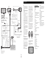
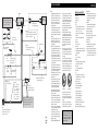
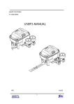
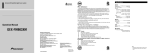
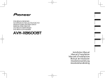
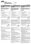
Installation
Note:
DEH-2330R
DEH-2300R
DEH-2300RB
DEH-1330R
DEH-1300R
This product conforms to new cord colors.
Los colores de los cables de este producto se conforman con un nuevo código de colores.
Dieses Gerät entspricht den neuen kabelfarben.
Le code de couleur des câbles utilisé pour ce produit
est nouveau.
Questo prodotto è conforme ai nuovi codici colori.
De kleuren van de snoeren van dit toestel zijn gewijzigd.
Printed in Portugal
Imprimé au Portugal
<URD-165-A> EW
<KKYLL/00G00000>
MANUEL D’INSTALLATION
INSTALLATION MANUAL
•
5
•
•
60°
•
•
•
Fig. 1
Abb. 1
Afb. 1
2
1
182
53
3
4
Fig. 2
Abb. 2
Afb. 2
Fig. 3
Abb. 3
Afb. 3
Before finally installing the unit, connect the
wiring temporarily, making sure it is all connected up properly, and the unit and the system work
properly.
Use only the parts included with the unit to
ensure proper installation. The use of unauthorized parts can cause malfunctions.
Consult with your nearest dealer if installation
requires the drilling of holes or other modifications of the vehicle.
Install the unit where it does not get in the driver’s way and cannot injure the passenger if there
is a sudden stop, like an emergency stop.
The semiconductor laser will be damaged if it
overheats, so don’t install the unit anywhere hot
— for instance, near a heater outlet.
If installation angle exceeds 60° from horizontal,
the unit might not give its optimum performance.
(Fig. 1)
Installation with the rubber bush
(Fig. 2)
1. Dashboard
2. Holder
After inserting the holder into the dashboard,
then select the appropriate tabs according to the
thickness of the dashboard material and bend
them.
(Install as firmly as possible using the top and
bottom tabs. To secure, bend the tabs 90
degrees.)
3. Rubber bush
4. Screw
<ENGLISH>
Removing the Unit (Fig. 3)
Instalación
Nota:
•
5. Insert the supplied extraction keys into the unit,
as shown in the figure, until they click into place.
Keeping the keys pressed against the sides of the
unit, pull the unit out.
•
•
•
•
•
Antes de instalar definitivamente la unidad,
conecte temporalmente el cableado, asegurándose
de que todo está convenientemente conectado y
tanto la unidad como el sistema funcionan correctamente.
Utilice únicamente los componentes que se
incluyen con la unidad para garantizar una adecuada instalación. El uso de componentes no
autorizados puede hacer que la unidad no funcione correctamente.
Consulte a su distribuidor más próximo si la
instalación requiere la perforación de orificios u
otras modificaciones en el vehículo.
Instale la unidad donde no estorbe al conductor y
no pueda producir daños al pasajero si se produjera una parada repentina; por ejemplo una parada en una situación de emergencia.
El láser del semiconductor se dañará si se sobrecalienta; por tanto, no instale la unidad en una
posición en que pueda calentarse — (por ejemplo, cerca de un orificio de salida de la calefacción).
Si el ángulo de instalación pasa de 60º respecto a
la horizontal, el rendimiento de la unidad no será
óptimo. (Fig. 1)
Instalación con la arandela de
caucho (Fig. 2)
1. Salpicadero
2. Soporte
Una vez insertado el soporte en el salpicadero,
seleccione las pestañas correspondientes según el
grosor del material del salpicadero y dóblelas.
(Instale la unidad lo más firme posible utilizando
las pestañas inferiores y superiores. Para fijarla,
doble las pestañas 90 grados.)
3. Arandela de caucho
4. Tornillo
<ESPAÑOL>
Retirar la unidad (Fig. 3)
5. Inserte en la unidad las llaves de extracción suministradas, como se muestra en la figura, hasta
que suene un “clic” indicando que están en la
posición correcta. Con las llaves presionadas
contra los laterales de la unidad, tire de la unidad
hacia el exterior.
Einbau
Hinweis:
•
•
•
•
•
•
Schließen Sie vor dem Einbau alle Kabel
vorübergehend an und kontrollieren Sie die
Anschlüsse auf Richtigkeit. Überprüfen sind
dann die Funktion des Geräts und Systems.
Zum Einbau ausschließlich die mitgelieferten
Teile verwenden, um eine korrekte Montage zu
gewährleisten. Die Verwendung von Teilen
anderen Ursprungs kann Störungen zur Folge
haben.
Falls für den Einbau Löcher zu bohren oder
Änderungen am Fahrzeug vorzunehmen sind,
sollten Sie zuvor Ihren Fachhändler befragen.
Das Gerät an einer Stelle einbauen, wo es weder
den Fahrer behindert noch den Beifahrer beim
Bremsen verletzen kann.
Der Halbleiterlaser wird durch Überhitzung
beschädigt. Daher das Gerät keinesfalls an einer
Stelle einbauen, wo es heiß werden kann, wie z.
B. in der Nähe von Heizungsauslässen.
Falls der Einbauwinkel 60° von der Horizontalen
überschreitet, arbeitet das Gerät unter Umständen
nicht optimal. (Abb. 1)
Einbau mit Gummibuchse
(Abb. 2)
1. Armaturenbrett
2. Einbaukonsole
Nach Einführen der Einbaukonsole in das
Armaturenbrett deren Haltezungen von der Dicke
des Armaturenbretts hineindrücken.
(Die Einbaukonsole mit den oberen und unteren
Zungen sicher befestigen. Zum Sichern die
Haltezunge 90° biegen.)
3. Gummibuchse
4. Schraube
<DEUTSCH>
Entnahme des Geräts (Abb. 3)
Installation
Remarque:
•
5. Die beiliegenden Ausziehschlüssel entsprechend
der Abbildung in das Gerät einrasten. Die
Schlüssel gegen die Seiten des Geräts drücken
und das Gerät herausziehen.
•
•
•
•
•
Avant de terminer l’installation de l’appareil,
branchez temporairement les câbles en veillant à
ce que tous les câbles soient correctement connectés et que l’appareil et la chaîne fonctionnent
parfaitement.
Utilisez uniquement les pièces fournies avec l’appareil de manière à en garantir une installation
conforme. L’utilisation de pièces non autorisées
peut provoquer des dysfonctionnements.
Consultez votre revendeur si l’installation
requiert le perçage de trous ou d’autres modifications sur le véhicule.
Installez l’appareil à un endroit où il ne risque
pas de gêner ni de blesser le passager en cas d’arrêt brutal, par exemple lors d’un freinage en
urgence.
Le laser à semi-conducteur risque d’être endommagé en cas de surchauffe; aussi, ne l’installez
pas à des endroits chauds — comme à proximité
d’une bouche de chauffage.
Si l’angle d’installation dépasse 60° par rapport à
l’horizontale, l’appareil risque de ne pas fournir
de performances optimales. (Fig. 1)
<FRANÇAIS>
Retrait de l’appareil (Fig. 3)
5. Insérez les clés d’extraction fournies dans l’appareil comme illustré dans la figure jusqu’à ce
qu’elles s’encliquettent. Tout en maintenant les
clés contre les sections latérales de l’appareil,
extrayez celui-ci.
Installazione
Nota:
•
•
•
•
•
•
Prima di installare l’apparecchio in modo definitivo, collegare i cavi in modo provvisorio, per
accertare che tutto sia collegato correttamente, e
che l’apparecchio e il sistema funzionino perfettamente.
Per garantire un’installazione corretta, usare solo
le parti fornite insieme all’apparecchio.
L’impiego di parti non approvate può causare
difetti di funzionamento.
Rivolgersi al rivenditore più vicino per informazioni, se l’installazione richiede l’esecuzione
di fori o altre modifiche alla vettura.
Installare l’apparecchio in una posizione in cui
non intralci il conducente e non possa causare
danni al passeggero in caso di arresto improvviso, come un arresto d’emergenza.
Il laser a semiconduttore può essere danneggiato
dal surriscaldamento, quindi non installare l’apparecchio in punti molto caldi — per esempio in
vicinanza di una bocchetta di riscaldamento.
Se l’angolo di installazione supera 60º dall’orizzontale, è possibile che l’apparecchio non fornisca le migliori prestazioni. (Fig. 1)
Installation avec le manchon en
caoutchouc (Fig. 2)
Installazione con boccola di
gomma (Fig. 2)
1. Tableau de bord
2. Support
Après avoir introduit le support dans le tableau
de bord, sélectionnez les pattes appropriées en
fonction de l’épaisseur du matériau du tableau de
bord et repliez-les.
(Installez-le aussi fermement que possible à
l’aide des pattes supérieure et inférieure. Pour le
fixer en position, repliez les pattes de 90 degrés.)
3. Manchon en caoutchouc
4. Vis
1. Plancia
2. Supporto
Dopo aver inserito il supporto nella plancia,
scegliere le linguette appropriate in base allo
spessore della plancia e piegarle.
(Installare saldamente servendosi delle linguette
superiori ed inferiori. Per fissare, piegare le
linguette a 90 gradi.)
3. Boccola di gomma
4. Vite
<ITALIANO>
Rimozione dell’apparecchio (Fig. 3)
5. Inserire nell’apparecchio i dispositivi di
estrazione in dotazione, come mostrato in figura,
fino a quando s’innestano in posizione. Estrarre
l’apparecchio tenendo premuti i dispositivi contro
i lati e tirando.z
Montage
Opmerking:
•
•
•
•
•
•
Sluit de draden tijdelijk aan en controleer of alles
goed is aangesloten en het toestel en het systeem
correct werken alvorens het toestel definitief te
monteren.
Gebruik met het oog op een degelijke montage
alleen de bij dit toestel geleverde onderdelen. Het
gebruik van niet-goedgekeurde onderdelen kan
defecten veroorzaken.
Neem contact op met uw dichtstbijzijnde handelaar als voor de montage gaten moeten worden
geboord of andere wijzigingen aan het voertuig
nodig zijn.
Monteer het toestel op een plaats waar het de
bestuurder niet kan hinderen en geen passagiers
kan verwonden bij een bruuske stopbeweging,
bijvoorbeeld in een noodgeval.
Aangezien de halfgeleiderlaser zal worden
beschadigd in geval van oververhitting, mag u het
toestel niet monteren in de buurt van een warmtebron,—bijvoorbeeld dicht bij een verwarmingsuitlaat.
Als het toestel wordt gemonteerd in een hoek van
meer dan 60º ten opzichte van de horizontale
positie, zal het toestel mogelijk niet optimaal
werken. (Afb. 1)
Montage met behulp van de rubberbus(Afb. 2)
1. Dashboard
2. Houder
Plaats de houder in het dashboard en kies vervolgens de geschikte lipjes, overeenkomstig de dikte
van het dashboardmateriaal, en buig ze.
(Monteer zo stevig mogelijk met de bovenste en
onderste lipjes. Om de lipjes vast te zetten, buigt
u ze 90 graden.)
3. Rubberbus
4. Schroef
<NEDERLANDS>
Verwijderen van het toestel (Afb. 3)
5. Steek de meegeleverde uittreksleutels in het toestel, zoals getoond op de afbeelding, tot ze vastklikken. Houd de sleutels tegen de zijkanten van
het toestel gedrukt en trek het toestel naar buiten.
Connecting the Units
<ENGLISH>
Note:
•
3. Antenna jack
17. Yellow/black
If you use a cellular telephone, connect it via the Audio
Mute lead on the cellular telephone. If not, keep the Audio
Mute lead free of any connections.
2*
6. Connect leads of the
same color to each other.
4*
•
•
•
7. Cap (1*)
When not using this terminal,
do not remove the cap.
19. System remote control
18. Blue/white
To system control terminal of the power amp
(max. 300 mA 12 V DC).
•
8. Yellow (3*)
9. Yellow (2*)
Back-up
To terminal always supplied
(or accessory)
with power regardless of
ignition switch position.
+
≠
≠
•
25.
The pin position of the ISO connector will differ
depends on the type of vehicle. Connect 6* and 7*
when Pin 5 is an antenna control type. In another
type of vehicle, never connect 6* and 7*.
13.ISO connector
Note:
In some vehicles, the ISO connector may be
divided into two. In this case, be sure to
connect to both connectors.
Fig. 4
Abb. 4
Afb. 4
AC C
O
ACC position
F
O
STAR
24. Blue/white (7*)
To Auto-antenna relay control
terminal (max. 300 mA 12 V DC).
F
N
23. Blue/white (6*)
•
•
STAR
•
22. Perform these connections when using
a different amp (sold separately).
14.Speaker leads
White
: Front left +
White/black : Front left ≠
Gray
: Front right +
Gray/black : Front right ≠
Green
: Rear left +
Green/black : Rear left ≠
Violet
: Rear right +
Violet/black : Rear right ≠
•
•
11. Red (4*)
To electric terminal controlled
by ignition switch (12 V DC)
ON/OFF.
12. Black (ground)
To vehicle (metal) body.
21.Rear speaker (Right)
+
•
N
10. Red (5*)
Accessory
(or back-up)
20.Rear speaker (Left)
•
When this product’s source is switched ON, a
control signal is output through the blue/white
lead. Connect to an external power amp’s system
remote control or the car’s Auto-antenna relay
control terminal (max. 300 mA 12 V DC). If the
car features a glass antenna, connect to the antenna booster power supply terminal.
When an external power amp is being used with
this system, be sure not to connect the blue/white
lead to the amp’s power terminal. Likewise, do
not connect the blue/white lead to the power terminal of the auto-antenna. Such connection could
cause excessive current drain and malfunction.
To avoid short-circuiting, cover the disconnected
lead with insulating tape. Especially, insulate the
unused speaker leads without fail. There is a possibility of short-circuiting if the leads are not
insulated.
If this unit is installed in a vehicle that does not
have an ACC (accessory) position on the ignition
switch, the red lead of the unit should be connected to a terminal coupled with ignition switch
ON/OFF operations. If this is not done, the vehicle battery may be drained when you are away
from the vehicle for several hours.
OF
5*
15. Connecting cords with
RCA pin plugs (sold separately).
•
OF
4. Fuse
1*
3*
16. Power amp
(sold separately)
2. Rear output
This unit is for vehicles with a 12-volt battery
and negative grounding. Before installing it in a
recreational vehicle, truck, or bus, check the battery voltage.
To avoid shorts in the electrical system, be sure
to disconnect the ≠ battery cable before beginning installation.
Refer to the owner’s manual for details on connecting the power amp and other units, then
make connections correctly.
Secure the wiring with cable clamps or adhesive
tape. To protect the wiring, wrap adhesive tape
around them where they lie against metal parts.
Route and secure all wiring so it cannot touch
any moving parts, such as the gear shift, handbrake and seat rails. Do not route wiring in
places that get hot, such as near the heater outlet.
If the insulation of the wiring melts or gets torn,
there is a danger of the wiring short-circuiting to
the vehicle body.
Don’t pass the yellow lead through a hole into
the engine compartment to connect to the battery.
This will damage the lead insulation and cause a
very dangerous short.
Do not shorten any leads. If you do, the protection circuit may fail to work when it should.
Never feed power to other equipment by cutting
the insulation of the power supply lead of the
unit and tapping into the lead. The current capacity of the lead will be exceeded, causing overheating.
When replacing fuse, be sure to use only fuse of
the rating prescribed on this unit.
Since a unique BPTL circuit is employed, never
wire so the speaker leads are directly grounded
or the left and right ≠ speaker leads are common.
Speakers connected to this unit must be highpower types with minimum rating of 45 W (50
W)* and impedance of 4 to 8 ohms. Connecting
speakers with output and/or impedance values
other than those noted here may result in the
speakers catching fire, emitting smoke, or
becoming damaged.
*DEH-2330R, DEH-2300R and DEH-2300RB
T
5. Note:
Depending on the kind of vehicle, the functio
of 3* and 5* may be different. In this case, be
sure to connect 2* to 5* and 4* to 3*.
•
T
1. This product
No ACC position
•
The black lead is ground. Please ground this lead
separately from the ground of high-current products such as power amps.
If you ground the products together and the
ground becomes detached, there is a risk of damage to the products or fire.
•
Cords for this product and those for other products may be different colors even if they have the
same function. When connecting this product to
another product, refer to the supplied Installation
manuals of both products and connect cords that
have the same function.
Connection Diagram (Fig. 4)
1.
2.
3.
4.
5.
This product
Rear output
Antenna jack
Fuse
Note:
Depending on the kind of vehicle, the function of
3* and 5* may be different. In this case, be sure
to connect 2* to 5* and 4* to 3*.
6. Connect leads of the same color to each other.
7. Cap (1*)
When not using this terminal, do not remove the
cap.
8. Yellow (3*)
Back-up (or accessory)
9. Yellow (2*)
To terminal always supplied with power regardless of ignition switch position.
10. Red (5*)
Accessory (or back-up)
11. Red (4*)
To electric terminal controlled by ignition switch
(12 V DC) ON/OFF.
12. Black (ground)
To vehicle (metal) body.
13. ISO connector
Note:
In some vehicles, the ISO connector may be
divided into two. In this case, be sure to connect
to both connectors.
14. Speaker leads
White: Front left +
White/black: Front left ≠
Gray: Front right +
Gray/black: Front right ≠
Green: Rear left +
Green/black: Rear left ≠
Violet: Rear right +
Violet/black: Rear right ≠
15. Connecting cords with RCA pin plugs (sold separately).
16. Power amp (sold separately)
17. Yellow/black
If you use a cellular telephone, connect it via the
Audio Mute lead on the cellular telephone. If not,
keep the Audio Mute lead free of any connections.
18. Blue/white
To system control terminal of the power amp
(max. 300 mA 12 V DC).
19. System remote control
20. Rear speaker (Left)
21. Rear speaker (Right)
22. Perform these connections when using a different
amp (sold separately).
23. Blue/white (6*)
24. Blue/white (7*)
To Auto-antenna relay control terminal (max.
300 mA 12 V DC).
25. The pin position of the ISO connector will differ
depends on the type of vehicle. Connect 6* and 7*
when Pin 5 is an antenna control type. In another
type of vehicle, never connect 6* and 7*.
Conexión de las unidades
<ESPAÑOL>
Nota:
•
3. Antenna jack
3*
2*
5*
4*
17. Yellow/black
If you use a cellular telephone, connect it via the Audio
Mute lead on the cellular telephone. If not, keep the Audio
Mute lead free of any connections.
6. Connect leads of the
same color to each other.
•
7. Cap (1*)
When not using this terminal,
do not remove the cap.
19. System remote control
18. Blue/white
To system control terminal of the power amp
(max. 300 mA 12 V DC).
8. Yellow (3*)
9. Yellow (2*)
Back-up
To terminal always supplied
(or accessory)
with power regardless of
ignition switch position.
10. Red (5*)
Accessory
(or back-up)
•
20.Rear speaker (Left)
11. Red (4*)
To electric terminal controlled
by ignition switch (12 V DC)
ON/OFF.
21.Rear speaker (Right)
+
+
≠
≠
•
•
24. Blue/white (7*)
To Auto-antenna relay control
terminal (max. 300 mA 12 V DC).
•
25.
•
The pin position of the ISO connector will differ
depends on the type of vehicle. Connect 6* and 7*
when Pin 5 is an antenna control type. In another
type of vehicle, never connect 6* and 7*.
13.ISO connector
Note:
In some vehicles, the ISO connector may be
divided into two. In this case, be sure to
connect to both connectors.
•
Fig. 4
Abb. 4
Afb. 4
F
AC C
O
Posición ACC
F
O
STAR
23. Blue/white (6*)
•
N
14.Speaker leads
White
: Front left +
White/black : Front left ≠
Gray
: Front right +
Gray/black : Front right ≠
Green
: Rear left +
Green/black : Rear left ≠
Violet
: Rear right +
Violet/black : Rear right ≠
•
•
STAR
22. Perform these connections when using
a different amp (sold separately).
•
N
12. Black (ground)
To vehicle (metal) body.
•
Si la fuente de este producto está encendida
(ON), se emitirá una señal de control a través del
cable azul/blanco. Conéctelo al terminal de control remoto del amplificador de potencia externo
o al terminal de control de relé de la antena del
automóvil (máx. 300 mA 12 V CC). Si el
automóvil tiene una antena de fibra de vidrio,
conéctela al terminal de la fuente de alimentación
del amplificador de la antena.
Si utiliza un amplificador de potencia externo
con este sistema, asegúrese de no conectar el
cable azul/blanco al terminal de alimentación del
amplificador. De igual modo, no conecte el cable
azul/blanco al terminal de alimentación de la
antena del automóvil. Esta conexión podría
provocar un consumo excesivo de corriente y
funcionar mal.
Para evitar cortocircuitos, cubra el cable pelado
con cinta aislante. Especialmente, no deje de aislar los cables de los altavoces que no se utilicen.
Si los cables no están aislados, puede producirse
un cortocircuito.
Si esta unidad se instala en un vehículo que no
tenga una posición ACC (accesorio) en el interruptor de encendido, el cable rojo de la unidad debe
conectarse a un terminal que esté asociado con el
interruptor de encendido (ON/OFF). Si no se hace
así, la batería del vehículo podría descargarse si
permanece varias horas fuera del vehículo.
OF
4. Fuse
1*
15. Connecting cords with
RCA pin plugs (sold separately).
•
OF
16. Power amp
(sold separately)
2. Rear output
Esta unidad está diseñada para vehículos con una
batería de 12 voltios y toma de tierra negativa.
Antes de instalarla en un vehículo recreativo, un
camión o un autobús, compruebe el voltaje.
Para evitar cortocircuitos, asegúrese de que
desconecta el ≠ cable de la batería antes de
comenzar la instalación.
Consulte el manual del usuario si desea información adicional sobre el procedimiento para
conectar el amplificador de potencia y las demás
unidades; a continuación, haga correctamente las
conexiones.
Fije el cableado con mordazas para cable o cinta
adhesiva. Para proteger el cableado, forre con
cinta adhesiva los cables donde rocen con componentes metálicos.
Dirija y fije todo el cableado de modo que no
roce con ningún componente móvil (por ejemplo,
la palanca de cambios, el freno de mano o los
carriles de deslizamiento del asiento). No lleve el
cableado por posiciones que se calienten (por
ejemplo cerca de un orificio de salida de la calefacción). Si el aislamiento del cableado se funde
o se rasga, podría provocar un cortocircuito en la
carrocería del vehículo.
No pase el cable amarillo a través de un orificio
en el compartimento del motor para conectarlo a
la batería. Podría dañarse el aislamiento del cable
y provocar un cortocircuito muy peligroso.
No acorte ningún cable. Si lo hace, el circuito de
protección podría dejar de funcionar en el
momento necesario.
No facilite alimentación a otro equipo cortando
el aislamiento del cable de la fuente de alimentación de la unidad y empalmando el cable.
La capacidad de corriente del cable podría
sobrepasarse, produciendo calentamiento.
Cuando sustituya un fusible, asegúrese de que
utiliza únicamente un fusible con el amperaje
prescrito en esta unidad.
Como se emplea un único circuito BPTL, no
instale nunca el cableado de modo que los cables
de los altavoces estén conectados directamente a
tierra o que los cables de los altavoces derecho e
izquierdo ≠ sean comunes.
Los altavoces conectados a esta unidad deben ser
de alta potencia, como mínimo de 45 W (50 W)*,
y una impedancia de 4 a 8 ohmios.
Si se conectan altavoces con otros valores de
potencia de salida y/o impedancia que los prescritos en este manual, puede que se quemen,
emitan humo o se dañen.
*DEH-2330R, DEH-2300R y DEH-2300RB
T
5. Note:
Depending on the kind of vehicle, the functio
of 3* and 5* may be different. In this case, be
sure to connect 2* to 5* and 4* to 3*.
•
T
1. This product
Sin posición ACC
•
El cable negro es la toma de tierra. Conecte a
tierra este cable por separado; es decir, a otra
toma de tierra que no sea la de los productos de
alta corriente (por ejemplo los amplificadores de
potencia).
Si los productos se conectaran juntos a tierra y
esa toma de tierra se soltara, existiría el riesgo de
que se dañaran o incluso que se incendiaran.
•
Los cables para esta unidad y aquéllas para las
unidades pueden ser de colores diferentes aun si
tienen la misma función. Cuando se conecta esta
unidad a otra, refiérase a los manuales de instalación de ambas unidades y conecte los cables
que tienen la misma función.
Diagrama de conexión (Fig. 4)
1.
2.
3.
4.
5.
Esta unidad
Salida posterior
Toma de antena
Fusible
Nota:
Según el tipo de vehículo, la función de 3* y 5*
puede ser diferente. En este caso, asegúrese de
conectar el 2* al 5* y el 4* al 3*.
6. Conecte entre sí los cables del mismo color.
7. Cubierta (1*)
Cuando no utilice este terminal, no quite la
cubierta.
8. Amarillo (3*)
Reserva (o accesorio)
9. Amarillo (2*)
Al terminal que se encuentra siempre bajo tensión, independientemente de la posición del interruptor de encendido.
10. Rojo (5*)
Accesorio (o de reserva)
11. Rojo (4*)
Al terminal eléctrico controlado por el interruptor
de encendido (12 V CC) ON/OFF.
12. Negro (tierra)
A la carrocería (metal) del vehículo.
13. Conector ISO
Nota:
En algunos vehículos, el conector ISO puede
estar dividido en dos. En este caso, asegúrese de
conectar ambos conectores.
14. Cables de los altavoces
Blanco: Anterior izquierdo +
Blanco/negro: Anterior izquierdo ≠
Gris: Anterior derecho +
Gris/negro: Anterior derecho ≠
Verde: Posterior izquierdo +
Verde/negro: Posterior izquierdo ≠
Violeta: Posterior derecho +
Violeta/negro: Posterior derecho ≠
15. Conexión de cables con enchufes de patillas
RCA (vendidos por separado).
16. Amplificador de potencia (vendido por separado)
17. Amarillo/negro
Si utiliza un teléfono móvil, conéctelo a través
del cable Audio Mute del teléfono móvil. En caso
contrario, no conecte el cable Audio Mute a
ningún terminal.
18. Azul/blanco
Al terminal de control del sistema del amplificador de potencia (máx. 300 mA 12 V CC).
19. Control remoto del sistema
20. Altavoz posterior (Izquierdo)
21. Altavoz posterior (Derecho)
22. Haga estas conexiones cuando utilice otro amplificador (vendido por separado).
23. Azul/blanco (6*)
24. Azul/blanco (7*)
Al terminal de control de relé de la antena del
automóvil (máx. 300 mA 12 V CC).
25. La posición de las patillas del conector ISO puede
ser diferente según el tipo de vehículo. Conecte 6*
y 7* si la Patilla 5 es de tipo control de antena. En
otro tipo de vehículo, no conecte nunca 6* y 7*.
Kabel dieses Geräts und die anderer Geräte können unterschiedliche Farben haben, auch wenn
sie die gleichen Funktionen haben. Beim
Anschluß dieses Geräts an ein anderes Gerät
unter Bezugnahme auf die mit beiden Geräten
mitgelieferten Installationsanleitungen die Kabel
mit derselben Funktion verbinden.
•
•
•
•
•
•
•
•
•
•
•
•
•
Lorsque cet appareil source est commuté sur ON, un
signal de commande est transmis via le fil bleu/blanc.
Raccordez-le à la télécommande d’un système d’amplification de puissance externe ou à la prise de commande du relais de l’antenne de la voiture (max. 300
mA 12 V DC). Si la voiture est équipée d’une
antenne intégrée dans une vitre, raccordez-le à la
prise d’alimentation de l’amplificateur d’antenne.
Si vous utilisez un amplificateur externe avec cet
appareil, ne raccordez pas le fil bleu/blanc à la
prise d’alimentation de l’amplificateur. De même,
ne raccordez pas le fil bleu/blanc à la prise d’alimentation de l’antenne automatique. Une telle
connexion peut entraîner une consommation de
courant excessive et un dysfonctionnement.
Pour éviter les courts-circuits, recouvrez le fil
déconnecté de bande isolante. En particulier,
isolez correctement les fils de haut-parleur inutilisés. Il y a un risque de court-circuit si les fils ne
sont pas isolés.
Si cet appareil est installé dans un véhicule dont
le contact n’est pas doté d’une position ACC
(accessoires), le fil rouge de l’appareil doit être
branché sur une prise couplée avec la commutation marche/arrêt (ON/OFF) du contact. Si ce
n’est pas fait, la batterie du véhicule risque de
s’épuiser si vous quittez le véhicule pendant
quelques heures.
F
AC C
O
Position ACC
F
O
STAR
Das schwarze Kabel ist das Erdungskabel. Dieses
Kabel ist getrennt vom Masseanschluss von
Hochstromgeräten wie Leistungsverstärkern zu erden.
Falls die Geräte gemeinsam geerdet werden und sich
der Masseanschluss lösen sollte, können Schäden an
den Geräten und sogar Brand resultieren.
•
Cet appareil est conçu pour les véhicules équipés
d’une batterie de 12 volts et d’une masse négative.
Avant de l’installer dans un véhicule de loisirs, un
camion ou un bus, vérifiez la tension de la batterie.
Pour éviter les courts-circuits dans le système
électrique, débranchez le fil de la batterie ≠
avant d’entamer l’installation.
Reportez-vous au mode d’emploi pour plus de
détails sur le raccordement à l’amplificateur de
puissance et à d’autres appareils, puis établissez
les connexions correctement.
Fixez les fils à l’aide de serre-fil ou de bande
adhésive. Pour protéger les fils, enroulez-les de
bande adhésive aux endroits où ils sont en contact avec des pièces métalliques.
Cheminez et fixez tous les fil de façon à ce qu’ils
n’entrent pas en contact avec des pièces mobiles,
comme le levier du changement de vitesses, le
frein à main ou les rails des sièges. Ne cheminez
pas les fils à des endroits chauds comme à proximité des bouches de chauffage. Si la gaine
isolante des fils fond ou se déchire, les fils
risquent d’être en court-circuit avec la carrosserie
du véhicule.
Ne faites pas passer le fil jaune par un orifice dans le
compartiment moteur pour le raccorder à la batterie.
Cela risque d’endommager la gaine isolante du fil et
de provoquer un court-circuit très dangereux.
Ne mettez aucun fil en court-circuit. Sinon, le
circuit de protection risque de ne pas fonctionner
lorsqu’il le devrait.
N’alimentez en aucun cas un autre équipement
en découpant la gaine isolante du fil d’alimentation et en puisant du courant sur le fil. La capacité de courant du fil risque d’être dépassée,
provoquant ainsi une surchauffe.
Lors du remplacement du fusible, utilisez uniquement un fusible de l’intensité prescrite sur cet
appareil.
Etant donné qu’un seul circuit BPTL est utilisé,
n’établissez jamais le câblage de façon à mettre
directement les fils des haut-parleurs à la masse
et n’utilisez pas de fil commun pour les haut-parleurs gauche et droit ≠.
Les haut-parleurs raccordés à cet appareil doivent
être de type à grande puissance avec une puissance nominale minimale de 45 W (50 W)* et
une impédance de 4 à 8 ohms.
Le raccordement de haut-parleurs offrant une
puissance de sortie et une impédance différentes
des valeurs prescrites peut entraîner un début
d’incendie, des émissions de fumée ou des dommages aux haut-parleurs.
*DEH-2330R, DEH-2300R et DEH2300RB
N
•
Ohne ACC-Position
•
STAR
•
O
STAR
ACC-Position
F
N
•
O
STAR
•
AC C
N
•
F
Dieses Gerät
Ausgang für Hecklautsprecher
Antennenbuchse
Sicherung
Hinweis:
Je nach Fahrzeug können 3* und 5* unterschiedliche Funktionen aufweisen. In diesem Fall
2* mit 5* und 4* mit 3* verbinden.
6. Kabel gleicher Farbe miteinander verbinden.
7. Kappe (1*)
Diese Kappe nicht entfernen, falls der Anschluss
nicht beschaltet wird.
8. Gelb (3*)
Reserve (oder Zubehör)
9. Gelb (2*)
An eine Klemme anschließen, an der ungeachtet
der Zündschalterstellung stets Strom anliegt.
10. Rot (5*)
Zubehör (oder Reserve)
11. Rot (4*)
An eine Zündschalterklemme (12 V
Gleichspannung) anschließen, die mit dem Ein/Ausschalten der Zündung gekoppelt ist.
12. Schwarz (Masse)
An Karosserie (Metallteil)
13. ISO-Auschluß
Hinweis:
Bei manchen Fahrzeugen kann der ISO-Auschluß
in zwei Stecker aufgeteilt sein. In diesem Fall
unbedingt beide Stecker anschließen.
14. Lautsprecherkabel
Weiß: Vorn links +
Weiß/schwarz: Vorn links ≠
Grau: Vorn rechts +
Grau/schwarz: Vorn rechts ≠
Grün: Hinten links +
Grün/schwarz: Hinten links ≠
Violett: Hinten rechts +
Violett/schwarz: Hinten rechts ≠
15. Mit RCA-Stiftsteckerkabeln verbinden (getrennt
erhältlich).
16. Leistungsverstärker (getrennt erhältlich)
Remarque:
N
•
1.
2.
3.
4.
5.
17. Gelb/schwarz
Bei Fahrzeugen mit Funktelefon oder
Freisprechanlage mit deren
Stummschaltungsanschluss oder -kabel (AUDIO
MUTE) verbinden. Falls kein Funktelefon etc.
installiert ist, das Stummschaltungskabel nirgendwo anschließen.
18. Blau/weiß
An Systemsteuerungsanschluss des
Leistungsverstärkers (max. 300 mA, 12 V
Gleichspannung).
19. Systemfernsteuerung
20. Hecklautsprecher (links)
21. Hecklautsprecher (rechts)
22. Diese Anschlüsse bei Verwendung eines separaten Verstärkers (getrennt erhältlich) ausführen.
23. Blau/weiß (6*)
24. Blau/weiß (7*)
An Antennenheberrelais-Steueranschluss (max.
300 mA, 12 V Gleichspannung).
25. Die Kontaktstiftbelegung von ISO-Auschluß vom
Fahrzeugtyp ab. Falls Kontaktstift 5 zur
Antennenhebersteuerung dient, 6* und 7*
anschließen. Bei anderen Fahrzeugen 6* und 7*
niemals anschließen.
OF
•
•
Anschlussplan (Abb. 4)
OF
•
•
OF
•
•
OF
•
Beim Einschalten einer Programmquelle in
diesem Gerät wird ein Steuersignal über das
blau/weiße Kabel ausgegeben. Verbinden Sie es
mit dem Fernsteuerungseingang eines
Leistungsverstärkers oder mit dem
Antennenheber-Steueranschluss (max. 300 mA,
12 V Gleichspannung) des Fahrzeugs. Falls das
Fahrzeug mit einer Scheibenantenne ausgestattet
ist, das Kabel mit dem AntennenverstärkerStromversorgungsanschluss verbinden.
Falls ein separater Leistungsverstärker im System
verwendet wird, sollten Sie darauf achten, dass
Sie das blau/weiße Kabel nicht versehentlich an
der Stromversorgungsbuchse des Verstärkers
anschließen. Gleichermaßen darf das blau/weiße
Kabel nicht mit dem Stromversorgungsanschluss
des Antennenhebers angeschlossen werden.
Solche Fehler können eine übermäßige
Stromentnahme und Störungen verursachen.
Zur Vermeidung von Kurzschlüssen gelöste
Kabel mit Isolierband umwickeln. Unbedingt
unbenutzte Lautsprecherkabel isolieren. Falls die
Kabel nicht isoliert werden, besteht Gefahr von
Kurzschlüssen.
Falls das Gerät in ein Fahrzeug eingebaut wird,
dessen Zündschalter keine ACC-Position
(Nebenverbraucher) besitzt, sollten Sie das rote
Kabel des Geräts an eine andere Klemme
anschließen, die mit dem Ein-/Ausschalten der
Zündung gekoppelt ist. Anderenfalls kann sich
die Batterie bei abgestelltem Motor innerhalb
weniger Stunden entladen.
T
•
•
T
•
Dieses Gerät ist auf Fahrzeuge mit 12-V-Batterie
und negativer Erdung (Minuspol an Masse) ausgelegt. Vor dem Einbau in Wohnmobile, LKWs
oder Busse die Batteriespannung prüfen.
Unbedingt das Massekabel ≠ der Batterie vor
der Montage abklemmen, um Kurzschlüsse im
elektrischen System auszuschließen.
Lesen Sie die Einzelheiten zum Anschluss des
Leistungsverstärkers und anderer Komponenten
in der Bedienungsanleitung bevor Sie die
Anschlüsse vornehmen, um Fehler zu vermeiden.
Die Kabel mit Kabelklemmen oder Klebeband
sichern. Zum Schutz der Kabel sollten Sie sie an
den Stellen, an denen Sie Metallteile berühren
mit Klebeband umwickeln.
Verlegen und befestigen Sie alle Kabel so, dass
sie keine beweglichen Teile wie Schalthebel,
Handbremshebel und Sitzschienen berühren. Die
Kabel dürfen nicht an heiß werdenden Bereichen
wie z. B. Heizungsauslässe entlanggeführt werden. Falls die Isolierung von Kabeln schmilzt
oder durchgescheuert wird, besteht Gefahr von
Kurzschlüssen mit der Karosserie.
Das gelbe Kabel zum Anschluss an die Batterie
keinesfalls durch ein Loch in den Motorraum
führen. Dadurch würde die Isolierung beschädigt,
was einen gefährlichen Kurzschluss zur Folge hat.
Verkürzen Sie niemals Kabel. Dadurch könnte
die Schutzschaltung nicht ansprechen, wenn es
erforderlich ist.
Niemals zur Stromversorgung anderer Geräte die
Isolierung am Stromversorgungskabel des Geräts
abschneiden und davon Strom abzapfen. Dadurch
wird die Strombelastbarkeit des Kabels überschritten, was Überhitzung zur Folge hat.
Als Ersatzsicherung dürfen nur solche mit dem
vorgeschriebenen Nennwert verwendet werden.
Aufgrund des speziellen BPTL-Schaltkreises dürfen Lautsprecherkabel niemals direkt geerdet
oder die Minuskabel ≠ von linkem und rechtem
Kanal verbunden werden.
Die Lautsprecher, die an dieses Gerät
angeschlossen werden, müssen auf eine
Mindestnennleistung von 45 W (50 W)* und eine
Impedanz von 4 bis 8 Οhm ausgelegt sein.
Falls Lautsprecher mit anderen Leistungsund/oder Impedanzwerten angeschlossen werden,
können die Lautsprecher in Brand geraten, Rauch
entwickeln oder beschädigt werden.
*DEH-2330R, DEH-2300R und DEH-2300RB
<FRANÇAIS>
T
Hinweis:
•
Raccordement des appareils
<DEUTSCH>
T
Anschließen der Geräte
Pas de position ACC
•
Le fil noir est la masse. Raccordez ce fil à un
autre point de masse que les équipements gros
consommateurs de courant tels que des amplificateurs de puissance.
Si vous mettez les équipements ensemble à la
masse et si le fil se détache du point de masse, il
y a un risque de dommages pour ces équipements
voire d’incendie.
•
Les câbles de cet appareil et ceux d’autres
appareils peuvent fort bien ne pas être de la
même couleur bien que remplissant la même
fonction. Pour relier cet appareil à un autre
appareil, utilisez le manuel d’installation de chacun et effectuez les raccordements en ne tenant
compte que de la fonction de chaque câble.
Diagramme de connexion (Fig. 4)
1.
2.
3.
4.
5.
Cet appareil
Sortie arrière
Prise d’antenne
Fusible
Remarque:
Suivant le type de véhicule, la fonction des points
3* et 5* peut être différente. Dans ce cas, raccordez 2* à 5* et 4* à 3*.
6. Raccordez ensemble les fils de même couleur.
7. Capuchon (1*)
Si vous n’utilisez pas cette prise, ne retirez pas le
capuchon.
8. Jaune (3*)
Réserve (ou accessoire)
9. Jaune (2*)
Vers une prise alimentée en permanence, quelle
que soit la position du contact.
10. Rouge (5*)
Accessoire (ou réserve)
11. Rouge (4*)
Vers une prise électrique contrôlée par la commutation ON/OFF du contact (12 V CC).
12. Noir (masse)
Vers la carrosserie du véhicule (métal).
13. Connecteur ISO
Remarque:
Sur certains véhicules, le connecteur ISO peut
être divisé en deux. Dans ce cas, raccordez les
deux connecteurs.
14. Fils de haut-parleur
Blanc: Avant gauche +
Blanc/noir: Avant gauche ≠
Gris: Avant droit +
Gris/noir: Avant droit ≠
Vert: Arrière gauche +
Vert/noir: Arrière gauche ≠
Violet: Arrière droit +
Violet/noir: Arrière droit ≠
15. Connexion des fils dotés de fiches à broche RCA
(vendus séparément)
16. Amplificateur de puissance (vendu séparément)
17. Jaune/noir
Si vous utilisez un téléphone mobile, raccordezle via le fil de sourdine du téléphone. Sinon, ne
raccordez pas le fil de sourdine.
18. Bleu/blanc
Vers la prise de commande système de l’amplificateur de puissance (max. 300 mA 12 V CC).
19. Télécommande système
20. Haut-parleur arrière (gauche)
21. Haut-parleur arrière (droit)
22. Exécutez ces connexions si vous employez un
autre amplificateur (vendu séparément).
23. Bleu/blanc (6*)
24. Bleu/blanc (7*)
Vers la prise de commande du relais de l’antenne
(max. 300 mA 12 V CC).
25. La position de la broche du connecteur ISO diffère suivant le type de véhicule. Raccordez 6* et
7* si la broche 5 est une broche de commande
d’antenne. Sur un autre type de véhicule, ne connectez jamais 6* et 7*.
•
•
•
•
•
•
•
•
•
•
•
•
•
•
Wanneer de bron van dit toestel wordt
ingeschakeld, wordt een besturingssignaal uitgevoerd via de blauw/witte kabel. Sluit hem aan
op het aansluitpunt van de systeemafstandsbediening van een externe vermogensversterker of op
het besturingsaansluitpunt van het relais van de
automatische antenne (max. 300 mA 12 V gelijkstroom). Als de auto een ruitantenne heeft, sluit
de kabel dan aan op het voedingsaansluitpunt van
de antenneversterker.
Wanneer u samen met dit toestel een externe vermogensversterker gebruikt, mag u de blauw/witte
kabel niet aansluiten op de voedingsaansluiting
van de versterker. De blauw/witte kabel mag
evenmin worden aangesloten op de voedingsaansluiting van de automatische antenne. Dit
zou immers kunnen leiden tot een overmatig
stroomverbruik en storingen.
Wikkel, om kortsluiting te voorkomen, isolatietape rond de losgemaakte kabel. Vooral de ongebruikte luidsprekerkabels moeten absoluut worden geïsoleerd. Niet-geïsoleerde kabels kunnen
kortsluiting veroorzaken.
Als dit toestel wordt gemonteerd in een voertuig
waarvan de contactschakelaar geen ACC-positie
heeft (accessoires), moet de rode kabel van het
toestel worden aangesloten op een aansluitpunt
dat gekoppeld is aan de ON/OFF-stand van de
contactschakelaar. Zo niet kan de accu leeg raken
wanneer u het voertuig een paar uur achterlaat.
F
AC C
O
ACC-positie
F
O
STAR
I cavi per questo apparecchio e quelli per altri
apparecchi possono avere colori diversi, pur
svolgendo la stessa funzione. Per il collegamento
di questo apparecchio ad un’altro, vedere i
manuali di installazione di entrambi gli apparecchi, e provvedere al collegamento dei cavi aventi
la stessa funzione.
•
Dit toestel is ontworpen voor voertuigen met een
accu van 12 volt met negatieve aarding.
Controleer de accuspanning voordat u het toestel
monteert in een kampeerauto, vrachtwagen of
bus.
Om kortsluitingen in het elektrisch systeem te
voorkomen, moet u vóór de montage de massakabel ≠ van de accu loskoppelen.
Zie de gebruiksaanwijzing voor details m.b.t. het
aansluiten van de vermogensversterker en andere
apparaten en maak de aansluitingen zoals het
hoort.
Maak de draden vast met kabelklemmen of kleefband. Bescherm de draden door er kleefband
rond te wikkelen op plaatsen waar ze in contact
komen met metalen delen.
Leid en bevestig alle draden zodanig dat ze niet
in aanraking kunnen komen met bewegende
delen, zoals de versnellingshendel, de handrem
en de geleiderails van stoelen. Laat geen draden
lopen op plaatsen die warm kunnen worden,
bijvoorbeeld dicht bij de uitlaat van de verwarming. Als de draadisolatie smelt of doorscheurt,
bestaat er gevaar voor kortsluiting van de draad
naar de carrosserie.
Steek de gele kabel niet door een gat in het
motorcompartiment om hem aan te sluiten op de
accu. Dit zal beschadiging van de kabelisolatie
en een zeer gevaarlijke kortsluiting veroorzaken.
Veroorzaak geen kortsluiting tussen kabels.
Anders zal het beveiligingscircuit mogelijk niet
werken wanneer dit nodig is.
Voorzie nooit andere apparaten van stroom door
de isolatie van de voedingskabel door te snijden
en stroom van de voedingskabel af te tappen. Zo
zou de stroomcapaciteit van de kabel worden
overschreden, met oververhitting tot gevolg.
Vervang de zekering uitsluitend door een zekering die de op dit toestel vermelde voorgeschreven
stroomsterkte heeft.
Daar gebruik wordt gemaakt voor een uniek
BPTL-circuit, mag u de luidsprekerkabels nooit
rechtstreeks met massa verbinden en mag geen
gemeenschappelijke massakabel ≠ worden
gebruikt voor de linker- en rechterluidsprekers.
De op dit toestel aangesloten luidsprekers moeten
hoogvermogensluidsprekers zijn met een minimaal uitgangsvermogen van 45 W (50 W)* en
een impedantie van 4 tot 8 ohm.
Wanneer luidsprekers worden aangesloten met
andere dan de voorgeschreven vermogens- en/of
impedantiewaarden, kunnen de luidsprekers vuur
vatten, rook afgeven of beschadigd worden.
*DEH-2330R, DEH-2300R en DEH-2300RB
N
Il cavo nero è la massa. Collegare a massa questo
cavo separatamente dalla massa di componenti a
forte assorbimento di corrente, quali gli amplificatori esterni.
Se i componenti sono collegati insieme e la
massa si stacca, esiste il rischio di danni agli
apparecchi o di incendio.
•
STAR
•
Nessuna posizione ACC
Quest’apparecchio
Uscita posteriore
Connettore d’antenna
Fusibile
Nota:
Secondo il tipo di veicolo, la funzione di 3* e di
5* può essere diversa. In tale caso, fare attenzione a collegare 2* a 5* e 4* a 3*.
6. Collegare tra loro i cavi con lo stesso colore.
7. Cappuccio (1*)
Quando non si usa questo terminale, non rimuovere il cappuccio.
8. Giallo (3*)
Riserva (o accessorio)
9. Giallo (2*)
A terminali sempre sotto tensione, indipendentemente dalla posizione del blocchetto di accensione.
10. Rosso (5*)
Accessorio (o riserva)
11. Rosso (4*)
A terminali comandati dal blocchetto di accensione (12 V c.c.) ON/OFF.
12. Nero (massa)
Alla carrozzeria del veicolo (metallo).
13. Connettore ISO
Nota:
In alcuni veicoli il connettore ISO può essere
diviso in due. In tale caso, fare attenzione a collegare entrambi i connettori.
14. Cavi degli altoparlanti
Bianco: Anteriore sinistro +
Bianco/nero: Anteriore sinistro ≠
Grigio: Anteriore destro +
Grigio/nero: Anteriore destro ≠
Verde: Posteriore sinistro +
Verde/nero: Posteriore sinistro ≠
Viola: Posteriore destro +
Viola/nero: Posteriore destro ≠
15. Cavi di collegamento con connettori RCA
(acquisto separato).
16. Amplificatore esterno (acquisto separato)
Opmerking:
N
•
O
STAR
Posizione ACC
F
N
•
O
STAR
•
AC C
N
•
F
1.
2.
3.
4.
5.
17. Giallo/nero
Se si usa un telefono cellulare, collegarlo tramite
il cavo di silenziamento audio del telefono cellulare. Altrimenti, lasciare il cavo di silenziamento
audio non collegato.
18. Blu/bianco
Al terminale di comando sistema dell’amplificatore esterno (massimo 300 mA 12 V c.c.).
19. Telecomando del sistema
20. Altoparlante posteriore (sinistro)
21. Altoparlante posteriore (destro)
22. Eseguire questi collegamenti se si usa un amplificatore diverso (acquisto separato).
23. Blu/bianco (6*)
24. Blu/bianco (7*)
Al terminale di comando relè dell’antenna automatica (massimo 300 mA 12 V c.c.).
25. La posizione dei pin del connettore ISO è diversa
secondo il tipo di veicolo. Collegare 6* e 7* quando il Pin 5 è un tipo di comando antenna. In altri
tipi di veicoli, non collegare mai 6* e 7*.
OF
•
•
Schema di collegamento (Fig. 4)
OF
•
•
OF
•
OF
•
•
Quando la fonte dell’apparecchio è attivata, viene
inviato un segnale di comando attraverso il cavo
blu/bianco. Collegarlo al telecomando dell’amplificatore esterno o al terminale di comando relè
dell’antenna automatica della vettura (massimo
300 mA 12 V c.c.). Se la vettura è dotata di
antenna a cristallo, collegarlo al terminale di alimentazione dell’amplificatore d’antenna.
Se nel sistema è usato un amplificatore esterno,
fare attenzione a non collegare il cavo blu/bianco
al terminale d’alimentazione dell’amplificatore.
Analogamente, non collegare il cavo blu/bianco
al terminale di alimentazione dell’antenna antenna automatica. Un siffatto collegamento potrebbe
causare eccessivo assorbimento di corrente e un
funzionamento non corretto.
Per evitare cortocircuiti, coprire con nastro
isolante il cavo staccato. In particolare, isolare
sempre i cavi degli altoparlanti non usati. Se i
cavi non sono isolati, esiste il rischio di cortocircuiti.
Se quest’apparecchio è installato su una vettura
non dotata di posizione ACC (accessori) sul blocchetto di accensione, il cavo rosso dell’apparecchio deve essere collegato ad un terminale associato con le operazioni ON/OFF del blocchetto di
accensione. Se non si opera in questo modo, la
batteria del veicolo può scaricarsi se si rimane
lontani dal veicolo per molte ore.
T
•
•
T
•
Quest’apparecchio è previsto per vetture con batteria da 12 volt e massa negativa. Prima di installarlo su un veicolo da turismo, autocarro, o autobus, controllare la tensione della batteria.
Per evitare cortocircuiti nell’impianto elettrico,
assicurarsi che il cavo ≠ della batteria sia staccato prima di cominciare l’installazione.
Fare riferimento al manuale d’uso per dettagli sul
collegamento dell’amplificatore e degli altri
apparecchi, poi collegarli correttamente.
Fissare i cavi con fascette o con nastro adesivo.
Per proteggere i cavi, avvolgere del nastro adesivo nei punti in cui si appoggiano contro parti
metalliche.
Instradare e fissare tutti i cavi in modo che non
possano toccare parti in movimento, quali la leva
del cambio, il freno di stazionamento e le rotaie
dei sedili. Non instradare i cavi in posti che possano diventare caldi, come in vicinanza delle
bocchette di riscaldamento. Se l’isolamento dei
cavi fonde o si usura, esiste il pericolo di cortocircuiti verso la carrozzeria del veicolo.
Non far passare il cavo giallo nel vano motore
attraverso un foro per collegare la batteria.
Questo danneggia l’isolamento de cavo e può
causare un cortocircuito molto pericoloso.
Non cortocircuitare nessuno dei cavi. Altrimenti
è possibile che il circuito di protezione non funzioni correttamente in caso di necessità.
Non alimentare mai altri apparecchi tagliando
l’isolamento del cavo d’alimentazione dell’apparecchio e prelevando corrente dal tale cavo.
Può essere superata la corrente consentita nel
cavo, con conseguente surriscaldamento.
Quando si sostituisce il fusibile, accertare che il
fusibile usato abbia il valore nominale previsto
per l’apparecchio.
Poiché viene impiegato uno speciale circuito
BPTL, non collegare mai i cavi degli altoparlanti
direttamente a massa oppure i cavi ≠ dell’altoparlante di sinistra e di quello di destra in
comune.
Gli altoparlanti collegati all’apparecchio devono
essere di grande potenza con un valore nominale
minimo di 45 W (50 W)* e un’impedenza da 4 a
8 ohm.
Se si collegano altoparlanti con valori di potenza
e/o impedenza diversi da quelli indicati, è possibile che gli altoparlanti prendano fuoco, producano fumo, o siano danneggiati.
*DEH-2330R, DEH-2300R e DEH-2300RB
<NEDERLANDS>
T
Nota:
•
Aansluiten van de toestellen
<ITALIANO>
T
Collegamento degli apparecchi
Geen ACC-positie
•
De zwarte kabel is de massakabel. Verbind deze
kabel met een afzonderlijk massapunt, d.i. een
ander massapunt dan voor de toestellen met hoge
stroomsterkte, zoals vermogensversterkers.
Als u de toestellen met één gemeenschappelijk
massapunt verbindt, bestaat er gevaar voor
beschadiging van de toestellen of brand wanneer
de massa wordt losgekoppeld.
•
Snoeren voor dit toestel en overeenkomende
snoeren voor andere toestellen hebben mogelijk
verschillende kleuren ookal is de functie van de
snoeren hetzelfde. Zie voor het verbinden van dit
toestel met een ander toestel daarom de installatiehandleiding van beide toestellen en verbind
de snoeren met dezelfde functie met elkaar.
Aansluitschema (Afb. 4)
1.
2.
3.
4.
5.
Dit toestel
Achterste uitgang
Antenneaansluiting
Zekering
Opmerking:
Afhankelijk van het type van voertuig, kan de
functie van 3* en 5* verschillen. Sluit in dit
geval 2* op 5* en 4* op 3*.
6. Sluit kabels met dezelfde kleur op elkaar aan.
7. Kapje (1*)
Verwijder het kapje niet wanneer u dit aansluitpunt niet gebruikt.
8. Geel (3*)
Reserve (of accessoire)
9. Geel (2*)
Op aansluitpunt dat altijd van stroom wordt
voorzien, ongeacht de stand van de contactschakelaar.
10. Rood (5*)
Accessoire (of reserve)
11. Rood (4*)
Op elektrisch aansluitpunt dat geregeld wordt
door de ON/OFF-stand van de contactschakelaar
(12 V gelijkstroom).
12. Zwart (massa)
Op carrosserie (metaal).
13. ISO-connector
Opmerking:
Bij sommige voertuigen bestaat de ISO-connector uit twee delen. In dat geval moet u beide connectors aansluiten.
14. Luidsprekerkabels
Wit: Links voor +
Wit/zwart: Links voor ≠
Grijs: Rechts voor +
Grijs/zwart: Rechts voor ≠
Groen: Links achter +
Groen/zwart: Links achter ≠
Paars: Rechts achter +
Paars/zwart: Rechts achter ≠
15. Aansluiten van kabels met RCA-penstekkers (los
verkocht).
16. Vermogensversterker (los verkocht)
17. Geel/zwart
Wanneer u een cellulaire telefoon gebruikt, sluit
u deze via de audiodempingskabel op de cellulaire telefoon aan. Zo niet houdt u de audiodempingskabel vrij voor andere aansluitingen.
18. Blauw/wit
Naar het systeembesturingsaansluitpunt van de
vermogensversterker (max. 300 mA 12 V gelijkstroom).
19. Systeemafstandsbediening
20. Achterste luidspreker (links)
21. Achterste luidspreker (rechts)
22. Maak deze aansluitingen bij gebruik van een
andere versterker (los verkocht).
23. Blauw/wit (6*)
24. Blauw/wit (7*)
Op het besturingsaansluitpunt van het relais van
de automatische antenne (max. 300 mA 12 V
gelijkstroom).
25. De positie van de pennen van de ISO-connector
verschilt afhankelijk van het type van voertuig.
Sluit 6* en 7* aan wanneer pen 5 voor antennebesturing is. Sluit 6* en 7* nooit aan in een
ander type van voertuig.